EP3604082A1 - Dispositif de direction - Google Patents
Dispositif de direction Download PDFInfo
- Publication number
- EP3604082A1 EP3604082A1 EP17906053.8A EP17906053A EP3604082A1 EP 3604082 A1 EP3604082 A1 EP 3604082A1 EP 17906053 A EP17906053 A EP 17906053A EP 3604082 A1 EP3604082 A1 EP 3604082A1
- Authority
- EP
- European Patent Office
- Prior art keywords
- rod
- column
- steering
- elastic member
- plate
- Prior art date
- Legal status (The legal status is an assumption and is not a legal conclusion. Google has not performed a legal analysis and makes no representation as to the accuracy of the status listed.)
- Granted
Links
Images




Classifications
-
- B—PERFORMING OPERATIONS; TRANSPORTING
- B62—LAND VEHICLES FOR TRAVELLING OTHERWISE THAN ON RAILS
- B62D—MOTOR VEHICLES; TRAILERS
- B62D1/00—Steering controls, i.e. means for initiating a change of direction of the vehicle
- B62D1/02—Steering controls, i.e. means for initiating a change of direction of the vehicle vehicle-mounted
- B62D1/16—Steering columns
- B62D1/18—Steering columns yieldable or adjustable, e.g. tiltable
- B62D1/184—Mechanisms for locking columns at selected positions
-
- B—PERFORMING OPERATIONS; TRANSPORTING
- B62—LAND VEHICLES FOR TRAVELLING OTHERWISE THAN ON RAILS
- B62D—MOTOR VEHICLES; TRAILERS
- B62D1/00—Steering controls, i.e. means for initiating a change of direction of the vehicle
- B62D1/02—Steering controls, i.e. means for initiating a change of direction of the vehicle vehicle-mounted
- B62D1/16—Steering columns
- B62D1/18—Steering columns yieldable or adjustable, e.g. tiltable
- B62D1/187—Steering columns yieldable or adjustable, e.g. tiltable with tilt adjustment; with tilt and axial adjustment
Definitions
- the elastic member includes a recessed portion salient toward the horizontal plate, and the rod is fitted in the recessed portion. Thus, positioning when the elastic member is attached to the rod is facilitated.
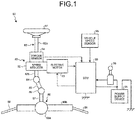
- FIG. 1 is a schematic view of a steering system in the present embodiment.
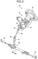
- FIG. 2 is a perspective view of the steering system in the present embodiment.
- a steering system 80 includes a steering wheel 81, a steering shaft 82, a steering-force assist mechanism 83, a universal joint 84, an intermediate shaft 85, and a universal joint 86 in the order in which force input from an operator is transmitted, and is joined to a pinion shaft 87.
- the steering system 80 includes an electronic control unit (ECU) 90, a torque sensor 94, and a vehicle speed sensor 95.
- the electric motor 93, the torque sensor 94, and the vehicle speed sensor 95 are electrically connected to the ECU 90.
- the torque sensor 94 outputs steering torque to the ECU 90 by controller area network (CAN) communication after the steering torque is transmitted to the input shaft 82a.
- the vehicle speed sensor 95 detects the traveling speed (vehicle speed) of a vehicle body that has the steering system 80 installed therein.
- the vehicle speed sensor 95 is provided in the vehicle body, and outputs the vehicle speed to the ECU 90 by CAN communication.
- FIG. 3 is a side view of the steering system in the present embodiment.
- FIG. 4 is a sectional view taken along the line A-A in FIG. 3 .
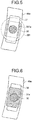
- FIG. 5 is a sectional view taken along the line B-B in FIG. 4 .
- FIG. 6 is a sectional view taken along the line C-C in FIG. 4 .
- FIG. 7 is a sectional view taken along the line D-D in FIG. 4 .
- FIG. 8 is an enlarged sectional view illustrating a part surrounding the rod in FIG. 7 .
- FIG. 9 is a perspective view of an elastic member yet to be attached to the steering system.
- FIG. 10 is a sectional view of the elastic member attached to the steering system.
- the vertical plate 61 and the vertical plate 62 are fixed to the outer circumferential surface of the outer column 51.
- the vertical plate 61 extends upward from the outer column 51 and along the lateral plate 44.
- the vertical plate 61 has a round hole 61a therethrough.
- the vertical plate 62 is a plate disposed parallel to the vertical plate 61 and faces the vertical plate 61.
- the vertical plate 62 has a round hole 62a therethrough.
- the horizontal plate 64 is a plate coupling together the vertical plate 61 and the vertical plate 62 and faces the outer circumferential surface of the outer column 51.
- the vertical plate 61, the vertical plate 62, and the horizontal plate 64 are formed integrally with one another. As illustrated in FIG. 4 , a section obtained by cutting the distance bracket 6 along a plane perpendicular to the rotation axis Z is substantially U-shaped.
- the rod 30 has a head part 301 in one end thereof and has a screw part 302 in the other end thereof.
- the rod 30 penetrates the long hole 44a, the round hole 61a, the round hole 62a, and the long hole 45a.
- the head part 301 is positioned beside the lateral plate 44, and the screw part 302 is positioned beside the lateral plate 45.
- the bearing surface of the head part 301 is placed in contact with the lateral plate 44.
- the head part 301 includes a raised part 301a. As illustrated in FIG. 4 and FIG. 5 , the raised part 301a is positioned inside the long hole 44a and faces the inner wall of the long hole 44a. When the rod 30 rotates, the raised part 301a makes contact with the inner wall of the long hole 44a.
- the raised part 301a restricts the rotation of the rod 30.
- the tilt stopper 37 makes contact with an end of the long hole 44a
- the tilt stopper 38 makes contact with an end of the long hole 45a. Impact is alleviated because the tilt stopper 37 and the tilt stopper 38 are included.
- the tilt stopper 37 and the tilt stopper 38 also function to smoothen upward and downward movements of the steering column 5.
- the elastic member 2 is attached to the rod 30, for example, from the rear side of the rod 30.
- the curled portion 23 is inserted between the rod 30 and the horizontal plate 64 from the rear side with the first arm portion 21 and the second arm portion 29 being gripped.
- the curled portion 23 is deformed by reaction force from the rod 30.
- the rod 30 is fitted to the recessed portion 25 and comes into contact with the protruding portion 27.
- the elastic member 2 is prevented from falling off the rod 30.
- positioning when the elastic member 2 is attached to the rod 30 is facilitated.
- the elastic member 2 presses the rod 30 toward the steering column 5 in the present embodiment.
- the rod 30 is pressed against the inner walls of the round hole 61a and the round hole 62a, which are illustrated in FIG. 4 . Consequently, no gap is left between the rod 30 and the inner wall of the round hole 61a and between the rod 30 and the inner wall of the round hole 62a. Consequently, rattling that occurs when the steering column 5 makes an upward or downward movement is therefore suppressed. That is, stick slip is suppressed. As s result, the steering column 5 makes smoother movements.
- the elastic member 2 does not necessarily need to be a plate spring.
- the elastic member 2 needs at least to be a member placed in contact with the rod 30 and the horizontal plate 64 and pressing the rod 30 toward the steering column 5.
- the elastic member 2 is a coil spring.
- the distance bracket 6 may be disposed on the lower side of the steering column 5. In such a case, the elastic member 2 presses the rod 30 upward.
- the rod 30 is pressed against the inner wall of the round hole 61a provided through the vertical plate 61 and the inner wall of the round hole 62a provided through the vertical plate 62. Consequently, rattling that occurs when the steering column 5 moves is suppressed. Furthermore, the elastic member 2 can be attached to the rod 30 even without a slit provided in the steering column 5.
- the steering system 80 is therefore capable of suppressing rattling that occurs when the position of the steering wheel 81 is adjusted and also capable of facilitating attachment of a member for suppressing such rattling.
- the elastic member 2 includes the recessed portion 25 salient toward the horizontal plate 64.
- the rod 30 is fitted in the recessed portion 25.
- the elastic member 2 is prevented from falling off the rod 30.
- the elastic member 2 includes the protruding portion 27 positioned nearer to the front side or the rear side than the rod 30.
- the rod 30 is placed in contact with the protruding portion 27. Thus, positioning when the elastic member 2 is attached to the rod 30 is facilitated.
- the elastic member 2 is a plate spring. Thus, manufacturing of the elastic member 2 is facilitated.
- the distance from the elastic member 2 to one of the vertical plates is equal to the distance from the elastic member 2 to the other vertical plate (the vertical plate 62).
- both of the vertical plates are less likely have gaps with the rod 30. Consequently, suppression of rattling that occurs when the position of the steering wheel 81 is adjusted is further facilitated.
Landscapes
- Engineering & Computer Science (AREA)
- Chemical & Material Sciences (AREA)
- Combustion & Propulsion (AREA)
- Transportation (AREA)
- Mechanical Engineering (AREA)
- Steering Controls (AREA)
Applications Claiming Priority (1)
| Application Number | Priority Date | Filing Date | Title |
|---|---|---|---|
| PCT/JP2017/015997 WO2018193610A1 (fr) | 2017-04-21 | 2017-04-21 | Dispositif de direction |
Publications (3)
| Publication Number | Publication Date |
|---|---|
| EP3604082A1 true EP3604082A1 (fr) | 2020-02-05 |
| EP3604082A4 EP3604082A4 (fr) | 2020-05-13 |
| EP3604082B1 EP3604082B1 (fr) | 2021-06-23 |
Family
ID=63855759
Family Applications (1)
| Application Number | Title | Priority Date | Filing Date |
|---|---|---|---|
| EP17906053.8A Active EP3604082B1 (fr) | 2017-04-21 | 2017-04-21 | Dispositif de direction |
Country Status (5)
| Country | Link |
|---|---|
| US (1) | US11097767B2 (fr) |
| EP (1) | EP3604082B1 (fr) |
| JP (1) | JP6620910B2 (fr) |
| CN (1) | CN110536825B (fr) |
| WO (1) | WO2018193610A1 (fr) |
Families Citing this family (2)
| Publication number | Priority date | Publication date | Assignee | Title |
|---|---|---|---|---|
| JP7286972B2 (ja) * | 2019-01-10 | 2023-06-06 | 日本精工株式会社 | ステアリング装置 |
| US12594982B1 (en) * | 2025-03-28 | 2026-04-07 | Steering Solutions Ip Holding Corporation | Telescope force offsetting mechanism for a steering column assembly |
Family Cites Families (16)
| Publication number | Priority date | Publication date | Assignee | Title |
|---|---|---|---|---|
| JPH09142311A (ja) * | 1995-11-24 | 1997-06-03 | Tokai Rika Co Ltd | エアバッグを備えたステアリング装置 |
| JP2000016303A (ja) | 1998-07-02 | 2000-01-18 | Toyota Motor Corp | ステアリング装置 |
| JP2003327133A (ja) * | 2002-05-13 | 2003-11-19 | Koyo Seiko Co Ltd | ステアリング装置 |
| JP5294004B2 (ja) * | 2008-08-05 | 2013-09-18 | 株式会社ジェイテクト | ステアリング装置 |
| JP2010083227A (ja) | 2008-09-30 | 2010-04-15 | Fuji Kiko Co Ltd | ステアリングコラム装置 |
| JP2010179801A (ja) * | 2009-02-06 | 2010-08-19 | Toyota Motor Corp | ステアリングコラム装置 |
| DE112010004733T5 (de) * | 2009-12-11 | 2013-04-04 | Trw Limited | Verbesserungen in Bezug auf Lenkungsbaugruppen |
| JP5662115B2 (ja) * | 2010-01-20 | 2015-01-28 | 株式会社山田製作所 | ステアリング装置 |
| JP5279743B2 (ja) * | 2010-02-19 | 2013-09-04 | 株式会社山田製作所 | ステアリング位置調整装置 |
| CN102596689B (zh) * | 2010-11-02 | 2014-03-12 | 日本精工株式会社 | 转向柱用支承装置 |
| JP2012250615A (ja) | 2011-06-02 | 2012-12-20 | Jtekt Corp | ステアリングコラムの支持装置 |
| US8770623B1 (en) * | 2013-03-14 | 2014-07-08 | Steering Solutions Ip Holding Corporation | Rake and telescope adjustable steering column with spring support |
| BR112016004438A2 (pt) * | 2014-01-30 | 2021-01-26 | Nsk Ltd. | Aparelho de orientação |
| MX2017003713A (es) * | 2014-09-22 | 2017-06-28 | Nsk Americas Inc | Modulo mejorado de absorcion de energia, para ensamble de columna de direccion de vehiculo. |
| JP6403336B2 (ja) * | 2015-04-21 | 2018-10-10 | 株式会社ジェイテクト | ステアリング装置 |
| JP2016203911A (ja) * | 2015-04-27 | 2016-12-08 | 株式会社山田製作所 | ステアリング装置 |
-
2017
- 2017-04-21 WO PCT/JP2017/015997 patent/WO2018193610A1/fr not_active Ceased
- 2017-04-21 US US16/606,267 patent/US11097767B2/en active Active
- 2017-04-21 CN CN201780089766.3A patent/CN110536825B/zh active Active
- 2017-04-21 EP EP17906053.8A patent/EP3604082B1/fr active Active
- 2017-04-21 JP JP2019513189A patent/JP6620910B2/ja active Active
Also Published As
| Publication number | Publication date |
|---|---|
| EP3604082B1 (fr) | 2021-06-23 |
| US20210129893A1 (en) | 2021-05-06 |
| WO2018193610A1 (fr) | 2018-10-25 |
| CN110536825A (zh) | 2019-12-03 |
| JP6620910B2 (ja) | 2019-12-18 |
| EP3604082A4 (fr) | 2020-05-13 |
| CN110536825B (zh) | 2022-08-09 |
| US11097767B2 (en) | 2021-08-24 |
| JPWO2018193610A1 (ja) | 2019-11-07 |
Similar Documents
| Publication | Publication Date | Title |
|---|---|---|
| EP2607202B1 (fr) | Dispositif de direction | |
| US11097767B2 (en) | Steering system | |
| JP6503882B2 (ja) | ステアリング装置 | |
| JP5892302B2 (ja) | ステアリング装置 | |
| JP2017081518A (ja) | ステアリング装置 | |
| JP6503887B2 (ja) | ステアリング装置 | |
| JP5970992B2 (ja) | 電動パワーステアリング装置 | |
| US9393987B2 (en) | Steering apparatus | |
| US11970204B2 (en) | Steering device | |
| JP6369046B2 (ja) | ステアリング装置 | |
| JP6623689B2 (ja) | ステアリング装置 | |
| JP6369045B2 (ja) | ステアリング装置 | |
| JP7575061B2 (ja) | ステアリング装置 | |
| EP2607184B1 (fr) | Dispositif de direction | |
| CN204077775U (zh) | 一种压铸镁合金转向管柱 | |
| JP5970991B2 (ja) | 電動パワーステアリング装置 | |
| JP5966700B2 (ja) | 電動パワーステアリング装置 | |
| JP2015140158A (ja) | ステアリング装置 | |
| JP2008087583A (ja) | ステアリング装置及びステアリング装置の組立方法 | |
| JP2023061298A (ja) | ステアリング装置 | |
| JP2015140173A (ja) | ステアリング装置 |
Legal Events
| Date | Code | Title | Description |
|---|---|---|---|
| STAA | Information on the status of an ep patent application or granted ep patent |
Free format text: STATUS: THE INTERNATIONAL PUBLICATION HAS BEEN MADE |
|
| PUAI | Public reference made under article 153(3) epc to a published international application that has entered the european phase |
Free format text: ORIGINAL CODE: 0009012 |
|
| STAA | Information on the status of an ep patent application or granted ep patent |
Free format text: STATUS: REQUEST FOR EXAMINATION WAS MADE |
|
| 17P | Request for examination filed |
Effective date: 20191024 |
|
| AK | Designated contracting states |
Kind code of ref document: A1 Designated state(s): AL AT BE BG CH CY CZ DE DK EE ES FI FR GB GR HR HU IE IS IT LI LT LU LV MC MK MT NL NO PL PT RO RS SE SI SK SM TR |
|
| AX | Request for extension of the european patent |
Extension state: BA ME |
|
| A4 | Supplementary search report drawn up and despatched |
Effective date: 20200414 |
|
| RIC1 | Information provided on ipc code assigned before grant |
Ipc: B62D 1/184 20060101ALI20200406BHEP Ipc: B62D 1/187 20060101ALI20200406BHEP Ipc: B62D 1/18 20060101AFI20200406BHEP |
|
| STAA | Information on the status of an ep patent application or granted ep patent |
Free format text: STATUS: EXAMINATION IS IN PROGRESS |
|
| 17Q | First examination report despatched |
Effective date: 20200610 |
|
| DAV | Request for validation of the european patent (deleted) | ||
| DAX | Request for extension of the european patent (deleted) | ||
| GRAP | Despatch of communication of intention to grant a patent |
Free format text: ORIGINAL CODE: EPIDOSNIGR1 |
|
| STAA | Information on the status of an ep patent application or granted ep patent |
Free format text: STATUS: GRANT OF PATENT IS INTENDED |
|
| INTG | Intention to grant announced |
Effective date: 20210129 |
|
| GRAS | Grant fee paid |
Free format text: ORIGINAL CODE: EPIDOSNIGR3 |
|
| GRAA | (expected) grant |
Free format text: ORIGINAL CODE: 0009210 |
|
| STAA | Information on the status of an ep patent application or granted ep patent |
Free format text: STATUS: THE PATENT HAS BEEN GRANTED |
|
| AK | Designated contracting states |
Kind code of ref document: B1 Designated state(s): AL AT BE BG CH CY CZ DE DK EE ES FI FR GB GR HR HU IE IS IT LI LT LU LV MC MK MT NL NO PL PT RO RS SE SI SK SM TR |
|
| REG | Reference to a national code |
Ref country code: GB Ref legal event code: FG4D |
|
| REG | Reference to a national code |
Ref country code: CH Ref legal event code: EP |
|
| REG | Reference to a national code |
Ref country code: DE Ref legal event code: R096 Ref document number: 602017041044 Country of ref document: DE Ref country code: AT Ref legal event code: REF Ref document number: 1404078 Country of ref document: AT Kind code of ref document: T Effective date: 20210715 |
|
| REG | Reference to a national code |
Ref country code: IE Ref legal event code: FG4D |
|
| REG | Reference to a national code |
Ref country code: LT Ref legal event code: MG9D |
|
| PG25 | Lapsed in a contracting state [announced via postgrant information from national office to epo] |
Ref country code: FI Free format text: LAPSE BECAUSE OF FAILURE TO SUBMIT A TRANSLATION OF THE DESCRIPTION OR TO PAY THE FEE WITHIN THE PRESCRIBED TIME-LIMIT Effective date: 20210623 Ref country code: LT Free format text: LAPSE BECAUSE OF FAILURE TO SUBMIT A TRANSLATION OF THE DESCRIPTION OR TO PAY THE FEE WITHIN THE PRESCRIBED TIME-LIMIT Effective date: 20210623 Ref country code: BG Free format text: LAPSE BECAUSE OF FAILURE TO SUBMIT A TRANSLATION OF THE DESCRIPTION OR TO PAY THE FEE WITHIN THE PRESCRIBED TIME-LIMIT Effective date: 20210923 Ref country code: HR Free format text: LAPSE BECAUSE OF FAILURE TO SUBMIT A TRANSLATION OF THE DESCRIPTION OR TO PAY THE FEE WITHIN THE PRESCRIBED TIME-LIMIT Effective date: 20210623 |
|
| REG | Reference to a national code |
Ref country code: AT Ref legal event code: MK05 Ref document number: 1404078 Country of ref document: AT Kind code of ref document: T Effective date: 20210623 |
|
| PG25 | Lapsed in a contracting state [announced via postgrant information from national office to epo] |
Ref country code: LV Free format text: LAPSE BECAUSE OF FAILURE TO SUBMIT A TRANSLATION OF THE DESCRIPTION OR TO PAY THE FEE WITHIN THE PRESCRIBED TIME-LIMIT Effective date: 20210623 Ref country code: NO Free format text: LAPSE BECAUSE OF FAILURE TO SUBMIT A TRANSLATION OF THE DESCRIPTION OR TO PAY THE FEE WITHIN THE PRESCRIBED TIME-LIMIT Effective date: 20210923 Ref country code: RS Free format text: LAPSE BECAUSE OF FAILURE TO SUBMIT A TRANSLATION OF THE DESCRIPTION OR TO PAY THE FEE WITHIN THE PRESCRIBED TIME-LIMIT Effective date: 20210623 Ref country code: SE Free format text: LAPSE BECAUSE OF FAILURE TO SUBMIT A TRANSLATION OF THE DESCRIPTION OR TO PAY THE FEE WITHIN THE PRESCRIBED TIME-LIMIT Effective date: 20210623 Ref country code: GR Free format text: LAPSE BECAUSE OF FAILURE TO SUBMIT A TRANSLATION OF THE DESCRIPTION OR TO PAY THE FEE WITHIN THE PRESCRIBED TIME-LIMIT Effective date: 20210924 |
|
| REG | Reference to a national code |
Ref country code: NL Ref legal event code: MP Effective date: 20210623 |
|
| PG25 | Lapsed in a contracting state [announced via postgrant information from national office to epo] |
Ref country code: EE Free format text: LAPSE BECAUSE OF FAILURE TO SUBMIT A TRANSLATION OF THE DESCRIPTION OR TO PAY THE FEE WITHIN THE PRESCRIBED TIME-LIMIT Effective date: 20210623 Ref country code: ES Free format text: LAPSE BECAUSE OF FAILURE TO SUBMIT A TRANSLATION OF THE DESCRIPTION OR TO PAY THE FEE WITHIN THE PRESCRIBED TIME-LIMIT Effective date: 20210623 Ref country code: SK Free format text: LAPSE BECAUSE OF FAILURE TO SUBMIT A TRANSLATION OF THE DESCRIPTION OR TO PAY THE FEE WITHIN THE PRESCRIBED TIME-LIMIT Effective date: 20210623 Ref country code: SM Free format text: LAPSE BECAUSE OF FAILURE TO SUBMIT A TRANSLATION OF THE DESCRIPTION OR TO PAY THE FEE WITHIN THE PRESCRIBED TIME-LIMIT Effective date: 20210623 Ref country code: RO Free format text: LAPSE BECAUSE OF FAILURE TO SUBMIT A TRANSLATION OF THE DESCRIPTION OR TO PAY THE FEE WITHIN THE PRESCRIBED TIME-LIMIT Effective date: 20210623 Ref country code: PT Free format text: LAPSE BECAUSE OF FAILURE TO SUBMIT A TRANSLATION OF THE DESCRIPTION OR TO PAY THE FEE WITHIN THE PRESCRIBED TIME-LIMIT Effective date: 20211025 Ref country code: NL Free format text: LAPSE BECAUSE OF FAILURE TO SUBMIT A TRANSLATION OF THE DESCRIPTION OR TO PAY THE FEE WITHIN THE PRESCRIBED TIME-LIMIT Effective date: 20210623 Ref country code: AT Free format text: LAPSE BECAUSE OF FAILURE TO SUBMIT A TRANSLATION OF THE DESCRIPTION OR TO PAY THE FEE WITHIN THE PRESCRIBED TIME-LIMIT Effective date: 20210623 Ref country code: CZ Free format text: LAPSE BECAUSE OF FAILURE TO SUBMIT A TRANSLATION OF THE DESCRIPTION OR TO PAY THE FEE WITHIN THE PRESCRIBED TIME-LIMIT Effective date: 20210623 |
|
| PG25 | Lapsed in a contracting state [announced via postgrant information from national office to epo] |
Ref country code: PL Free format text: LAPSE BECAUSE OF FAILURE TO SUBMIT A TRANSLATION OF THE DESCRIPTION OR TO PAY THE FEE WITHIN THE PRESCRIBED TIME-LIMIT Effective date: 20210623 |
|
| REG | Reference to a national code |
Ref country code: DE Ref legal event code: R097 Ref document number: 602017041044 Country of ref document: DE |
|
| PG25 | Lapsed in a contracting state [announced via postgrant information from national office to epo] |
Ref country code: DK Free format text: LAPSE BECAUSE OF FAILURE TO SUBMIT A TRANSLATION OF THE DESCRIPTION OR TO PAY THE FEE WITHIN THE PRESCRIBED TIME-LIMIT Effective date: 20210623 |
|
| PLBE | No opposition filed within time limit |
Free format text: ORIGINAL CODE: 0009261 |
|
| STAA | Information on the status of an ep patent application or granted ep patent |
Free format text: STATUS: NO OPPOSITION FILED WITHIN TIME LIMIT |
|
| 26N | No opposition filed |
Effective date: 20220324 |
|
| PG25 | Lapsed in a contracting state [announced via postgrant information from national office to epo] |
Ref country code: AL Free format text: LAPSE BECAUSE OF FAILURE TO SUBMIT A TRANSLATION OF THE DESCRIPTION OR TO PAY THE FEE WITHIN THE PRESCRIBED TIME-LIMIT Effective date: 20210623 |
|
| PG25 | Lapsed in a contracting state [announced via postgrant information from national office to epo] |
Ref country code: IT Free format text: LAPSE BECAUSE OF FAILURE TO SUBMIT A TRANSLATION OF THE DESCRIPTION OR TO PAY THE FEE WITHIN THE PRESCRIBED TIME-LIMIT Effective date: 20210623 |
|
| REG | Reference to a national code |
Ref country code: CH Ref legal event code: PL |
|
| GBPC | Gb: european patent ceased through non-payment of renewal fee |
Effective date: 20220421 |
|
| REG | Reference to a national code |
Ref country code: BE Ref legal event code: MM Effective date: 20220430 |
|
| PG25 | Lapsed in a contracting state [announced via postgrant information from national office to epo] |
Ref country code: MC Free format text: LAPSE BECAUSE OF FAILURE TO SUBMIT A TRANSLATION OF THE DESCRIPTION OR TO PAY THE FEE WITHIN THE PRESCRIBED TIME-LIMIT Effective date: 20210623 Ref country code: LU Free format text: LAPSE BECAUSE OF NON-PAYMENT OF DUE FEES Effective date: 20220421 Ref country code: LI Free format text: LAPSE BECAUSE OF NON-PAYMENT OF DUE FEES Effective date: 20220430 Ref country code: GB Free format text: LAPSE BECAUSE OF NON-PAYMENT OF DUE FEES Effective date: 20220421 Ref country code: FR Free format text: LAPSE BECAUSE OF NON-PAYMENT OF DUE FEES Effective date: 20220430 Ref country code: CH Free format text: LAPSE BECAUSE OF NON-PAYMENT OF DUE FEES Effective date: 20220430 |
|
| PG25 | Lapsed in a contracting state [announced via postgrant information from national office to epo] |
Ref country code: BE Free format text: LAPSE BECAUSE OF NON-PAYMENT OF DUE FEES Effective date: 20220430 |
|
| PG25 | Lapsed in a contracting state [announced via postgrant information from national office to epo] |
Ref country code: IE Free format text: LAPSE BECAUSE OF NON-PAYMENT OF DUE FEES Effective date: 20220421 |
|
| PG25 | Lapsed in a contracting state [announced via postgrant information from national office to epo] |
Ref country code: MK Free format text: LAPSE BECAUSE OF FAILURE TO SUBMIT A TRANSLATION OF THE DESCRIPTION OR TO PAY THE FEE WITHIN THE PRESCRIBED TIME-LIMIT Effective date: 20210623 Ref country code: CY Free format text: LAPSE BECAUSE OF FAILURE TO SUBMIT A TRANSLATION OF THE DESCRIPTION OR TO PAY THE FEE WITHIN THE PRESCRIBED TIME-LIMIT Effective date: 20210623 |
|
| PG25 | Lapsed in a contracting state [announced via postgrant information from national office to epo] |
Ref country code: HU Free format text: LAPSE BECAUSE OF FAILURE TO SUBMIT A TRANSLATION OF THE DESCRIPTION OR TO PAY THE FEE WITHIN THE PRESCRIBED TIME-LIMIT; INVALID AB INITIO Effective date: 20170421 |
|
| PG25 | Lapsed in a contracting state [announced via postgrant information from national office to epo] |
Ref country code: MT Free format text: LAPSE BECAUSE OF FAILURE TO SUBMIT A TRANSLATION OF THE DESCRIPTION OR TO PAY THE FEE WITHIN THE PRESCRIBED TIME-LIMIT Effective date: 20210623 |
|
| PGFP | Annual fee paid to national office [announced via postgrant information from national office to epo] |
Ref country code: DE Payment date: 20250305 Year of fee payment: 9 |
|
| PG25 | Lapsed in a contracting state [announced via postgrant information from national office to epo] |
Ref country code: TR Free format text: LAPSE BECAUSE OF FAILURE TO SUBMIT A TRANSLATION OF THE DESCRIPTION OR TO PAY THE FEE WITHIN THE PRESCRIBED TIME-LIMIT Effective date: 20210623 |