EP3604722A1 - Serrure - Google Patents
Serrure Download PDFInfo
- Publication number
- EP3604722A1 EP3604722A1 EP19187896.6A EP19187896A EP3604722A1 EP 3604722 A1 EP3604722 A1 EP 3604722A1 EP 19187896 A EP19187896 A EP 19187896A EP 3604722 A1 EP3604722 A1 EP 3604722A1
- Authority
- EP
- European Patent Office
- Prior art keywords
- rotary latch
- pawl
- leg
- counter bearing
- engagement
- Prior art date
- Legal status (The legal status is an assumption and is not a legal conclusion. Google has not performed a legal analysis and makes no representation as to the accuracy of the status listed.)
- Granted
Links
Images

Classifications
-
- E—FIXED CONSTRUCTIONS
- E05—LOCKS; KEYS; WINDOW OR DOOR FITTINGS; SAFES
- E05B—LOCKS; ACCESSORIES THEREFOR; HANDCUFFS
- E05B83/00—Vehicle locks specially adapted for particular types of wing or vehicle
- E05B83/16—Locks for luggage compartments, car boot lids or car bonnets
-
- E—FIXED CONSTRUCTIONS
- E05—LOCKS; KEYS; WINDOW OR DOOR FITTINGS; SAFES
- E05B—LOCKS; ACCESSORIES THEREFOR; HANDCUFFS
- E05B83/00—Vehicle locks specially adapted for particular types of wing or vehicle
- E05B83/16—Locks for luggage compartments, car boot lids or car bonnets
- E05B83/18—Locks for luggage compartments, car boot lids or car bonnets for car boot lids or rear luggage compartments
-
- B—PERFORMING OPERATIONS; TRANSPORTING
- B62—LAND VEHICLES FOR TRAVELLING OTHERWISE THAN ON RAILS
- B62D—MOTOR VEHICLES; TRAILERS
- B62D25/00—Superstructure or monocoque structure sub-units; Parts or details thereof not otherwise provided for
- B62D25/08—Front or rear portions
- B62D25/10—Bonnets or lids, e.g. for trucks, tractors, busses, work vehicles
- B62D25/12—Parts or details thereof
-
- E—FIXED CONSTRUCTIONS
- E05—LOCKS; KEYS; WINDOW OR DOOR FITTINGS; SAFES
- E05B—LOCKS; ACCESSORIES THEREFOR; HANDCUFFS
- E05B81/00—Power-actuated vehicle locks
- E05B81/02—Power-actuated vehicle locks characterised by the type of actuators used
- E05B81/04—Electrical
- E05B81/06—Electrical using rotary motors
-
- E—FIXED CONSTRUCTIONS
- E05—LOCKS; KEYS; WINDOW OR DOOR FITTINGS; SAFES
- E05B—LOCKS; ACCESSORIES THEREFOR; HANDCUFFS
- E05B81/00—Power-actuated vehicle locks
- E05B81/12—Power-actuated vehicle locks characterised by the function or purpose of the powered actuators
- E05B81/14—Power-actuated vehicle locks characterised by the function or purpose of the powered actuators operating on bolt detents, e.g. for unlatching the bolt
- E05B81/15—Power-actuated vehicle locks characterised by the function or purpose of the powered actuators operating on bolt detents, e.g. for unlatching the bolt with means preventing the detent to return to its latching position before the bolt has moved to the unlatched position
-
- E—FIXED CONSTRUCTIONS
- E05—LOCKS; KEYS; WINDOW OR DOOR FITTINGS; SAFES
- E05B—LOCKS; ACCESSORIES THEREFOR; HANDCUFFS
- E05B85/00—Details of vehicle locks not provided for in groups E05B77/00 - E05B83/00
-
- E—FIXED CONSTRUCTIONS
- E05—LOCKS; KEYS; WINDOW OR DOOR FITTINGS; SAFES
- E05B—LOCKS; ACCESSORIES THEREFOR; HANDCUFFS
- E05B85/00—Details of vehicle locks not provided for in groups E05B77/00 - E05B83/00
- E05B85/20—Bolts or detents
- E05B85/24—Bolts rotating about an axis
- E05B85/26—Cooperation between bolts and detents
Definitions
- the present invention relates to a lock, in particular for a tailgate of a motor vehicle, with a rotary latch which can be rotated about an axis of rotation between an open position and a closed position, a pawl which is in engagement with the rotary latch in its closed position and can be detached therefrom to release the rotary latch , and a leg spring, against the restoring force of which the rotary latch can be rotated from its open position into its closed position.
- Such a lock is known in principle and is used to lock a closed locking device, such as a tailgate, a bonnet or a door.
- the lock receives a striker which is engaged by the rotary latch in its closed position.
- the rotary latch engages with a pawl, which blocks the rotary latch against unscrewing from the closed position into an open position releasing the striker.
- the pawl is acted upon by a spring force of a pawl spring which presses the pawl against the catch.
- the leg spring acting on the catch causes the catch to open from the closed position to its open position and the striker to be released from the catch.
- the unlocked locking device can be opened.
- the locking device is loaded in an unusual way, for example due to snow remaining on the locking device after heavy snowfall.
- the spring force of the leg spring is not sufficient to turn the catch into its open position, since the locking bracket received in the catch prevents the catch from being opened due to the snow load.
- the pawl normally closes again after a predetermined period of time, it would block the catch again, i.e. the locking device would then no longer be able to be opened even if it were freed of its load, such as snow. Rather, the unlocking process of the lock would then have to be carried out again completely, which in practice is perceived as uncomfortable.
- An object of the invention is to provide a lock of the aforementioned type with a simpler construction, in particular with fewer components.
- the lock according to the invention comprises a rotary latch which can be rotated about an axis of rotation between an open position and a closed position, a pawl which engages with the rotary latch in its closed position and can be released from it to release the rotary latch, and a leg spring, against the restoring force of which the rotary latch is released its open position can be rotated into its closed position.
- the lock according to the invention is characterized in that that a first leg of the leg spring forms a support section which, by releasing the pawl from the catch, can be brought into engagement with a counter-bearing formed on the pawl or on an adjusting lever cooperating with the pawl, in order to hold the pawl in a raised position, the Engagement between the support section and the counter bearing by a rotation of the rotary latch from the closed position to the open position is releasable.
- the invention is based on the general idea of providing the leg spring which is already present in a lock for turning the catch from the closed position into the open position with an additional function, in that a first leg of the leg spring forms a support section which, by disengaging the pawl and catch, also can be brought into engagement with a counter-bearing formed on the pawl or on an adjusting lever cooperating with the pawl, in order to hold the pawl in its raised position until the catch is turned up to its open position. This prevents the pawl from closing prematurely and blocking the catch in its closed position or in an intermediate position before it has reached its open position.
- leg spring serves both to open the rotary latch and to hold the raised pawl, in particular over a certain angle of rotation of the rotary latch, the leg spring performs a double function. This has the advantage that fewer components are required, as a result of which the lock has a simpler construction, is more reliable and, moreover, manufacturing costs of the lock can be reduced.
- the lock according to the invention can be used not only for a tailgate, but also for a bonnet, a door or the like.
- the pawl can be pivoted about a pivot axis oriented at least approximately parallel to the axis of rotation. If the lock has an actuating lever which interacts with the pawl, the actuating lever and the pawl can be pivotable about a common pivot axis.
- the adjusting lever preferably has a driver for the pawl, which serves to lift the pawl when the adjusting lever is pivoted away from the rotary latch.
- the control lever and the pawl always move away from the catch.
- independent pivoting of the pawl and adjusting lever possible.
- the driver of the actuating lever preferably also prevents the pawl from falling back into its position blocking the catch, as long as the actuating lever is in its position pivoted away from the catch.
- a means for releasing the engagement between the support section and the counter bearing is provided from an advanced rotation of the catch from the closed position to the open position.
- An advanced rotation of the rotary latch is to be understood to mean that the rotary latch is rotated at least so far in the direction of the open position that the pawl falling from the raised position does not come into engagement with either a main catch or with a possibly provided forward catch of the rotary latch.
- the rotary latch is rotated by at least half, preferably by at least three quarters and particularly preferably by at least four fifths of the distance between the closed position and the open position in the event of an advanced rotation.
- the engagement between the support section and the counter bearing is released when the rotary latch is in its open position.
- a ramp is preferably provided, on which the support section runs when the rotary latch is rotated from the closed position into its open position.
- the ramp is preferably formed on the rotary latch, which makes the lock even easier to design.
- the counter bearing and the support section engaged with the counter bearing preferably lie in a common plane.
- the common plane can be aligned at least approximately perpendicular to the axis of rotation of the catch.
- the common plane is preferably parallel to a plane in which the rotary latch can be rotated.
- the support section can protrude from the common plane.
- the support section is deflected away from the rotary latch in the axial direction, ie in the direction of the axis of rotation of the rotary latch.
- the first leg of the leg spring can be designed to be resilient, as a result of which the first leg can be deflected particularly well and, when the catch is rotated from the open position to the closed position, returns to its original position, ie when the first leg is not on the Ramp rests.
- the pawl or the actuating lever can have a guide section for the first leg of the leg spring protruding from the common plane, which, when the Pawl of the rotary latch or leads the first leg away from the rotary latch when the adjusting lever pivots.
- the guide section is preferably oriented transversely, in particular at least approximately perpendicularly, to the counter bearing.
- the guide section describes an arc, which at least in sections at least approximately coaxially surrounds the pivot axis of the pawl.
- the ramp can furthermore have a support projection designed to support the pawl or the actuating lever if, when the pawl is released or the actuating lever is pivoted away from the catch, the engagement between the support section of the leg spring and the counter bearing of the pawl or of the control lever is released.
- the support projection which is supported on the support surface prevents the support section and the counterbearing from engaging again when the rotary latch is rotated from the open position to the closed position.
- the support surface preferably faces the pawl or the actuating lever.
- the support projection is preferably formed in the direction between the axis of rotation of the rotary latch in a plane between the counter bearing and a mouth of the rotary latch. It can also protrude further in the direction of the catch than the counter bearing.
- the mouth of the rotary latch serves to receive the striker in the closed position of the rotary latch.
- the ramp describes an arc at least in sections.
- the circular arc-like ramp can be the axis of rotation of the catch at least in sections and at least approximately coaxially. Due to the circular arc-like configuration of the ramp, the support surface formed on the ramp is preferably curved accordingly, as a result of which the support projection formed on the pawl can slide better along the support surface when the catch is rotated.
- the support section can be produced in a particularly simple manner by bending, in particular bending through an angle of at least approximately 90 °, an end section of the first leg of the leg spring, so that the support section forms an end section of the first leg of the leg spring. It goes without saying that the support section can also be formed on another section, for example the support section can also be formed on an intermediate section of the first leg offset from the end section.
- the first leg of the leg spring is preferably secured against rotation when the catch is rotated, i.e. the first leg does not move when the catch is rotated.
- the first leg of the leg spring is advantageously supported on a housing provided for mounting the catch.
- a second leg of the leg spring can be supported on the rotary latch and can also move when the rotary latch is rotated.
- the leg spring preferably consists of a metal material, in particular a spring steel. This makes the leg spring particularly stable. In addition, such a choice of material enables the first leg of the leg spring to be resilient. Basically, the leg spring can also consist of another material, such as a plastic material. According to an advantageous embodiment, an electric motor is provided for lifting the pawl.
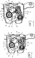
- the figures show a lock, in particular for a tailgate or bonnet of a motor vehicle.
- the lock includes a between an open position ( 3 and 4 ) and a closed position ( 1 and 2 )
- Rotatable latch 10 rotatable about an axis of rotation A and a pawl 12 pivotable about a pivot axis B.
- the axis of rotation A of the rotary latch 10 and the pivot axis B of the pawl 12 are spaced apart and at least approximately parallel to one another.
- the rotary latch 10 has a mouth 14 which, in the closed position of the rotary latch 10, serves to engage behind a striker (not shown in the figures) in order to lock the tailgate or the bonnet.
- a striker not shown in the figures
- a torsion spring 16 acting on the rotary latch 10 with a spring force causes the rotary latch 10 to rotate independently from the closed position into the open position, ie the rotary latch 10 can be rotated from the open position into the closed position against the restoring force of the leg spring 16.
- the pawl 12 acts in a closed position with one in the 2 to 4 Main catch 17 of the catch 10, which can be seen particularly well, and blocks the catch 10 in the closed position against being turned open. By lifting the pawl 12, ie by lifting the blocking, the rotary latch 10 is released so that it can turn open.
- a drive means is provided in the form of an electric motor.
- the drive means serves a in 1 and 2 To drive worm gear 18, not shown, by means of which an adjusting lever 19 cooperating with the pawl 12 can be moved or lifted out of the catch 10 from its initial position.
- the actuating lever 19 has a driver which cannot be seen in the figures and which, when the actuating lever 19 is pivoted away from the rotary latch 10, pawls the pawl 12 and releases it from the rotary latch 10, thereby releasing the rotary latch 10 so that the rotary latch 10 is in its position Open position can turn.
- the actuating lever 19 and the pawl 12 perform a joint pivoting about the pivot axis B. In the opposite direction, ie towards the rotary latch, an independent pivoting of the pawl 12 and adjusting lever 19 is possible, so that the pawl 12 into the rotary latch 10 blocking position and the adjusting lever 19 can pivot back into its starting position.
- the driver formed on the adjusting lever 19 not only serves to lift the pawl 12, but also prevents the raised pawl from falling back into the position blocking the catch 10 as long as the adjusting lever 19 is in its position pivoted away from the catch.
- the leg spring 16 consists of a metal material and has a turn 20 coaxially surrounding the axis of rotation A of the catch 10.
- the leg spring 16 is preferably made of a spring steel.
- a first leg 22 and a second leg 24 emerge from the turn 20 of the leg spring 16.
- the first leg 22 is secured against rotation together with the rotary latch 10 by a housing provided for mounting the rotary latch 10.
- the second leg 24, on the other hand, is supported on the rotary latch 10 and moves with it when the rotary latch 10 is rotated.
- a support section 26 is formed on an end section of the first leg 22, which can be brought into engagement by lifting the pawl 12 with a counter bearing 28 formed on the actuating lever 19 in order to hold the pawl 12 in a raised position ( 2 to 4 ).
- the counter bearing 28 can in principle also be formed on the pawl 12 if no actuating lever 19 is provided for lifting the pawl 12.
- the counter bearing 28 formed on the pawl 12 fulfills the same function as the counter bearing 28 formed on the actuating lever 19.
- the engagement between the support section 26 of the leg spring 16 and the counterbearing 28 of the actuating lever 19 can occur when the rotary latch 10 is advanced from the closed position release into the open position.
- a ramp 30 is formed on the rotary latch 10, which describes an arc at least in sections. In order to release the engagement between the support section 26 and the counter bearing 28, the first leg 22 runs onto the ramp 30 when the rotary latch 10 is rotated from the closed position into the open position.
- the support section 26 and the counter bearing 28 are in engagement, they lie in a common plane. If the first leg 22 runs when the rotary latch 10 is rotated from the closed position into the open position on the ramp 30, the first leg 22 is deflected in the axial direction with respect to the axis of rotation A of the rotary latch 10 in the direction away from the rotary latch 10, so to speak raised until the support section 26 protrudes from the common plane and the engagement between the support section 26 and the counter bearing 28 is released.
- the ramp 30 also has a support surface 32 facing the adjusting lever 19, on which a support projection 34 formed on the pawl 12 is supported when the engagement between the support section 26 formed on the first leg 22 of the leg spring 16 and the counter bearing 28 is released.
- the support projection 34 protrudes further in the direction of the axis of rotation A of the rotary latch 10 than the counter bearing 28.
- the support projection 34 lies in the direction of the axis of rotation A of the rotary latch 10 in a plane which is between the counter bearing 28 and the Mouth 14 of the catch 10 is formed. If no adjusting lever 19 is provided for lifting the pawl 12, the support projection 34 can also be on the pawl 12 may be formed, wherein the support projection 34 formed on the pawl 12 fulfills the same function as the support projection 34 formed on the actuating lever 19.
- Fig. 1 illustrated closed position of the rotary latch 10 explained.
- the drive means moves the worm gear 18 by means of an opening signal, as a result of which the actuating lever 19 or the pawl 12 is raised and moved away from the rotary latch 10.
- the first leg 22 is guided by a guide section 36 formed on the actuating lever 19.
- the guide section 36 is preferably oriented transversely or at least approximately perpendicular to the counter bearing 28.
- the guide section 36 can also be formed on the pawl 12 if no actuating lever 19 is provided.
- the catch 10 By rotating the catch 10 from the closed position into the open position, the first leg 22 runs onto the ramp 30 and the engagement between the support section 26 of the first leg 22 and the counter bearing 28 is released. At the same time, the support projection 34 strikes the support surface 32 of the ramp 30, as a result of which the pawl 12 is still held in the raised position even when the rotary latch 10 is in the open position.
- the ramp 30 prevents the support section 26 and the counter bearing 28 from being able to engage before the rotary latch 10 reaches its closed position.
- the pawl 12 and the actuating lever 19 can pivot back freely, and the catch 10 is blocked again by the cooperation of the catch 12 with the main catch 17 against unscrewing into the open position.
Landscapes
- Engineering & Computer Science (AREA)
- Chemical & Material Sciences (AREA)
- Combustion & Propulsion (AREA)
- Transportation (AREA)
- Mechanical Engineering (AREA)
- Lock And Its Accessories (AREA)
Applications Claiming Priority (1)
| Application Number | Priority Date | Filing Date | Title |
|---|---|---|---|
| DE102018118712.2A DE102018118712A1 (de) | 2018-08-01 | 2018-08-01 | Schloss |
Publications (2)
| Publication Number | Publication Date |
|---|---|
| EP3604722A1 true EP3604722A1 (fr) | 2020-02-05 |
| EP3604722B1 EP3604722B1 (fr) | 2021-01-06 |
Family
ID=67438581
Family Applications (1)
| Application Number | Title | Priority Date | Filing Date |
|---|---|---|---|
| EP19187896.6A Active EP3604722B1 (fr) | 2018-08-01 | 2019-07-23 | Serrure |
Country Status (3)
| Country | Link |
|---|---|
| EP (1) | EP3604722B1 (fr) |
| CN (1) | CN110792340B (fr) |
| DE (1) | DE102018118712A1 (fr) |
Citations (3)
| Publication number | Priority date | Publication date | Assignee | Title |
|---|---|---|---|---|
| DE19932291A1 (de) * | 1999-01-22 | 2000-07-27 | Witte Velbert Gmbh & Co Kg | Verschluß mit Drehfalle und Sperrklinke |
| EP1617023A2 (fr) * | 2004-07-13 | 2006-01-18 | Huf Hülsbeck & Fürst GmbH & Co. KG | Dispositif d'actionnement des serrures pour portes ou ouvrants d'un véhicule |
| WO2015062578A2 (fr) * | 2013-11-02 | 2015-05-07 | Kiekert Ag | Serrure dotée d'un levier à mémoire pour un véhicule à moteur |
Family Cites Families (6)
| Publication number | Priority date | Publication date | Assignee | Title |
|---|---|---|---|---|
| DE102011114148A1 (de) * | 2011-09-23 | 2013-03-28 | BÖCO Böddecker & Co. GmbH & Co. KG | Schließvorrichtung für ein Kraftfahrzeug |
| CN203835080U (zh) * | 2014-04-22 | 2014-09-17 | 伟速达(中国)汽车安全系统有限公司 | 一种采用两级棘爪机构的新型汽车尾门锁 |
| CN204552361U (zh) * | 2015-01-28 | 2015-08-12 | 上海通用汽车有限公司 | 一种用于安装在汽车尾门上的锁具 |
| CN206625691U (zh) * | 2017-02-23 | 2017-11-10 | 梁永军 | 一种汽车尾门电吸锁机构 |
| CN207110745U (zh) * | 2017-08-08 | 2018-03-16 | 北京车和家信息技术有限公司 | 尾门锁、背门总成及车辆 |
| CN107675968B (zh) * | 2017-10-31 | 2022-09-20 | 无锡瑞林智能科技有限公司 | 自吸尾门锁传动机构 |
-
2018
- 2018-08-01 DE DE102018118712.2A patent/DE102018118712A1/de not_active Withdrawn
-
2019
- 2019-07-23 EP EP19187896.6A patent/EP3604722B1/fr active Active
- 2019-07-25 CN CN201910676918.0A patent/CN110792340B/zh active Active
Patent Citations (3)
| Publication number | Priority date | Publication date | Assignee | Title |
|---|---|---|---|---|
| DE19932291A1 (de) * | 1999-01-22 | 2000-07-27 | Witte Velbert Gmbh & Co Kg | Verschluß mit Drehfalle und Sperrklinke |
| EP1617023A2 (fr) * | 2004-07-13 | 2006-01-18 | Huf Hülsbeck & Fürst GmbH & Co. KG | Dispositif d'actionnement des serrures pour portes ou ouvrants d'un véhicule |
| WO2015062578A2 (fr) * | 2013-11-02 | 2015-05-07 | Kiekert Ag | Serrure dotée d'un levier à mémoire pour un véhicule à moteur |
Also Published As
| Publication number | Publication date |
|---|---|
| CN110792340A (zh) | 2020-02-14 |
| CN110792340B (zh) | 2021-12-07 |
| DE102018118712A1 (de) | 2020-02-06 |
| EP3604722B1 (fr) | 2021-01-06 |
Similar Documents
| Publication | Publication Date | Title |
|---|---|---|
| EP2326781B1 (fr) | Unité de serrure comportant des cliquets d'arrêt à plusieurs parties et un cliquet de blocage précontraint par ressort | |
| EP2893108B1 (fr) | Serrure de porte de véhicule automobile | |
| EP2633140B1 (fr) | Serrure de porte de véhicule automobile | |
| EP2823120B1 (fr) | Serrure pour hayon ou porte | |
| DE102012025403A1 (de) | Kraftfahrzeugtürverschluss | |
| EP2929112B1 (fr) | Serrure pour un coffre ou une porte | |
| DE102009029023A1 (de) | Kraftfahrzeugschloss | |
| EP2925945B1 (fr) | Serrure de véhicule automobile | |
| WO2010142261A1 (fr) | Serrure à système de guidage forcé pour cliquet | |
| DE102009029031A1 (de) | Gesperre | |
| DE102008061524A1 (de) | Mehrklinken-Gesperre mit Rasthaken | |
| EP3784855B1 (fr) | Serrure de véhicule automobile | |
| DE102013207725A1 (de) | Kraftfahrzeugschloss | |
| EP2844812B1 (fr) | Serrure pour une trappe ou une porte | |
| DE102009050077A1 (de) | Fahrzeugschloss | |
| EP2929113B1 (fr) | Serrure pour une coffre ou une porte | |
| DE102004032147A1 (de) | Schloss eines bewegbaren Elements einer Fahrzeugkarosserie | |
| EP1669526B1 (fr) | Serrure de véhicule automobile | |
| DE102018128420A1 (de) | Kraftfahrzeugschloss | |
| EP3604722B1 (fr) | Serrure | |
| EP3615752B1 (fr) | Serrure de portière de véhicule automobile | |
| EP2670934B1 (fr) | Serrure de véhicule à moteur | |
| DE102017002045B4 (de) | Fahrzeugschloss | |
| DE102009026452B4 (de) | Auslösehebel mit einer ein öffnendes Moment für die Drehfalle erzeugenden Kontur bei Mehrklinken-Gesperre | |
| DE4339654C2 (de) | Kraftfahrzeugtürverschluß |
Legal Events
| Date | Code | Title | Description |
|---|---|---|---|
| PUAI | Public reference made under article 153(3) epc to a published international application that has entered the european phase |
Free format text: ORIGINAL CODE: 0009012 |
|
| STAA | Information on the status of an ep patent application or granted ep patent |
Free format text: STATUS: THE APPLICATION HAS BEEN PUBLISHED |
|
| AK | Designated contracting states |
Kind code of ref document: A1 Designated state(s): AL AT BE BG CH CY CZ DE DK EE ES FI FR GB GR HR HU IE IS IT LI LT LU LV MC MK MT NL NO PL PT RO RS SE SI SK SM TR |
|
| AX | Request for extension of the european patent |
Extension state: BA ME |
|
| STAA | Information on the status of an ep patent application or granted ep patent |
Free format text: STATUS: REQUEST FOR EXAMINATION WAS MADE |
|
| 17P | Request for examination filed |
Effective date: 20200703 |
|
| RBV | Designated contracting states (corrected) |
Designated state(s): AL AT BE BG CH CY CZ DE DK EE ES FI FR GB GR HR HU IE IS IT LI LT LU LV MC MK MT NL NO PL PT RO RS SE SI SK SM TR |
|
| RIC1 | Information provided on ipc code assigned before grant |
Ipc: E05B 81/14 20140101AFI20200723BHEP Ipc: E05B 83/16 20140101ALI20200723BHEP Ipc: E05B 85/26 20140101ALI20200723BHEP |
|
| GRAP | Despatch of communication of intention to grant a patent |
Free format text: ORIGINAL CODE: EPIDOSNIGR1 |
|
| STAA | Information on the status of an ep patent application or granted ep patent |
Free format text: STATUS: GRANT OF PATENT IS INTENDED |
|
| INTG | Intention to grant announced |
Effective date: 20200828 |
|
| GRAS | Grant fee paid |
Free format text: ORIGINAL CODE: EPIDOSNIGR3 |
|
| GRAA | (expected) grant |
Free format text: ORIGINAL CODE: 0009210 |
|
| STAA | Information on the status of an ep patent application or granted ep patent |
Free format text: STATUS: THE PATENT HAS BEEN GRANTED |
|
| AK | Designated contracting states |
Kind code of ref document: B1 Designated state(s): AL AT BE BG CH CY CZ DE DK EE ES FI FR GB GR HR HU IE IS IT LI LT LU LV MC MK MT NL NO PL PT RO RS SE SI SK SM TR |
|
| REG | Reference to a national code |
Ref country code: GB Ref legal event code: FG4D Free format text: NOT ENGLISH |
|
| REG | Reference to a national code |
Ref country code: AT Ref legal event code: REF Ref document number: 1352547 Country of ref document: AT Kind code of ref document: T Effective date: 20210115 Ref country code: CH Ref legal event code: EP |
|
| REG | Reference to a national code |
Ref country code: DE Ref legal event code: R096 Ref document number: 502019000642 Country of ref document: DE |
|
| REG | Reference to a national code |
Ref country code: IE Ref legal event code: FG4D Free format text: LANGUAGE OF EP DOCUMENT: GERMAN |
|
| REG | Reference to a national code |
Ref country code: NL Ref legal event code: MP Effective date: 20210106 |
|
| REG | Reference to a national code |
Ref country code: LT Ref legal event code: MG9D |
|
| PG25 | Lapsed in a contracting state [announced via postgrant information from national office to epo] |
Ref country code: LT Free format text: LAPSE BECAUSE OF FAILURE TO SUBMIT A TRANSLATION OF THE DESCRIPTION OR TO PAY THE FEE WITHIN THE PRESCRIBED TIME-LIMIT Effective date: 20210106 Ref country code: NO Free format text: LAPSE BECAUSE OF FAILURE TO SUBMIT A TRANSLATION OF THE DESCRIPTION OR TO PAY THE FEE WITHIN THE PRESCRIBED TIME-LIMIT Effective date: 20210406 Ref country code: PT Free format text: LAPSE BECAUSE OF FAILURE TO SUBMIT A TRANSLATION OF THE DESCRIPTION OR TO PAY THE FEE WITHIN THE PRESCRIBED TIME-LIMIT Effective date: 20210506 Ref country code: FI Free format text: LAPSE BECAUSE OF FAILURE TO SUBMIT A TRANSLATION OF THE DESCRIPTION OR TO PAY THE FEE WITHIN THE PRESCRIBED TIME-LIMIT Effective date: 20210106 Ref country code: GR Free format text: LAPSE BECAUSE OF FAILURE TO SUBMIT A TRANSLATION OF THE DESCRIPTION OR TO PAY THE FEE WITHIN THE PRESCRIBED TIME-LIMIT Effective date: 20210407 Ref country code: BG Free format text: LAPSE BECAUSE OF FAILURE TO SUBMIT A TRANSLATION OF THE DESCRIPTION OR TO PAY THE FEE WITHIN THE PRESCRIBED TIME-LIMIT Effective date: 20210406 Ref country code: HR Free format text: LAPSE BECAUSE OF FAILURE TO SUBMIT A TRANSLATION OF THE DESCRIPTION OR TO PAY THE FEE WITHIN THE PRESCRIBED TIME-LIMIT Effective date: 20210106 |
|
| PG25 | Lapsed in a contracting state [announced via postgrant information from national office to epo] |
Ref country code: RS Free format text: LAPSE BECAUSE OF FAILURE TO SUBMIT A TRANSLATION OF THE DESCRIPTION OR TO PAY THE FEE WITHIN THE PRESCRIBED TIME-LIMIT Effective date: 20210106 Ref country code: SE Free format text: LAPSE BECAUSE OF FAILURE TO SUBMIT A TRANSLATION OF THE DESCRIPTION OR TO PAY THE FEE WITHIN THE PRESCRIBED TIME-LIMIT Effective date: 20210106 Ref country code: LV Free format text: LAPSE BECAUSE OF FAILURE TO SUBMIT A TRANSLATION OF THE DESCRIPTION OR TO PAY THE FEE WITHIN THE PRESCRIBED TIME-LIMIT Effective date: 20210106 Ref country code: PL Free format text: LAPSE BECAUSE OF FAILURE TO SUBMIT A TRANSLATION OF THE DESCRIPTION OR TO PAY THE FEE WITHIN THE PRESCRIBED TIME-LIMIT Effective date: 20210106 |
|
| PG25 | Lapsed in a contracting state [announced via postgrant information from national office to epo] |
Ref country code: IS Free format text: LAPSE BECAUSE OF FAILURE TO SUBMIT A TRANSLATION OF THE DESCRIPTION OR TO PAY THE FEE WITHIN THE PRESCRIBED TIME-LIMIT Effective date: 20210506 |
|
| REG | Reference to a national code |
Ref country code: DE Ref legal event code: R097 Ref document number: 502019000642 Country of ref document: DE |
|
| PG25 | Lapsed in a contracting state [announced via postgrant information from national office to epo] |
Ref country code: SM Free format text: LAPSE BECAUSE OF FAILURE TO SUBMIT A TRANSLATION OF THE DESCRIPTION OR TO PAY THE FEE WITHIN THE PRESCRIBED TIME-LIMIT Effective date: 20210106 Ref country code: EE Free format text: LAPSE BECAUSE OF FAILURE TO SUBMIT A TRANSLATION OF THE DESCRIPTION OR TO PAY THE FEE WITHIN THE PRESCRIBED TIME-LIMIT Effective date: 20210106 Ref country code: CZ Free format text: LAPSE BECAUSE OF FAILURE TO SUBMIT A TRANSLATION OF THE DESCRIPTION OR TO PAY THE FEE WITHIN THE PRESCRIBED TIME-LIMIT Effective date: 20210106 |
|
| PLBE | No opposition filed within time limit |
Free format text: ORIGINAL CODE: 0009261 |
|
| STAA | Information on the status of an ep patent application or granted ep patent |
Free format text: STATUS: NO OPPOSITION FILED WITHIN TIME LIMIT |
|
| PG25 | Lapsed in a contracting state [announced via postgrant information from national office to epo] |
Ref country code: DK Free format text: LAPSE BECAUSE OF FAILURE TO SUBMIT A TRANSLATION OF THE DESCRIPTION OR TO PAY THE FEE WITHIN THE PRESCRIBED TIME-LIMIT Effective date: 20210106 Ref country code: SK Free format text: LAPSE BECAUSE OF FAILURE TO SUBMIT A TRANSLATION OF THE DESCRIPTION OR TO PAY THE FEE WITHIN THE PRESCRIBED TIME-LIMIT Effective date: 20210106 Ref country code: RO Free format text: LAPSE BECAUSE OF FAILURE TO SUBMIT A TRANSLATION OF THE DESCRIPTION OR TO PAY THE FEE WITHIN THE PRESCRIBED TIME-LIMIT Effective date: 20210106 |
|
| 26N | No opposition filed |
Effective date: 20211007 |
|
| PG25 | Lapsed in a contracting state [announced via postgrant information from national office to epo] |
Ref country code: ES Free format text: LAPSE BECAUSE OF FAILURE TO SUBMIT A TRANSLATION OF THE DESCRIPTION OR TO PAY THE FEE WITHIN THE PRESCRIBED TIME-LIMIT Effective date: 20210106 Ref country code: AL Free format text: LAPSE BECAUSE OF FAILURE TO SUBMIT A TRANSLATION OF THE DESCRIPTION OR TO PAY THE FEE WITHIN THE PRESCRIBED TIME-LIMIT Effective date: 20210106 |
|
| PG25 | Lapsed in a contracting state [announced via postgrant information from national office to epo] |
Ref country code: SI Free format text: LAPSE BECAUSE OF FAILURE TO SUBMIT A TRANSLATION OF THE DESCRIPTION OR TO PAY THE FEE WITHIN THE PRESCRIBED TIME-LIMIT Effective date: 20210106 |
|
| PG25 | Lapsed in a contracting state [announced via postgrant information from national office to epo] |
Ref country code: MC Free format text: LAPSE BECAUSE OF FAILURE TO SUBMIT A TRANSLATION OF THE DESCRIPTION OR TO PAY THE FEE WITHIN THE PRESCRIBED TIME-LIMIT Effective date: 20210106 |
|
| REG | Reference to a national code |
Ref country code: BE Ref legal event code: MM Effective date: 20210731 |
|
| PG25 | Lapsed in a contracting state [announced via postgrant information from national office to epo] |
Ref country code: IT Free format text: LAPSE BECAUSE OF FAILURE TO SUBMIT A TRANSLATION OF THE DESCRIPTION OR TO PAY THE FEE WITHIN THE PRESCRIBED TIME-LIMIT Effective date: 20210106 |
|
| PG25 | Lapsed in a contracting state [announced via postgrant information from national office to epo] |
Ref country code: IS Free format text: LAPSE BECAUSE OF FAILURE TO SUBMIT A TRANSLATION OF THE DESCRIPTION OR TO PAY THE FEE WITHIN THE PRESCRIBED TIME-LIMIT Effective date: 20210506 Ref country code: LU Free format text: LAPSE BECAUSE OF NON-PAYMENT OF DUE FEES Effective date: 20210723 |
|
| PG25 | Lapsed in a contracting state [announced via postgrant information from national office to epo] |
Ref country code: IE Free format text: LAPSE BECAUSE OF NON-PAYMENT OF DUE FEES Effective date: 20210723 Ref country code: BE Free format text: LAPSE BECAUSE OF NON-PAYMENT OF DUE FEES Effective date: 20210731 |
|
| REG | Reference to a national code |
Ref country code: CH Ref legal event code: PL |
|
| PG25 | Lapsed in a contracting state [announced via postgrant information from national office to epo] |
Ref country code: LI Free format text: LAPSE BECAUSE OF NON-PAYMENT OF DUE FEES Effective date: 20220731 Ref country code: CH Free format text: LAPSE BECAUSE OF NON-PAYMENT OF DUE FEES Effective date: 20220731 |
|
| PG25 | Lapsed in a contracting state [announced via postgrant information from national office to epo] |
Ref country code: NL Free format text: LAPSE BECAUSE OF NON-PAYMENT OF DUE FEES Effective date: 20210206 Ref country code: CY Free format text: LAPSE BECAUSE OF FAILURE TO SUBMIT A TRANSLATION OF THE DESCRIPTION OR TO PAY THE FEE WITHIN THE PRESCRIBED TIME-LIMIT Effective date: 20210106 |
|
| PG25 | Lapsed in a contracting state [announced via postgrant information from national office to epo] |
Ref country code: HU Free format text: LAPSE BECAUSE OF FAILURE TO SUBMIT A TRANSLATION OF THE DESCRIPTION OR TO PAY THE FEE WITHIN THE PRESCRIBED TIME-LIMIT; INVALID AB INITIO Effective date: 20190723 |
|
| GBPC | Gb: european patent ceased through non-payment of renewal fee |
Effective date: 20230723 |
|
| PG25 | Lapsed in a contracting state [announced via postgrant information from national office to epo] |
Ref country code: MK Free format text: LAPSE BECAUSE OF FAILURE TO SUBMIT A TRANSLATION OF THE DESCRIPTION OR TO PAY THE FEE WITHIN THE PRESCRIBED TIME-LIMIT Effective date: 20210106 Ref country code: GB Free format text: LAPSE BECAUSE OF NON-PAYMENT OF DUE FEES Effective date: 20230723 |
|
| PG25 | Lapsed in a contracting state [announced via postgrant information from national office to epo] |
Ref country code: TR Free format text: LAPSE BECAUSE OF FAILURE TO SUBMIT A TRANSLATION OF THE DESCRIPTION OR TO PAY THE FEE WITHIN THE PRESCRIBED TIME-LIMIT Effective date: 20210106 |
|
| PG25 | Lapsed in a contracting state [announced via postgrant information from national office to epo] |
Ref country code: MT Free format text: LAPSE BECAUSE OF FAILURE TO SUBMIT A TRANSLATION OF THE DESCRIPTION OR TO PAY THE FEE WITHIN THE PRESCRIBED TIME-LIMIT Effective date: 20210106 |
|
| REG | Reference to a national code |
Ref country code: AT Ref legal event code: MM01 Ref document number: 1352547 Country of ref document: AT Kind code of ref document: T Effective date: 20240723 |
|
| PGFP | Annual fee paid to national office [announced via postgrant information from national office to epo] |
Ref country code: DE Payment date: 20250722 Year of fee payment: 7 |
|
| PG25 | Lapsed in a contracting state [announced via postgrant information from national office to epo] |
Ref country code: AT Free format text: LAPSE BECAUSE OF NON-PAYMENT OF DUE FEES Effective date: 20240723 |
|
| PGFP | Annual fee paid to national office [announced via postgrant information from national office to epo] |
Ref country code: FR Payment date: 20250723 Year of fee payment: 7 |
|
| PGFP | Annual fee paid to national office [announced via postgrant information from national office to epo] |
Ref country code: AT Payment date: 20260410 Year of fee payment: 5 |