EP3604723B1 - Kombination eines profils und eines scharniers für ein fenster oder eine tür mit zubehör zur anpassung der position zwischen dem scharnier und dem profil des fensters oder der tür - Google Patents
Kombination eines profils und eines scharniers für ein fenster oder eine tür mit zubehör zur anpassung der position zwischen dem scharnier und dem profil des fensters oder der tür Download PDFInfo
- Publication number
- EP3604723B1 EP3604723B1 EP19197284.3A EP19197284A EP3604723B1 EP 3604723 B1 EP3604723 B1 EP 3604723B1 EP 19197284 A EP19197284 A EP 19197284A EP 3604723 B1 EP3604723 B1 EP 3604723B1
- Authority
- EP
- European Patent Office
- Prior art keywords
- hinge
- profile
- hinge leaf
- accessory
- leaf
- Prior art date
- Legal status (The legal status is an assumption and is not a legal conclusion. Google has not performed a legal analysis and makes no representation as to the accuracy of the status listed.)
- Active
Links
Images








Classifications
-
- E—FIXED CONSTRUCTIONS
- E05—LOCKS; KEYS; WINDOW OR DOOR FITTINGS; SAFES
- E05D—HINGES OR SUSPENSION DEVICES FOR DOORS, WINDOWS OR WINGS
- E05D7/00—Hinges or pivots of special construction
- E05D7/04—Hinges adjustable relative to the wing or the frame
-
- E—FIXED CONSTRUCTIONS
- E05—LOCKS; KEYS; WINDOW OR DOOR FITTINGS; SAFES
- E05D—HINGES OR SUSPENSION DEVICES FOR DOORS, WINDOWS OR WINGS
- E05D5/00—Construction of single parts, e.g. the parts for attachment
- E05D5/02—Parts for attachment, e.g. flaps
- E05D5/0215—Parts for attachment, e.g. flaps for attachment to profile members or the like
- E05D5/0223—Parts for attachment, e.g. flaps for attachment to profile members or the like with parts, e.g. screws, extending through the profile wall or engaging profile grooves
-
- E—FIXED CONSTRUCTIONS
- E05—LOCKS; KEYS; WINDOW OR DOOR FITTINGS; SAFES
- E05D—HINGES OR SUSPENSION DEVICES FOR DOORS, WINDOWS OR WINGS
- E05D7/00—Hinges or pivots of special construction
- E05D7/04—Hinges adjustable relative to the wing or the frame
- E05D7/0415—Hinges adjustable relative to the wing or the frame with adjusting drive means
-
- E—FIXED CONSTRUCTIONS
- E05—LOCKS; KEYS; WINDOW OR DOOR FITTINGS; SAFES
- E05Y—INDEXING SCHEME ASSOCIATED WITH SUBCLASSES E05D AND E05F, RELATING TO CONSTRUCTION ELEMENTS, ELECTRIC CONTROL, POWER SUPPLY, POWER SIGNAL OR TRANSMISSION, USER INTERFACES, MOUNTING OR COUPLING, DETAILS, ACCESSORIES, AUXILIARY OPERATIONS NOT OTHERWISE PROVIDED FOR, APPLICATION THEREOF
- E05Y2201/00—Constructional elements; Accessories therefor
- E05Y2201/60—Suspension or transmission members; Accessories therefor
- E05Y2201/622—Suspension or transmission members elements
- E05Y2201/638—Cams; Ramps
-
- E—FIXED CONSTRUCTIONS
- E05—LOCKS; KEYS; WINDOW OR DOOR FITTINGS; SAFES
- E05Y—INDEXING SCHEME ASSOCIATED WITH SUBCLASSES E05D AND E05F, RELATING TO CONSTRUCTION ELEMENTS, ELECTRIC CONTROL, POWER SUPPLY, POWER SIGNAL OR TRANSMISSION, USER INTERFACES, MOUNTING OR COUPLING, DETAILS, ACCESSORIES, AUXILIARY OPERATIONS NOT OTHERWISE PROVIDED FOR, APPLICATION THEREOF
- E05Y2600/00—Mounting or coupling arrangements for elements provided for in this subclass
- E05Y2600/50—Mounting methods; Positioning
- E05Y2600/56—Positioning, e.g. re-positioning, or pre-mounting
- E05Y2600/58—Positioning, e.g. re-positioning, or pre-mounting by using indicators or markings, e.g. scales
-
- E—FIXED CONSTRUCTIONS
- E05—LOCKS; KEYS; WINDOW OR DOOR FITTINGS; SAFES
- E05Y—INDEXING SCHEME ASSOCIATED WITH SUBCLASSES E05D AND E05F, RELATING TO CONSTRUCTION ELEMENTS, ELECTRIC CONTROL, POWER SUPPLY, POWER SIGNAL OR TRANSMISSION, USER INTERFACES, MOUNTING OR COUPLING, DETAILS, ACCESSORIES, AUXILIARY OPERATIONS NOT OTHERWISE PROVIDED FOR, APPLICATION THEREOF
- E05Y2600/00—Mounting or coupling arrangements for elements provided for in this subclass
- E05Y2600/60—Mounting or coupling members; Accessories therefor
- E05Y2600/634—Spacers
-
- E—FIXED CONSTRUCTIONS
- E05—LOCKS; KEYS; WINDOW OR DOOR FITTINGS; SAFES
- E05Y—INDEXING SCHEME ASSOCIATED WITH SUBCLASSES E05D AND E05F, RELATING TO CONSTRUCTION ELEMENTS, ELECTRIC CONTROL, POWER SUPPLY, POWER SIGNAL OR TRANSMISSION, USER INTERFACES, MOUNTING OR COUPLING, DETAILS, ACCESSORIES, AUXILIARY OPERATIONS NOT OTHERWISE PROVIDED FOR, APPLICATION THEREOF
- E05Y2800/00—Details, accessories and auxiliary operations not otherwise provided for
- E05Y2800/26—Form or shape
- E05Y2800/30—Form or shape inclined, angled
-
- E—FIXED CONSTRUCTIONS
- E05—LOCKS; KEYS; WINDOW OR DOOR FITTINGS; SAFES
- E05Y—INDEXING SCHEME ASSOCIATED WITH SUBCLASSES E05D AND E05F, RELATING TO CONSTRUCTION ELEMENTS, ELECTRIC CONTROL, POWER SUPPLY, POWER SIGNAL OR TRANSMISSION, USER INTERFACES, MOUNTING OR COUPLING, DETAILS, ACCESSORIES, AUXILIARY OPERATIONS NOT OTHERWISE PROVIDED FOR, APPLICATION THEREOF
- E05Y2900/00—Application of doors, windows, wings or fittings thereof
- E05Y2900/10—Application of doors, windows, wings or fittings thereof for buildings or parts thereof
- E05Y2900/13—Type of wing
- E05Y2900/132—Doors
Definitions
- the invention relates to a combination of a profile and a hinge and an accessory for adjusting the position between the hinge and the profile of a window or door for a building.
- hinges which as known are formed by two hinge leafs with which the hinge is fastened to the leaf and the fixed frame, whereby the hinge parts are hingeably connected together by means of a hinge pin.
- This accessory is composed of two plate-shaped parts that are affixed together by one side and which are each provided on this side with a wedge-shaped relief with wedge-shaped elements that are such that when both parts are moved with respect to one another in the longitudinal direction with their wedge-shaped elements, the plate-shaped parts move away from one another so to speak, such that the thickness of the accessory can be adjusted by a mutual movement of the plate-shaped parts.
- the thickness of the accessory is infinitely adjustable by means of an adjustment screw that is also provided to keep the plate-shaped parts in place with respect to one another in the aforementioned longitudinal direction.
- a disadvantage of this known accessory is that a tool is required to be able to make the aforementioned adjustment by means of an adjustment screw.
- An accessory is known from DE 31.14.660 for furniture doors in the form of a plate-shaped part that is provided on one side with upright teeth that in the mounted situation grip in corresponding slots that are provided to this end in a hinge leaf of the hinge.
- This accessory is manually movable in the longitudinal direction to adjust the furniture door and after adjustment is secured by means of a screw with which the hinge leaf concerned is fastened to the piece of furniture.
- hinges are not suitable for heavy doors and windows of a building, as the forces with which the hinge leaf and the accessory must be fastened by means of the aforementioned screw ensure that, when screwing down the screw, the accessory inevitably moves with respect to the hinge leaf on account of the smooth edges of the aforementioned teeth.
- a hinge and an accessory for the sideways adjustment of the position of the hinge leaf is known from DE9300931U .
- the invention relates to a combination according to claim 1, in particular a combination of a profile and a hinge for a window or a door of a building, the hinge comprising an accessory for the sideways adjustment of the position of a hinge leaf (6) of the hinge (4) on the profile (2) of the window or door.
- the sideways adjustment of the hinge on the profile can thereby be very easily done within certain limits by simply moving the sliding piece in the aforementioned groove of the profile.
- the hinge is provided with an additional accessory for adjusting the distance between a hinge of a window or door and a profile of a window or door, whereby this accessory is composed of two essentially plate-shaped parts that are affixed together by one side and which are movably affixed with respect to one another by these sides in a certain sliding direction, whereby the sides that are affixed together are each provided with one or more wedge-shaped elements that are such that when both parts are moved with respect to one another with their wedge-shaped elements in one or another direction according to the aforementioned sliding direction, the thickness of the accessory increases or decreases, whereby both plate-shaped parts are formed such that they are freely movable, manually without tools, over a distance with respect to one another in the mounted situation of the accessory, between the hinge and the aforementioned profile of the window or door.
- the hinge that is provided with an additional accessory as described above can comprise two hinge leafs that are hingeably connected together and of which at least one hinge leaf is provided with one or more passages corresponding to the aforementioned passages in the accessory for a screw.
- a preferred embodiment of a hinge for a window or a door of a building and a combination of such a hinge and a profile comprising an accessory for the sideways adjustment of the position of a hinge leaf of the hinge on the profile of the window or door, the combination being described hereinafter by way of an example, without any limiting nature, with reference to the accompanying drawings, wherein:
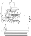
- Figure 1 shows a section of a window 1 comprising a profile 2 of the fixed frame of the window 1 and a profile 3 of the leaf of the window 1, whereby these profiles 2 and 3 are hingeably connected together by means of a hinge 4 that is composed of two hinge leafs 6 and 7 that are connected together by means of a hinge pin 8.
- the hinge 4 is fastened to the profiles 2 and 3 by means of screws 9 that are screwed through appropriate passages 10 in the screw leaves and in passages 11 in the aforementioned profiles 2 and 3.
- the hinge 4 comprises an essentially plate-shaped accessory 12 according that in this case is mounted between the hinge leaf 7 and the profile 3 and which to this end is provided with passages 13 for the screws 9, whereby to this end these passages have the same distance between centres A from one another as the distance between centres A between the passages 10 in the hinge leaf 7.
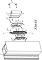
- the accessory 12 is composed of two plate-shaped parts 12a and 12b with sub-passages 13a and 13b for the screws 9.
- the first plate-shaped part 12a is movably affixed by the back 14a onto the hinge leaf 7 along a sliding direction X-X', to which the plate-shaped part 12a concerned is affixed by two opposite edges between two guides, respectively a guide 17 that in the example is formed by a U-shaped folded rib 19 that forms a groove 20 where the movable plate-shaped part 12a concerned is movably held by its edge 15 and a guide 18 that is formed by an upright wall 21 that forms a guide for the edge 16 of the hinge leaf 7 and which in this case is formed by a separate guide element 18 that can be snapped onto a free edge 22 of the hinge leaf 7.
- the snap-fastenable guide 18 is constructed as an L-profile of which one wall forms the aforementioned upright wall 21 and there are elastic lips 24 at a distance from the other wall 23 at the end around a folded edge 25 to form a small hook with which the guide 18 can be snap-fastened behind a groove 26 along the aforementioned edge 22 of the hinge leaf 7, as is best seen in figure 12 .
- the snap-fastenable guide 18 is provided at the ends of a stop wall 27, whereby the distance between the stop walls 27 corresponds to the length of the edge 22, so that in the mounted situation the guide 18 cannot move in the sliding direction X-X'.
- the sub-passages 13a in the plate-shaped part 12a are constructed as slip holes such that, when the hinge 4 is mounted with screws 9, the plate-shaped part 12a remains movable over the length of the slip holes in the sliding direction X-X' with respect to the hinge leaf 7.
- hinge is provided with means that enable the position of the movable plate-shaped element 12a with respect to the hinge leaf 7 to be read.
- these means are formed by a mark 28 in the form of a tooth affixed on the edge 16 of the movable plate-shaped part 12a that is movably held in a rectangular window 29 in the aforementioned upright wall 21 opposite a graduated scale 30 on the outside of the aforementioned upright wall 21.
- the plate-shaped part 12a is provided at both ends with an operating element 31 with an elongated body that can be grasped by the fingers of a fitter and which extends in the aforementioned sliding direction X-X' in line with the plate-shaped element 12a concerned, such that in a mounted situation of the accessory 12 the operating elements 31 remain accessible between the hinge leaf 7 and the aforementioned profile 3 for a manual movement by a fitter, at least insofar the leaf of the window 1 is turned sufficiently open.
- means can be provided to keep the part 12a in position and to be able to move it incrementally with respect to the hinge leaf 7 and thus to provide a resistance against unwanted movement of the part 12a.
- these means are formed by both surfaces being provided with toothing or ribs at certain places where the plate-shaped element 12a is in contact with the hinge leaf 7, such as for example ribs 32 on the back 14 of the plate-shaped element 12a that move opposite ribs 33 on the lips 24, or in the form of ribs 34 opposite a tooth 35 on the upright wall 21 of the guide 18, which is snap-fastened to the hinge leaf 7.
- the second plate-shaped part 12b is provided with sub-passages 13b for the screws 9 in the form of fitted holes with a diameter that is somewhat greater than the diameter of the screws 9 so that in the mounted situation of the accessory, this plate-shaped part 12b concerned is prevented from moving with respect to the hinge leaf 7 by the screws 9, while the first plate-shaped part 12a can move with respect to the second part 12b.
- Both parts 12a and 12b are provided with a relief on the sides turned towards one another, with corresponding wedge-shaped elements 36 and 37 that can best be seen in figures 7 and 8 and which are arranged in series behind one another in the sliding direction X-X' and as it were form toothings extending alongside one another that are located with respect to one another in the sliding direction X-X' according to a slanted pattern.
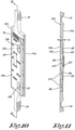
- the toothings that are formed by the wedge-shaped elements 36 and 37 fit into one another and are affixed movably against one another by their oblique sides such as can be seen in the cross-section in figures 9 and 11 in which it can be seen that in figure 11 the teeth are completely moved into one another, while in figure 9 the plate-shaped part 12b is moved upwards with respect to the other part 12a, such that the outermost surfaces 14a and 14b of the accessory 12 are as it were pushed away from one another, which comes down to the thickness D of the accessory 12 in figure 9 being greater than the thickness D of the accessory 12 in figure 11 .
- the oblique sides of the wedge-shaped elements 36 and 37 are provided with ribs 38 that extend in a direction transverse to the aforementioned sliding direction X-X' and which must provide a resistance against the accidental sliding apart of the parts 12a and 12, and in this way form means to incrementally move the plate-shaped parts 12a and 12b with respect to one another and keep them in position.
- the parts 12a and 12b are held together by means of an elastic lip 39 that is affixed to one of the two plate-shaped parts, in this case on part 12b, and which is elastically tightly hooked behind the back 14a of this plate-shaped part 12a via a passage 40 in the other part 12a, or as in the example shown, behind a sloping base of a deepened section 41 in this back 14a.
- the end of the lip 39 is preferably provided with ribs 42 that can mesh with ribs 43 on the base of the deepened section 41.
- hinge 4 The use of a hinge 4 is simple and as follows.
- the hinge is fastened to the profiles 2 and 3 of the fixed frame and the leaf of the window 1 by means of the screws 9, as shown in figure 1 .
- the screws 9 for fastening onto the profile 3 of the leaf are inserted through the passages 10 in the hinge leaf 7 and through the passages 13 in the accessory 12, and screwed tight in the passages 11 in the profile 3, but not completely tightened such that a movement of the movable plate-shaped part 12a of the accessory 12 remains possible.
- the plate-shaped part 12a is moved upwards or downwards by means of an operating element 31 in order to thus move this part 12a of the accessory 12 with respect to the other part 12b of the accessory 12 in order to adjust the thickness D of the accessory 12 in this way according to desire, and thereby also the position of the leaf in the frame of the window 1.
- the screws 9 can be completely tightened such that the parts 12a and 12b of the accessory can no longer move and the thickness of the accessory 12 takes on a fixed value.
- the position of the movable part 12a of the accessory can be read off beforehand by noting the position of the mark 28 with respect to the graduated scale 30, so that when refitting the leaf in the frame the movable part 12a can be brought back to the same position.
- the accessory 12 can also be used separately between a conventional hinge without guides 17 and 18 and a profile 3.
- the accessory can also be used to adjust the distance of the hinge leaf 6 with respect to the profile 2 of the fixed frame.
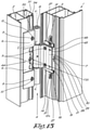
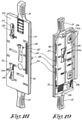
- Figure 13 shows a variant of a hinge according to the invention with a variant embodiment of the accessory 12 as described above, and of an additional accessory 44 to be able to adjust the lateral position of the hinge leaf 6 with respect to the profile 2.
- the first accessory 12 is provided with a guide element 45 that replaces the aforementioned guides 17 and 18 and brings them together into one element in the form of a plate 46 with two parallel guides 17 and 18 thereon in the form of upright walls 19 and 21, between which the plate-shaped part 12a of the connecting piece 12 is movably affixed and is clipped between them by providing the sides of these guides 17 and 18 that are turned towards one another with clips 47.
- the guide element 45 is provided with taps 48 whereby the guide element 45 can be clamped in passages 49 of the hinge leaf 7.
- the guide element 45 is also provided with a window 29 with a graduated scale 30 for the reading of the mark 28, and on the inside of the plate 46 is provided with ribs 33 that can mesh with ribs 32 on the back 14a of the plate-shaped part 12a of the accessory 12.
- the guide element 45 is made as one component of plastic for example by injection moulding so that the clips 47 and taps 48 can be realised in one injection operation.
- the second accessory 44 is intended to adjust the sideways position of the hinge leaf 6 according to a direction Z-Z' transverse to the longitudinal direction of the profile 2.
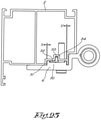
- the hinge leaf 6 is incorporated in a groove 51 of the profile 2 of the fixed frame with a certain sideways play with a thickened section 50.
- the passages 10 for the screws 9 in the hinge leaf 6 are executed in this case as slotted holes 10 that extend along the longitudinal direction of the profile 2, in order to be able to also make a height adjustment of the leaf, and these slotted holes 10 are somewhat larger in width than the diameter of the shank of the screws 9 to enable a sideways movement of the hinge leaf 6.
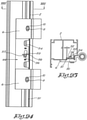
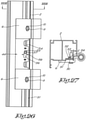
- the second accessory 44 is constructed as a sliding piece 52 that is affixed between the hinge leaf 6 and the profile 2 and which is provided with a guide rib 53 with which the sliding piece 52 is movably affixed in the axial direction in a groove 54 of the profile 2, and which is provided with a peg 55 that is guided in a slot 56 of the hinge leaf 6, whereby this slot 56 runs obliquely with respect to the longitudinal direction of the profile 2.
- the peg 55 and the hinge leaf 6 are provided with horizontal marks 57, respectively 58, that enable their mutual position to be indicated.
- Figures 24 and 25 show a situation whereby the sliding piece 52 is moved downwards with respect to the neutral position of figures 20 and 23 and whereby the thickened section 50 is pushed to the right in the groove 54 to a maximum, whereby the play S is a maximum and the play S' is zero.
Landscapes
- Engineering & Computer Science (AREA)
- Mechanical Engineering (AREA)
- Hinges (AREA)
- Securing Of Glass Panes Or The Like (AREA)
Claims (8)
- Kombination eines Profils (2) und eines Scharniers (4) für ein Fenster oder eine Tür eines Gebäudes, wobei das Scharnier ein Zubehörteil zur seitlichen Einstellung der Position eines Scharnierblatts (6) des Scharniers (4) am Profil (2) des Fensters oder der Tür umfasst, wobei das Profil (2) mit einer ersten Nut (51) und mit einer zweiten Nut (54) versehen ist und das Scharnierblatt (6) mit einer Verdickung (50) versehen ist, die im montierten Zustand der Position des Scharnierblatts (6) am Profil (2) mit einem gewissen seitlichen Spiel in die erste Nut (51) gleitend eingreift, dadurch gekennzeichnet, dass das Scharnierblatt (6) mit einem Schlitz (56) versehen ist, der sich im montierten Zustand des Scharnierblatts (6) am Profil (2) in einer schräg zur Längsrichtung des Profils (2) verlaufenden Richtung erstreckt, und dadurch, dass das Scharnier (4) mit einem als Schiebestück (52) ausgebildeten Zubehörteil (44) versehen ist, das im montierten Zustand des Scharniers (4) am Profil (2) zwischen dem Scharnierblatt (6) und dem Profil (2) befestigt ist, und das mit einer Führungsrippe (53) versehen ist, mit der das Schiebestück (52) beweglich in der zweiten Nut (54) des Profils (2) befestigt ist, und das mit einem Zapfen (55) versehen ist, der im Schlitz (56) des Scharnierblatts (6) geführt wird.
- Kombination nach Anspruch 1, dadurch gekennzeichnet, dass das Scharnierblatt (6) mit Durchgängen (10) zum Befestigen des Scharniers (4) am Profil (2) mithilfe von Schrauben (9) versehen ist und dadurch, dass das Scharnier (4) mit Schrauben (9) zum Befestigen des Scharnierblatts (6) am Profil (2) durch die Durchgänge (10) versehen ist, und dass die Durchgänge (10) etwas größer sind als der Durchmesser des Schaftes der Schrauben (9), um eine seitliche Bewegung des Scharnierblatts (6) auf dem Profil (2) zu ermöglichen.
- Kombination nach Anspruch 2, dadurch gekennzeichnet, dass die Durchgänge (10) als Langlöcher (10) ausgeführt sind, die sich entlang der Längsrichtung des Profils (2) erstrecken, um auch eine Höhenverstellung des Scharnierblatts (6) am Profil (2) zu ermöglichen.
- Kombination nach einem der vorhergehenden Ansprüche, dadurch gekennzeichnet, dass der Zapfen (55) und das Scharnierblatt (6) mit horizontalen Markierungen (57) bzw. (58) versehen sind, die eine Anzeige ihrer Position in Bezug zueinander ermöglichen.
- Kombination nach einem der vorhergehenden Ansprüche, dadurch gekennzeichnet, dass die neutrale seitliche Position des Scharnierblatts (6) einer Position entspricht, bei der die Verdickung (50) des Scharnierblatts (6) etwa mittig in der Nut (54) mit einem Spiel (S, S') auf beiden Seiten der Verdickung (50) liegt.
- Kombination nach einem der vorhergehenden Ansprüche, dadurch gekennzeichnet, dass das Scharnier (4) mit einem zweiten Scharnierblatt (7) zur Befestigung des Scharniers (4) an einem zweiten Profil (3) und mit einem zusätzlichen Zubehörteil (12) zum Einstellen des Abstands zwischen dem zweiten Scharnierblatt (7) und dem zweiten Profil (3) versehen ist, wobei das zusätzliche Zubehörteil (12) aus zwei im Wesentlichen plattenförmigen Teilen (12a und 12b) besteht, die an einer Seite aneinander befestigt sind und die an diesen Seiten in einer bestimmten Gleitrichtung (X-X') in Bezug zueinander beweglich befestigt sind, wobei die aneinander befestigten Seiten jeweils mit einem oder mehreren keilförmigen Elementen (36, 37) versehen sind, die so beschaffen sind, dass sie beim Bewegen beider Teile (12a und 12b) mit ihren keilförmigen Elementen (36, 37) in der einen oder der anderen Richtung entsprechend der vorgenannten Gleitrichtung (X-X') gegeneinander die Dicke (D) des Zubehörteils (12) zu- oder abnimmt, und wobei beide plattenförmigen Teile (12a und 12b) so ausgebildet sind, dass sie im montierten Zustand des Zubehörteils (12) zwischen dem Scharnier (4) und dem zuvor genannten Profil (2, 3) des Fensters (1) oder der Tür manuell und ohne Werkzeug über eine Distanz in Bezug zueinander frei beweglich sind.
- Verwendung einer Kombination nach einem der Ansprüche 2 bis 6 zum Einstellen der Position des Scharniers (4) durch Einstellen der Position des Scharnierblatts (6) auf dem Profil (2), dadurch gekennzeichnet, dass das Scharnier (4) am Profil (2) mithilfe der Schrauben (9) befestigt ist, die durch die Durchgänge (10) in das Profil (2) eingeschraubt sind, und dadurch, dass die seitliche Position des Scharnierblatts (6) bei nicht fest angezogenen Schrauben eingestellt wird durch Bewegen des Zapfens (48) des Schiebestücks (52) je nach der gewünschten seitlichen Position nach oben oder unten im Schlitz (56) und durch Fixieren des Scharnierblatts (6) in der gewünschten Position durch vollständiges Anziehen der Schrauben (9).
- Verwendung nach Anspruch 7, dadurch gekennzeichnet, dass die zuvor genannten Durchgänge (10) als Langlöcher (10) bereitgestellt sind, die sich entlang der Längsrichtung des Profils (2) erstrecken, wobei die Höhenposition des Scharnierblatts (6) auf dem Profil (2) gleichzeitig mit der seitlichen Einstellung des Scharnierblatts (6) durch Auf- oder Abwärtsbewegen des Scharnierblatts (6) eingestellt wird.
Priority Applications (1)
| Application Number | Priority Date | Filing Date | Title |
|---|---|---|---|
| PL19197284T PL3604723T3 (pl) | 2014-08-13 | 2015-07-28 | Połączenie profilu i zawiasu do okna lub drzwi z elementem pomocniczym do regulacji położenia między wspomnianym zawiasem a wspomnianym profilem wymienionego okna lub drzwi |
Applications Claiming Priority (2)
| Application Number | Priority Date | Filing Date | Title |
|---|---|---|---|
| BE2014/0618A BE1022089B1 (nl) | 2014-08-13 | 2014-08-13 | Hulpstuk voor regelen van de afstand tussen een scharnier en een profiel van een raam of deur en scharnier uitgerust met zulk hulpstuk |
| EP15002233.3A EP2993290B1 (de) | 2014-08-13 | 2015-07-28 | Zubehörteil für die verstellung des abstands zwischen einem scharnier und einem profil eines fensters oder einer tür und scharnier mit einem solchen zubehörteil |
Related Parent Applications (2)
| Application Number | Title | Priority Date | Filing Date |
|---|---|---|---|
| EP15002233.3A Division EP2993290B1 (de) | 2014-08-13 | 2015-07-28 | Zubehörteil für die verstellung des abstands zwischen einem scharnier und einem profil eines fensters oder einer tür und scharnier mit einem solchen zubehörteil |
| EP15002233.3A Division-Into EP2993290B1 (de) | 2014-08-13 | 2015-07-28 | Zubehörteil für die verstellung des abstands zwischen einem scharnier und einem profil eines fensters oder einer tür und scharnier mit einem solchen zubehörteil |
Publications (2)
| Publication Number | Publication Date |
|---|---|
| EP3604723A1 EP3604723A1 (de) | 2020-02-05 |
| EP3604723B1 true EP3604723B1 (de) | 2022-02-16 |
Family
ID=52423510
Family Applications (2)
| Application Number | Title | Priority Date | Filing Date |
|---|---|---|---|
| EP19197284.3A Active EP3604723B1 (de) | 2014-08-13 | 2015-07-28 | Kombination eines profils und eines scharniers für ein fenster oder eine tür mit zubehör zur anpassung der position zwischen dem scharnier und dem profil des fensters oder der tür |
| EP15002233.3A Active EP2993290B1 (de) | 2014-08-13 | 2015-07-28 | Zubehörteil für die verstellung des abstands zwischen einem scharnier und einem profil eines fensters oder einer tür und scharnier mit einem solchen zubehörteil |
Family Applications After (1)
| Application Number | Title | Priority Date | Filing Date |
|---|---|---|---|
| EP15002233.3A Active EP2993290B1 (de) | 2014-08-13 | 2015-07-28 | Zubehörteil für die verstellung des abstands zwischen einem scharnier und einem profil eines fensters oder einer tür und scharnier mit einem solchen zubehörteil |
Country Status (5)
| Country | Link |
|---|---|
| EP (2) | EP3604723B1 (de) |
| BE (1) | BE1022089B1 (de) |
| ES (2) | ES2763972T3 (de) |
| PL (2) | PL2993290T3 (de) |
| PT (2) | PT2993290T (de) |
Families Citing this family (5)
| Publication number | Priority date | Publication date | Assignee | Title |
|---|---|---|---|---|
| US11124999B2 (en) | 2019-11-11 | 2021-09-21 | Snap-On Incorporated | Adjustable door hinge mechanism |
| US12291913B2 (en) * | 2020-05-20 | 2025-05-06 | D & D Technologies Pty Ltd | Hinges or the like |
| CN111852256B (zh) * | 2020-07-28 | 2025-12-23 | 福建省德牧卫浴科技有限公司 | 一种可调的门框组件和安装方法及淋浴门安装结构 |
| BE1029466B1 (nl) * | 2021-06-07 | 2023-01-09 | Sobinco Fa | Scharnier voor een raam of een deur met scharnierblad met bijhorend hulpstuk met regelbare dikte voor de zijdelingse regeling van het raam of de deur |
| CN117287101B (zh) * | 2023-02-10 | 2025-10-31 | 广东尚坤工业科技有限公司 | 偏心调节铰链 |
Family Cites Families (8)
| Publication number | Priority date | Publication date | Assignee | Title |
|---|---|---|---|---|
| DE3114660A1 (de) * | 1979-11-22 | 1982-06-24 | Alfred Grass GmbH Metallwarenfabrik, 6973 Höchst, Vorarlberg | Tuerscharnier fuer moebeltueren o.dgl. |
| AT402528B (de) * | 1992-01-31 | 1997-06-25 | Roto Frank Eisenwaren | Seitenverstellbares ladenband |
| DE10212476B4 (de) * | 2002-03-20 | 2004-06-17 | Niemann, Hans Dieter | Verstelleinrichtung eines Drehbandes von Türen oder Fenstern |
| BE1016414A3 (nl) | 2005-01-17 | 2006-10-03 | Parys Remi E Van | Scharnierconstructie. |
| DE102005056850B3 (de) * | 2005-11-28 | 2007-01-18 | Stammschröer, Bernhard | Türband |
| DE202006016738U1 (de) * | 2006-10-30 | 2008-03-13 | Dr. Hahn Gmbh & Co. Kg | Bandanordnung für Türen, Fenster u.dgl. |
| EP2273049A1 (de) * | 2009-07-09 | 2011-01-12 | Dr. Hahn GmbH & Co. KG | Justierbares Band |
| EP2348179A1 (de) * | 2010-01-21 | 2011-07-27 | Fritz Fuhrimann | Scharnierbeschlag für Fensterläden |
-
2014
- 2014-08-13 BE BE2014/0618A patent/BE1022089B1/nl not_active IP Right Cessation
-
2015
- 2015-07-28 PL PL15002233T patent/PL2993290T3/pl unknown
- 2015-07-28 ES ES15002233T patent/ES2763972T3/es active Active
- 2015-07-28 PL PL19197284T patent/PL3604723T3/pl unknown
- 2015-07-28 PT PT150022333T patent/PT2993290T/pt unknown
- 2015-07-28 EP EP19197284.3A patent/EP3604723B1/de active Active
- 2015-07-28 EP EP15002233.3A patent/EP2993290B1/de active Active
- 2015-07-28 PT PT191972843T patent/PT3604723T/pt unknown
- 2015-07-28 ES ES19197284T patent/ES2912002T3/es active Active
Non-Patent Citations (1)
| Title |
|---|
| None * |
Also Published As
| Publication number | Publication date |
|---|---|
| PT3604723T (pt) | 2022-05-04 |
| PT2993290T (pt) | 2020-01-07 |
| EP2993290B1 (de) | 2019-11-13 |
| EP2993290A2 (de) | 2016-03-09 |
| PL3604723T3 (pl) | 2022-06-06 |
| ES2763972T3 (es) | 2020-06-01 |
| PL2993290T3 (pl) | 2020-06-01 |
| EP2993290A3 (de) | 2016-04-13 |
| ES2912002T3 (es) | 2022-05-24 |
| EP3604723A1 (de) | 2020-02-05 |
| BE1022089B1 (nl) | 2016-02-15 |
Similar Documents
| Publication | Publication Date | Title |
|---|---|---|
| EP3604723B1 (de) | Kombination eines profils und eines scharniers für ein fenster oder eine tür mit zubehör zur anpassung der position zwischen dem scharnier und dem profil des fensters oder der tür | |
| US6263632B1 (en) | Adjustable decorative shutter | |
| DK2820222T3 (en) | Covering device for a building and having a positionable handle device | |
| EP2512014B1 (de) | Linearantrieb insbesondere für Schiebetüren, oder für Tür- oder Fensterschliesselemente | |
| KR20100093265A (ko) | 슬라이딩 도어용 연동 개폐장치 | |
| US8833843B2 (en) | Sunroof unit and vehicle with a sunroof unit | |
| CA2549991A1 (en) | Roller shutter box | |
| DK2949855T3 (en) | Door seal, door with door seal and method of manufacture thereof | |
| US20160326787A1 (en) | System and methods for securing a hinge to a frame | |
| US20120260576A1 (en) | Linear actuator particularly for sliding doors | |
| EP3808926B1 (de) | Vorrichtung zur schwenkbaren befestigung eines türflügels an einer türzarge | |
| EP1520955B1 (de) | Klemmträger für Sonnen- und Blickschutzeinrichtungen | |
| AU2018320086B2 (en) | Finger protection device | |
| DE202007011076U1 (de) | Bandanordnung mit Führungsprofil | |
| US8851150B2 (en) | One-piece slide-on sunshade hook | |
| DE102014018562A1 (de) | Verstellbare Abdeckvorrichtung für eine Fläche | |
| EP2789780B1 (de) | Trag- und Stelleinrichtung eines Wagens für Schiebetüren | |
| DE10160802A1 (de) | Automatische Schiebetüranlage mit Seitenprofil | |
| GB2452514A (en) | A cam lock for a window or a door | |
| DE102017203688B4 (de) | Rauchschalterzentrale | |
| EP3523494B1 (de) | Verbundprofil für ein fenster oder eine tür sowie mit solchen profilen montiertes fenster oder tür | |
| DE202010000749U1 (de) | Klemmhalterung mit abgewinkelter Montagefläche | |
| GB2398830A (en) | Adjustable shoot bolt arms lockable by operation of driving mechanism | |
| US20180030777A1 (en) | Gear Driven Louver Shutter System | |
| CN207660428U (zh) | 用于门的齿轨 |
Legal Events
| Date | Code | Title | Description |
|---|---|---|---|
| PUAI | Public reference made under article 153(3) epc to a published international application that has entered the european phase |
Free format text: ORIGINAL CODE: 0009012 |
|
| STAA | Information on the status of an ep patent application or granted ep patent |
Free format text: STATUS: THE APPLICATION HAS BEEN PUBLISHED |
|
| AC | Divisional application: reference to earlier application |
Ref document number: 2993290 Country of ref document: EP Kind code of ref document: P |
|
| AK | Designated contracting states |
Kind code of ref document: A1 Designated state(s): AL AT BE BG CH CY CZ DE DK EE ES FI FR GB GR HR HU IE IS IT LI LT LU LV MC MK MT NL NO PL PT RO RS SE SI SK SM TR |
|
| STAA | Information on the status of an ep patent application or granted ep patent |
Free format text: STATUS: REQUEST FOR EXAMINATION WAS MADE |
|
| 17P | Request for examination filed |
Effective date: 20200302 |
|
| RBV | Designated contracting states (corrected) |
Designated state(s): AL AT BE BG CH CY CZ DE DK EE ES FI FR GB GR HR HU IE IS IT LI LT LU LV MC MK MT NL NO PL PT RO RS SE SI SK SM TR |
|
| STAA | Information on the status of an ep patent application or granted ep patent |
Free format text: STATUS: EXAMINATION IS IN PROGRESS |
|
| 17Q | First examination report despatched |
Effective date: 20200821 |
|
| RAP1 | Party data changed (applicant data changed or rights of an application transferred) |
Owner name: SOBINCO, NAAMLOZE VENNOOTSCHAP |
|
| RIN1 | Information on inventor provided before grant (corrected) |
Inventor name: VAN PARYS, REMI EMIEL |
|
| GRAP | Despatch of communication of intention to grant a patent |
Free format text: ORIGINAL CODE: EPIDOSNIGR1 |
|
| STAA | Information on the status of an ep patent application or granted ep patent |
Free format text: STATUS: GRANT OF PATENT IS INTENDED |
|
| INTG | Intention to grant announced |
Effective date: 20211029 |
|
| GRAS | Grant fee paid |
Free format text: ORIGINAL CODE: EPIDOSNIGR3 |
|
| GRAA | (expected) grant |
Free format text: ORIGINAL CODE: 0009210 |
|
| STAA | Information on the status of an ep patent application or granted ep patent |
Free format text: STATUS: THE PATENT HAS BEEN GRANTED |
|
| AC | Divisional application: reference to earlier application |
Ref document number: 2993290 Country of ref document: EP Kind code of ref document: P |
|
| AK | Designated contracting states |
Kind code of ref document: B1 Designated state(s): AL AT BE BG CH CY CZ DE DK EE ES FI FR GB GR HR HU IE IS IT LI LT LU LV MC MK MT NL NO PL PT RO RS SE SI SK SM TR |
|
| REG | Reference to a national code |
Ref country code: GB Ref legal event code: FG4D |
|
| REG | Reference to a national code |
Ref country code: CH Ref legal event code: EP |
|
| REG | Reference to a national code |
Ref country code: DE Ref legal event code: R096 Ref document number: 602015077027 Country of ref document: DE |
|
| REG | Reference to a national code |
Ref country code: AT Ref legal event code: REF Ref document number: 1468981 Country of ref document: AT Kind code of ref document: T Effective date: 20220315 |
|
| REG | Reference to a national code |
Ref country code: IE Ref legal event code: FG4D Ref country code: NL Ref legal event code: FP |
|
| REG | Reference to a national code |
Ref country code: PT Ref legal event code: SC4A Ref document number: 3604723 Country of ref document: PT Date of ref document: 20220504 Kind code of ref document: T Free format text: AVAILABILITY OF NATIONAL TRANSLATION Effective date: 20220427 |
|
| REG | Reference to a national code |
Ref country code: ES Ref legal event code: FG2A Ref document number: 2912002 Country of ref document: ES Kind code of ref document: T3 Effective date: 20220524 |
|
| REG | Reference to a national code |
Ref country code: LT Ref legal event code: MG9D |
|
| PG25 | Lapsed in a contracting state [announced via postgrant information from national office to epo] |
Ref country code: SE Free format text: LAPSE BECAUSE OF FAILURE TO SUBMIT A TRANSLATION OF THE DESCRIPTION OR TO PAY THE FEE WITHIN THE PRESCRIBED TIME-LIMIT Effective date: 20220216 Ref country code: RS Free format text: LAPSE BECAUSE OF FAILURE TO SUBMIT A TRANSLATION OF THE DESCRIPTION OR TO PAY THE FEE WITHIN THE PRESCRIBED TIME-LIMIT Effective date: 20220216 Ref country code: NO Free format text: LAPSE BECAUSE OF FAILURE TO SUBMIT A TRANSLATION OF THE DESCRIPTION OR TO PAY THE FEE WITHIN THE PRESCRIBED TIME-LIMIT Effective date: 20220516 Ref country code: LT Free format text: LAPSE BECAUSE OF FAILURE TO SUBMIT A TRANSLATION OF THE DESCRIPTION OR TO PAY THE FEE WITHIN THE PRESCRIBED TIME-LIMIT Effective date: 20220216 Ref country code: HR Free format text: LAPSE BECAUSE OF FAILURE TO SUBMIT A TRANSLATION OF THE DESCRIPTION OR TO PAY THE FEE WITHIN THE PRESCRIBED TIME-LIMIT Effective date: 20220216 Ref country code: BG Free format text: LAPSE BECAUSE OF FAILURE TO SUBMIT A TRANSLATION OF THE DESCRIPTION OR TO PAY THE FEE WITHIN THE PRESCRIBED TIME-LIMIT Effective date: 20220516 |
|
| PG25 | Lapsed in a contracting state [announced via postgrant information from national office to epo] |
Ref country code: LV Free format text: LAPSE BECAUSE OF FAILURE TO SUBMIT A TRANSLATION OF THE DESCRIPTION OR TO PAY THE FEE WITHIN THE PRESCRIBED TIME-LIMIT Effective date: 20220216 Ref country code: GR Free format text: LAPSE BECAUSE OF FAILURE TO SUBMIT A TRANSLATION OF THE DESCRIPTION OR TO PAY THE FEE WITHIN THE PRESCRIBED TIME-LIMIT Effective date: 20220517 Ref country code: FI Free format text: LAPSE BECAUSE OF FAILURE TO SUBMIT A TRANSLATION OF THE DESCRIPTION OR TO PAY THE FEE WITHIN THE PRESCRIBED TIME-LIMIT Effective date: 20220216 |
|
| PG25 | Lapsed in a contracting state [announced via postgrant information from national office to epo] |
Ref country code: IS Free format text: LAPSE BECAUSE OF FAILURE TO SUBMIT A TRANSLATION OF THE DESCRIPTION OR TO PAY THE FEE WITHIN THE PRESCRIBED TIME-LIMIT Effective date: 20220617 |
|
| PG25 | Lapsed in a contracting state [announced via postgrant information from national office to epo] |
Ref country code: SM Free format text: LAPSE BECAUSE OF FAILURE TO SUBMIT A TRANSLATION OF THE DESCRIPTION OR TO PAY THE FEE WITHIN THE PRESCRIBED TIME-LIMIT Effective date: 20220216 Ref country code: SK Free format text: LAPSE BECAUSE OF FAILURE TO SUBMIT A TRANSLATION OF THE DESCRIPTION OR TO PAY THE FEE WITHIN THE PRESCRIBED TIME-LIMIT Effective date: 20220216 Ref country code: RO Free format text: LAPSE BECAUSE OF FAILURE TO SUBMIT A TRANSLATION OF THE DESCRIPTION OR TO PAY THE FEE WITHIN THE PRESCRIBED TIME-LIMIT Effective date: 20220216 Ref country code: EE Free format text: LAPSE BECAUSE OF FAILURE TO SUBMIT A TRANSLATION OF THE DESCRIPTION OR TO PAY THE FEE WITHIN THE PRESCRIBED TIME-LIMIT Effective date: 20220216 Ref country code: DK Free format text: LAPSE BECAUSE OF FAILURE TO SUBMIT A TRANSLATION OF THE DESCRIPTION OR TO PAY THE FEE WITHIN THE PRESCRIBED TIME-LIMIT Effective date: 20220216 Ref country code: CZ Free format text: LAPSE BECAUSE OF FAILURE TO SUBMIT A TRANSLATION OF THE DESCRIPTION OR TO PAY THE FEE WITHIN THE PRESCRIBED TIME-LIMIT Effective date: 20220216 |
|
| REG | Reference to a national code |
Ref country code: DE Ref legal event code: R097 Ref document number: 602015077027 Country of ref document: DE |
|
| PG25 | Lapsed in a contracting state [announced via postgrant information from national office to epo] |
Ref country code: AL Free format text: LAPSE BECAUSE OF FAILURE TO SUBMIT A TRANSLATION OF THE DESCRIPTION OR TO PAY THE FEE WITHIN THE PRESCRIBED TIME-LIMIT Effective date: 20220216 |
|
| PLBE | No opposition filed within time limit |
Free format text: ORIGINAL CODE: 0009261 |
|
| STAA | Information on the status of an ep patent application or granted ep patent |
Free format text: STATUS: NO OPPOSITION FILED WITHIN TIME LIMIT |
|
| 26N | No opposition filed |
Effective date: 20221117 |
|
| REG | Reference to a national code |
Ref country code: AT Ref legal event code: UEP Ref document number: 1468981 Country of ref document: AT Kind code of ref document: T Effective date: 20220216 |
|
| PG25 | Lapsed in a contracting state [announced via postgrant information from national office to epo] |
Ref country code: SI Free format text: LAPSE BECAUSE OF FAILURE TO SUBMIT A TRANSLATION OF THE DESCRIPTION OR TO PAY THE FEE WITHIN THE PRESCRIBED TIME-LIMIT Effective date: 20220216 Ref country code: MC Free format text: LAPSE BECAUSE OF FAILURE TO SUBMIT A TRANSLATION OF THE DESCRIPTION OR TO PAY THE FEE WITHIN THE PRESCRIBED TIME-LIMIT Effective date: 20220216 |
|
| REG | Reference to a national code |
Ref country code: CH Ref legal event code: PL |
|
| PG25 | Lapsed in a contracting state [announced via postgrant information from national office to epo] |
Ref country code: LU Free format text: LAPSE BECAUSE OF NON-PAYMENT OF DUE FEES Effective date: 20220728 Ref country code: LI Free format text: LAPSE BECAUSE OF NON-PAYMENT OF DUE FEES Effective date: 20220731 Ref country code: CH Free format text: LAPSE BECAUSE OF NON-PAYMENT OF DUE FEES Effective date: 20220731 |
|
| P01 | Opt-out of the competence of the unified patent court (upc) registered |
Effective date: 20230530 |
|
| PG25 | Lapsed in a contracting state [announced via postgrant information from national office to epo] |
Ref country code: IE Free format text: LAPSE BECAUSE OF NON-PAYMENT OF DUE FEES Effective date: 20220728 |
|
| PG25 | Lapsed in a contracting state [announced via postgrant information from national office to epo] |
Ref country code: HU Free format text: LAPSE BECAUSE OF FAILURE TO SUBMIT A TRANSLATION OF THE DESCRIPTION OR TO PAY THE FEE WITHIN THE PRESCRIBED TIME-LIMIT; INVALID AB INITIO Effective date: 20150728 |
|
| PG25 | Lapsed in a contracting state [announced via postgrant information from national office to epo] |
Ref country code: MK Free format text: LAPSE BECAUSE OF FAILURE TO SUBMIT A TRANSLATION OF THE DESCRIPTION OR TO PAY THE FEE WITHIN THE PRESCRIBED TIME-LIMIT Effective date: 20220216 Ref country code: CY Free format text: LAPSE BECAUSE OF FAILURE TO SUBMIT A TRANSLATION OF THE DESCRIPTION OR TO PAY THE FEE WITHIN THE PRESCRIBED TIME-LIMIT Effective date: 20220216 |
|
| PG25 | Lapsed in a contracting state [announced via postgrant information from national office to epo] |
Ref country code: MT Free format text: LAPSE BECAUSE OF FAILURE TO SUBMIT A TRANSLATION OF THE DESCRIPTION OR TO PAY THE FEE WITHIN THE PRESCRIBED TIME-LIMIT Effective date: 20220216 |
|
| PGFP | Annual fee paid to national office [announced via postgrant information from national office to epo] |
Ref country code: PT Payment date: 20250625 Year of fee payment: 11 |
|
| PGFP | Annual fee paid to national office [announced via postgrant information from national office to epo] |
Ref country code: NL Payment date: 20250723 Year of fee payment: 11 |
|
| PGFP | Annual fee paid to national office [announced via postgrant information from national office to epo] |
Ref country code: ES Payment date: 20250819 Year of fee payment: 11 |
|
| PGFP | Annual fee paid to national office [announced via postgrant information from national office to epo] |
Ref country code: DE Payment date: 20250722 Year of fee payment: 11 |
|
| PGFP | Annual fee paid to national office [announced via postgrant information from national office to epo] |
Ref country code: PL Payment date: 20250721 Year of fee payment: 11 Ref country code: IT Payment date: 20250731 Year of fee payment: 11 |
|
| PGFP | Annual fee paid to national office [announced via postgrant information from national office to epo] |
Ref country code: BE Payment date: 20250722 Year of fee payment: 11 Ref country code: GB Payment date: 20250724 Year of fee payment: 11 |
|
| PGFP | Annual fee paid to national office [announced via postgrant information from national office to epo] |
Ref country code: FR Payment date: 20250723 Year of fee payment: 11 Ref country code: AT Payment date: 20250721 Year of fee payment: 11 |
|
| PG25 | Lapsed in a contracting state [announced via postgrant information from national office to epo] |
Ref country code: TR Free format text: LAPSE BECAUSE OF FAILURE TO SUBMIT A TRANSLATION OF THE DESCRIPTION OR TO PAY THE FEE WITHIN THE PRESCRIBED TIME-LIMIT Effective date: 20220216 |