EP3604745A2 - Soupape de vapeur résistant à l'érosion - Google Patents
Soupape de vapeur résistant à l'érosion Download PDFInfo
- Publication number
- EP3604745A2 EP3604745A2 EP19188488.1A EP19188488A EP3604745A2 EP 3604745 A2 EP3604745 A2 EP 3604745A2 EP 19188488 A EP19188488 A EP 19188488A EP 3604745 A2 EP3604745 A2 EP 3604745A2
- Authority
- EP
- European Patent Office
- Prior art keywords
- nose piece
- valve
- pressure seal
- seal head
- cavity
- Prior art date
- Legal status (The legal status is an assumption and is not a legal conclusion. Google has not performed a legal analysis and makes no representation as to the accuracy of the status listed.)
- Granted
Links
Images


Classifications
-
- F—MECHANICAL ENGINEERING; LIGHTING; HEATING; WEAPONS; BLASTING
- F16—ENGINEERING ELEMENTS AND UNITS; GENERAL MEASURES FOR PRODUCING AND MAINTAINING EFFECTIVE FUNCTIONING OF MACHINES OR INSTALLATIONS; THERMAL INSULATION IN GENERAL
- F16K—VALVES; TAPS; COCKS; ACTUATING-FLOATS; DEVICES FOR VENTING OR AERATING
- F16K1/00—Lift valves or globe valves, i.e. cut-off apparatus with closure members having at least a component of their opening and closing motion perpendicular to the closing faces
- F16K1/32—Details
- F16K1/34—Cutting-off parts, e.g. valve members, seats
- F16K1/36—Valve members
-
- F—MECHANICAL ENGINEERING; LIGHTING; HEATING; WEAPONS; BLASTING
- F16—ENGINEERING ELEMENTS AND UNITS; GENERAL MEASURES FOR PRODUCING AND MAINTAINING EFFECTIVE FUNCTIONING OF MACHINES OR INSTALLATIONS; THERMAL INSULATION IN GENERAL
- F16K—VALVES; TAPS; COCKS; ACTUATING-FLOATS; DEVICES FOR VENTING OR AERATING
- F16K25/00—Details relating to contact between valve members and seats
- F16K25/04—Arrangements for preventing erosion, not otherwise provided for
-
- F—MECHANICAL ENGINEERING; LIGHTING; HEATING; WEAPONS; BLASTING
- F01—MACHINES OR ENGINES IN GENERAL; ENGINE PLANTS IN GENERAL; STEAM ENGINES
- F01D—NON-POSITIVE DISPLACEMENT MACHINES OR ENGINES, e.g. STEAM TURBINES
- F01D17/00—Regulating or controlling by varying flow
- F01D17/10—Final actuators
- F01D17/12—Final actuators arranged in stator parts
- F01D17/14—Final actuators arranged in stator parts varying effective cross-sectional area of nozzles or guide conduits
- F01D17/141—Final actuators arranged in stator parts varying effective cross-sectional area of nozzles or guide conduits by means of shiftable members or valves obturating part of the flow path
- F01D17/145—Final actuators arranged in stator parts varying effective cross-sectional area of nozzles or guide conduits by means of shiftable members or valves obturating part of the flow path by means of valves, e.g. for steam turbines
-
- F—MECHANICAL ENGINEERING; LIGHTING; HEATING; WEAPONS; BLASTING
- F16—ENGINEERING ELEMENTS AND UNITS; GENERAL MEASURES FOR PRODUCING AND MAINTAINING EFFECTIVE FUNCTIONING OF MACHINES OR INSTALLATIONS; THERMAL INSULATION IN GENERAL
- F16K—VALVES; TAPS; COCKS; ACTUATING-FLOATS; DEVICES FOR VENTING OR AERATING
- F16K1/00—Lift valves or globe valves, i.e. cut-off apparatus with closure members having at least a component of their opening and closing motion perpendicular to the closing faces
- F16K1/32—Details
- F16K1/34—Cutting-off parts, e.g. valve members, seats
- F16K1/36—Valve members
- F16K1/38—Valve members of conical shape
- F16K1/385—Valve members of conical shape contacting in the closed position, over a substantial axial length, a seat surface having the same inclination
-
- F—MECHANICAL ENGINEERING; LIGHTING; HEATING; WEAPONS; BLASTING
- F16—ENGINEERING ELEMENTS AND UNITS; GENERAL MEASURES FOR PRODUCING AND MAINTAINING EFFECTIVE FUNCTIONING OF MACHINES OR INSTALLATIONS; THERMAL INSULATION IN GENERAL
- F16K—VALVES; TAPS; COCKS; ACTUATING-FLOATS; DEVICES FOR VENTING OR AERATING
- F16K25/00—Details relating to contact between valve members and seats
- F16K25/005—Particular materials for seats or closure elements
-
- F—MECHANICAL ENGINEERING; LIGHTING; HEATING; WEAPONS; BLASTING
- F16—ENGINEERING ELEMENTS AND UNITS; GENERAL MEASURES FOR PRODUCING AND MAINTAINING EFFECTIVE FUNCTIONING OF MACHINES OR INSTALLATIONS; THERMAL INSULATION IN GENERAL
- F16K—VALVES; TAPS; COCKS; ACTUATING-FLOATS; DEVICES FOR VENTING OR AERATING
- F16K27/00—Construction of housing; Use of materials therefor
- F16K27/02—Construction of housing; Use of materials therefor of lift valves
-
- F—MECHANICAL ENGINEERING; LIGHTING; HEATING; WEAPONS; BLASTING
- F16—ENGINEERING ELEMENTS AND UNITS; GENERAL MEASURES FOR PRODUCING AND MAINTAINING EFFECTIVE FUNCTIONING OF MACHINES OR INSTALLATIONS; THERMAL INSULATION IN GENERAL
- F16K—VALVES; TAPS; COCKS; ACTUATING-FLOATS; DEVICES FOR VENTING OR AERATING
- F16K37/00—Special means in or on valves or other cut-off apparatus for indicating or recording operation thereof, or for enabling an alarm to be given
-
- F—MECHANICAL ENGINEERING; LIGHTING; HEATING; WEAPONS; BLASTING
- F05—INDEXING SCHEMES RELATING TO ENGINES OR PUMPS IN VARIOUS SUBCLASSES OF CLASSES F01-F04
- F05D—INDEXING SCHEME FOR ASPECTS RELATING TO NON-POSITIVE-DISPLACEMENT MACHINES OR ENGINES, GAS-TURBINES OR JET-PROPULSION PLANTS
- F05D2220/00—Application
- F05D2220/30—Application in turbines
- F05D2220/31—Application in turbines in steam turbines
-
- F—MECHANICAL ENGINEERING; LIGHTING; HEATING; WEAPONS; BLASTING
- F05—INDEXING SCHEMES RELATING TO ENGINES OR PUMPS IN VARIOUS SUBCLASSES OF CLASSES F01-F04
- F05D—INDEXING SCHEME FOR ASPECTS RELATING TO NON-POSITIVE-DISPLACEMENT MACHINES OR ENGINES, GAS-TURBINES OR JET-PROPULSION PLANTS
- F05D2300/00—Materials; Properties thereof
- F05D2300/10—Metals, alloys or intermetallic compounds
- F05D2300/13—Refractory metals, i.e. Ti, V, Cr, Zr, Nb, Mo, Hf, Ta, W
- F05D2300/132—Chromium
-
- F—MECHANICAL ENGINEERING; LIGHTING; HEATING; WEAPONS; BLASTING
- F05—INDEXING SCHEMES RELATING TO ENGINES OR PUMPS IN VARIOUS SUBCLASSES OF CLASSES F01-F04
- F05D—INDEXING SCHEME FOR ASPECTS RELATING TO NON-POSITIVE-DISPLACEMENT MACHINES OR ENGINES, GAS-TURBINES OR JET-PROPULSION PLANTS
- F05D2300/00—Materials; Properties thereof
- F05D2300/10—Metals, alloys or intermetallic compounds
- F05D2300/13—Refractory metals, i.e. Ti, V, Cr, Zr, Nb, Mo, Hf, Ta, W
- F05D2300/133—Titanium
-
- F—MECHANICAL ENGINEERING; LIGHTING; HEATING; WEAPONS; BLASTING
- F16—ENGINEERING ELEMENTS AND UNITS; GENERAL MEASURES FOR PRODUCING AND MAINTAINING EFFECTIVE FUNCTIONING OF MACHINES OR INSTALLATIONS; THERMAL INSULATION IN GENERAL
- F16K—VALVES; TAPS; COCKS; ACTUATING-FLOATS; DEVICES FOR VENTING OR AERATING
- F16K1/00—Lift valves or globe valves, i.e. cut-off apparatus with closure members having at least a component of their opening and closing motion perpendicular to the closing faces
- F16K1/16—Lift valves or globe valves, i.e. cut-off apparatus with closure members having at least a component of their opening and closing motion perpendicular to the closing faces with pivoted closure-members
- F16K1/18—Lift valves or globe valves, i.e. cut-off apparatus with closure members having at least a component of their opening and closing motion perpendicular to the closing faces with pivoted closure-members with pivoted discs or flaps
- F16K1/22—Lift valves or globe valves, i.e. cut-off apparatus with closure members having at least a component of their opening and closing motion perpendicular to the closing faces with pivoted closure-members with pivoted discs or flaps with axis of rotation crossing the valve member, e.g. butterfly valves
- F16K1/226—Shaping or arrangements of the sealing
- F16K1/2263—Shaping or arrangements of the sealing the sealing being arranged on the valve seat
-
- F—MECHANICAL ENGINEERING; LIGHTING; HEATING; WEAPONS; BLASTING
- F16—ENGINEERING ELEMENTS AND UNITS; GENERAL MEASURES FOR PRODUCING AND MAINTAINING EFFECTIVE FUNCTIONING OF MACHINES OR INSTALLATIONS; THERMAL INSULATION IN GENERAL
- F16K—VALVES; TAPS; COCKS; ACTUATING-FLOATS; DEVICES FOR VENTING OR AERATING
- F16K1/00—Lift valves or globe valves, i.e. cut-off apparatus with closure members having at least a component of their opening and closing motion perpendicular to the closing faces
- F16K1/32—Details
- F16K1/34—Cutting-off parts, e.g. valve members, seats
- F16K1/42—Valve seats
- F16K1/422—Valve seats attachable by a threaded connection to the housing
Definitions
- the present subject matter relates generally to a steam valve for a steam turbine, or more particularly, to a steam valve having an erosion resistant pressure seal head (i.e., valve stem guide).
- an erosion resistant pressure seal head i.e., valve stem guide
- Solid particle erosion is a common problem affecting steam power production components in the power generation industry. Many parts of the steam path between the power boiler and steam turbine are subject to material erosion problems due to entrained magnetite particles exfoliated from boiler tubes into the steam transport system. Over time, erosion damage can accumulate and impact steam piping integrity, valve operation, steam turbine blades, etc. resulting in a loss of plant efficiency, as well as lower reliability and availability due to increase forced outages to repair damaged components. Ultimately, the plant owner will recognize an increasing loss in revenues and profitability.
- a known steam valve generally designated 10
- a control valve actuator (not shown) is coupled to a stem 36 for raising and lowering the control valve head 18 to selectively engage a valve seat 21 for controlling the steam flow through the valve 10. It will be appreciated that the position of the flow control head 18 relative to the valve seat 21 can be controlled in response to load changes on a turbine.
- the control head 18 is annular in configuration, having a hollow or recess 40 along its underside.
- the annular lower edge of control valve head 18 in a closed position, as shown in Fig. 1 engages and seals against the valve seat 21.
- the stop valve head 20 is configured for reception within the recess 40 and also includes an annular surface 41 about its underside for sealing and engaging against the valve seat 21 in a stop valve closed position.
- the stop valve head 20 is mounted on a shaft or stem 44 which extends through a pressure seal head 35 to a hydraulic cylinder (not shown).
- the stop valve head 20 follows the movement of the control valve head 18 through a control system (not shown). By following the movement of the control valve 17, the combination of the control valve head 18 and stop valve head 20 provide a smooth, laminar flow of steam past those heads and through the valve to the outlet 16.
- Fig. 2 illustrates both the control valve head 18 and stop valve head 20 of Fig. 1 in an open position.
- an outlet passage 50 is provided which directs the flow of steam passing through the valve to the outlet 16.
- the outlet passage 50 and the valve seat 21 have walls substantially forming a smooth, continuous transition therebetween without any abrupt changes in flow direction. In this manner, the steam flowing through the valve 10 past the valve seat 21 and through the outlet passage 50 to the outlet 16 is substantially without vortices and affords optimum steam flow characteristics, with minimum losses.
- the outlet passage 50 has a cross-sectional area which is not substantially larger than the cross-sectional area of the valve seat 21 and the outlet 16.
- the pattern of steam flow in the valve-open condition tends toward a laminar flow without substantial vortices and, consequently, with minimum head losses.
- This laminar flow may include entrained solid particles that when passing through the outlet passage, impinge upon the upper tip of the pressure seal head 35 resulting in severe erosion.
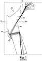
- a schematic view of the steam valve 10 in a partially open position shows a high velocity annular steam flow 54 passing between the control valve head 18 and the valve seat 21, particularly when the spacing therebetween is narrow such as during the transition period when the control valve seat 18 or stop valve head 20 is lifting from or engaging the valve seat 21.
- the high velocity steam 54 annularly impacts the tip of the pressure seal heat 35, for example, at area 42.
- any particle entrained in the steam flow 54 will increase erosion of the pressure seal head 35 at this area 42.
- the present disclosure is directed to a pressure seal head of a steam valve including an elongated body having a bore extending longitudinally through the body, and a nose piece extending from an end of the elongated body.
- the nose piece has at least a tapered end portion and a bore extending longitudinally therethrough.
- the nose piece is configured to longitudinally aligned the bore of the nose piece with the bore of the elongated body.
- the nose piece is formed of a first material which has greater erosion properties than a second material forming the elongated body
- a steam valve in another aspect, is directed to a steam valve includes a housing defining a steam inlet and steam outlet in fluid communication with a valve cavity, and an annular valve seat disposed within the valve cavity.
- a control valve having a valve head coupled to a control valve stem is configured to selectively engage the valve seat.
- the steam valve further includes a stop valve, having a stop valve head, and a stop valve stem coupled to the stop valve head.
- the stop valve is configured to selectively engage the valve seat.
- the steam valve includes a pressure seal head configured to receive the stop valve stem.
- the pressure seal head includes an elongated body having a bore extending longitudinally through the body; and a nose piece extending from an end of the elongated body.
- the nose piece has at least a tapered end portion and a bore extending longitudinally therethrough.
- the nose piece is configured to longitudinally align the bore of the nose piece with the bore of the elongated body.
- the nose piece is formed of a first material which has greater erosion properties than a second material forming the elongated body
- the present disclosure is directed to a nose piece of a pressure seal head of a steam valve.
- the nose piece includes at least a tapered end portion and a bore extending longitudinally therethrough and configured to longitudinally aligned with a bore of an elongated body of the pressure seal head.
- the nose piece is configured to removably and replaceably attach to then elongated body of the pressure seal.
- first, second, and third may be used interchangeably to distinguish one component from another and are not intended to signify location or importance of the individual components.
- upstream and downstream refer to the relative direction with respect to fluid flow in a fluid pathway.
- upstream refers to the direction from which the fluid flows
- downstream refers to the direction to which the fluid flows.
- upper, lower, upward, and downward refer to the relative position of features of a component or direction with respect to its orientation in the illustration of the component and are not intended to signify orientation of the features or direction during the use of the components.
- integral and unitary refer to at least two components which are metallurgically joined or formed together, such that the separation of the components is not easily performed without damaging a component.
- Coupled refers to both direct coupling, fixing, or attaching, as well as indirect coupling, fixing, or attaching through one or more intermediate components or features, unless otherwise specified herein.
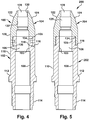
- Fig. 4 shows an exemplary embodiment of a pressure seal head 100 of the present invention for use in the steam valve 10 of Fig. 1 .
- the pressure seal head 100 includes a body 102 and a nose piece 104 attached to the body to enable the nose piece to be removed and replaced without damaging the body.
- the nose piece 104 is formed of high erosion resistant material such as a high chromium alloy, cobalt based alloy, cobalt/chromium alloy, tungsten alloy, titanium alloy or any other high erosion resistant material.
- the nose piece 104 may be formed of Stellite 6B.
- the body 102 may be formed of the same or similar material as the nose piece 104, however, to reduce costs, the body may be formed of a material having less erosion resistant characteristics than the material of the nose piece, such as a low chromium alloy, for example.
- the body 102 may be generally cylindrical in shape having a bore 106 passing longitudinally or axially through the body for slidably receiving the stem 44 of the stop valve 19 of Fig.1 .
- the bore 106 defines an inner surface 103 of the body 102 having a recess 108 to accommodate a sleeve bushing (not shown) to provide a bearing surface for the stem 44.
- the body 102 includes an annular ridge 112 extending from the outer surface 110 for engaging the housing 12 (as best shown in Fig. 1 ) to provide support and a stop to ensure the body extends within the internal cavity 13 of the steam valve 10 at a desired height.
- a lower end 114 of the body 102 is configured to extend into and/or through a bore in the housing 12.
- the upper end 105 of the body 102 has an outer diameter less than the outer diameter of the outer surface 110 to provide an annular step 116, which may provide a seat for the nose piece 104.
- the upper end 105 of the body 102 may include an annular groove 118 for engaging the nose piece 104.
- the nose piece 104 may be shaped to include a lower portion 120 having a generally cylindrical shape and a generally tapered upper portion 122.
- the outer diameter or shape of the lower portion 120 may be substantially the same as the outer surface 110 of the body 102 to provide a relatively smooth transition therebetween.
- the outer surface 124 of the tapered portion 122 of the nose piece 104 may be arcuate, rounded, flat or any other characteristic to provide the desired aerodynamic profile for engaging the steam flow 54 ( Fig. 3 ) passing over the pressure seal head 100.
- the tapered upper portion 122 of the nose piece 104 may have a rounded, convex surface 124.
- the nose piece 104 includes a bore 128 defines an inner surface 130 of the nose piece and passes longitudinally or axially therethrough for slidably receiving the stem 44 of the stop valve 19.
- the bore 106 of the nose piece 104 includes a recess 132 to accommodate a sleeve bushing (not shown) to provide a bearing surface for the stem 44.
- the lower portion 120 of the nose piece 104 includes a counterbore 134 having a diameter that is substantially equal to or less than the outer diameter of the upper end 105 of the body 102 for receiving the body therein.
- the lower end 120 within the counter bore 134 may include an annular ridge 136 extending inwardly having a complimentary shape as the groove 118 in the body.
- the nose piece 104 may be attached to the body 102 by shrink fitting the nose piece to the body whereby the nose piece fits over the upper end 105 of the body and the annular ridge 136 of the noise piece locks into the groove 118 of the body to form the pressure seal head 100.
- at least one pin 140 may extend through a through hole in the nose piece into a hole in the upper end 105 of the body 102.
- the invention also contemplates the nose piece 104 providing no annular ridge 136 nor the body 102 providing a groove 118, whereby the nose piece 104 is simply secured to the body 102 by the at least one pin 140, which is removable.
- the invention further contemplates that one to four pins 140 may be used to secure the nose piece 104 to the body 102 to form the pressure seal head 100.
- a pressure seal head 200 is shown, which is similar to the pressure seal head 100 of Fig. 4 , and therefore, the common features will have the same reference number and characteristics.
- the primary difference between the pressure seal head 200 and the pressure seal head 100 is the means to attach the nose piece to the body to enable removal and/or replacement of the nose piece.
- both the outer surface of the upper portion 105 of the body 202 and the inner surface of the counterbore 134 of the lower portion 120 of the nose piece 104 are threaded.
- the nose piece 204 and the body 202 are threaded together to secure these components together.
- the present invention contemplates these attachment features may be reversed whereby the nose piece 104, 204 and the body 102, 202 are attached together by inserting the nose piece into the body, such that the nosepiece 104, 204 includes the male portion of the attachment and the body 102, 202 includes the female portion.
- the upper portion 105 of the bodies 102, 202 may include a counterbore similar to the counterbore 134 of the respective nose piece 104, 204 of Figs.
- the lower portion 120 of the nose pieces 104, 204 may include a lower end with an outer diameter less than the outer diameter of the outer surface of the nose piece 104, 204 to provide an annular step similar to the upper end 105 of the respective bodies 102, 202 of Figs. 4 and 5 .
- This alternative embodiment for the pressure seal head 100 of Fig. 4 may include a complementary annular ridge and groove to attach the nose piece into the body.
- this alternative embodiment for the pressure seal head 200 of Fig. 5 may include threaded surfaces on the lower end of the nose piece and the counterbore of the body to thread and secure the nose piece into the body.
- the noise piece 104, 204 and body 102, 202 are described as having a generally cylindrical shape or circular cross-section, one will appreciate the shape or cross-section may include any shape or cross-section, for example any hexagonal shape.
- the pressure seal head 300 includes a body 302 and a nose piece 304 fixedly attached together. Similar to the pressure seal heads 100, 200, the nose piece 304 is formed of high erosion resistant material, while the body may be formed may be formed of a material having less erosion resistant characteristics than the material of the nose piece, such as a low chromium alloy, for example.
- the primary difference between the pressure seal head 300 and the pressure seal heads 100, 200 is the means to attach the body 302 and nose piece 304 together.
- the body 302 and the nose piece 304 may be formed or joined together to form an integral or unitary component by various attachment methods or means, such as conventional brazing or welding (e.g., inertia welding) attachment methods.
- the nose piece 304 and body 302 may be formed as a unitary component by molding or additive manufacturing methods, including dissimilar additive manufacturing methods.
- the nose piece 304 and body 302 provide complementary flat engagement surfaces 306, 308 respectively, to provide a planar transition between the components. While the engagement surfaces are flat, one will appreciate the engagement surfaces by provide complementary interlocking features.
- the upper end of the body 302 may extend into a complementary bore within the nose piece 304, or vice versa.
- the non-destructive removal and replacement of the nose piece 304 from the body 302 is not simple nor economical, and therefore, replacement of entire pressure seal head 300 is the most practicable.
- Figs. 7 and 8 illustrate a nose piece 404 similar to the nose piece 104 of the pressure seal head 100 of Fig. 4 modified to include a wear indicator 410 to provide a means to notify an operator that the outer surface of the nose piece 404 has excessive erosion.
- the common features, therefore, will have the same reference number.
- the nose piece 404 may include at least one cavity 412 disposed within the tapered portion 112 where the nose piece may experience the greatest amount of erosion at area 42, as illustrated in Fig. 3 .
- the cavity 412 may extend from the tip 414 of the nose piece 404 to at least the bottom of the tapered portion 120 of the nose piece 404.
- the cavity 410 is in fluid communication with an opening or slot 416 disposed in the inner surface of the lower portion 120 of the nose piece 404.
- the cavity 412 is spaced from the outer surface of the nose piece 400 to provide an inner wall 415 and an outer wall 415 having a desired outer wall thickness t 1 , as best shown in Fig. 8 .
- the thickness t 1 of the outer wall 414 is indicative of the amount of acceptable erosion for the specific area 42 (see Figs. 2 and 3 ) on the nose piece 404. As shown, the thickness of the outer wall 414 of the nose piece 404 may be increasing greater as the cavity 412 extends downward.
- the invention further contemplates the thickness of the outer wall to remain constant over the tapered portion 122 of the nose piece 412, or the thickness of the outer wall over the tapered portion 122 decreasingly as the cavity 412 extends downward. Further, the thickness of the outer wall may vary depending on the erosion pattern on the nose piece 404. For example, the wall thickness may be greatest at the area 42 experiencing the most erosion. As best shown in Fig. 8 , the cavity 412 further extends circumferentially about a portion of the nose piece 404, as shown, or completely around the entire circumference of the nose piece. In the embodiment shown in Figs.
- the nose piece 404 includes four cavities 412 evenly spaced, circumferentially around the nose piece 404, with each cavity in fluid communication with a respective slot 416.
- any number of cavities 412 may be disposed circumferentially within the nose piece 404.
- the spacing 420 between the cavities 412 is minimal to minimize the circumferential area void of the wear indicator.
- the cavities 412 may have different varying circumferential widths or the same circumferential widths.
- the wear indicator system 410 further includes a sensor (not shown) for measuring the pressure within the bore 128,106 and outside of surface 124 and 122 of the pressure seal head 100.
- a control system (not shown) provides an alarm or indicator to an operator that the nose piece 100 indicating the excessive erosion, and therefore, replacement of the nose piece 404 may be needed.
- each of the nose pieces 204, 304 provided here before may include a similar excessive wear indicator 410 to determine the need to replace the nose piece 200 or the pressure seal head 300.
- This invention will provide customers with added levels of protection from the long-term effects of solid particle erosion.
- the pressure seal head with this applied feature will have increased resistance to erosion and help prevent forced outages due to equipment failure.
Landscapes
- Engineering & Computer Science (AREA)
- General Engineering & Computer Science (AREA)
- Mechanical Engineering (AREA)
- Lift Valve (AREA)
- Indication Of The Valve Opening Or Closing Status (AREA)
- Valve Housings (AREA)
Applications Claiming Priority (1)
| Application Number | Priority Date | Filing Date | Title |
|---|---|---|---|
| US16/051,593 US10816102B2 (en) | 2018-08-01 | 2018-08-01 | Erosion resistant steam valve |
Publications (3)
| Publication Number | Publication Date |
|---|---|
| EP3604745A2 true EP3604745A2 (fr) | 2020-02-05 |
| EP3604745A3 EP3604745A3 (fr) | 2020-02-19 |
| EP3604745B1 EP3604745B1 (fr) | 2024-10-16 |
Family
ID=67438973
Family Applications (1)
| Application Number | Title | Priority Date | Filing Date |
|---|---|---|---|
| EP19188488.1A Active EP3604745B1 (fr) | 2018-08-01 | 2019-07-25 | Soupape de vapeur résistant à l'érosion |
Country Status (4)
| Country | Link |
|---|---|
| US (1) | US10816102B2 (fr) |
| EP (1) | EP3604745B1 (fr) |
| JP (1) | JP7378998B2 (fr) |
| CN (1) | CN110792789A (fr) |
Families Citing this family (1)
| Publication number | Priority date | Publication date | Assignee | Title |
|---|---|---|---|---|
| JP7321201B2 (ja) * | 2021-03-18 | 2023-08-04 | 三菱重工業株式会社 | 蒸気弁 |
Family Cites Families (15)
| Publication number | Priority date | Publication date | Assignee | Title |
|---|---|---|---|---|
| CH584350A5 (fr) * | 1975-04-30 | 1977-01-31 | Bbc Brown Boveri & Cie | |
| CH584348A5 (fr) * | 1975-04-30 | 1977-01-31 | Bbc Brown Boveri & Cie | |
| DE3071051D1 (en) * | 1980-03-10 | 1985-10-10 | Bbc Brown Boveri & Cie | Excluding device for gaseous media comprising an equipment for damping of selfexciting acoustic vibrations in cavities |
| US4638833A (en) | 1984-11-29 | 1987-01-27 | Atlantic Richfield Company | Choke valve |
| US4705062A (en) * | 1987-02-18 | 1987-11-10 | Cameron Iron Works, Inc. | Choke and improved needle tip therefor |
| US5540253A (en) * | 1994-11-16 | 1996-07-30 | Triten Corporation | Plug valve |
| JP4220186B2 (ja) * | 2002-06-20 | 2009-02-04 | 株式会社東芝 | 弁装置およびその製造方法 |
| US7712483B2 (en) * | 2006-01-24 | 2010-05-11 | Robertshaw Controls Company | Adjustable seat valve with debris trap |
| PL218378B1 (pl) | 2011-07-15 | 2014-11-28 | Gen Electric | Zespół zaworowy |
| NO2821680T3 (fr) * | 2012-02-28 | 2018-10-06 | ||
| JP2013189864A (ja) | 2012-03-12 | 2013-09-26 | Toshiba Corp | 蒸気弁およびその駆動装置 |
| US8985143B2 (en) | 2012-08-03 | 2015-03-24 | General Electric Company | Apparatus for monitoring of valves and method of operating the same |
| CN103062464A (zh) * | 2013-01-28 | 2013-04-24 | 饶杰 | 供耐空蚀和冲蚀磨损调节阀使用的阀芯组件 |
| US10605110B2 (en) * | 2015-10-14 | 2020-03-31 | Mechanical Dynamics & Analysis Llc | Bypass valve assembly for turbine generators |
| JP6666280B2 (ja) | 2017-02-15 | 2020-03-13 | 三菱日立パワーシステムズ株式会社 | 開閉弁、及び蒸気タービン |
-
2018
- 2018-08-01 US US16/051,593 patent/US10816102B2/en active Active
-
2019
- 2019-07-23 JP JP2019135026A patent/JP7378998B2/ja active Active
- 2019-07-25 EP EP19188488.1A patent/EP3604745B1/fr active Active
- 2019-07-25 CN CN201910678187.3A patent/CN110792789A/zh active Pending
Also Published As
| Publication number | Publication date |
|---|---|
| US20200041016A1 (en) | 2020-02-06 |
| JP7378998B2 (ja) | 2023-11-14 |
| CN110792789A (zh) | 2020-02-14 |
| EP3604745A3 (fr) | 2020-02-19 |
| EP3604745B1 (fr) | 2024-10-16 |
| US10816102B2 (en) | 2020-10-27 |
| JP2020024039A (ja) | 2020-02-13 |
Similar Documents
| Publication | Publication Date | Title |
|---|---|---|
| US6655409B1 (en) | Combined stop and control valve for supplying steam | |
| US20160223089A1 (en) | Choke Valve Wear Monitoring System and Method | |
| AU2013240102B2 (en) | Flow straightening seat ring and control valve having flow straightening seat ring | |
| US10094483B2 (en) | Nozzle check valve | |
| US11492921B2 (en) | Bypass valve assembly for turbine generators | |
| EP3287676B1 (fr) | Clapets anti-retour d'aube directrice | |
| WO2006019552A2 (fr) | Garniture rapportee pour ensemble formant duse | |
| US10816102B2 (en) | Erosion resistant steam valve | |
| US11125343B2 (en) | Systems and methods for side entry ball valve body quick connections | |
| US1061556A (en) | Valve. | |
| US20150060718A1 (en) | Valve diffuser for a valve | |
| US20130214190A1 (en) | Air valve and method for refurbishing an air valve | |
| AU2021244158B2 (en) | Valve end replacement system and method | |
| CN210600188U (zh) | 一种导向与阀座一体式的截止阀 | |
| CN223035106U (zh) | 一种汽轮机中压联合汽门防卡涩结构 | |
| CN220378906U (zh) | 一种双阀芯切断调节型高压差调节阀 | |
| CN216666530U (zh) | 一种耐磨长寿命蝶阀结构 | |
| CN120684556A (zh) | 一种超高压直通型板式手动节流阀 | |
| CN104214352A (zh) | 一种耐磨耐冲刷阀 | |
| CN112944021A (zh) | 一种严苛工况流程阀门 | |
| US20150247577A1 (en) | Diverter valve cartridge plate |
Legal Events
| Date | Code | Title | Description |
|---|---|---|---|
| PUAI | Public reference made under article 153(3) epc to a published international application that has entered the european phase |
Free format text: ORIGINAL CODE: 0009012 |
|
| STAA | Information on the status of an ep patent application or granted ep patent |
Free format text: STATUS: THE APPLICATION HAS BEEN PUBLISHED |
|
| PUAL | Search report despatched |
Free format text: ORIGINAL CODE: 0009013 |
|
| AK | Designated contracting states |
Kind code of ref document: A2 Designated state(s): AL AT BE BG CH CY CZ DE DK EE ES FI FR GB GR HR HU IE IS IT LI LT LU LV MC MK MT NL NO PL PT RO RS SE SI SK SM TR |
|
| AX | Request for extension of the european patent |
Extension state: BA ME |
|
| RIC1 | Information provided on ipc code assigned before grant |
Ipc: F01D 17/14 20060101AFI20200109BHEP |
|
| AK | Designated contracting states |
Kind code of ref document: A3 Designated state(s): AL AT BE BG CH CY CZ DE DK EE ES FI FR GB GR HR HU IE IS IT LI LT LU LV MC MK MT NL NO PL PT RO RS SE SI SK SM TR |
|
| AX | Request for extension of the european patent |
Extension state: BA ME |
|
| RIC1 | Information provided on ipc code assigned before grant |
Ipc: F01D 17/14 20060101AFI20200110BHEP |
|
| STAA | Information on the status of an ep patent application or granted ep patent |
Free format text: STATUS: REQUEST FOR EXAMINATION WAS MADE |
|
| 17P | Request for examination filed |
Effective date: 20200818 |
|
| RBV | Designated contracting states (corrected) |
Designated state(s): AL AT BE BG CH CY CZ DE DK EE ES FI FR GB GR HR HU IE IS IT LI LT LU LV MC MK MT NL NO PL PT RO RS SE SI SK SM TR |
|
| STAA | Information on the status of an ep patent application or granted ep patent |
Free format text: STATUS: EXAMINATION IS IN PROGRESS |
|
| 17Q | First examination report despatched |
Effective date: 20210204 |
|
| RAP1 | Party data changed (applicant data changed or rights of an application transferred) |
Owner name: GENERAL ELECTRIC TECHNOLOGY GMBH |
|
| GRAP | Despatch of communication of intention to grant a patent |
Free format text: ORIGINAL CODE: EPIDOSNIGR1 |
|
| STAA | Information on the status of an ep patent application or granted ep patent |
Free format text: STATUS: GRANT OF PATENT IS INTENDED |
|
| RIC1 | Information provided on ipc code assigned before grant |
Ipc: F16K 25/00 20060101ALI20240403BHEP Ipc: F16K 1/38 20060101ALI20240403BHEP Ipc: F01D 17/14 20060101AFI20240403BHEP |
|
| INTG | Intention to grant announced |
Effective date: 20240425 |
|
| GRAS | Grant fee paid |
Free format text: ORIGINAL CODE: EPIDOSNIGR3 |
|
| GRAA | (expected) grant |
Free format text: ORIGINAL CODE: 0009210 |
|
| STAA | Information on the status of an ep patent application or granted ep patent |
Free format text: STATUS: THE PATENT HAS BEEN GRANTED |
|
| AK | Designated contracting states |
Kind code of ref document: B1 Designated state(s): AL AT BE BG CH CY CZ DE DK EE ES FI FR GB GR HR HU IE IS IT LI LT LU LV MC MK MT NL NO PL PT RO RS SE SI SK SM TR |
|
| REG | Reference to a national code |
Ref country code: GB Ref legal event code: FG4D |
|
| REG | Reference to a national code |
Ref country code: CH Ref legal event code: EP |
|
| REG | Reference to a national code |
Ref country code: IE Ref legal event code: FG4D |
|
| REG | Reference to a national code |
Ref country code: DE Ref legal event code: R096 Ref document number: 602019060403 Country of ref document: DE |
|
| REG | Reference to a national code |
Ref country code: LT Ref legal event code: MG9D |
|
| REG | Reference to a national code |
Ref country code: NL Ref legal event code: MP Effective date: 20241016 |
|
| REG | Reference to a national code |
Ref country code: AT Ref legal event code: MK05 Ref document number: 1733060 Country of ref document: AT Kind code of ref document: T Effective date: 20241016 |
|
| PG25 | Lapsed in a contracting state [announced via postgrant information from national office to epo] |
Ref country code: NL Free format text: LAPSE BECAUSE OF FAILURE TO SUBMIT A TRANSLATION OF THE DESCRIPTION OR TO PAY THE FEE WITHIN THE PRESCRIBED TIME-LIMIT Effective date: 20241016 |
|
| PG25 | Lapsed in a contracting state [announced via postgrant information from national office to epo] |
Ref country code: NL Free format text: LAPSE BECAUSE OF FAILURE TO SUBMIT A TRANSLATION OF THE DESCRIPTION OR TO PAY THE FEE WITHIN THE PRESCRIBED TIME-LIMIT Effective date: 20241016 |
|
| PG25 | Lapsed in a contracting state [announced via postgrant information from national office to epo] |
Ref country code: PT Free format text: LAPSE BECAUSE OF FAILURE TO SUBMIT A TRANSLATION OF THE DESCRIPTION OR TO PAY THE FEE WITHIN THE PRESCRIBED TIME-LIMIT Effective date: 20250217 Ref country code: HR Free format text: LAPSE BECAUSE OF FAILURE TO SUBMIT A TRANSLATION OF THE DESCRIPTION OR TO PAY THE FEE WITHIN THE PRESCRIBED TIME-LIMIT Effective date: 20241016 Ref country code: IS Free format text: LAPSE BECAUSE OF FAILURE TO SUBMIT A TRANSLATION OF THE DESCRIPTION OR TO PAY THE FEE WITHIN THE PRESCRIBED TIME-LIMIT Effective date: 20250216 |
|
| PG25 | Lapsed in a contracting state [announced via postgrant information from national office to epo] |
Ref country code: FI Free format text: LAPSE BECAUSE OF FAILURE TO SUBMIT A TRANSLATION OF THE DESCRIPTION OR TO PAY THE FEE WITHIN THE PRESCRIBED TIME-LIMIT Effective date: 20241016 |
|
| PG25 | Lapsed in a contracting state [announced via postgrant information from national office to epo] |
Ref country code: BG Free format text: LAPSE BECAUSE OF FAILURE TO SUBMIT A TRANSLATION OF THE DESCRIPTION OR TO PAY THE FEE WITHIN THE PRESCRIBED TIME-LIMIT Effective date: 20241016 |
|
| PG25 | Lapsed in a contracting state [announced via postgrant information from national office to epo] |
Ref country code: ES Free format text: LAPSE BECAUSE OF FAILURE TO SUBMIT A TRANSLATION OF THE DESCRIPTION OR TO PAY THE FEE WITHIN THE PRESCRIBED TIME-LIMIT Effective date: 20241016 |
|
| PG25 | Lapsed in a contracting state [announced via postgrant information from national office to epo] |
Ref country code: NO Free format text: LAPSE BECAUSE OF FAILURE TO SUBMIT A TRANSLATION OF THE DESCRIPTION OR TO PAY THE FEE WITHIN THE PRESCRIBED TIME-LIMIT Effective date: 20250116 |
|
| PG25 | Lapsed in a contracting state [announced via postgrant information from national office to epo] |
Ref country code: LV Free format text: LAPSE BECAUSE OF FAILURE TO SUBMIT A TRANSLATION OF THE DESCRIPTION OR TO PAY THE FEE WITHIN THE PRESCRIBED TIME-LIMIT Effective date: 20241016 Ref country code: AT Free format text: LAPSE BECAUSE OF FAILURE TO SUBMIT A TRANSLATION OF THE DESCRIPTION OR TO PAY THE FEE WITHIN THE PRESCRIBED TIME-LIMIT Effective date: 20241016 Ref country code: GR Free format text: LAPSE BECAUSE OF FAILURE TO SUBMIT A TRANSLATION OF THE DESCRIPTION OR TO PAY THE FEE WITHIN THE PRESCRIBED TIME-LIMIT Effective date: 20250117 |
|
| PG25 | Lapsed in a contracting state [announced via postgrant information from national office to epo] |
Ref country code: PL Free format text: LAPSE BECAUSE OF FAILURE TO SUBMIT A TRANSLATION OF THE DESCRIPTION OR TO PAY THE FEE WITHIN THE PRESCRIBED TIME-LIMIT Effective date: 20241016 |
|
| PG25 | Lapsed in a contracting state [announced via postgrant information from national office to epo] |
Ref country code: RS Free format text: LAPSE BECAUSE OF FAILURE TO SUBMIT A TRANSLATION OF THE DESCRIPTION OR TO PAY THE FEE WITHIN THE PRESCRIBED TIME-LIMIT Effective date: 20250116 |
|
| PG25 | Lapsed in a contracting state [announced via postgrant information from national office to epo] |
Ref country code: SM Free format text: LAPSE BECAUSE OF FAILURE TO SUBMIT A TRANSLATION OF THE DESCRIPTION OR TO PAY THE FEE WITHIN THE PRESCRIBED TIME-LIMIT Effective date: 20241016 |
|
| PG25 | Lapsed in a contracting state [announced via postgrant information from national office to epo] |
Ref country code: DK Free format text: LAPSE BECAUSE OF FAILURE TO SUBMIT A TRANSLATION OF THE DESCRIPTION OR TO PAY THE FEE WITHIN THE PRESCRIBED TIME-LIMIT Effective date: 20241016 |
|
| PGFP | Annual fee paid to national office [announced via postgrant information from national office to epo] |
Ref country code: GB Payment date: 20250619 Year of fee payment: 7 |
|
| REG | Reference to a national code |
Ref country code: DE Ref legal event code: R097 Ref document number: 602019060403 Country of ref document: DE |
|
| PG25 | Lapsed in a contracting state [announced via postgrant information from national office to epo] |
Ref country code: EE Free format text: LAPSE BECAUSE OF FAILURE TO SUBMIT A TRANSLATION OF THE DESCRIPTION OR TO PAY THE FEE WITHIN THE PRESCRIBED TIME-LIMIT Effective date: 20241016 |
|
| PGFP | Annual fee paid to national office [announced via postgrant information from national office to epo] |
Ref country code: FR Payment date: 20250620 Year of fee payment: 7 |
|
| PG25 | Lapsed in a contracting state [announced via postgrant information from national office to epo] |
Ref country code: RO Free format text: LAPSE BECAUSE OF FAILURE TO SUBMIT A TRANSLATION OF THE DESCRIPTION OR TO PAY THE FEE WITHIN THE PRESCRIBED TIME-LIMIT Effective date: 20241016 |
|
| PG25 | Lapsed in a contracting state [announced via postgrant information from national office to epo] |
Ref country code: SK Free format text: LAPSE BECAUSE OF FAILURE TO SUBMIT A TRANSLATION OF THE DESCRIPTION OR TO PAY THE FEE WITHIN THE PRESCRIBED TIME-LIMIT Effective date: 20241016 |
|
| PG25 | Lapsed in a contracting state [announced via postgrant information from national office to epo] |
Ref country code: CZ Free format text: LAPSE BECAUSE OF FAILURE TO SUBMIT A TRANSLATION OF THE DESCRIPTION OR TO PAY THE FEE WITHIN THE PRESCRIBED TIME-LIMIT Effective date: 20241016 |
|
| PLBE | No opposition filed within time limit |
Free format text: ORIGINAL CODE: 0009261 |
|
| STAA | Information on the status of an ep patent application or granted ep patent |
Free format text: STATUS: NO OPPOSITION FILED WITHIN TIME LIMIT |
|
| PG25 | Lapsed in a contracting state [announced via postgrant information from national office to epo] |
Ref country code: SE Free format text: LAPSE BECAUSE OF FAILURE TO SUBMIT A TRANSLATION OF THE DESCRIPTION OR TO PAY THE FEE WITHIN THE PRESCRIBED TIME-LIMIT Effective date: 20241016 |
|
| RAP4 | Party data changed (patent owner data changed or rights of a patent transferred) |
Owner name: GE VERNOVA TECHNOLOGY GMBH |
|
| 26N | No opposition filed |
Effective date: 20250717 |
|
| PGFP | Annual fee paid to national office [announced via postgrant information from national office to epo] |
Ref country code: DE Payment date: 20250620 Year of fee payment: 7 |
|
| PGFP | Annual fee paid to national office [announced via postgrant information from national office to epo] |
Ref country code: IT Payment date: 20250619 Year of fee payment: 7 |
|
| REG | Reference to a national code |
Ref country code: CH Ref legal event code: H13 Free format text: ST27 STATUS EVENT CODE: U-0-0-H10-H13 (AS PROVIDED BY THE NATIONAL OFFICE) Effective date: 20260224 |
|
| PG25 | Lapsed in a contracting state [announced via postgrant information from national office to epo] |
Ref country code: LU Free format text: LAPSE BECAUSE OF NON-PAYMENT OF DUE FEES Effective date: 20250725 |
|
| REG | Reference to a national code |
Ref country code: BE Ref legal event code: MM Effective date: 20250731 |
|
| PG25 | Lapsed in a contracting state [announced via postgrant information from national office to epo] |
Ref country code: BE Free format text: LAPSE BECAUSE OF NON-PAYMENT OF DUE FEES Effective date: 20250731 |
|
| PG25 | Lapsed in a contracting state [announced via postgrant information from national office to epo] |
Ref country code: CH Free format text: LAPSE BECAUSE OF NON-PAYMENT OF DUE FEES Effective date: 20250731 |