EP3604747B1 - Chambre d'échappement de turbine à vapeur et turbine à vapeur - Google Patents
Chambre d'échappement de turbine à vapeur et turbine à vapeur Download PDFInfo
- Publication number
- EP3604747B1 EP3604747B1 EP18776032.7A EP18776032A EP3604747B1 EP 3604747 B1 EP3604747 B1 EP 3604747B1 EP 18776032 A EP18776032 A EP 18776032A EP 3604747 B1 EP3604747 B1 EP 3604747B1
- Authority
- EP
- European Patent Office
- Prior art keywords
- wall surface
- exhaust chamber
- steam turbine
- recess
- steam
- Prior art date
- Legal status (The legal status is an assumption and is not a legal conclusion. Google has not performed a legal analysis and makes no representation as to the accuracy of the status listed.)
- Active
Links
Images





Classifications
-
- F—MECHANICAL ENGINEERING; LIGHTING; HEATING; WEAPONS; BLASTING
- F01—MACHINES OR ENGINES IN GENERAL; ENGINE PLANTS IN GENERAL; STEAM ENGINES
- F01D—NON-POSITIVE DISPLACEMENT MACHINES OR ENGINES, e.g. STEAM TURBINES
- F01D25/00—Component parts, details, or accessories, not provided for in, or of interest apart from, other groups
- F01D25/30—Exhaust heads, chambers, or the like
-
- F—MECHANICAL ENGINEERING; LIGHTING; HEATING; WEAPONS; BLASTING
- F01—MACHINES OR ENGINES IN GENERAL; ENGINE PLANTS IN GENERAL; STEAM ENGINES
- F01D—NON-POSITIVE DISPLACEMENT MACHINES OR ENGINES, e.g. STEAM TURBINES
- F01D25/00—Component parts, details, or accessories, not provided for in, or of interest apart from, other groups
- F01D25/16—Arrangement of bearings; Supporting or mounting bearings in casings
-
- F—MECHANICAL ENGINEERING; LIGHTING; HEATING; WEAPONS; BLASTING
- F01—MACHINES OR ENGINES IN GENERAL; ENGINE PLANTS IN GENERAL; STEAM ENGINES
- F01D—NON-POSITIVE DISPLACEMENT MACHINES OR ENGINES, e.g. STEAM TURBINES
- F01D25/00—Component parts, details, or accessories, not provided for in, or of interest apart from, other groups
- F01D25/24—Casings; Casing parts, e.g. diaphragms, casing fastenings
-
- F—MECHANICAL ENGINEERING; LIGHTING; HEATING; WEAPONS; BLASTING
- F02—COMBUSTION ENGINES; HOT-GAS OR COMBUSTION-PRODUCT ENGINE PLANTS
- F02C—GAS-TURBINE PLANTS; AIR INTAKES FOR JET-PROPULSION PLANTS; CONTROLLING FUEL SUPPLY IN AIR-BREATHING JET-PROPULSION PLANTS
- F02C7/00—Features, components parts, details or accessories, not provided for in, or of interest apart form groups F02C1/00 - F02C6/00; Air intakes for jet-propulsion plants
- F02C7/06—Arrangements of bearings; Lubricating
-
- F—MECHANICAL ENGINEERING; LIGHTING; HEATING; WEAPONS; BLASTING
- F01—MACHINES OR ENGINES IN GENERAL; ENGINE PLANTS IN GENERAL; STEAM ENGINES
- F01D—NON-POSITIVE DISPLACEMENT MACHINES OR ENGINES, e.g. STEAM TURBINES
- F01D1/00—Non-positive-displacement machines or engines, e.g. steam turbines
- F01D1/02—Non-positive-displacement machines or engines, e.g. steam turbines with stationary working-fluid guiding means and bladed or like rotor, e.g. multi-bladed impulse steam turbines
-
- F—MECHANICAL ENGINEERING; LIGHTING; HEATING; WEAPONS; BLASTING
- F05—INDEXING SCHEMES RELATING TO ENGINES OR PUMPS IN VARIOUS SUBCLASSES OF CLASSES F01-F04
- F05D—INDEXING SCHEME FOR ASPECTS RELATING TO NON-POSITIVE-DISPLACEMENT MACHINES OR ENGINES, GAS-TURBINES OR JET-PROPULSION PLANTS
- F05D2220/00—Application
- F05D2220/30—Application in turbines
- F05D2220/31—Application in turbines in steam turbines
-
- F—MECHANICAL ENGINEERING; LIGHTING; HEATING; WEAPONS; BLASTING
- F05—INDEXING SCHEMES RELATING TO ENGINES OR PUMPS IN VARIOUS SUBCLASSES OF CLASSES F01-F04
- F05D—INDEXING SCHEME FOR ASPECTS RELATING TO NON-POSITIVE-DISPLACEMENT MACHINES OR ENGINES, GAS-TURBINES OR JET-PROPULSION PLANTS
- F05D2240/00—Components
- F05D2240/10—Stators
- F05D2240/12—Fluid guiding means, e.g. vanes
-
- F—MECHANICAL ENGINEERING; LIGHTING; HEATING; WEAPONS; BLASTING
- F05—INDEXING SCHEMES RELATING TO ENGINES OR PUMPS IN VARIOUS SUBCLASSES OF CLASSES F01-F04
- F05D—INDEXING SCHEME FOR ASPECTS RELATING TO NON-POSITIVE-DISPLACEMENT MACHINES OR ENGINES, GAS-TURBINES OR JET-PROPULSION PLANTS
- F05D2250/00—Geometry
- F05D2250/10—Two-dimensional
- F05D2250/14—Two-dimensional elliptical
- F05D2250/141—Two-dimensional elliptical circular
-
- F—MECHANICAL ENGINEERING; LIGHTING; HEATING; WEAPONS; BLASTING
- F05—INDEXING SCHEMES RELATING TO ENGINES OR PUMPS IN VARIOUS SUBCLASSES OF CLASSES F01-F04
- F05D—INDEXING SCHEME FOR ASPECTS RELATING TO NON-POSITIVE-DISPLACEMENT MACHINES OR ENGINES, GAS-TURBINES OR JET-PROPULSION PLANTS
- F05D2250/00—Geometry
- F05D2250/20—Three-dimensional
-
- F—MECHANICAL ENGINEERING; LIGHTING; HEATING; WEAPONS; BLASTING
- F05—INDEXING SCHEMES RELATING TO ENGINES OR PUMPS IN VARIOUS SUBCLASSES OF CLASSES F01-F04
- F05D—INDEXING SCHEME FOR ASPECTS RELATING TO NON-POSITIVE-DISPLACEMENT MACHINES OR ENGINES, GAS-TURBINES OR JET-PROPULSION PLANTS
- F05D2250/00—Geometry
- F05D2250/20—Three-dimensional
- F05D2250/23—Three-dimensional prismatic
- F05D2250/231—Three-dimensional prismatic cylindrical
-
- F—MECHANICAL ENGINEERING; LIGHTING; HEATING; WEAPONS; BLASTING
- F05—INDEXING SCHEMES RELATING TO ENGINES OR PUMPS IN VARIOUS SUBCLASSES OF CLASSES F01-F04
- F05D—INDEXING SCHEME FOR ASPECTS RELATING TO NON-POSITIVE-DISPLACEMENT MACHINES OR ENGINES, GAS-TURBINES OR JET-PROPULSION PLANTS
- F05D2250/00—Geometry
- F05D2250/20—Three-dimensional
- F05D2250/23—Three-dimensional prismatic
- F05D2250/232—Three-dimensional prismatic conical
Definitions
- the present disclosure relates to a steam turbine exhaust chamber and a steam turbine.
- JP2011-220125A discloses a steam turbine including a deflection member disposed on a flow guide which forms a diffuser passage of an exhaust chamber, so that swirl is imparted to a tip flow in the diffuser passage to reduce loss caused when the tip flow is mixed with a steam main flow.
- JP2006-83801A discloses a low-pressure exhaust chamber of a stream turbine including a steam guide and a bearing cone which together form an exhaust passage, in which a part of the bearing cone is curved toward a rotor to increase an exhaust passage area and smooth the flow of steam passing through the exhaust passage.
- JPH11-200814A discloses an exhaust device for a steam turbine which discharges steam downward from an exhaust chamber.
- a steam passage formed by a flow guide on the outer peripheral side and a bearing cone on the inner peripheral side has an upstream portion and a downstream portion longer than the upstream portion.
- the steam turbine, the low-pressure exhaust chamber, and the exhaust device disclosed in JP2011-220125A , JP2006-83801A , and JPH11-200814A are expected to reduce fluid loss in the exhaust chamber by the shape of the deflection member and the bearing cone disposed in the exhaust chamber or the shape of the steam passage formed by the flow guide and the bearing cone.
- an object of at least one embodiment of the present invention is to provide a steam turbine exhaust chamber and a steam turbine whereby it is possible to reduce fluid loss in the exhaust chamber.
- a steam turbine exhaust chamber according to claim 1 comprises: a casing; and a bearing cone disposed in the casing so as to cover a bearing, and the casing has a recess provided along at least a part of a circumference of the casing on a radially outer side of a downstream end of the bearing cone and recessed downstream in an axial direction with respect to the downstream end of the bearing cone.
- the recess includes a first recess having: a radial wall surface positioned downstream of the downstream end of the bearing cone in the axial direction and extending along a radial direction; and an axial wall surface connected at a first end to a radially inner end of the radial wall surface and extending in a direction intersecting the radial direction from the first end to a second end.
- the recess guides the backflow.
- the first recess has the radial wall surface extending along the radial direction on the downstream side of the downstream end of the bearing cone with respect to the axial direction and the axial wall surface connected at the first end to the radially inner end of the radial wall surface and extending in a direction intersecting the radial direction from the first end to the second end. Since such an axial wall surface can guide the backflow flowing upstream along the radial wall surface so as not to flow further upstream, it is possible to suppress separation of the steam at the bearing cone.
- the axial wall surface is disposed along the axial direction.
- the first end of the axial wall surface is positioned on an inner side of the second end of the axial wall surface in the radial direction.
- a steam turbine exhaust chamber comprises: a casing; and a bearing cone disposed in the casing so as to cover a bearing, and the casing has a recess provided along at least a part of a circumference of the casing on a radially outer side of a downstream end of the bearing cone and recessed downstream in an axial direction with respect to the downstream end of the bearing cone.
- the recess includes a second recess having a curved wall surface curved and positioned downstream of the downstream end of the bearing cone in the axial direction.
- the recess includes a recess that has a curved wall surface curved downstream of the downstream end of the bearing cone in the axial direction.
- the recess guides the backflow.
- the recess is disposed opposite to an exhaust chamber outlet through which a steam in the steam turbine exhaust chamber is discharged.
- the recess is disposed opposite to the exhaust chamber outlet through which the steam in the steam turbine exhaust chamber is discharged.
- separation of the steam at the bearing cone hardly occurs on the side on which the exhaust chamber outlet for the steam in the exhaust chamber is disposed since the steam does not need to turn back upon impingement on the outer peripheral wall surface of the casing, unlike the opposite side on which the outer peripheral wall surface of the casing is disposed.
- the recess on the opposite side with the outer peripheral wall surface of the casing, the backflow which turns back upon impingement on the outer peripheral wall surface of the casing on this side is guided by the recess.
- the steam turbine exhaust chamber further comprises a first circulation flow guide extending outward in the radial direction from an inner peripheral portion of the recess.
- the first circulation flow guide can guide the backflow flowing along the recess so as not to flow upstream, it is possible to suppress separation of the steam at the bearing cone.
- the steam turbine exhaust chamber further comprises a second circulation flow guide extending inward in the radial direction from an outer peripheral portion of the recess.
- the second circulation flow guide can guide the backflow flowing along the recess so as to circulate, it is possible to prevent the backflow from flowing upstream, and it is possible to suppress separation of the steam at the bearing cone.
- a steam turbine according to claim 8 comprises: the steam turbine exhaust chamber described in any one of the above (1) to (7); a rotor blade disposed upstream of the steam turbine exhaust chamber; and a stator vane disposed upstream of the steam turbine exhaust chamber.
- the steam turbine since the steam turbine includes the steam turbine exhaust chamber with a configuration described in any one of the above (1) to (7), it is possible to reduce fluid loss in the exhaust chamber, and thus it is possible to improve the efficiency of the steam turbine.
- the steam turbine further comprises a condenser for condensing an exhaust steam discharged from the steam turbine exhaust chamber, and a position of the downstream end of the bearing cone in the axial direction coincides with a wall surface of the condenser.
- a steam turbine exhaust chamber and a steam turbine whereby it is possible to reduce fluid loss in the exhaust chamber.
- an expression of relative or absolute arrangement such as “in a direction”, “along a direction”, “parallel”, “orthogonal”, “centered”, “concentric” and “coaxial” shall not be construed as indicating only the arrangement in a strict literal sense, but also includes a state where the arrangement is relatively displaced by a tolerance, or by an angle or a distance whereby it is possible to achieve the same function.
- an expression of an equal state such as “same” “equal” and “uniform” shall not be construed as indicating only the state in which the feature is strictly equal, but also includes a state in which there is a tolerance or a difference that can still achieve the same function.
- an expression of a shape such as a rectangular shape or a cylindrical shape shall not be construed as only the geometrically strict shape, but also includes a shape with unevenness or chamfered corners within the range in which the same effect can be achieved.
- FIG. 1 is a schematic cross-sectional view of a steam turbine according to an embodiment of the present invention, taken along the axial direction.
- the steam turbine 1 includes a rotor 2 rotatably supported by a bearing 6, multiple stages of rotor blades 8 attached to the rotor 2, an inner casing 10 accommodating the rotor 2 and the rotor blades 8, and multiple stages of stator vanes 9 attached to the inner casing 10 so as to face the rotor blades 8.
- an outer casing 12 is disposed outside the inner casing 10.
- steam introduced into the inner casing 10 from a steam inlet 3 is expanded and accelerated as the steam passes through the stator vanes 9. This steam acts on the rotor blades 8 to rotate the rotor 2.
- the steam turbine 1 includes an exhaust chamber 14. As shown in FIG. 1 , the exhaust chamber 14 is disposed downstream of the rotor blades 8 and the stator vanes 9. The steam (steam flow Fs) having passed through the rotor blades 8 and the stator vanes 9 in the inner casing 10 flows into the exhaust chamber 14 through an exhaust chamber inlet 11. The steam then passes through the interior of the exhaust chamber 14 and is discharged through an exhaust chamber outlet 13 disposed on a lower portion of the exhaust chamber 14 to the outside of the steam turbine 1.
- a condenser 27 (see FIG. 6 ) is disposed below the exhaust chamber 14. In this case, the steam having acted on the rotor blades 8 in the steam turbine 1 flows from the exhaust chamber 14 to the condenser 27 through the exhaust chamber outlet 13.
- FIG. 2 is a schematic cross-sectional view of an exhaust chamber of a steam turbine according to an embodiment of the present invention, taken along the axial direction.
- FIG. 3 is a schematic cross-sectional view taken along lines A-A in FIG. 2 .
- FIG. 4 is a schematic cross-sectional view of an exhaust chamber of a steam turbine according to another embodiment of the present invention, taken along the axial direction.
- FIG. 5 is a schematic cross-sectional view of an exhaust chamber of a steam turbine according to another embodiment of the present invention, taken along the axial direction, for describing a second recess.
- FIG. 1 is a schematic cross-sectional view of an exhaust chamber of a steam turbine according to an embodiment of the present invention, taken along the axial direction.
- FIG. 6 is a schematic cross-sectional view of an exhaust chamber of a steam turbine according to another embodiment of the present invention, taken along the axial direction, for describing a first circulation flow guide, a second circulation flow guide, and a first wall surface.
- FIG. 7 is a schematic perspective view of an exhaust chamber of a steam turbine according to another embodiment of the present invention, where a casing is viewed from the outside.
- the exhaust chamber 14 includes a casing 20, a bearing cone 16 disposed in the casing 20 so as to cover the bearing 6, and a flow guide 19 disposed on the radially outer side of the bearing cone 16 in the casing 20.
- the casing 20 of the exhaust chamber 14 may form at least a part of the outer casing 12 of the steam turbine 1.
- the central axes of the bearing cone 16 and the flow guide 19 may be on the same straight line as the central axis of the rotor 2.
- a downstream end Pb of the bearing cone 16 is connected to an inner wall surface of the casing 20. More specifically, as shown in FIGs. 1 , 2 , and 4 to 6 , the casing 20 has an outer peripheral wall surface 20a positioned on the outer side of the bearing cone 16 and the flow guide 19 in the radial direction (up-down direction in FIG. 2 ) and extending along the axial direction (right-left direction in FIG. 2 ) and a first wall surface 21 (radially inner wall surface) extending along the radial direction. As shown in FIGs.
- the first wall surface 21 is positioned on the radially outer side of the bearing cone 16, and an intermediate portion of the first wall surface 21 is connected to the downstream end Pb of the bearing cone 16. Further, the first wall surface 21 has a through hole 21a for receiving the rotor 2, as shown in FIGs. 4 to 7 . As shown in FIG. 1 , the radially inner end of the first wall surface 21 may be connected to the downstream end Pb of the bearing cone 16.
- the exhaust chamber 14 has an exhaust chamber outlet 13 on the lower side.
- the steam flowing into the exhaust chamber 14 from the exhaust chamber inlet 11 is discharged from the steam turbine 1 through the exhaust chamber outlet 13.
- the outer peripheral wall surface 20a of the casing 20 on the upper side opposite to the lower side with the exhaust chamber outlet 13 across the horizontal line H has a semi-ring shape in a cross-section taken along an extension direction of the horizontal line H.
- the horizontal line H is a straight line extending along the horizontal direction (right-left direction in FIG. 3 ) perpendicular to the axis passing through the central axis O of the rotor 2.
- the bearing cone 16 and the flow guide 19 together form an annular diffuser passage 18 (steam passage) inside the casing 20.
- the diffuser passage 18 communicates with a last-stage blade outlet 17 of the steam turbine 1 and is shaped such that the cross-sectional area increases gradually.
- the casing 20 further has a recess 22 provided along at least a part of the circumference in a radially outer portion of the first wall surface 21 and recessed downstream in the axial direction with respect to the first wall surface 21 as shown in FIGs. 1 , 2 , and 4 to 7 . That is, the recess 22 is provided along at least a part of the circumference on the radially outer side of the downstream end Pb of the bearing cone 16 and is recessed downstream in the axial direction with respect to the downstream end Pb.
- FIG. 8 is a schematic cross-sectional view of an exhaust chamber of a steam turbine according to a comparative example, taken along the axial direction.
- members indicated by the same reference signs as in the embodiment shown in FIGs. 1 to 7 are not described.
- the exhaust chamber 29 of the comparative example shown in FIG. 8 includes a casing 30, a bearing cone 16, and a flow guide 19.
- the casing 30 does not has the above-described recess 22. More specifically, as shown in FIG. 8 , the casing 30 has an outer peripheral wall surface 30a positioned on the outer side of the bearing cone 16 and the flow guide 19 in the radial direction (up-down direction in the figure) and extending along the axial direction (right-left direction in the figure) and a first wall surface 31 extending along the radial direction. At least a part of the first wall surface 31 is positioned on the radially outer side of the bearing cone 16, and an intermediate portion of the first wall surface 31 is connected to the downstream end Pb of the bearing cone 16. Further, the radially outer end of the first wall surface 31 abuts on and is integrally connected to the axially downstream end of the outer peripheral wall surface 30a.
- the present inventors have found that when the steam flow Fs is biased toward the flow guide 19, the exhaust chamber 29 of the comparative example including the casing 30 causes separation at the bearing cone 16, which increases fluid loss in the exhaust chamber 29.
- the steam turbine 1 is designed so that the steam flows along the axial direction from the last-stage blade outlet 17 at normal operation.
- the outflow speed of the steam decreases compared to normal operation although the rotational speed of the rotor blade 8 is not different from normal operation.
- the steam flowing from the last-stage blade outlet 17 at low-load operation has a large proportion of swirl component to axial component, and thus the flow is biased to the flow guide 19.
- the present inventors have arrived at forming the recess 22 on the casing 20 so that the recess 22 guides the backflow Fc to prevent it from flowing upstream of the bearing cone 16, thereby preventing separation of the steam at the bearing cone 16.
- the exhaust chamber 14 includes the casing 20 and the bearing cone 16, as shown in FIGs. 1 to 7 . Further, the casing 20 has the recess 22, as shown in FIGs. 1 , 2 , and 4 to 7 .
- the recess 22 guides the backflow Fc.
- the recess 22 includes a first recess 23, as shown in FIGs. 1 , 2 , 4 , 6 , and 7 .
- the first recess 23 has a second wall surface 23a (radial wall surface) positioned downstream of the first wall surface 21 in the axial direction and extending parallel to the first wall surface 21 and a third wall surface 23b (axial wall surface) having a first end connected to the radially inner end of the second wall surface 23a and a second end connected to the radially outer end of the first wall surface 21.
- the second wall surface 23a is positioned downstream of the downstream end Pb of the bearing cone 16 in the axial direction and extends along the radial direction, and the third wall surface 23b extends in a direction intersecting the radial direction from the first end to the second end.
- the first recess 23 further has a fourth wall surface 23c having a first end connected to the radially outer end of the second wall surface 23a and a second end connected to one end of the outer peripheral wall surface 20a of the casing 20.
- the second end of the fourth wall surface 23c is linearly connected and continuous with one end of the outer peripheral wall surface 20a in a cross-section taken along the axial direction.
- the second end of the fourth wall surface 23c is connected to one end of the outer peripheral wall surface 20a so as to form a step therebetween.
- the long-dashed double-dotted line separates the outer peripheral wall surface 20a and the fourth wall surface 23c for convenience of description, the outer peripheral wall surface 20a and the fourth wall surface 23c may be integrally formed.
- the first recess 23 has the second wall surface 23a extending along the radial direction on the downstream side of the downstream end Pb of the bearing cone 16 with respect to the axial direction and the third wall surface 23b connected at the first end to the radially inner end of the second wall surface 23a and extending in a direction intersecting the radial direction from the first end to the second end. Since such a third wall surface 23b can guide the backflow Fc flowing upstream along the second wall surface 23a so as not to flow further upstream, it is possible to suppress separation of the steam at the bearing cone 16.
- the third wall surface 23b is disposed along the axial direction, as shown in FIGs. 1 , 2 , 6 , and 7 .
- the third wall surface 23b is formed so as to be bent from the radially inner end of the second wall surface 23a at a right angle with respect to the second wall surface 23a.
- the third wall surface 23b is disposed along the axial direction, it is possible to guide the backflow Fc flowing upstream along the second wall surface 23a so as not to flow further upstream. Thus, it is possible to suppress separation of the steam at the bearing cone 16.
- the first end of the third wall surface 23b is positioned on the radially inner side of the second end of the third wall surface 23b, as shown in FIG. 4 .
- the third wall surface 23b is formed so as to be bent from the radially inner end of the second wall surface 23a at an acute angle with respect to the second wall surface 23a.
- the recess 22 includes a second recess 24, as shown in FIG. 5 .
- the second recess 24 has a curved wall surface 24a which is curved and positioned downstream of the first wall surface 21 in the axial direction, as shown in FIG. 5 .
- a lower end of the curved wall surface 24a of the second recess 24 is positioned on the inner peripheral side and is connected to the radially outer end of the first wall surface 21 at a right angle, while an upper end of the curved wall surface 24a is positioned on the outer peripheral side and is linearly connected and continuous with one end of the outer peripheral wall surface 20a.
- the long-dashed double-dotted line separates the outer peripheral wall surface 20a and the curved wall surface 24a for convenience of description, the outer peripheral wall surface 20a and the curved wall surface 24a may be integrally formed.
- the second recess 24 has a curved wall surface 24a partially curved. Further, the second recess 24 has, besides the curved wall surface 24a, the third wall surface 23b connected to the first wall surface 21 and the fourth wall surface 23c connected the outer peripheral wall surface 20a as described above, and the curved wall surface 24a is connected to the third wall surface 23b and the fourth wall surface 23c.
- the second recess 24 has the curved wall surface 24a curved downstream of the first wall surface 21 in the axial direction. Since the curved wall surface 24a of the second recess 24 can guide the backflow Fc flowing along the curved wall surface 24a so as not to flow upstream, it is possible to suppress separation of the steam at the bearing cone 16.
- the recess 22 is disposed opposite to the exhaust chamber outlet 13 through which the steam in the exhaust chamber 14 is discharged.
- the recess 22 in some embodiments described above is formed in a ring shape as shown in FIGs. 1 , 2 , 4 , and 5
- the recess 22 in this embodiment is shaped, as shown in FIGs. 6 and 7 , in an arch shape (semi-ring shape in FIG. 7 ) along a part of the circumference, and the recess 22 is provided only on a side opposite to the exhaust chamber outlet 13 through which the steam in the exhaust chamber 14 is discharged.
- the recess 22 is formed so that the depth of the recess 22 increases from the ends (lower ends in the figure) to the center (upper end in the figure) of the arc.
- the depth of the first recess 23 is defined by the length of the third wall surface 23b and the fourth wall surface 23c.
- the length of the third wall surface 23b and the fourth wall surface 23c of the first recess 23 is formed so as to increase from the ends to the center of the arc.
- the recess 22 is disposed opposite to the exhaust chamber outlet 13 through which the steam in the exhaust chamber 14 is discharged.
- separation of the steam at the bearing cone 16 hardly occurs on the side on which the exhaust chamber outlet 13 for the steam in the exhaust chamber 14 is disposed since the steam does not need to turn back upon impingement on the outer peripheral wall surface 20a of the casing 20, unlike the opposite side on which the outer peripheral wall surface 20a of the casing 20 is disposed.
- the recess 22 on the opposite side with the outer peripheral wall surface 20a of the casing 20 the backflow Fc which turns back upon impingement on the outer peripheral wall surface 20a of the casing 20 on this side is guided by the recess 22.
- the exhaust chamber 14 further includes a first circulation flow guide 25 extending radially outward from an inner peripheral portion of the recess 22.
- a first end of the first circulation flow guide 25 is connected to the third wall surface 23b positioned on an inner peripheral portion of the first recess 23, and a second end of the first circulation flow guide 25 extends radially outward (upward in the figure). Further, the first circulation flow guide 25 is oblique to the first wall surface 21. The first end of the first circulation flow guide 25 may be connected to an inner peripheral portion of the second recess 24, or the first end of the first circulation flow guide 25 may be connected to near the radially outer end of the first wall surface 21.
- the first circulation flow guide 25 can guide the backflow Fc flowing along the recess 22 so as not to flow upstream, it is possible to suppress separation of the steam at the bearing cone 16.
- the exhaust chamber 14 further includes a second circulation flow guide 26 extending radially inward from an outer peripheral portion of the recess 22.
- a first end of the second circulation flow guide 26 is connected to the fourth wall surface 23c positioned on an outer peripheral portion of the first recess 23, and a second end of the second circulation flow guide 26 extends radially inward (downward in the figure). Further, the second circulation flow guide 26 is oblique to the first wall surface 21. The first end of the second circulation flow guide 26 may be connected to an outer peripheral portion of the second recess 24, or the first end of the second circulation flow guide 26 may be connected to near the end of the outer peripheral wall surface 20a connected to the recess 22.
- the second circulation flow guide 26 can guide the backflow Fc flowing along the recess 22 so as to circulate, it is possible to prevent the backflow Fc from flowing upstream, and it is possible to suppress separation of the steam at the bearing cone 16.
- the steam turbine 1 includes the exhaust chamber 14 with a configuration described in any one of the above embodiments (see FIGs. 1 to 7 ). Further, as shown in FIGs. 1 , 2 , and 4 to 6 , the steam turbine 1 includes a rotor blade 8 disposed upstream of the exhaust chamber 14 and a stator vane 9 disposed upstream of the exhaust chamber 14 likewise.
- the steam turbine 1 since the steam turbine 1 includes the exhaust chamber 14 with a configuration described in any one of the above embodiments (see FIGs. 1 to 7 ), it is possible to reduce fluid loss in the exhaust chamber 14, and thus it is possible to improve the efficiency of the steam turbine 1.
- the steam turbine 1 further includes a condenser 27 for condensing exhaust steam discharged from the exhaust chamber 14. Further, the first wall surface 21 of the exhaust chamber 14 is flushed with the wall surface of the condenser 27. That is, the position of the downstream end Pb of the bearing cone 16 in the axial direction coincides with the wall surface of the condenser 27.
- the condenser 27 has a plurality of cooling tubes 27a extending along the axial direction and support members 27b disposed in the middle of the length of the cooling tubes 27a at intervals and supporting the plurality of cooling tubes 27a. Further, the condenser 27 condenses the exhaust steam discharged from the exhaust chamber 14 by the plurality of cooling tubes 27a.
- the casing 20 has the first wall surface 21 and the recess 22, the casing 20 including only the recess 22 has the same effect as above.
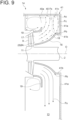
- FIG. 9 is a schematic cross-sectional view of an exhaust chamber of a steam turbine according to another embodiment of the present invention, taken along the axial direction, for describing a casing not having a first wall surface.
- a casing 40 is different from the casing 20 in that it does not have the first wall surface 21.
- the same features as those of the exhaust chamber 14 are denoted by the same reference signs, and description thereof will be omitted.
- the characteristic features of the casing 40 will be mainly described below.
- the casing 40 has a recess 41 provided along at least a part of the circumference on the radially outer side of the downstream end Pb of the bearing cone 16 and recessed downstream in the axial direction with respect to the downstream end Pb.
- the casing 40 further has an outer peripheral wall surface 40a positioned on the outer side of the bearing cone 16 and the flow guide 19 in the radial direction (up-down direction in FIG. 9 ) and extending along the axial direction (right-left direction in FIG. 9 ).
- the casing 40 may form at least a part of the outer casing 12 of the steam turbine 1, like the casing 20.
- the recess 41 guides the backflow Fc.
- the recess 41 has a second wall surface 41a (radial wall surface) positioned downstream of the downstream end Pb of the bearing cone 16 in the axial direction and extending along the radial direction and a third wall surface 41b (axial wall surface) connected at a first end to the radially inner end of the second wall surface 41a and extending in a direction intersecting the radial direction from the first end to a second end.
- a second wall surface 41a radial wall surface
- 41b axial wall surface
- the third wall surface 41b extends along the axial direction, in some embodiments, the third wall surface 41b may extend in a direction oblique to the axial direction, and the first end of the third wall surface 41b may be positioned on the radially outer side or inner side of the second end. Further, in the embodiment shown in FIG. 9 , the radially inner end of the recess 41, i.e., the second end of the third wall surface 41b is connected to the downstream end Pb of the bearing cone 16.
- the recess 41 is annularly formed. Further, the recess 41 further has a fourth wall surface 41c disposed along at least a part of the circumference.
- the fourth wall surface 41c is disposed opposite to the exhaust chamber outlet 13 through which the steam in the exhaust chamber 14 is discharged, and has a first end connected to the radially outer end of the second wall surface 41a and a second end connected to one end of the outer peripheral wall surface 40a of the casing 40.
- the long-dashed double-dotted line separates the outer peripheral wall surface 40a and the fourth wall surface 41c for convenience of description, the outer peripheral wall surface 40a and the fourth wall surface 41c may be integrally formed.
- the axial position of the second wall surface 41a in the embodiment shown in FIG. 9 may coincide with the wall surface (see FIG. 6 ) of the condenser 27. More specifically, for instance in the embodiments shown in FIGs. 2 and 4 , on the side with the exhaust chamber outlet 13, the second wall surface 23a is connected to the first end of the fourth wall surface 23c at the radially outer end. That is, the second wall surface 23a does not extend toward the exhaust chamber outlet 13 beyond the portion connected to the fourth wall surface 23c. Instead, the first wall surface 21 connected to the second end of the fourth wall surface 23c extend toward the exhaust chamber outlet 13 from the portion connected to the fourth wall surface 23c. By contrast, in the embodiment shown in FIG.
- the second wall surface 41a is not connected to the fourth wall surface 23c as shown in FIGs. 2 and 4 , but extends toward the exhaust chamber outlet 13. Further, the radially outer end of the second wall surface 41a is linearly connected and continuous with one end (radially inner end) of the wall surface of the condenser 27. The second wall surface 41a is flushed with the wall surface of the condenser 27 without forming a step therebetween.
- the recess 41 has the second wall surface 41a extending along the radial direction on the downstream side of the downstream end Pb of the bearing cone 16 with respect to the axial direction and the third wall surface 41b connected at the first end to the radially inner end of the second wall surface 41a and extending in a direction intersecting the radial direction from the first end to the second end. Since such a third wall surface 41b can guide the backflow Fc flowing upstream along the second wall surface 41a so as not to flow further upstream, it is possible to suppress separation of the steam at the bearing cone 16.
Landscapes
- Engineering & Computer Science (AREA)
- Mechanical Engineering (AREA)
- General Engineering & Computer Science (AREA)
- Chemical & Material Sciences (AREA)
- Combustion & Propulsion (AREA)
- Turbine Rotor Nozzle Sealing (AREA)
Claims (9)
- Chambre d'échappement (14) de turbine à vapeur comprenant :une enveloppe (20) ; etun cône de palier (16) disposé dans l'enveloppe de façon à recouvrir un palier (6),dans laquelle l'enveloppe présente un évidement (22) prévu le long d'au moins une partie d'une circonférence de l'enveloppe sur un côté radialement externe d'une extrémité aval du cône de palier et évidé en aval dans une direction axiale par rapport à l'extrémité aval du cône de palier, caractérisée en ce que l'évidement (22) comporte un premier évidement (23) ayant :une surface de paroi radiale (23a) positionnée en aval de l'extrémité aval du cône de palier dans la direction axiale et s'étendant le long d'une direction radiale ; etune surface de paroi axiale (23b) reliée au niveau d'une première extrémité à une extrémité radialement interne de la surface de paroi radiale (23a) et s'étendant dans une direction venant en intersection avec la direction radiale depuis la première extrémité jusqu'à une deuxième extrémité.
- Chambre d'échappement de turbine à vapeur selon la revendication 1,
dans laquelle la surface de paroi axiale (23b) est disposée le long de la direction axiale. - Chambre d'échappement de turbine à vapeur selon la revendication 1,
dans laquelle la première extrémité de la surface de paroi axiale (23b) est positionnée sur un côté interne de la deuxième extrémité de la surface de paroi axiale dans la direction radiale. - Chambre d'échappement (14) de turbine à vapeur comprenant :une enveloppe (20) ; etun cône de palier (16) disposé dans l'enveloppe de façon à recouvrir un palier (6),dans laquelle l'enveloppe présente un évidement (22) prévu le long d'au moins une partie d'une circonférence de l'enveloppe sur un côté radialement externe d'une extrémité aval du cône de palier et évidé en aval dans une direction axiale par rapport à l'extrémité aval du cône de palier,caractérisée en ce que l'évidement (22) comporte un deuxième évidement (24) ayant une surface de paroi incurvée (24a) incurvée et positionnée en aval de l'extrémité aval du cône de palier (16) dans la direction axiale.
- Chambre d'échappement de turbine à vapeur selon l'une quelconque des revendications 1 à 4,
dans laquelle l'évidement (22) est disposé à l'opposé d'une sortie de chambre d'échappement (13) par laquelle une vapeur dans la chambre d'échappement (14) de turbine à vapeur est évacuée. - Chambre d'échappement de turbine à vapeur selon l'une quelconque des revendications 1 à 5, comprenant en outre un premier guide (25) d'écoulement de circulation s'étendant vers l'extérieur dans la direction radiale à partir d'une portion périphérique interne de l'évidement (22).
- Chambre d'échappement de turbine à vapeur selon l'une quelconque des revendications 1 à 6, comprenant en outre un deuxième guide (26) d'écoulement de circulation s'étendant vers l'intérieur dans la direction radiale à partir d'une portion périphérique externe de l'évidement (22).
- Turbine à vapeur (1) comprenant :la chambre d'échappement (14) de turbine à vapeur selon l'une quelconque des revendications 1 à 7 ;une pale de rotor (8) disposée en amont de la chambre d'échappement de turbine à vapeur ; etune aube de stator (9) disposée en amont de la chambre d'échappement de turbine à vapeur.
- Turbine à vapeur selon la revendication 8, comprenant en outre un condenseur (27) pour la condensation d'une vapeur d'échappement évacuée de la chambre d'échappement (14) de turbine à vapeur,
dans laquelle une position de l'extrémité aval du cône de palier (16) dans la direction axiale coïncide avec une surface de paroi du condenseur.
Applications Claiming Priority (2)
| Application Number | Priority Date | Filing Date | Title |
|---|---|---|---|
| JP2017069366 | 2017-03-30 | ||
| PCT/JP2018/013530 WO2018181855A1 (fr) | 2017-03-30 | 2018-03-30 | Chambre d'échappement de turbine à vapeur et turbine à vapeur |
Publications (3)
| Publication Number | Publication Date |
|---|---|
| EP3604747A1 EP3604747A1 (fr) | 2020-02-05 |
| EP3604747A4 EP3604747A4 (fr) | 2020-12-09 |
| EP3604747B1 true EP3604747B1 (fr) | 2023-05-03 |
Family
ID=63677511
Family Applications (1)
| Application Number | Title | Priority Date | Filing Date |
|---|---|---|---|
| EP18776032.7A Active EP3604747B1 (fr) | 2017-03-30 | 2018-03-30 | Chambre d'échappement de turbine à vapeur et turbine à vapeur |
Country Status (6)
| Country | Link |
|---|---|
| US (1) | US11131217B2 (fr) |
| EP (1) | EP3604747B1 (fr) |
| JP (1) | JP6783924B2 (fr) |
| KR (1) | KR102400608B1 (fr) |
| CN (1) | CN110325714B (fr) |
| WO (1) | WO2018181855A1 (fr) |
Cited By (1)
| Publication number | Priority date | Publication date | Assignee | Title |
|---|---|---|---|---|
| DE112021003086B4 (de) | 2020-08-17 | 2025-02-06 | Mitsubishi Heavy Industries, Ltd. | Dampfturbinenabdampfkammer und Dampfturbine |
Families Citing this family (4)
| Publication number | Priority date | Publication date | Assignee | Title |
|---|---|---|---|---|
| JP7254472B2 (ja) * | 2018-09-28 | 2023-04-10 | 三菱重工業株式会社 | 蒸気タービンの排気室、蒸気タービン及び蒸気タービンの換装方法 |
| JP7184638B2 (ja) | 2018-12-28 | 2022-12-06 | 三菱重工業株式会社 | 蒸気タービン、及びその排気室 |
| JP7145775B2 (ja) * | 2019-01-31 | 2022-10-03 | 三菱重工業株式会社 | 回転機械 |
| CN119333250A (zh) * | 2024-12-06 | 2025-01-21 | 中国船舶集团有限公司第七0三研究所 | 一种船用汽轮机高压汽缸导流结构 |
Family Cites Families (14)
| Publication number | Priority date | Publication date | Assignee | Title |
|---|---|---|---|---|
| JPS5447908A (en) | 1977-09-26 | 1979-04-16 | Hitachi Ltd | Low pressure exhaust chamber |
| US5209634A (en) | 1991-02-20 | 1993-05-11 | Owczarek Jerzy A | Adjustable guide vane assembly for the exhaust flow passage of a steam turbine |
| US5257906A (en) * | 1992-06-30 | 1993-11-02 | Westinghouse Electric Corp. | Exhaust system for a turbomachine |
| JPH08260904A (ja) | 1995-03-29 | 1996-10-08 | Toshiba Corp | 蒸気タービン排気室 |
| JP3776580B2 (ja) | 1998-01-19 | 2006-05-17 | 三菱重工業株式会社 | 軸流タービンの排気装置 |
| US6261055B1 (en) * | 1999-08-03 | 2001-07-17 | Jerzy A. Owczarek | Exhaust flow diffuser for a steam turbine |
| US6419448B1 (en) * | 2000-03-20 | 2002-07-16 | Jerzy A. Owczarek | Flow by-pass system for use in steam turbine exhaust hoods |
| JP2003027905A (ja) | 2001-07-16 | 2003-01-29 | Mitsubishi Heavy Ind Ltd | 軸流タービンの排気装置 |
| JP4541813B2 (ja) | 2004-09-17 | 2010-09-08 | 株式会社日立製作所 | 蒸気タービン低圧排気室 |
| JP4627217B2 (ja) | 2005-05-30 | 2011-02-09 | 株式会社日立製作所 | タービン排気装置 |
| JP4664854B2 (ja) | 2006-04-20 | 2011-04-06 | 株式会社東芝 | 低圧蒸気タービン |
| JP5422470B2 (ja) | 2010-04-05 | 2014-02-19 | 株式会社東芝 | 軸流タービン |
| JP5499348B2 (ja) * | 2011-01-14 | 2014-05-21 | 株式会社日立製作所 | 蒸気タービンの排気装置 |
| JP2019157680A (ja) * | 2018-03-09 | 2019-09-19 | 三菱重工業株式会社 | 蒸気タービン装置 |
-
2018
- 2018-03-30 EP EP18776032.7A patent/EP3604747B1/fr active Active
- 2018-03-30 KR KR1020197027131A patent/KR102400608B1/ko active Active
- 2018-03-30 CN CN201880014172.0A patent/CN110325714B/zh active Active
- 2018-03-30 JP JP2019510216A patent/JP6783924B2/ja active Active
- 2018-03-30 US US16/493,143 patent/US11131217B2/en active Active
- 2018-03-30 WO PCT/JP2018/013530 patent/WO2018181855A1/fr not_active Ceased
Cited By (2)
| Publication number | Priority date | Publication date | Assignee | Title |
|---|---|---|---|---|
| DE112021003086B4 (de) | 2020-08-17 | 2025-02-06 | Mitsubishi Heavy Industries, Ltd. | Dampfturbinenabdampfkammer und Dampfturbine |
| US12276203B2 (en) | 2020-08-17 | 2025-04-15 | Mitsubishi Heavy Industries, Ltd. | Steam turbine exhaust chamber and steam turbine |
Also Published As
| Publication number | Publication date |
|---|---|
| KR102400608B1 (ko) | 2022-05-23 |
| KR20190116451A (ko) | 2019-10-14 |
| JPWO2018181855A1 (ja) | 2019-12-19 |
| US11131217B2 (en) | 2021-09-28 |
| CN110325714A (zh) | 2019-10-11 |
| EP3604747A4 (fr) | 2020-12-09 |
| JP6783924B2 (ja) | 2020-11-11 |
| CN110325714B (zh) | 2022-06-24 |
| EP3604747A1 (fr) | 2020-02-05 |
| US20200011206A1 (en) | 2020-01-09 |
| WO2018181855A1 (fr) | 2018-10-04 |
Similar Documents
| Publication | Publication Date | Title |
|---|---|---|
| US11131217B2 (en) | Steam turbine exhaust chamber and steam turbine | |
| US11149588B2 (en) | Exhaust chamber of steam turbine, flow guide for steam turbine exhaust chamber, and steam turbine | |
| EP3018297B1 (fr) | Dispositif d'étanchéité et machine turbo | |
| EP2476868B1 (fr) | Système d'échappement pour turbine à vapeur | |
| US9359900B2 (en) | Exhaust diffuser | |
| JP5535562B2 (ja) | 排出スクロール及びターボ機械 | |
| EP2617961A1 (fr) | Structure de spirale de turbine | |
| CN104520540B (zh) | 轴流式流体机械 | |
| KR101720449B1 (ko) | 축류 회전 기계 및 디퓨저 | |
| EP3196437A1 (fr) | Turbomachine | |
| EP2578810A1 (fr) | Structure de joint, machine à turbine équipée de cette structure et centrale électrique équipée de ladite machine à turbine | |
| US20190277139A1 (en) | Steam turbine apparatus | |
| JP6847673B2 (ja) | タービン排気室 | |
| EP2226471B1 (fr) | Dérivation de fluide moteur pour turbine axiale | |
| US20180306365A1 (en) | Bend pipe and fluid machine comprising same | |
| US20130081731A1 (en) | Exhaust gas diffuser | |
| EP3705697A1 (fr) | Turbine et turbocompresseur | |
| CN106256994B (zh) | 轴流涡轮机 | |
| JP6689105B2 (ja) | 多段軸流圧縮機及びガスタービン | |
| JP4146371B2 (ja) | 遠心圧縮機 | |
| JP6209787B2 (ja) | シール構造及び回転機械 | |
| US20210148249A1 (en) | Steam turbine | |
| JP6994976B2 (ja) | タービンの排気室及びタービン | |
| US12276203B2 (en) | Steam turbine exhaust chamber and steam turbine | |
| CN105723096A (zh) | 叶轮及离心压缩机 |
Legal Events
| Date | Code | Title | Description |
|---|---|---|---|
| STAA | Information on the status of an ep patent application or granted ep patent |
Free format text: STATUS: THE INTERNATIONAL PUBLICATION HAS BEEN MADE |
|
| PUAI | Public reference made under article 153(3) epc to a published international application that has entered the european phase |
Free format text: ORIGINAL CODE: 0009012 |
|
| STAA | Information on the status of an ep patent application or granted ep patent |
Free format text: STATUS: REQUEST FOR EXAMINATION WAS MADE |
|
| 17P | Request for examination filed |
Effective date: 20190917 |
|
| AK | Designated contracting states |
Kind code of ref document: A1 Designated state(s): AL AT BE BG CH CY CZ DE DK EE ES FI FR GB GR HR HU IE IS IT LI LT LU LV MC MK MT NL NO PL PT RO RS SE SI SK SM TR |
|
| AX | Request for extension of the european patent |
Extension state: BA ME |
|
| DAV | Request for validation of the european patent (deleted) | ||
| DAX | Request for extension of the european patent (deleted) | ||
| A4 | Supplementary search report drawn up and despatched |
Effective date: 20201110 |
|
| RIC1 | Information provided on ipc code assigned before grant |
Ipc: F01D 25/30 20060101AFI20201104BHEP |
|
| RAP1 | Party data changed (applicant data changed or rights of an application transferred) |
Owner name: MITSUBISHI POWER, LTD. |
|
| RAP1 | Party data changed (applicant data changed or rights of an application transferred) |
Owner name: MITSUBISHI HEAVY INDUSTRIES, LTD. |
|
| GRAP | Despatch of communication of intention to grant a patent |
Free format text: ORIGINAL CODE: EPIDOSNIGR1 |
|
| STAA | Information on the status of an ep patent application or granted ep patent |
Free format text: STATUS: GRANT OF PATENT IS INTENDED |
|
| INTG | Intention to grant announced |
Effective date: 20221220 |
|
| GRAJ | Information related to disapproval of communication of intention to grant by the applicant or resumption of examination proceedings by the epo deleted |
Free format text: ORIGINAL CODE: EPIDOSDIGR1 |
|
| STAA | Information on the status of an ep patent application or granted ep patent |
Free format text: STATUS: REQUEST FOR EXAMINATION WAS MADE |
|
| GRAP | Despatch of communication of intention to grant a patent |
Free format text: ORIGINAL CODE: EPIDOSNIGR1 |
|
| STAA | Information on the status of an ep patent application or granted ep patent |
Free format text: STATUS: GRANT OF PATENT IS INTENDED |
|
| INTC | Intention to grant announced (deleted) | ||
| INTG | Intention to grant announced |
Effective date: 20230215 |
|
| GRAS | Grant fee paid |
Free format text: ORIGINAL CODE: EPIDOSNIGR3 |
|
| GRAA | (expected) grant |
Free format text: ORIGINAL CODE: 0009210 |
|
| STAA | Information on the status of an ep patent application or granted ep patent |
Free format text: STATUS: THE PATENT HAS BEEN GRANTED |
|
| AK | Designated contracting states |
Kind code of ref document: B1 Designated state(s): AL AT BE BG CH CY CZ DE DK EE ES FI FR GB GR HR HU IE IS IT LI LT LU LV MC MK MT NL NO PL PT RO RS SE SI SK SM TR |
|
| REG | Reference to a national code |
Ref country code: GB Ref legal event code: FG4D |
|
| REG | Reference to a national code |
Ref country code: AT Ref legal event code: REF Ref document number: 1564762 Country of ref document: AT Kind code of ref document: T Effective date: 20230515 Ref country code: CH Ref legal event code: EP |
|
| REG | Reference to a national code |
Ref country code: DE Ref legal event code: R096 Ref document number: 602018049275 Country of ref document: DE |
|
| REG | Reference to a national code |
Ref country code: IE Ref legal event code: FG4D |
|
| REG | Reference to a national code |
Ref country code: LT Ref legal event code: MG9D |
|
| REG | Reference to a national code |
Ref country code: NL Ref legal event code: MP Effective date: 20230503 |
|
| REG | Reference to a national code |
Ref country code: AT Ref legal event code: MK05 Ref document number: 1564762 Country of ref document: AT Kind code of ref document: T Effective date: 20230503 |
|
| PG25 | Lapsed in a contracting state [announced via postgrant information from national office to epo] |
Ref country code: SE Free format text: LAPSE BECAUSE OF FAILURE TO SUBMIT A TRANSLATION OF THE DESCRIPTION OR TO PAY THE FEE WITHIN THE PRESCRIBED TIME-LIMIT Effective date: 20230503 Ref country code: PT Free format text: LAPSE BECAUSE OF FAILURE TO SUBMIT A TRANSLATION OF THE DESCRIPTION OR TO PAY THE FEE WITHIN THE PRESCRIBED TIME-LIMIT Effective date: 20230904 Ref country code: NO Free format text: LAPSE BECAUSE OF FAILURE TO SUBMIT A TRANSLATION OF THE DESCRIPTION OR TO PAY THE FEE WITHIN THE PRESCRIBED TIME-LIMIT Effective date: 20230803 Ref country code: NL Free format text: LAPSE BECAUSE OF FAILURE TO SUBMIT A TRANSLATION OF THE DESCRIPTION OR TO PAY THE FEE WITHIN THE PRESCRIBED TIME-LIMIT Effective date: 20230503 Ref country code: ES Free format text: LAPSE BECAUSE OF FAILURE TO SUBMIT A TRANSLATION OF THE DESCRIPTION OR TO PAY THE FEE WITHIN THE PRESCRIBED TIME-LIMIT Effective date: 20230503 Ref country code: AT Free format text: LAPSE BECAUSE OF FAILURE TO SUBMIT A TRANSLATION OF THE DESCRIPTION OR TO PAY THE FEE WITHIN THE PRESCRIBED TIME-LIMIT Effective date: 20230503 |
|
| PG25 | Lapsed in a contracting state [announced via postgrant information from national office to epo] |
Ref country code: RS Free format text: LAPSE BECAUSE OF FAILURE TO SUBMIT A TRANSLATION OF THE DESCRIPTION OR TO PAY THE FEE WITHIN THE PRESCRIBED TIME-LIMIT Effective date: 20230503 Ref country code: PL Free format text: LAPSE BECAUSE OF FAILURE TO SUBMIT A TRANSLATION OF THE DESCRIPTION OR TO PAY THE FEE WITHIN THE PRESCRIBED TIME-LIMIT Effective date: 20230503 Ref country code: LV Free format text: LAPSE BECAUSE OF FAILURE TO SUBMIT A TRANSLATION OF THE DESCRIPTION OR TO PAY THE FEE WITHIN THE PRESCRIBED TIME-LIMIT Effective date: 20230503 Ref country code: LT Free format text: LAPSE BECAUSE OF FAILURE TO SUBMIT A TRANSLATION OF THE DESCRIPTION OR TO PAY THE FEE WITHIN THE PRESCRIBED TIME-LIMIT Effective date: 20230503 Ref country code: IS Free format text: LAPSE BECAUSE OF FAILURE TO SUBMIT A TRANSLATION OF THE DESCRIPTION OR TO PAY THE FEE WITHIN THE PRESCRIBED TIME-LIMIT Effective date: 20230903 Ref country code: HR Free format text: LAPSE BECAUSE OF FAILURE TO SUBMIT A TRANSLATION OF THE DESCRIPTION OR TO PAY THE FEE WITHIN THE PRESCRIBED TIME-LIMIT Effective date: 20230503 Ref country code: GR Free format text: LAPSE BECAUSE OF FAILURE TO SUBMIT A TRANSLATION OF THE DESCRIPTION OR TO PAY THE FEE WITHIN THE PRESCRIBED TIME-LIMIT Effective date: 20230804 |
|
| PG25 | Lapsed in a contracting state [announced via postgrant information from national office to epo] |
Ref country code: FI Free format text: LAPSE BECAUSE OF FAILURE TO SUBMIT A TRANSLATION OF THE DESCRIPTION OR TO PAY THE FEE WITHIN THE PRESCRIBED TIME-LIMIT Effective date: 20230503 |
|
| PG25 | Lapsed in a contracting state [announced via postgrant information from national office to epo] |
Ref country code: SK Free format text: LAPSE BECAUSE OF FAILURE TO SUBMIT A TRANSLATION OF THE DESCRIPTION OR TO PAY THE FEE WITHIN THE PRESCRIBED TIME-LIMIT Effective date: 20230503 |
|
| PG25 | Lapsed in a contracting state [announced via postgrant information from national office to epo] |
Ref country code: SM Free format text: LAPSE BECAUSE OF FAILURE TO SUBMIT A TRANSLATION OF THE DESCRIPTION OR TO PAY THE FEE WITHIN THE PRESCRIBED TIME-LIMIT Effective date: 20230503 Ref country code: SK Free format text: LAPSE BECAUSE OF FAILURE TO SUBMIT A TRANSLATION OF THE DESCRIPTION OR TO PAY THE FEE WITHIN THE PRESCRIBED TIME-LIMIT Effective date: 20230503 Ref country code: RO Free format text: LAPSE BECAUSE OF FAILURE TO SUBMIT A TRANSLATION OF THE DESCRIPTION OR TO PAY THE FEE WITHIN THE PRESCRIBED TIME-LIMIT Effective date: 20230503 Ref country code: EE Free format text: LAPSE BECAUSE OF FAILURE TO SUBMIT A TRANSLATION OF THE DESCRIPTION OR TO PAY THE FEE WITHIN THE PRESCRIBED TIME-LIMIT Effective date: 20230503 Ref country code: DK Free format text: LAPSE BECAUSE OF FAILURE TO SUBMIT A TRANSLATION OF THE DESCRIPTION OR TO PAY THE FEE WITHIN THE PRESCRIBED TIME-LIMIT Effective date: 20230503 Ref country code: CZ Free format text: LAPSE BECAUSE OF FAILURE TO SUBMIT A TRANSLATION OF THE DESCRIPTION OR TO PAY THE FEE WITHIN THE PRESCRIBED TIME-LIMIT Effective date: 20230503 |
|
| REG | Reference to a national code |
Ref country code: DE Ref legal event code: R097 Ref document number: 602018049275 Country of ref document: DE |
|
| PLBE | No opposition filed within time limit |
Free format text: ORIGINAL CODE: 0009261 |
|
| STAA | Information on the status of an ep patent application or granted ep patent |
Free format text: STATUS: NO OPPOSITION FILED WITHIN TIME LIMIT |
|
| 26N | No opposition filed |
Effective date: 20240206 |
|
| PG25 | Lapsed in a contracting state [announced via postgrant information from national office to epo] |
Ref country code: SI Free format text: LAPSE BECAUSE OF FAILURE TO SUBMIT A TRANSLATION OF THE DESCRIPTION OR TO PAY THE FEE WITHIN THE PRESCRIBED TIME-LIMIT Effective date: 20230503 |
|
| PG25 | Lapsed in a contracting state [announced via postgrant information from national office to epo] |
Ref country code: SI Free format text: LAPSE BECAUSE OF FAILURE TO SUBMIT A TRANSLATION OF THE DESCRIPTION OR TO PAY THE FEE WITHIN THE PRESCRIBED TIME-LIMIT Effective date: 20230503 Ref country code: IT Free format text: LAPSE BECAUSE OF FAILURE TO SUBMIT A TRANSLATION OF THE DESCRIPTION OR TO PAY THE FEE WITHIN THE PRESCRIBED TIME-LIMIT Effective date: 20230503 |
|
| REG | Reference to a national code |
Ref country code: CH Ref legal event code: PL |
|
| PG25 | Lapsed in a contracting state [announced via postgrant information from national office to epo] |
Ref country code: BG Free format text: LAPSE BECAUSE OF FAILURE TO SUBMIT A TRANSLATION OF THE DESCRIPTION OR TO PAY THE FEE WITHIN THE PRESCRIBED TIME-LIMIT Effective date: 20230503 |
|
| PG25 | Lapsed in a contracting state [announced via postgrant information from national office to epo] |
Ref country code: LU Free format text: LAPSE BECAUSE OF NON-PAYMENT OF DUE FEES Effective date: 20240330 |
|
| PG25 | Lapsed in a contracting state [announced via postgrant information from national office to epo] |
Ref country code: MC Free format text: LAPSE BECAUSE OF FAILURE TO SUBMIT A TRANSLATION OF THE DESCRIPTION OR TO PAY THE FEE WITHIN THE PRESCRIBED TIME-LIMIT Effective date: 20230503 |
|
| GBPC | Gb: european patent ceased through non-payment of renewal fee |
Effective date: 20240330 |
|
| PG25 | Lapsed in a contracting state [announced via postgrant information from national office to epo] |
Ref country code: MC Free format text: LAPSE BECAUSE OF FAILURE TO SUBMIT A TRANSLATION OF THE DESCRIPTION OR TO PAY THE FEE WITHIN THE PRESCRIBED TIME-LIMIT Effective date: 20230503 Ref country code: LU Free format text: LAPSE BECAUSE OF NON-PAYMENT OF DUE FEES Effective date: 20240330 Ref country code: BG Free format text: LAPSE BECAUSE OF FAILURE TO SUBMIT A TRANSLATION OF THE DESCRIPTION OR TO PAY THE FEE WITHIN THE PRESCRIBED TIME-LIMIT Effective date: 20230503 |
|
| REG | Reference to a national code |
Ref country code: BE Ref legal event code: MM Effective date: 20240331 |
|
| PG25 | Lapsed in a contracting state [announced via postgrant information from national office to epo] |
Ref country code: BE Free format text: LAPSE BECAUSE OF NON-PAYMENT OF DUE FEES Effective date: 20240331 |
|
| PG25 | Lapsed in a contracting state [announced via postgrant information from national office to epo] |
Ref country code: GB Free format text: LAPSE BECAUSE OF NON-PAYMENT OF DUE FEES Effective date: 20240330 |
|
| PG25 | Lapsed in a contracting state [announced via postgrant information from national office to epo] |
Ref country code: IE Free format text: LAPSE BECAUSE OF NON-PAYMENT OF DUE FEES Effective date: 20240330 |
|
| PG25 | Lapsed in a contracting state [announced via postgrant information from national office to epo] |
Ref country code: IE Free format text: LAPSE BECAUSE OF NON-PAYMENT OF DUE FEES Effective date: 20240330 Ref country code: GB Free format text: LAPSE BECAUSE OF NON-PAYMENT OF DUE FEES Effective date: 20240330 Ref country code: BE Free format text: LAPSE BECAUSE OF NON-PAYMENT OF DUE FEES Effective date: 20240331 Ref country code: CH Free format text: LAPSE BECAUSE OF NON-PAYMENT OF DUE FEES Effective date: 20240331 |
|
| PG25 | Lapsed in a contracting state [announced via postgrant information from national office to epo] |
Ref country code: CY Free format text: LAPSE BECAUSE OF FAILURE TO SUBMIT A TRANSLATION OF THE DESCRIPTION OR TO PAY THE FEE WITHIN THE PRESCRIBED TIME-LIMIT; INVALID AB INITIO Effective date: 20180330 |
|
| PG25 | Lapsed in a contracting state [announced via postgrant information from national office to epo] |
Ref country code: HU Free format text: LAPSE BECAUSE OF FAILURE TO SUBMIT A TRANSLATION OF THE DESCRIPTION OR TO PAY THE FEE WITHIN THE PRESCRIBED TIME-LIMIT; INVALID AB INITIO Effective date: 20180330 |
|
| PG25 | Lapsed in a contracting state [announced via postgrant information from national office to epo] |
Ref country code: TR Free format text: LAPSE BECAUSE OF FAILURE TO SUBMIT A TRANSLATION OF THE DESCRIPTION OR TO PAY THE FEE WITHIN THE PRESCRIBED TIME-LIMIT Effective date: 20230503 |
|
| PGFP | Annual fee paid to national office [announced via postgrant information from national office to epo] |
Ref country code: DE Payment date: 20260204 Year of fee payment: 9 |
|
| PGFP | Annual fee paid to national office [announced via postgrant information from national office to epo] |
Ref country code: FR Payment date: 20260209 Year of fee payment: 9 |