EP3604831A1 - Verbundabdichtungs-dübel - Google Patents
Verbundabdichtungs-dübel Download PDFInfo
- Publication number
- EP3604831A1 EP3604831A1 EP19185074.2A EP19185074A EP3604831A1 EP 3604831 A1 EP3604831 A1 EP 3604831A1 EP 19185074 A EP19185074 A EP 19185074A EP 3604831 A1 EP3604831 A1 EP 3604831A1
- Authority
- EP
- European Patent Office
- Prior art keywords
- base body
- axial direction
- section
- composite sealing
- sealant
- Prior art date
- Legal status (The legal status is an assumption and is not a legal conclusion. Google has not performed a legal analysis and makes no representation as to the accuracy of the status listed.)
- Granted
Links
Images



Classifications
-
- F—MECHANICAL ENGINEERING; LIGHTING; HEATING; WEAPONS; BLASTING
- F16—ENGINEERING ELEMENTS AND UNITS; GENERAL MEASURES FOR PRODUCING AND MAINTAINING EFFECTIVE FUNCTIONING OF MACHINES OR INSTALLATIONS; THERMAL INSULATION IN GENERAL
- F16B—DEVICES FOR FASTENING OR SECURING CONSTRUCTIONAL ELEMENTS OR MACHINE PARTS TOGETHER, e.g. NAILS, BOLTS, CIRCLIPS, CLAMPS, CLIPS OR WEDGES; JOINTS OR JOINTING
- F16B13/00—Dowels or other devices fastened in walls or the like by inserting them in holes made therein for that purpose
- F16B13/02—Dowels or other devices fastened in walls or the like by inserting them in holes made therein for that purpose in one piece with protrusions or ridges on the shaft
-
- F—MECHANICAL ENGINEERING; LIGHTING; HEATING; WEAPONS; BLASTING
- F16—ENGINEERING ELEMENTS AND UNITS; GENERAL MEASURES FOR PRODUCING AND MAINTAINING EFFECTIVE FUNCTIONING OF MACHINES OR INSTALLATIONS; THERMAL INSULATION IN GENERAL
- F16B—DEVICES FOR FASTENING OR SECURING CONSTRUCTIONAL ELEMENTS OR MACHINE PARTS TOGETHER, e.g. NAILS, BOLTS, CIRCLIPS, CLAMPS, CLIPS OR WEDGES; JOINTS OR JOINTING
- F16B13/00—Dowels or other devices fastened in walls or the like by inserting them in holes made therein for that purpose
- F16B13/12—Separate metal or non-separate or non-metal dowel sleeves fastened by inserting the screw, nail or the like
- F16B13/124—Separate metal or non-separate or non-metal dowel sleeves fastened by inserting the screw, nail or the like fastened by inserting a threaded element, e.g. screw or bolt
-
- F—MECHANICAL ENGINEERING; LIGHTING; HEATING; WEAPONS; BLASTING
- F16—ENGINEERING ELEMENTS AND UNITS; GENERAL MEASURES FOR PRODUCING AND MAINTAINING EFFECTIVE FUNCTIONING OF MACHINES OR INSTALLATIONS; THERMAL INSULATION IN GENERAL
- F16B—DEVICES FOR FASTENING OR SECURING CONSTRUCTIONAL ELEMENTS OR MACHINE PARTS TOGETHER, e.g. NAILS, BOLTS, CIRCLIPS, CLAMPS, CLIPS OR WEDGES; JOINTS OR JOINTING
- F16B13/00—Dowels or other devices fastened in walls or the like by inserting them in holes made therein for that purpose
- F16B2013/006—Dowels or other devices fastened in walls or the like by inserting them in holes made therein for that purpose with sealing means
Definitions
- a composite sealing dowel is understood to mean a screw dowel which develops a sealing effect between a screw and a structure in which the screw dowel is arranged, in particular with regard to moisture and liquids.
- the screw dowel penetrates a composite seal provided in the structure and seals reliably and permanently against this composite seal.
- Composite sealing systems with a protective layer of ceramic covering and clothing building materials or natural or cast stone tiles are often used for this. These usually consist of a ceramic tile or plate, grout between the tiles or plates, tile adhesive under the tile or plate and a seal.
- the seal is usually arranged between the tile adhesive and a building structure (a wall or a floor, for example made of brick or concrete) and glued to the building structure.
- powdery, pasty, liquid or sheet-like sealing materials are used for the sealing.
- Suitable liquid waterproofing materials can be obtained from Sopro Bauchemie GmbH, Wiesbaden, Germany, in various configurations, for example under the designations Surface Seal Flexible (FDF), Seal Slurry Flex (DSF), Turbo Seal Slurry (TDS) or PU Surface Seal (PU-FD).
- Suitable sheet-like sealing materials can be in various configurations, for example under the name sealing and decoupling sheet AEB (protected trademark) or sealing and decoupling membrane plus (protected trademark), can be obtained from Sopro Bauchemie GmbH, Wiesbaden, Germany.
- Such sheet-like sealing materials consist, for example, of tear-resistant polypropylene film with a special fleece fabric coating on both sides made of polypropylene and a thickness of approximately 0.3 mm to 0.9 mm.
- a particular problem in the case of composite waterproofing systems is the penetration subsequently introduced, in particular boreholes, since these typically penetrate the composite waterproofing right down to the building structure. Even with such penetrations, the tightness of the composite sealing system must be guaranteed.
- a composite sealing dowel with a hollow cylindrical base body
- the hollow cylindrical base body need not be a perfect hollow cylinder in the mathematical sense.
- the hollow cylinder can be closed on one side and rounded at the closed end. It is also permissible for an outer surface of the hollow cylinder to have penetrations, depressions or projections. It points the base body has an opening for receiving a screw in the axial direction at a first end.
- the composite sealing dowel expands.
- the screw is secured against being pulled out by a frictional connection between the composite sealing dowel and the surrounding material.
- the screw forms a counter thread in the inner part of the composite sealing dowel, plastically deforming the material from which the composite sealing dowel is formed and additionally displacing it radially outward, thus spreading the composite sealing dowel.
- the base body has a first section and a second section in the axial direction, the first section being arranged between the second section and the first end of the base body.
- the base body On its radially outer lateral surface, the base body has an elastic sealant in the first section.
- the base body on its radially outer lateral surface is free of the elastic sealant.
- the elastic sealant is formed from a material that differs from the material from which the base body is formed.
- the first and second sections are determined by the presence or absence of elastic sealant.
- a composite seal which, as described above, consists of a protective layer made of a ceramic tile or plate or a natural or concrete stone, grout between the tiles or plates, tile adhesive located under the tile or plate and a seal the elastic sealant present in the first section brings about a sealing effect which, in the axial direction of the composite sealing dowel, comprises the seal of the composite seal and sections on both sides of the seal and thus acts across layers.
- the material forming the base body has in the first section on the radially outer lateral surface of the base body a recess which extends in the axial and radial directions and in which the elastic sealant is fully or partially inserted. Since a recess is set back radially inward relative to the adjacent radially outer lateral surface of the base body, it is possible to fix the position of the elastic sealant in the axial direction of the base body by fully or partially inserting the elastic sealant. This also makes it possible to ensure that a radially outer lateral surface of the elastic sealant is flush with the radially outer lateral surface of the base body (which means that both surfaces are flush) or protrudes only slightly in relation to this.
- “Slightly” should be understood to mean that the radially outer lateral surface of the elastic sealant projects over the radially outer lateral surface of the base body by less than the average wall thickness of the base body and in particular by less than half the average wall thickness of the base body. According to one embodiment, the radially outer lateral surface of the elastic sealant projects from the radially outer lateral surface of the base body by less than 1 mm and in particular by less than 0.5 mm.
- the term "inserted” is intended to include both the subsequent insertion of a separate elastic sealant in the form of a ring and the encapsulation of the base body with the elastic sealant.
- the average thickness of the outer wall of the base body is the radial distance between one and a radially outer one
- the circumferential surface of the base body defines the smallest circle to form the largest circle defined by a radially inner circumferential surface of the base body, the centers of both circles coinciding.
- the recess extends in the axial direction over the entire first section of the base body, which means that the elastic sealant is inserted into the recess in the base body over its entire axial extent.
- the recess extends in the axial direction over between 20% and 90% or over between 40% and 85% or over between 60% and 80% of the first section of the base body, which means that the elastic sealant is based on it axial extension is only partially inserted into the recess in the base body.
- the recess extends completely around the base body in the circumferential direction; then the elastic sealant used is ring-shaped in and of itself.
- a depth of the recess in the first section in the radial direction is between 0.25 mm and 2.5 mm or between 0.5 mm and 2.25 mm or between 1.0 mm and 2.0 mm.
- a recess with such a depth ensures that sufficient elastic sealant can be arranged around the base body in order to achieve the intended sealing effect.
- the base body has in the first section on its radially inner lateral surface a projection which extends in the radial and axial directions.
- the projection extends in the axial direction over the entire first section of the base body, and is subsequently arranged in the axial direction at the same position as the elastic sealant.
- the projection extends in the axial direction over between 25% and 95% or over between 45% and 90% or over between 65% and 85% of the first section of the base body.
- the projection can either have a smaller extent in the axial direction of the base body than the elastic sealant and lie completely in the first section or can also be offset in the axial direction with respect to the first section. If the projection is offset in the axial direction with respect to the first section, the projection can even be larger than the first section.
- the projection extends around the circumference completely within the base body.
- a plurality of projections separated from one another are provided distributed in the circumferential direction. The use of a plurality of projections distributed in the circumferential direction avoids excessive wall thicknesses of the base body.
- a height of the projection in the radial direction with respect to the radially inner lateral surface of the base body is between 0.25 mm and 2.5 mm or between 0.5 mm and 2.25 mm or between 1.0 mm and 2.0 mm , According to one embodiment, the height of the projection in the radial direction is less than or equal to the thickness of the elastic sealant in the radial direction.
- the base body in the first section likewise has an elastic sealant on its radially inner lateral surface.
- the base body also has an elastic sealant in its interior, the sealing effect is improved compared to a screw screwed into the composite sealing dowel.
- the elastic sealant arranged in the first section on the radially inner lateral surface extends in the axial direction over the entire first section of the base body.
- the elastic sealant completely surrounds the base body on its radially outer lateral surface and / or on its radially inner lateral surface in the circumferential direction of the base body, and thus forms a ring.
- the elastic sealant is an elastomer body which completely surrounds the base body on its radially outer lateral surface and / or on its radially inner lateral surface in the circumferential direction of the base body, and thus forms a ring.
- the elastomer body is a type of rubber, perfluorinated rubber (FFKM or FFPM), polyethylene (PE) or polytetrafluoroethylene (PTFE).
- the hollow cylindrical base body of the composite sealing dowel has a pasty sealant with the opening for the screw in its interior. Since the base body of composite sealing anchors typically does not consist of pasty material, the sealant is thus formed from a material which differs from the material from which the base body is formed. Furthermore, an outer wall of the base body has several openings and / or weakenings.
- a “weakening” is understood to mean an area in which the outer wall has a thickness of at least 50% and in particular at least 75% and further is in particular reduced by at least 90% compared to the average thickness of the outer wall at this point.
- the pasty sealant pressed outward of the base body produces a sealing effect which, in the axial direction of the composite sealing dowel, comprises the composite seal and sections on both sides of the composite seal and thus acts across layers.
- pasty sealant remaining in the interior of the base body provides a good seal against a screw screwed into the composite sealing dowel.
- the composite sealing dowel outside of the base body is free of pasty sealant.
- the pasty sealant is provided in a first end in the axial direction of the hollow cylindrical base body with the opening for the screw.
- the hollow cylindrical base body is completely or at least 2/3 or at least half or at least one third filled with the pasty sealant in the axial direction.
- the openings and / or weakenings are spaced apart from one another in the circumferential direction.
- the openings and / or weakenings are arranged distributed uniformly around the basic body in the circumferential direction.
- the openings are elongated holes, the longitudinal axes of which are oriented in the axial direction of the base body or enclose an angle of between 5 ° and 60 ° with the axial direction of the base body or enclose an angle of between 5 ° and 30 ° with the axial direction of the base body.
- the weakenings are long grooves, the longitudinal axes of which are oriented in the axial direction of the base body or enclose an angle of between 5 ° and 60 ° with the axial direction of the base body or enclose an angle of between 5 ° and 30 ° with the axial direction of the base body. Due to the largely axial orientation of the openings / weakenings, a reduction in the tensile force that can be absorbed in the axial direction by the composite sealing dowel is kept low.
- the base body has a first partition, which is arranged between the pasty sealant and the first end of the base body and closes off the pasty sealant with respect to the opening of the base body. In this way, drying out or hardening of the pasty sealant can be avoided.
- the first partition is formed in one piece with the base body.
- the first partition is pressed or glued or welded or inserted into the base body. It is emphasized that the partition also has the shape of a plug and can be designed such that it can be removed from the base body.
- the base body has a second partition, which is spaced apart from the first partition in the axial direction.
- the pasty sealant can then be arranged between the first partition and the second partition.
- the two partitions serve to limit the Section in which the pasty sealant is present.
- the second partition is formed in one piece with the base body.
- the second partition is pressed or glued or welded or inserted into the base body.
- a thickness of the (first and / or second) partition is reduced by at least 50% or by at least 75% or by at least 90% compared to an average thickness of the outer wall of the base body. This ensures that the (first and / or second) partition can easily be penetrated by a screw. According to one embodiment, the thickness of the second partition is greater than or equal to the thickness of the first partition.
- the pasty sealant is a butyl rubber sealant or a polysulfide sealant or a silicone sealant or a polyurethane sealant or an MS polymer sealant or a resin.
- Such materials are safe to process, can be easily combined with composite sealing systems and have good and long-lasting sealing properties.
- the base body has a section in the axial direction in which the base body is free of sealant, this section adjoining the first end of the base body and extending from the first end by between 1 mm and 10 mm or by between 2. 5 mm and 8 mm or extends between 3 mm and 6 mm in the axial direction. In this way it is avoided that the sealant penetrates outside of a penetration into which the composite sealing dowel is inserted.
- the section of the base body in which the base body has sealant extends over between 5 mm and 30 mm or over between 7 mm and 20 mm or over between 10 mm and 15 mm in the axial direction.
- the section of the base body in which the base body has sealant extends in the axial direction over between 20% and 70% of the total length of the base body or over between 30% and 60% of the total length of the base body or over between 40% and 50 % of the total length of the body.
- the composite sealing dowel is well adapted for sealing penetrations made in composite sealing systems, since such an axial extension of the sealant can act across layers by placing the composite sealing plug in the axial direction of the seal of the composite seal and on both sides of the sealant sealant is arranged.
- the base body is formed from plastic and in particular from polyamide or metal.
- a composite sealing dowel has a hollow cylindrical base body with an opening arranged at an end in the axial direction for receiving a screw.
- the base body in each case has on its radially inner and radially outer outer surfaces elastomer layers, which are continuous in both the axial direction and in the circumferential direction of the composite sealing dowel.
- This can also be a single common elastomer layer; the base body can thus be formed entirely from elastomer.
- the extent of the hollow cylindrical base body in the axial direction is at least 10 mm or at least 15 mm.
- the composite sealing dowel Due to its elastomer layers, the composite sealing dowel has good sealing properties both against an inner wall of the penetration and against a screw inserted through the opening in the base body. If the penetration is enforced by a composite seal, which, as described above, can be formed from a ceramic tile or plate, joint mortar between the tiles or plates, tile adhesive under the tile or plate and a seal, this causes the elastomer layer on the radially outer outer surface a sealing effect which in the axial direction of the composite sealing dowel comprises the sealing of the composite sealing and sections on both sides of the sealing and thus acts across layers.
- a composite seal which, as described above, can be formed from a ceramic tile or plate, joint mortar between the tiles or plates, tile adhesive under the tile or plate and a seal, this causes the elastomer layer on the radially outer outer surface a sealing effect which in the axial direction of the composite sealing dowel comprises the sealing of the composite sealing and sections on both sides of the sealing and thus acts across layers.
- the base body has a layer of polyamide or metal between its radially inner and radially outer elastomer layers.
- a core considerably increases the stability of the composite sealing dowel and thus facilitates insertion of the composite sealing dowel into a penetration along its axial direction.
- Such a core also prevents the elastomer layers from being accidentally penetrated completely in the radial direction by a screw.
- the thickness of each elastomer layer in the radial direction is between 1 mm and 3 mm or between 1.5 mm and 2 mm.
- the thickness of the layer of polyamide or metal in the radial direction is between 0.25 mm and 1.5 mm or between 0.4 mm and 0.8 mm.
- the base body has in a section which is optionally free of sealant, at least one pair of slots running in the axial direction, which have a lateral surface of the base body penetrate. These slots facilitate spreading of the composite sealing dowel in the section.
- the base body has, in a section which is optionally free of sealant, grooves which are oriented in the circumferential direction on its radially outer lateral surface and which alternate in the axial direction with projections oriented in the circumferential direction.
- Such a surface can interlock well with the inner wall of a penetration into which the composite sealing dowel is inserted.
- the base body has a radially outwardly directed flange at its first end adjacent to the opening.
- a flange prevents the composite sealing dowel from being inserted too deeply into a penetration.
- such a flange optically closes off the penetration.
- the base body is closed at its second end opposite the first end in the axial direction.
- This second end can also be rounded in order to facilitate insertion of the composite sealing dowel into a penetration.
- Embodiments of a method for sealing a penetration by a composite sealing system comprise the steps of providing a composite sealing dowel as described above, inserting the composite sealing dowel into the penetration, providing a screw and screwing the screw into the base body of the composite sealing dowel ,
- an outer diameter of the base body of the composite sealing dowel is matched to an inner diameter of the penetration and an outer diameter of the screw is adapted to an inner diameter of the base body of the composite sealing dowel.
- the composite sealing dowel described above is particularly well suited for use in sealing a penetration through a composite sealing system, since sealant is arranged in the axial direction of the composite sealing dowel in the area of the sealing of the composite sealing and on both sides of the sealing, and such a composite sealing dowel can therefore work across layers.
- Embodiments of a system for sealing a penetration by a composite sealing system have a composite sealing dowel inserted into the penetration and a screw screwed into the composite sealing dowel.
- the composite sealing dowel and the screw are jointly designed to ensure the tightness required for a particular stress class of the composite sealing system also in the area of penetration.
- the composite sealing dowel is the composite sealing dowel described above.
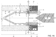
- Figures 1A to 1C show a first embodiment of a composite sealing dowel 1, which is suitable for sealing a penetration 35, such as a borehole, through a composite sealing system 30.
- the shows Figure 1A a sectional view along the longitudinal axis of the composite sealing dowel before screwing in a screw 20 and Figure 1C the same sectional view after screw 20.
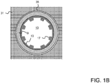
- Figure 1B shows a cross-sectional view through the view Figure 1A along the section line AA.
- the composite sealing system 30 shown in this embodiment has a 0.5 mm thick sealing membrane 32 which is applied to a structure in the form of a wall 31.
- the sealing membrane 32 supports tiles 34 with a thickness of 10 mm by means of a 3 mm thick layer of tile adhesive 33.
- the penetration 34 which in the embodiment shown has an inner diameter 34D of 10 mm, completely penetrates the sealing membrane 32, the tile adhesive 33 and the tiles 34 and penetrates into the wall 31.
- the composite sealing dowel 1 is essentially formed by a hollow cylindrical base body 10 made of polyamide.
- the base body 10 has an opening 13 for the screw 20.
- the first end 11 is followed by a section A3, in which the base body 10 has a radially outwardly directed flange.
- This section A3 extends in the embodiment shown by 1 mm in the axial direction.
- This flange-forming section A3 is followed by a (first) section A1, in which the base body 10 has on its radially outer lateral surface 14 an elastic sealant in the form of an annular elastomer body 19 made of rubber.
- This ring-shaped elastomer body 19 extends in the axial direction of the base body over 12 mm and thus has a greater longitudinal extent than the thickness of the composite seal 30.
- the annular elastomer body 19 is inserted in the axial direction to 90% in a recess 16 which is formed on the radially outer lateral surface 14 of the base body 10 and extends all around the base body 10 in the circumferential direction.
- a depth 16H of the recess in relation to the adjacent lateral surface 14 of the base body 10 is approximately 1 mm.
- the recess 16 fixes the position of the elastomer body 19 relative to the base body 10.
- the end of the recess 16 facing the first end 11 of the base body 10 is delimited by the flange.
- the (first) section A1 defined by the annular elastomer body 19 is adjoined in the axial direction of the base body 10 by a (second) section A2, which is free of the elastomer body 19, and at the first end 11 thereof in the axial direction of the opposite second End 12 of the base body 10 is closed and has a tip.
- the tip facilitates insertion of the base body 10 into the penetration 35.
- the lateral surface of the base body 10 is penetrated by a pair of slots oriented in the axial direction; these are in the Figures 1A and 1C can be seen in the area of the tip of the base body 10.
- the base body 10 has in this section A2 on its radially outer circumferential surface grooves which are oriented in the circumferential direction and which alternate in the axial direction with projections oriented in the circumferential direction.
- the base body 10 has, in the (first) section A1 defined by the ring-shaped elastomer body 19, on its radially inner lateral surface 15, projections 17 which are radially opposite the adjacent lateral surface 15 by a height 17H of 1 mm and in extend in the axial direction over the entire length of the annular elastomer body 19.
- FIG. 1B it can be clearly seen that eight projections 17 are arranged distributed uniformly in the circumferential direction of the base body 10 and are formed in one piece with the base body 10. It is emphasized that in the Figure 1B For the sake of clarity, the cross-sectional view shown is shown only for the opening 13 of the base body 10 for the screw 20, and not for the inner wall of the tip of the base body 10 that is spaced axially from the section line AA.
- the projections 17 favor that the ring-shaped elastomer body 19 is pressed radially outward of the base body 10 when the screw 20 is screwed into the composite sealing dowel 1, thus producing a press seal for the penetration 35 and in particular for the composite seal 30.
- the annular elastomer body 19 penetrates into gaps and cracks in the penetration 35, which is shown in Figure 1C is symbolically illustrated by the area marked with the reference number 19 *. Since the ring-shaped elastomer body 19 is arranged not only in the area of the sealing sheet 32 of the composite seal 30, but in the axial direction of the penetration 35 on both sides of the sealing sheet 32, it acts Composite sealing dowel 1 across layers.
- an outer diameter 1D of the composite sealing dowel 1 can be adapted to an inner diameter 35D of the penetration 35 and an outer diameter 20D of the screw 20 can be adapted to an inner diameter of the composite sealing dowel 1.
- an annular elastomer body 19 provided on the radially outer lateral surface 14 of the base body 10 an annular elastomer body can also be provided on the radially inner lateral surface of the base body 10, which provides the seal against the screw. However, this is not specifically shown in the figures.
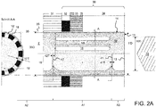
- Figures 2A and 2 B a second embodiment of a composite sealing dowel 1 ', which is suitable for sealing a penetration 35 through a composite sealing system 30, is explained.
- Figure 2A shows on the right a sectional view along the longitudinal axis of the composite sealing dowel 1 'before screwing in a screw 20 and on the left a cross-sectional view along the section line AA through the right figure.
- Figure 2B shows the same views after screw 20 has been screwed in.
- the sealing layer 32 of the composite sealing system 30 is not formed by a sealing membrane but by a 2 mm thick layer of a formerly liquid sealing material which has been applied to a drywall 31.
- the tile adhesive 33 and the tiles 34 of the composite sealing system 30 correspond to the first embodiment.
- the composite sealing dowel 1 ' also has a hollow cylindrical base body 10' made of polyamide and an opening 13 in the axial direction at a first end 11 for receiving a screw 20.
- the base body 10 ' is not shown over its entire length; in particular, an end opposite the first end 11 is not shown.
- the base body 10 'can have a shape which corresponds to the shape of the base body 10 according to the first embodiment in section A2 (which is free of sealant).
- the base body 10 'can be closed at its second end opposite the first end 11 in the axial direction.
- the base body 10 ' has a pasty sealant 19' made of MS polymer in its interior. On its outer surface in the radial direction, the base body 10 'is free of the pasty sealant 19'.
- the presence of this sealant 19 ' also defines a (first) section A1 of the base body 10' in the axial direction in this embodiment.
- an outer wall of the base body 10 ' has twelve elongated holes 18 which are arranged uniformly distributed from one another in the circumferential direction of the base body 10'. Longitudinal axes of the elongated holes 18 are oriented in the axial direction of the base body 10 '.
- the length 18L of the elongated holes 18 is 13 mm in each case in the embodiment shown and thus exceeds the thickness of conventional composite sealing systems 30.
- the (first) section A1 in which the pasty sealant 19 'is arranged, is delimited by first and second partition walls 41, 42.
- the first partition 41 closes the pasty sealant 19 'from the opening 13 of the base body 10'
- the second partition 42 closes the pasty sealant 19 'from a (second) section A2 of the base body 10' which is free of sealant.
- the second partition 42 was in front of one Filling of pasty sealant 19 'and the first partition 41 welded after filling of pasty sealant 19' with an inner wall of the base body 10 '.
- the partitions 41 and 42 have wall thicknesses 41T and 42T, which correspond to only 15% of an average wall thickness 10'T of the base body 10 '.
- an average wall thickness 10'T (here corresponds to the average thickness of the outer wall) of the base body 10 ', the radial distance between a smallest circle defined by a radially outer circumferential surface 14 of the base body 10' and one of a radially inner circumferential surface of the base body 10 'understood the largest circle, whereby the centers of both circles coincide.
- the partition walls 41 and 42 can be easily penetrated by the screw 20.
- section A3 which is free of sealant, and is adjacent to the first end 11 of the base body 10 ′ with the opening 13, in the second embodiment a substantially larger longitudinal extension of around 4 mm and has no flange. The greater length of this section A3 prevents pasty sealant 19 'from being pressed out of the penetration 35.
- the screw 20 When the screw 20 is inserted into the opening 13 of the base body 10 ', the screw first presses an outer wall of the base body 10' outwards in section A3 and thus provides a certain press seal to an inner wall of the penetration 35. The screw 20 then destroys the first partition 41 and presses the pasty sealant 19 'via the elongated holes 18 outside the base body 10', since the pasty sealant 19 'is prevented by the second partition 42 from evading in the axial direction. A resulting filling zone for the pasty sealant 19 'is shown in Figure 2B shown schematically.
- the backfill zone not only extends in the area of the sealing layer 32 of the composite sealing system 30, but also in the axial direction of the penetration 35 on both sides of the sealing layer 32 the composite sealing dowel 1 here also across layers.
- the screw 20 also destroys the second partition 42 and penetrates into the section A2 of the base body 10 'free of sealant.
- the latter section A2 is used in particular for the mechanical fastening of the composite sealing dowel 1 'in the penetration 35.
- an outer diameter 20D of the screw 20 is to be adapted to an inner diameter of the base body 10 'of the composite sealing dowel 1' and an outer diameter 1'D of the composite sealing dowel 1 'to an inner diameter 35D of the penetration 35 and thus to be suitably selected ,
- Figures 3A and 3B a third embodiment of a composite sealing dowel 1 ", which for sealing a penetration 35 through a composite sealing system 30 is explained.
- Figure 3A shows a sectional view along the longitudinal axis of the composite sealing dowel 1 "before screwing in a screw 20 and
- Figure 3B branches the same view after screwing in screw 20.
- the composite sealing system 30 corresponds to the composite sealing system of the first embodiment and has a sealing membrane 32 applied to a wall 31, which carries tiles 34 by means of tile adhesive 33.
- the hollow cylindrical base body 10 "of the composite sealing dowel 1" is formed on its radially inner and outer surfaces from elastomer layers 101, 103 of rubber.
- the composite sealing dowel 1 "thus has elastomer both along its entire axial extent and in the circumferential direction on its outer surfaces.
- a core made of a polyamide layer 102 with a radial direction between the elastomer layers 101, 103 Measured wall thickness of 0.5 mm is provided, which gives the composite sealing dowel 1 "stability in the axial direction and prevents a screw from completely destroying the elastomer layers 101, 103.
- the core 102 is only optional.
- the composite sealing dowel 1 can therefore alternatively also be formed entirely from elastomer.
- the thickness of the elastomer layers 101, 103 on the outer surfaces of the composite sealing dowel 1" is measured starting from the polyamide layer 102 in the radial direction, both for the penetration 35 as well as the screw 20 each 1.5 mm.
- the elastomer When the screw 20 is screwed in, the elastomer is applied to the inner wall of the penetration 35 across all layers of the composite sealing system 30 and the outer wall of the screw 20 are pressed and the penetration 35 is thus completely sealed against the ingress of water.
- the composite sealing dowel 1 unlike in the first embodiment, the composite sealing dowel 1 "does not have a flange surrounding its opening 13 for the screw 20. One such can optionally be provided. Furthermore, the composite sealing dowel 1" has a different way than in FIG Figure 1 shown no tip, but is hollow cylindrical. However, a tip can be provided in order to facilitate the introduction of the composite sealing dowel 1 "into the penetration 35.
- the composite sealing dowel of the first or third embodiment additionally has pasty sealing material in its interior and corresponding openings / weakenings in the lateral surface, which allow the pasty sealing material to escape radially when a screw is screwed in.
- Partition walls can also be provided which limit the pasty sealing material.
- the composite sealing dowel of the second embodiment can have on its radially outer and / or radially inner circumferential surface adjacent to the opening for the screw a particularly annular elastic sealant, which produces a press seal to the inner wall of the penetration or to the screw when screwing in a screw, and so on Prevents pasty sealant pressed out of the composite sealing dowel from escaping from the penetration.
- the present document discloses a composite sealing dowel for sealing a penetration through a composite sealing system, with a hollow cylindrical base body.
- the base body faces axially Direction at a first end to an opening for receiving a screw.
- the base body has at least in one section an elastic or plastic sealant, the sealant 19, 19 'being formed from a material which differs from the material from which the base body is formed and when the screw is screwed into the composite seal -Dowel is pressed radially outwards of the base body.
- the entire base body is formed from an elastic sealant.
- the interaction of the composite sealing dowel and the screw ensures that the tightness required for a particular stress class of the composite sealing system is also ensured in the area of penetration.
Landscapes
- Engineering & Computer Science (AREA)
- General Engineering & Computer Science (AREA)
- Mechanical Engineering (AREA)
- Building Environments (AREA)
- Gasket Seals (AREA)
- Dowels (AREA)
Abstract
Description
- Die Erfindung betrifft einen Verbundabdichtungs-Dübel. Dabei wird unter einem Verbundabdichtungs-Dübel ein Schraubdübel verstanden, der zwischen einer Schraube und einem Baukörper, in dem der Schraubdübel angeordnet ist, insbesondere im Hinblick auf Feuchtigkeit und Flüssigkeiten eine Dichtwirkung entfaltet. Dabei durchdringt der Schraubdübel eine in dem Baukörper vorgesehene Verbundabdichtung und dichtet gegenüber dieser Verbundabdichtung zuverlässig und dauerhaft ab.
- Gemäß der Normen DIN 19 531, DIN 19 532, DIN 19 533 und DIN 19 534 sind Bauwerke und Bauteile so zu planen und auszuführen, dass keine Schäden durch Wasser oder Feuchtigkeit entstehen. In der Folge ist die Bausubstanz durch geeignete Abdichtungsmaßnahmen zu schützen.
- Hierfür werden häufig Verbundabdichtungssysteme mit einer Schutzschicht aus keramischen Belags- und Bekleidungsbaustoffen bzw. Natur- oder Betonwerksteinfliesen verwendet. Diese setzen sich in der Regel aus einer keramischen Fliese oder Platte, Fugenmörtel zwischen den Fliesen oder Platten, unter der Fliese oder Platte befindlichem Fliesenkleber und einer Abdichtung zusammen. Die Abdichtung ist in der Regel zwischen dem Fliesenkleber und einem Baukörper (einer Wand oder einem Boden, beispielsweise aus Ziegel oder Beton) angeordnet und mit dem Baukörper verklebt. Für die Abdichtung werden im Lieferzustand pulverförmige, pastöse, flüssige oder bahnenförmige Abdichtungsstoffe verwendet. Geeignete flüssige Abdichtungsstoffe können in unterschiedlichen Ausgestaltungen, beispielsweise unter den Bezeichnungen FlächenDicht flexibel (FDF), DichtSchlämme Flex (DSF), TurboDichtSchlämme (TDS) oder PU-FlächenDicht (PU-FD), von der Sopro Bauchemie GmbH, Wiesbaden, Deutschland bezogen werden. Geeignete bahnenförmige Abdichtungsstoffe können in unterschiedlichen Ausgestaltungen, beispielsweise unter der Bezeichnung Abdichtungs- und EntkopplungsBahn AEB (geschütztes Warenzeichen) oder Abdichtungs- und Entkopplungsbahn plus (geschütztes Warenzeichen), von der Sopro Bauchemie GmbH, Wiesbaden, Deutschland bezogen werden. Derartige bahnenförmige Abdichtungsstoffe bestehen beispielsweise aus reißfester Polypropylenfolie mit einer beidseitigen speziellen Vliesgewebebeschichtung aus Polypropylen und einer Dicke von ca. 0,3 mm bis 0,9 mm.
- Eine besondere Problematik stellen bei Verbundabdichtungssystemen nachträglich eingebrachte Durchdringungen wie insbesondere Bohrlöcher dar, da diese die Verbundabdichtung typischerweise bis hin zum Baukörper durchdringen. Auch bei derartigen nachträglich eingebrachten Durchdringungen muss die Dichtigkeit des Verbundabdichtungssystems gewährleistet werden.
- Es besteht daher ein Bedarf daran, Mittel bereitzustellen, welche eine Abdichtung von nachträglich in Verbundabdichtungssystemen eingebrachten Durchdringungen auf einfache und zuverlässige Weise ermöglichen. Gemäß einer Ausführungsform sollten die Mittel auch nach Durchdringung des Verbundabdichtungssystems eine für eine jeweilige Beanspruchungsklasse gegen Wasser oder Feuchtigkeit geforderte Dichtigkeit sicher erfüllen.
- Die vorstehende Aufgabe wird durch einen Verbundabdichtungs-Dübel mit den Merkmalen der unabhängigen Ansprüche gelöst. Bevorzugte Weiterbildungen finden sich in den abhängigen Ansprüchen.
- Gemäß aller Ausführungsformen wird ein Verbundabdichtungs-Dübel (Schraubdübel) mit einem hohlzylindrischen Grundkörper bereitgestellt. Dabei muss der hohlzylindrische Grundkörper kein im mathematischen Sinn perfekter Hohlzylinder sein. Zudem kann der Hohlzylinder einseitig geschlossen und am geschlossenen Ende verrundet sein. Auch ist es zulässig, dass eine Mantelfläche des Hohlzylinders Durchdringungen, Vertiefungen oder Vorsprünge aufweist. Dabei weist der Grundkörper in axialer Richtung an einem ersten Ende eine Öffnung zur Aufnahme einer Schraube auf. Beim Eindrehen der Schraube spreizt sich der Verbundabdichtungs-Dübel. Durch Kraftschluss zwischen Verbundabdichtungs-Dübel und umgebenden Material ist die Schraube gegen Herausziehen gesichert. Weiter formt die Schraube im inneren Teil des Verbundabdichtungs-Dübels ein Gegengewinde, wobei sie das Material, aus dem der Verbundabdichtungs-Dübel gebildet ist, plastisch verformt und zusätzlich radial nach außen verdrängt und so den Verbundabdichtungs-Dübel spreizt.
- Gemäß einer ersten Ausführungsform weist der Grundkörper in axialer Richtung einen ersten Abschnitt und einen zweiten Abschnitt auf, wobei der erste Abschnitt zwischen dem zweiten Abschnitt und dem ersten Ende des Grundkörpers angeordnet ist. An seiner radial außenliegenden Mantelfläche weist der Grundkörper im ersten Abschnitt einen elastischen Dichtstoff auf. Im zweiten Abschnitt ist der Grundkörper an seiner radial außenliegenden Mantelfläche hingegen frei von dem elastischen Dichtstoff. Dabei ist der elastische Dichtstoff aus einem Material gebildet, welches sich von dem Material, aus welchem der Grundkörper gebildet ist, unterscheidet. Somit werden die ersten und zweiten Abschnitte durch das Vorhandensein bzw. die Abwesenheit von elastischem Dichtstoff festgelegt. Beim Einschrauben einer Schraube in den Verbundabdichtungs-Dübel wird der elastische Dichtstoff radial nach außen gedrückt. Freie Räume in einer Durchdringung, in welche der Verbundabdichtungs-Dübel eingesetzt ist, werden vom elastischen Dichtstoff ausgefüllt, wodurch die Durchdringung gegenüber dem Verbundabdichtungs-Dübel und der Schraube abgedichtet wird. Weiter entsteht so auch ein Formschluss gegen Herausziehen des Verbundabdichtungs-Dübels.
- Durchsetzt die Durchdringung dabei eine Verbundabdichtung, die wie vorstehend beschrieben aus einer Schutzschicht aus einer keramischen Fliese oder Platte bzw. einem Natur- oder Betonwerkstein, Fugenmörtel zwischen den Fliesen oder Platten, unter der Fliese oder Platte befindlichem Fliesenkleber und einer Abdichtung gebildet ist, bewirkt der im ersten Abschnitt vorhandene elastische Dichtstoff eine Dichtwirkung, welche in axialer Richtung des Verbundabdichtungs-Dübels die Abdichtung der Verbundabdichtung und Abschnitte zu beiden Seiten der Abdichtung umfasst und somit schichtübergreifend wirkt.
- Gemäß einer Ausführungsform weist das den Grundkörper bildende Material im ersten Abschnitt an der radial außenliegenden Mantelfläche des Grundkörpers einen sich in axialer und radialer Richtung erstreckenden Rücksprung auf, in welchen der elastische Dichtstoff ganz oder teilweise eingesetzt ist. Da ein Rücksprung gegenüber der benachbarten radial außenliegenden Mantelfläche des Grundkörpers radial nach innen zurückversetzt ist, ist es durch ganzes oder teilweises Einsetzen des elastischen Dichtstoffes möglich, die Lage des elastischen Dichtstoffes in axialer Richtung des Grundkörpers zu fixieren. Weiter ist es hierdurch möglich, sicherzustellen dass eine radial außenliegende Mantelfläche des elastischen Dichtstoffes mit der radial außenliegenden Mantelfläche des Grundkörpers fluchtet (was bedeutet, dass beide Flächen bündig sind) oder gegenüber dieser nur geringfügig vorspringt. Dabei soll unter "geringfügig" verstanden werden, dass die radial außenliegende Mantelfläche des elastischen Dichtstoffes gegenüber der radial außenliegenden Mantelfläche des Grundkörpers um weniger als die mittlere Wandstärke des Grundkörpers vorspringt und insbesondere um weniger als die Hälfte der mittleren Wandstärke des Grundkörpers vorspringt. Gemäß einer Ausführungsform springt die radial außenliegende Mantelfläche des elastischen Dichtstoffes gegenüber der radial außenliegenden Mantelfläche des Grundkörpers um weniger als 1 mm und insbesondere um weniger als 0,5 mm vor. Der Begriff "eingesetzt" soll dabei sowohl ein nachträgliches Einsetzten eines separaten elastischen Dichtstoffes in Form eines Ringes als auch ein Umspritzen des Grundkörpers mit dem elastischen Dichtstoff umfassen.
- Gemäß einer Ausführungsform ist die mittlere Dicke der Außenwand des Grundkörpers der radiale Abstand zwischen einem von einer radial außenliegenden Mantelfläche des Grundkörpers festgelegten kleinsten Kreis zu einem von einer radial innenliegenden Mantelfläche des Grundkörpers festgelegten größten Kreis, wobei die Mittelpunkte beider Kreise zusammenfallen.
- Gemäß einer Ausführungsform erstreckt sich der Rücksprung in axialer Richtung über den ganzen ersten Abschnitt des Grundkörpers, was bedeutet, dass der elastische Dichtstoff über seine ganze axiale Erstreckung in den Rücksprung im Grundkörper eingesetzt ist.
- Gemäß einer alternativen Ausführungsform erstreckt sich der Rücksprung in axialer Richtung über zwischen 20 % und 90% oder über zwischen 40 % und 85% oder über zwischen 60 % und 80% des ersten Abschnitts des Grundkörpers, was bedeutet, dass der elastische Dichtstoff bezogen auf seine axiale Erstreckung nur teilweise in den Rücksprung im Grundkörper eingesetzt ist.
- Gemäß einer Ausführungsform erstreckt sich der Rücksprung in Umfangsrichtung vollständig um den Grundkörper herum; dann ist der eingesetzte elastische Dichtstoff für sich alleine betrachtet ringförmig.
- Gemäß einer Ausführungsform beträgt eine Tiefe des Rücksprungs im ersten Abschnitt in radialer Richtung zwischen 0,25 mm und 2,5 mm oder zwischen 0,5 mm und 2,25 mm oder zwischen 1,0 mm und 2,0 mm. Ein Rücksprung mit einer solchen Tiefe stellt sicher, dass ausreichend elastischer Dichtstoff um den Grundkörper herum angeordnet werden kann, um die beabsichtigte Dichtwirkung zu erzielen.
- Gemäß einer Ausführungsform weist der Grundkörper im ersten Abschnitt an seiner radial innenliegenden Mantelfläche einen sich in radialer und axialer Richtung erstreckenden Vorsprung auf. Indem der Grundkörper im Bereich des elastischen Dichtstoffes einen sich radial nach innen erstreckenden Vorsprung aufweist, wird sichergestellt, dass im Bereich des elastischen Dichtstoffes beim Eindrehen einer Schraube besonders viel Material radial nach außen verdrängt wird.
- Gemäß einer Ausführungsform erstreckt sich der Vorsprung in axialer Richtung über den ganzen ersten Abschnitt des Grundkörpers, und ist in der Folge in axialer Richtung an gleicher Position wie der elastische Dichtstoff angeordnet.
- Gemäß einer alternativen Ausführungsform erstreckt sich der Vorsprung in axialer Richtung über zwischen 25 % und 95% oder über zwischen 45 % und 90% oder über zwischen 65 % und 85% des ersten Abschnitts des Grundkörpers. Der Vorsprung kann in axialer Richtung des Grundkörpers entweder eine geringere Erstreckung als der elastische Dichtstoff aufweisen und vollständig im ersten Abschnitt liegen oder auch gegenüber dem ersten Abschnitt in axialer Richtung versetzt sein. Falls der Vorsprung gegenüber dem ersten Abschnitt in axialer Richtung versetzt ist, kann der Vorsprung sogar größer als der erste Abschnitt sein.
- Gemäß einer Ausführungsform erstreckt sich der Vorsprung in Umfangsrichtung vollständig innerhalb des Grundkörpers herum. Gemäß einer alternativen Ausführungsform sind in Umfangsrichtung verteilt mehrere voneinander getrennte Vorsprünge vorgesehen. Die Verwendung von mehreren in Umfangsrichtung verteilt angeordneten Vorsprüngen vermeidet zu große Wandstärken des Grundkörpers.
- Gemäß einer Ausführungsform beträgt eine Höhe des Vorsprungs in radialer Richtung gegenüber der radial innenliegenden Mantelfläche des Grundkörpers zwischen 0,25 mm und 2,5 mm oder zwischen 0,5 mm und 2,25 mm oder zwischen 1,0 mm und 2,0 mm. Gemäß einer Ausführungsform ist die Höhe des Vorsprungs in radialer Richtung kleiner oder gleich der Dicke es elastischen Dichtstoffs in radialer Richtung.
- Gemäß einer Ausführungsform weist der Grundkörper im ersten Abschnitt an seiner radial innenliegenden Mantelfläche ebenfalls einen elastischen Dichtstoff auf. Indem der Grundkörper auch in seinem Inneren einen elastischen Dichtstoff aufweist, wird die Dichtwirkung gegenüber einer in den Verbundabdichtungs-Dübel eingedrehten Schraube verbessert.
- Gemäß einer Ausführungsform erstreckt sich der im ersten Abschnitt an der radial innenliegenden Mantelfläche angeordnete elastische Dichtstoff in axialer Richtung über den ganzen ersten Abschnitt des Grundkörpers.
- Gemäß einer Ausführungsform umgibt der elastische Dichtstoff den Grundkörper an seiner radial außenliegenden Mantelfläche und/oder an seiner radial innenliegenden Mantelfläche in Umfangsrichtung des Grundkörpers vollständig, und bildet so jeweils einen Ring.
- Gemäß einer Ausführungsform ist der elastische Dichtstoff ein Elastomerkörper, der den Grundkörper an seiner radial außenliegenden Mantelfläche und/oder an seiner radial innenliegenden Mantelfläche in Umfangsrichtung des Grundkörpers vollständig umgibt, und so einen Ring bildet. Gemäß einer Ausführungsform ist der Elastomerkörper eine Kautschuk-Art, Perfluorkautschuk (FFKM oder FFPM), Polyethylen (PE) oder Polytetrafluorethylen (PTFE).
- Gemäß einer zweiten Ausführungsform, welche auch mit der vorstehenden ersten Ausführungsform kombiniert werden kann, weist der hohlzylindrische Grundkörper des Verbundabdichtungs-Dübels mit der Öffnung für die Schraube in seinem Inneren einen pastösen Dichtstoff auf. Da der Grundkörper von Verbundabdichtungs-Dübeln typischerweise nicht aus pastösem Material besteht, ist der Dichtstoff somit aus einem Material gebildet, welches sich von dem Material, aus welchem der Grundkörper gebildet ist, unterscheidet. Weiter weist eine Außenwand des Grundkörpers mehrere Durchbrüche und/oder Schwächungen auf. Dabei wird unter einer "Schwächung" gemäß einer Ausführungsform ein Bereich verstanden, in dem eine Dicke der Außenwand um wenigstens 50 % und insbesondere um wenigstens 75% und weiter insbesondere um wenigstens 90% gegenüber der mittleren Dicke der Außenwand an dieser Stelle reduziert ist. Beim Eindrehen einer Schraube in die Öffnung des Verbundabdichtungs-Dübels wird der pastöse Dichtstoff durch die Durchbrüche / Schwächungen in der Außenwand des Grundkörpers hindurch aus dem Inneren des Grundkörpers radial nach außerhalb des Grundkörpers gedrückt. In der Folge werden freie Räume in einer Durchdringung, in welche der Verbundabdichtungs-Dübel eingesetzt ist, vom pastösen Dichtstoff ausgefüllt, wodurch die Durchdringung gegenüber dem Verbundabdichtungs-Dübel und der Schraube abgedichtet wird.
- Durchsetzt die Durchdringung dabei eine Verbundabdichtung, bewirkt der nach außerhalb des Grundkörpers gepresste pastöse Dichtstoff eine Dichtwirkung, welche in axialer Richtung des Verbundabdichtungs-Dübels die Verbundabdichtung und Abschnitte zu beiden Seiten der Verbundabdichtung umfasst und somit schichtübergreifend wirkt. Gleichzeitig bewirkt im Inneren des Grundkörpers verbleibender pastöser Dichtstoff eine gute Abdichtung gegenüber einer in den Verbundabdichtungs-Dübel eingedrehten Schraube.
- Gemäß einer Ausführungsform ist der Verbundabdichtungs-Dübel außerhalb des Grundkörpers frei von pastösem Dichtstoff.
- Gemäß einer Ausführungsform ist der pastöse Dichtstoff in einem in axialer Richtung des hohlzylindrischen Grundkörpers mit der Öffnung für die Schraube ersten Ende vorgesehen.
- Gemäß einer Ausführungsform ist der hohlzylindrische Grundkörper in axialer Richtung vollständig oder zu wenigstens 2/3 oder zu wenigstens der Hälfte oder zu wenigstens einem Drittel mit dem pastösen Dichtstoff gefüllt.
- Gemäß einer Ausführungsform sind die Durchbrüche und/oder Schwächungen voneinander in Umfangsrichtung beabstandet.
- Gemäß einer Ausführungsform sind die Durchbrüche und/oder Schwächungen in Umfangsrichtung gleichmäßig um den Grundkörper herum verteilt angeordnet. Dabei sind die Durchbrüche Langlöcher, deren Längsachsen in axialer Richtung des Grundkörpers orientiert sind oder mit der axialen Richtung des Grundkörpers einen Winkel von zwischen 5 ° und 60 ° einschließen oder mit der axialen Richtung des Grundkörpers einen Winkel von zwischen 5 ° und 30 ° einschließen. Weiter sind die Schwächungen Langnuten, deren Längsachsen in axialer Richtung des Grundkörpers orientiert sind oder mit der axialen Richtung des Grundkörpers einen Winkel von zwischen 5 ° und 60 ° einschließen oder mit der axialen Richtung des Grundkörpers einen Winkel von zwischen 5 ° und 30 ° einschließen. Durch die weitgehend axiale Orientierung der Durchbrüche / Schwächungen wird eine Herabsetzung der von dem Verbundabdichtungs-Dübel in axialer Richtung aufnehmbaren Zugkraft gering gehalten.
- Gemäß einer Ausführungsform weist der Grundkörper eine erste Trennwand auf, welche zwischen dem pastösen Dichtstoff und dem ersten Ende des Grundkörpers angeordnet ist und den pastösen Dichtstoff gegenüber der Öffnung des Grundkörpers abschließt. Auf diese Weise kann ein Austrocknen oder Aushärten des pastösen Dichtstoffes vermieden werden. Gemäß einer Ausführungsform ist die erste Trennwand einstückig mit dem Grundkörper gebildet. Gemäß einer alternativen Ausführungsform ist die erste Trennwand in den Grundkörper eingepresst oder eingeklebt oder eingeschweißt oder eingelegt. Es wird betont, dass die Trennwand auch die Form eines Pfropfens aufweisen und so ausgebildet sein kann, dass sie aus dem Grundkörper entfernt werden kann.
- Gemäß einer Ausführungsform weist der Grundkörper eine zweite Trennwand auf, welche in axialer Richtung von der ersten Trennwand beabstandet ist. Dann kann der pastöse Dichtstoff zwischen der ersten Trennwand und der zweiten Trennwand angeordnet sein. In diesem Fall dienen die beiden Trennwände zur Begrenzung des Abschnitts, in welchem der pastöse Dichtstoff vorhanden ist. Gemäß einer Ausführungsform ist die zweite Trennwand einstückig mit dem Grundkörper gebildet. Gemäß einer alternativen Ausführungsform ist die zweite Trennwand in den Grundkörper eingepresst oder eingeklebt oder eingeschweißt oder eingelegt.
- Gemäß einer Ausführungsform ist eine Dicke der (ersten und/oder zweiten) Trennwand gegenüber einer mittleren Dicke der Außenwand des Grundkörpers um wenigstens 50 % oder um wenigstens 75% oder um wenigstens 90% reduziert. Auf diese Weise ist sichergestellt, dass die (erste und/oder zweite) Trennwand leicht von einer Schraube durchdrungen werden können. Gemäß einer Ausführungsform ist die Dicke der zweiten Trennwand größer oder gleich der Dicke der ersten Trennwand.
- Gemäß einer Ausführungsform ist der pastöse Dichtstoff ein Butylkautschuk-Dichtstoff oder ein Polysulfid-Dichtstoff oder ein Silikon-Dichtstoff oder ein Polyurethan-Dichtstoff oder ein MS-Polymer-Dichtstoff oder ein Harz. Derartige Materialien sind sicher zu verarbeiten, lassen sich gut mit Verbundabdichtungssystemen kombinieren und weisen gute und dauerhafte Dichtungseigenschaften auf.
- Gemäß einer Ausführungsform weist der Grundkörper in axialer Richtung einen Abschnitt auf, in dem der Grundkörper frei von Dichtstoff ist, wobei dieser Abschnitt an das erste Ende des Grundkörpers angrenzt und sich von dem ersten Ende um zwischen 1 mm und 10 mm oder um zwischen 2,5 mm und 8 mm oder um zwischen 3 mm und 6 mm in axialer Richtung erstreckt. Auf diese Weise wird vermieden, dass der Dichtstoff nach außerhalb einer Durchdringung, in welche der Verbundabdichtungs-Dübel eingesetzt ist, dringt.
- Gemäß einer Ausführungsform erstreckt sich der Abschnitt des Grundkörpers, in welchem der Grundkörper Dichtstoff aufweist, über zwischen 5 mm und 30 mm oder über zwischen 7 mm und 20 mm oder über zwischen 10 mm und 15 mm in axialer Richtung.
- Gemäß einer Ausführungsform erstreckt sich der Abschnitt des Grundkörpers, in welchem der Grundkörper Dichtstoff aufweist, in axialer Richtung über zwischen 20 % und 70 % der Gesamtlänge des Grundkörpers oder über zwischen 30 % und 60 % der Gesamtlänge des Grundkörpers oder über zwischen 40 % und 50 % der Gesamtlänge des Grundkörpers.
- Auf diese Weise ist der Verbundabdichtungs-Dübel gut zur Abdichtung von in Verbundabdichtungssystemen eingebrachten Durchdringungen angepasst, da eine derartige axiale Erstreckung des Dichtstoffs schichtübergreifend wirken kann, indem in axialer Richtung des Verbundabdichtungs-Dübels im Bereich der Abdichtung der Verbundabdichtung und zu beiden Seiten der Abdichtung Dichtstoff angeordnet ist.
- Gemäß einer Ausführungsform ist der Grundkörper aus Kunststoff und insbesondere aus Polyamid oder aus Metall gebildet.
- Gemäß weiterer Ausführungsformen, die mit den vorstehenden Ausführungsformen kombiniert werden können, weist ein Verbundabdichtungs-Dübel einen hohlzylindrischen Grundkörper mit einer an einem in axialer Richtung ersten Ende angeordneten Öffnung zur Aufnahme einer Schraube auf. Dabei weist der Grundkörper an seinen radial innenliegenden und radial außenliegenden Außenflächen jeweils Elastomer-Schichten auf, die sowohl in axialer Richtung als auch in Umfangsrichtung des Verbundabdichtungs-Dübels durchgehend ausgebildet sind. Dabei kann es sich auch um eine einzige gemeinsame Elastomer-Schicht handeln; somit kann der Grundkörper insgesamt aus Elastomer gebildet sein. Gemäß einer Ausführungsform beträgt eine Erstreckung des hohlzylindrischen Grundkörpers in axialer Richtung wenigstens 10 mm oder wenigstens 15 mm.
- Aufgrund seiner Elastomer-Schichten weist der Verbundabdichtungs-Dübel gute Dichteigenschaften sowohl gegenüber einer Innenwand der Durchdringung als auch gegenüber einer über die Öffnung im Grundkörper eingeführten Schraube auf. Durchsetzt die Durchdringung dabei eine Verbundabdichtung, die wie vorstehend beschrieben aus einer keramischen Fliese oder Platte, Fugenmörtel zwischen den Fliesen oder Platten, unter der Fliese oder Platte befindlichem Fliesenkleber und einer Abdichtung gebildet sein kann, bewirkt die an der radial außenliegenden Außenfläche vorhandene Elastomer-Schicht eine Dichtwirkung, welche in axialer Richtung des Verbundabdichtungs-Dübels die Abdichtung der Verbundabdichtung und Abschnitte zu beiden Seiten der Abdichtung umfasst und somit schichtübergreifend wirkt.
- Gemäß einer Ausführungsform weist der Grundkörper zwischen seinen radial innenliegenden und radial außenliegenden Elastomer-Schichten eine Schicht aus Polyamid oder Metall auf. Ein solcher Kern erhöht die Stabilität des Verbundabdichtungs-Dübels erheblich und erleichtert so ein Einführen des Verbundabdichtungs-Dübels entlang seiner axialen Richtung in eine Durchdringung. Weiter verhindert ein solcher Kern, dass die Elastomer-Schichten durch eine Schraube versehentlich in radialer Richtung ganz durchdrungen werden.
- Gemäß einer Ausführungsform beträgt die Dicke jeder Elastomer-Schicht in radialer Richtung zwischen 1 mm und 3 mm oder zwischen 1,5 mm und 2 mm.
- Gemäß einer Ausführungsform beträgt die Dicke der Schicht aus Polyamid oder Metall in radialer Richtung zwischen 0,25 mm und 1,5 mm oder zwischen 0,4 mm und 0,8 mm.
- Gemäß einer Ausführungsform weist der Grundkörper in einem Abschnitt, der optional frei von Dichtstoff ist, wenigstens ein Paar von in axialer Richtung verlaufenden Schlitzen auf, welche eine Mantelfläche des Grundkörpers durchdringen. Diese Schlitze erleichtern ein Aufspreizen des Verbundabdichtungs-Dübels in dem Abschnitt.
- Gemäß einer Ausführungsform weist der Grundkörper in einem Abschnitt, der optional frei von Dichtstoff ist, auf seiner radial außenliegenden Mantelfläche in Umfangsrichtung orientierte Rillen auf, welche sich in axialer Richtung mit in Umfangsrichtung orientierten Vorsprüngen abwechseln. Eine derartige Oberfläche kann sich gut mit der Innenwand einer Durchdringung, in welche der Verbundabdichtungs-Dübel eingesetzt ist, verzahnen.
- Gemäß einer Ausführungsform weist der Grundkörper an seinem ersten Ende benachbart zur Öffnung einen radial nach außen gerichteten Flansch auf. Ein solcher Flansch verhindert, dass der Verbundabdichtungs-Dübel zu tief in eine Durchdringung eingesetzt wird. Zudem schließt ein solcher Flansch die Durchdringung optisch ab.
- Gemäß einer Ausführungsform ist der Grundkörper an seinem dem ersten Ende in axialer Richtung gegenüberliegenden zweiten Ende geschlossen. Dabei kann dieses zweite Ende auch verrundet sein, um ein Einführen des Verbundabdichtungs-Dübels in eine Durchdringung zu erleichtern.
- Ausführungsformen eines Verfahrens zur Abdichtung einer Durchdringung durch ein Verbundabdichtungssystem weisen die Schritte des Bereitstellens eines Verbundabdichtungs-Dübels wie vorstehend beschrieben, des Einsetzens des Verbundabdichtungs-Dübels in die Durchdringung, des Bereitstellens einer Schraube und des Einschraubens der Schraube in den Grundkörper des Verbundabdichtungs-Dübels auf. Dabei ist ein Außendurchmesser des Grundkörpers des Verbundabdichtungs-Dübels an einen Innendurchmesser der Durchdringung und ein Außendurchmesser der Schraube an einen Innendurchmesser des Grundkörpers des Verbundabdichtungs-Dübels angepasst.
- Der vorstehend beschriebene Verbundabdichtungs-Dübel ist besonders gut für eine Verwendung zur Abdichtung einer Durchdringung durch ein Verbundabdichtungssystem geeignet, da Dichtstoff in axialer Richtung des Verbundabdichtungs-Dübels im Bereich der Abdichtung der Verbundabdichtung und zu beiden Seiten der Abdichtung angeordnet ist und ein derartiger Verbundabdichtungs-Dübel somit schichtübergreifend wirken kann.
- Ausführungsformen eines Systems zur Abdichtung einer Durchdringung durch ein Verbundabdichtungssystem, weisen einen in die Durchdringung eingesetzten Verbundabdichtungs-Dübel und eine in den Verbundabdichtungs-Dübel eingedrehte Schraube auf. Dabei sind der Verbundabdichtungs-Dübel und die Schraube gemeinsam ausgebildet, eine für eine jeweilige Beanspruchungsklasse des Verbundabdichtungssystems geforderte Dichtigkeit auch im Bereich der Durchdringung sicherzustellen. Bei dem Verbundabdichtungs-Dübel handelt es sich gemäß einer Ausführungsform um den vorstehend beschriebenen Verbundabdichtungs-Dübel.
- Ausführungsformen der Erfindung werden nachfolgend anhand von Figuren näher erläutert. Hierbei zeigt:
- Figuren 1A und 1C
- Schnittansichten durch einen Verbundabdichtungs-Dübel gemäß einer ersten Ausführungsform in unterschiedlichen Betriebszuständen;
- Figur 1B
- eine Querschnittsansicht entlang der Schnittlinie A-A durch den Aufbau aus
Figur 1A ; - Figuren 2A und 2B
- Schnittansichten und Querschnittsansichten durch einen Verbundabdichtungs-Dübel gemäß einer zweiten Ausführungsform in unterschiedlichen Betriebszuständen; und
- Figuren 3A und 3B
- Schnittansichten und Querschnittsansichten durch einen Verbundabdichtungs-Dübel gemäß einer dritten Ausführungsform in unterschiedlichen Betriebszuständen.
- In den Figuren werden gleiche oder ähnliche Elemente mit den gleichen oder ähnlichen Bezugszeichen bezeichnet.
-
Figuren 1A bis 1C zeigen eine erste Ausführungsform eines Verbundabdichtungs-Dübels 1, welcher zur Abdichtung einer Durchdringung 35, wie beispielsweise eines Bohrloches, durch ein Verbundabdichtungssystem 30 geeignet ist. Dabei zeigt dieFigur 1A eine Schnittansicht entlang der Längsachse des Verbundabdichtungs-Dübels vor einem Eindrehen einer Schraube 20 undFigur 1C die gleiche Schnittansicht nach Eindrehen der Schraube 20.Figur 1B zeigt eine Querschnittsansicht durch die Ansicht ausFigur 1A entlang der Schnittlinie A-A. - Das in dieser Ausführungsform gezeigte Verbundabdichtungssystem 30 weist eine 0,5 mm starke Abdichtungsbahn 32 auf, welche auf einen Baukörper in Form einer Mauer 31 aufgebracht ist. Die Abdichtungsbahn 32 trägt mittels einer 3 mm starken Schicht Fliesenkleber 33 Fliesen 34 mit einer Stärke von 10 mm. Die Durchdringung 34, welche in der gezeigten Ausführungsform einen Innendurchmesser 34D von 10 mm aufweist, durchdringt die Abdichtungsbahn 32, den Fliesenkleber 33 und die Fliesen 34 vollständig und dringt in die Mauer 31 ein.
- Der Verbundabdichtungs-Dübel 1 wird im Wesentlichen von einem hohlzylindrischen Grundkörper 10 aus Polyamid gebildet.
- An seinem ersten Ende 11 weist der Grundkörper 10 eine Öffnung 13 für die Schraube 20 auf.
- In axialer Richtung des Grundkörpers 10 schließt sich an das erste Ende 11 ein Abschnitt A3 an, in welchem der Grundkörper 10 einen radial nach außen gerichteten Flansch aufweist. Dieser Abschnitt A3 erstreckt sich in der gezeigten Ausführungsform um 1 mm in axialer Richtung.
- An diesen flanschbildenden Abschnitt A3 schließt sich ein (erster) Abschnitt A1 an, in dem der Grundkörper 10 an seiner radial außenliegenden Mantelfläche 14 einen elastischen Dichtstoff in Form eines ringförmigen Elastomerkörpers 19 aus Kautschuk aufweist. Dieser ringförmige Elastomerkörper 19 erstreckt sich in axialer Richtung des Grundkörpers über 12 mm und weist somit eine größere Längserstreckung als die Dicke der Verbundabdichtung 30 auf. Der ringförmige Elastomerkörper 19 ist in axialer Richtung zu 90% in einen Rücksprung 16 eingesetzt, der an der radial außenliegenden Mantelfläche 14 des Grundkörpers 10 ausgebildet ist und sich in Umfangsrichtung ganz um den Grundkörper 10 herum erstreckt. In der gezeigten Ausführungsform beträgt eine Tiefe 16H des Rücksprungs gegenüber der angrenzenden Mantelfläche 14 des Grundkörpers 10 rund 1 mm. Auf diese Weise fixiert der Rücksprung 16 die Lage des Elastomerkörpers 19 relativ zum Grundkörper 10. Ersichtlich wird in der gezeigten Ausführungsform das dem ersten Ende 11 des Grundkörpers 10 zugewandte Ende des Rücksprungs 16 von dem Flansch begrenzt.
- An den von dem ringförmigen Elastomerkörper 19 festgelegten (ersten) Abschnitt A1 schließt sich in axialer Richtung des Grundkörpers 10 ein (zweiter) Abschnitt A2 an, der frei von dem Elastomerkörper 19 ist, und an dessen dem ersten Ende 11 in axialer Richtung des gegenüberliegenden zweiten Ende 12 der Grundkörper 10 geschlossen ist und eine Spitze aufweist. Die Spitze erleichtert ein Einführen des Grundkörpers 10 in die Durchdringung 35. Um ein Aufspreizen des Grundkörpers 10 bei eingeführter Schraube 20 zu begünstigen wird die Mantelfläche des Grundkörpers 10 von einem Paar in axialer Richtung orientierter Schlitze durchsetzt; diese sind in den
Figuren 1A und1C im Bereich der Spitze des Grundkörpers 10 zu sehen. Um zudem eine Verzahnung mit der Mauer 31 bei eingeführter Schraube 20 zu verbessern, weist der Grundkörper 10 in diesem Abschnitt A2 auf seiner radial außenliegenden Mantelfläche in Umfangsrichtung orientierte Rillen auf, welche sich in axialer Richtung mit in Umfangsrichtung orientierten Vorsprüngen abwechseln. - In dieser ersten Ausführungsform weist der Grundkörper 10 in dem von dem ringförmigen Elastomerkörper 19 festgelegten (ersten) Abschnitt A1 an seiner radial innenliegenden Mantelfläche 15 Vorsprünge 17 auf, die sich in radialer Richtung gegenüber der benachbarten Mantelfläche 15 um eine Höhe 17H von 1 mm und in axialer Richtung über die ganze Länge des ringförmigen Elastomerkörpers 19 erstrecken.
- Aus
Figur 1B ist gut ersichtlich, dass acht Vorsprünge 17 gleichmäßig in Umfangsrichtung des Grundkörpers 10 verteilt angeordnet und einstückig mit dem Grundkörper 10 ausgebildet sind. Es wird betont, dass in der inFigur 1B gezeigten Querschnittsansicht der besseren Übersichtlichkeit wegen nur die Öffnung 13 des Grundkörpers 10 für die Schraube 20 gezeigt ist, und nicht die in axialer Richtung beabstandet zur Schnittlinie A-A kommende Innenwand der Spitze des Grundkörpers 10. - Wie sich aus einer Zusammenschau der
Figuren 1A und1C ergibt, begünstigen die Vorsprünge 17, dass der ringförmige Elastomerkörper 19 beim Einschrauben der Schraube 20 in den Verbundabdichtungs-Dübel 1 radial nach außerhalb des Grundkörpers 10 gedrückt wird und so eine Pressdichtung zur Durchdringung 35 und insbesondere zur Verbundabdichtung 30 herstellt. Dabei dringt der ringförmige Elastomerkörper 19 in Spalten und Ritzen in der Durchdringung 35 ein, was inFigur 1C symbolisch durch den mit dem Bezugszeichen 19* gekennzeichneten Bereich verdeutlicht wird. Da der ringförmige Elastomerkörper 19 nicht nur im Bereich der Abdichtungsbahn 32 der Verbundabdichtung 30, sondern in axialer Richtung der Durchdringung 35 zu beiden Seiten der Abdichtungsbahn 32 angeordnet ist, wirkt der Verbundabdichtungs-Dübel 1 schichtübergreifend. Ersichtlich ist hierfür ein Außendurchmesser 1D des Verbundabdichtungs-Dübels 1 an einen Innendurchmesser 35D der Durchdringung 35 und ein Außendurchmesser 20D der Schraube 20 an einen Innendurchmesser des Verbundabdichtungs-Dübels 1 anzupassen. Zusätzlich zu dem an der radial außenliegenden Mantelfläche 14 des Grundkörpers 10 vorgesehenen ringförmigen Elastomerkörper 19 kann auch an der radial innenliegenden Mantelfläche des Grundkörpers 10 ein ringförmiger Elastomerkörper vorgesehenen sein, der die Abdichtung gegenüber der Schraube bereitstellt. Dies ist in den Figuren aber nicht eigens gezeigt. - Im Folgenden wird unter Bezugnahme auf
Figuren 2A und2B eine zweite Ausführungsform eines Verbundabdichtungs-Dübels 1', welcher zur Abdichtung einer Durchdringung 35 durch ein Verbundabdichtungssystem 30 geeignet ist, erläutert. Dabei wird insbesondere auf Unterschiede zur vorstehend beschriebenen ersten Ausführungsform eingegangen und ansonsten auf die Ausführungen zur ersten Ausführungsform verwiesen.Figur 2A zeigt rechts eine Schnittansicht entlang der Längsachse des Verbundabdichtungs-Dübels 1' vor einem Eindrehen einer Schraube 20 und links eine Querschnittsansicht entlang der Schnittlinie A-A durch die rechte Figur.Figur 2B zeigt die gleichen Ansichten nach Eindrehen der Schraube 20. - In der zweiten Ausführungsform ist die Dichtschicht 32 des Verbundabdichtungssystems 30 anders als in der ersten Ausführungsform nicht durch eine Abdichtungsbahn sondern durch eine 2 mm dicke Schicht eines ehemals flüssigen Abdichtungsstoffs gebildet, welcher auf eine Trockenbauwand 31 aufgebracht worden ist. Der Fliesenkleber 33 und die Fliesen 34 des Verbundabdichtungssystems 30 entsprechen hingegen der ersten Ausführungsform.
- Auch der Verbundabdichtungs-Dübel 1' gemäß der zweiten Ausführungsform weist einen hohlzylindrischen Grundkörper 10' aus Polyamid und in axialer Richtung an einem ersten Ende 11 eine Öffnung 13 zur Aufnahme einer Schraube 20 auf.
- In den
Figuren 2A und2B ist der Grundkörper 10' jeweils nicht über seine ganze Länge gezeigt; so ist insbesondere ein dem ersten Ende 11 gegenüberliegendes Ende nicht gezeigt. Hier kann der Grundkörper 10' aber eine Form aufweisen, welche der Form des Grundkörpers 10 gemäß der ersten Ausführungsform im Abschnitt A2 (welcher frei von Dichtstoff ist) entspricht. Insbesondere kann der Grundkörper 10' an seinem dem ersten Ende 11 in axialer Richtung gegenüberliegenden zweiten Ende geschlossen sein. - Im Unterschied zur ersten Ausführungsform weist der Grundkörper 10' in seinem Inneren einen pastösen Dichtstoff 19' aus MS-Polymer auf. An seiner in radialer Richtung äußeren Oberfläche ist der Grundkörper 10' frei von dem pastösen Dichtstoff 19'. Das Vorhandensein dieses Dichtstoffes 19' legt auch in dieser Ausführungsform einen (ersten) Abschnitt A1 des Grundkörpers 10' in axialer Richtung fest. Eine Außenwand des Grundkörpers 10' weist in diesem Abschnitt A1 zwölf Langlöcher 18 auf, die voneinander in Umfangsrichtung des Grundkörpers 10' gleichmäßig verteilt angeordnet sind. Längsachsen der Langlöcher 18 sind in axialer Richtung des Grundkörpers 10' orientiert. Die Länge 18L der Langlöcher 18 beträgt in der gezeigten Ausführungsform jeweils 13 mm und übertrifft somit die Dicke herkömmlicher Verbundabdichtungssysteme 30.
- In der gezeigten Ausführungsform wird der (erste) Abschnitt A1, in welchem der pastöse Dichtstoff 19' angeordnet ist, durch erste und zweite Trennwände 41, 42 begrenzt. Die erste Trennwand 41 schließt den pastösen Dichtstoff 19' gegenüber der Öffnung 13 des Grundkörpers 10' ab, und die zweite Trennwand 42 schließt den pastösen Dichtstoff 19' gegenüber einem (zweiten) Abschnitt A2 des Grundkörpers 10' ab, der frei von Dichtstoff ist. Durch die Verwendung der Trennwände 41, 42 kann die Menge an benötigtem pastösen Dichtstoff 19' gering gehalten werden. Weiter kann so ein unerwünschtes Austreten oder Austrocknen des pastösen Dichtstoff 19' vermieden werden. In der gezeigten Ausführungsform wurde die zweite Trennwand 42 vor einem Einfüllen von pastösem Dichtstoff 19' und die erste Trennwand 41 nach einem Einfüllen von pastösem Dichtstoff 19' mit einer Innenwand des Grundkörpers 10' verschweißt. Wie gut aus
Figur 2A ersichtlich, weisen die Trennwände 41 und 42 Wandstärken 41T und 42T auf, welche lediglich 15 % einer mittleren Wandstärke 10'T des Grundkörpers 10' entsprechen. Dabei wird unter einer mittleren Wandstärke 10'T (entspricht hier der mittleren Dicke der Außenwand) des Grundkörpers 10' der radiale Abstand zwischen einem von einer radial außenliegenden Mantelfläche 14 des Grundkörpers 10' festgelegten kleinsten Kreis zu einem von einer radial innenliegenden Mantelfläche des Grundkörpers 10' festgelegten größten Kreis verstanden, wobei die Mittelpunkte beider Kreise zusammenfallen. In der Folge können die Trennwände 41 und 42 leicht von der Schraube 20 durchdrungen werden. - Ein weiterer Unterschied zwischen der ersten und der zweiten Ausführungsform ist, dass der Abschnitt A3, welcher frei von Dichtstoff ist, und dem ersten Ende 11 des Grundkörpers 10' mit der Öffnung 13 benachbart ist, in der zweiten Ausführungsform eine wesentlich größere Längserstreckung von rund 4 mm und keinen Flansch aufweist. Durch die größere Länge dieses Abschnitts A3 wird vermieden, dass pastöser Dichtstoff 19' aus der Durchdringung 35 herausgedrückt wird.
- Beim Einführen der Schraube 20 in die Öffnung 13 des Grundkörpers 10' presst die Schraube zunächst eine Außenwand des Grundkörpers 10' im Abschnitt A3 nach außen und sorgt so für eine gewisse Pressdichtung zu einer Innenwand der Durchdringung 35. Anschließend zerstört die Schraube 20 die erste Trennwand 41 und presst den pastösen Dichtstoff 19' über die Langlöcher 18 nach außerhalb des Grundkörpers 10', da der pastöse Dichtstoff 19' von der zweiten Trennwand 42 daran gehindert wird, in axialer Richtung auszuweichen. Eine sich hierdurch ergebende Verfüllzone für den pastösen Dichtstoff 19' ist in
Figur 2B schematisch gezeigt. Auch in der zweiten Ausführungsform erstreckt sich die Verfüllzone nicht nur im Bereich der Dichtschicht 32 des Verbundabdichtungssystems 30, sondern in axialer Richtung der Durchdringung 35 zusätzlich zu beiden Seiten der Dichtschicht 32. Somit wirkt der Verbundabdichtungs-Dübel 1 auch hier schichtübergreifend. Anschließend zerstört die Schraube 20 auch die zweite Trennwand 42 und dringt in den von Dichtstoff freien Abschnitt A2 des Grundkörpers 10' vor. Der letztgenannte Abschnitt A2 dient insbesondere der mechanischen Befestigung des Verbundabdichtungs-Dübels 1' in der Durchdringung 35. - Auch in der zweiten Ausführungsform ist ein Außendurchmesser 20D der Schraube 20 an einen Innendurchmesser des Grundkörpers 10' des Verbundabdichtungs-Dübels 1' und ein Außendurchmesser 1'D des Verbundabdichtungs-Dübels 1' an einen Innendurchmesser 35D der Durchdringung 35 anzupassen und somit geeignet zu wählen.
- Auch wenn in der vorstehend beschriebenen zweiten Ausführungsform Langlöcher vorgesehen wurden, um einen radialen Austritt des pastösen Dichtstoffes aus dem Grundkörper des Verbundabdichtungs-Dübels zu ermöglichen, erkennt der Fachmann, dass die Erfindung nicht auf die Verwendung von Langlöchern beschränkt ist. Vielmehr ist es möglich, anstelle der Langlöcher Schwächungen vorzusehen, in denen eine Dicke der Außenwand um wenigstens 50 % gegenüber einer mittleren Dicke der Außenwand reduziert ist. In der Folge reißen diese Schwächungen beim Eindrehen der Schraube aufgrund des auf den pastösen Dichtstoff ausgeübten Drucks auf und geben den Dichtstoff radial nach außerhalb des Grundkörpers frei. Dabei erkennt der Fachmann, dass es für eine einwandfreie Funktionsweise erforderlich ist, dass der Widerstand, welcher dem pastösen Dichtstoff in axialer Richtung entgegen gesetzt wird, größer sein muss, als der Widerstand, den die Schwächungen dem pastösen Dichtstoff entgegensetzen. In der Folge müsste die zweite Trennwand wesentlich dicker ausgeführt werden, als in
Figuren 2A und2B gezeigt und vorstehend beschrieben. - Im Folgenden wird unter Bezugnahme auf
Figuren 3A und 3B eine dritte Ausführungsform eines Verbundabdichtungs-Dübels 1", welcher zur Abdichtung einer Durchdringung 35 durch ein Verbundabdichtungssystem 30 geeignet ist, erläutert. Dabei wird insbesondere auf Unterschiede zur vorstehend beschriebenen ersten Ausführungsform eingegangen und ansonsten auf die Ausführungen zur ersten Ausführungsform verwiesen.Figur 3A zeigt eine Schnittansicht entlang der Längsachse des Verbundabdichtungs-Dübels 1" vor einem Eindrehen einer Schraube 20 undFigur 3B zweigt die gleiche Ansicht nach Eindrehen der Schraube 20. - Das Verbundabdichtungssystem 30 entspricht dem Verbundabdichtungssystem der ersten Ausführungsform und weist eine auf einer Mauer 31 aufgebrachte Abdichtungsbahn 32 auf, welche mittels Fliesenkleber 33 Fliesen 34 trägt.
- Im Unterschied zur ersten Ausführungsform ist der hohlzylindrische Grundkörper 10" des Verbundabdichtungs-Dübels 1" an seinen radial innenliegenden und außenliegenden Flächen aus Elastomer-Schichten 101, 103 aus Gummi gebildet. Damit weist der Verbundabdichtungs-Dübel 1" sowohl entlang seiner ganzen axialen Erstreckung als auch in Umfangsrichtung an seinen Außenflächen Elastomer auf. In der gezeigten Ausführungsform ist zwischen den Elastomer-Schichten 101, 103 ein Kern aus einer Polyamid-Schicht 102 mit einer in radialer Richtung gemessenen Wandstärke von 0,5 mm vorgesehen, welcher dem Verbundabdichtungs-Dübel 1" in axialer Richtung Stabilität verleiht und verhindert, dass eine Schraube die Elastomer-Schichten 101, 103 vollständig zerstören kann. Es wird aber betont, dass der Kern 102 nur optional ist. Der Verbundabdichtungs-Dübel 1" kann somit alternativ auch gänzlich aus Elastomer gebildet sein. Die Dicke der Elastomer-Schichten 101, 103 an den Außenflächen des Verbundabdichtungs-Dübels 1"beträgt ausgehend von der Polyamid-Schicht 102 in radialer Richtung gemessen sowohl zur Durchdringung 35 als auch zur Schraube 20 jeweils 1,5 mm.
- Bei Eindrehen der Schraube 20 wird das Elastomer über alle Schichten des Verbundabdichtungssystems 30 hinweg an die Innenwand der Durchdringung 35 sowie die Außenwand der Schraube 20 gepresst und dichtet die Durchdringung 35 so vollständig gegen ein Eindringen von Wasser ab.
- In der dritten Ausführungsform weist der Verbundabdichtungs-Dübel 1" anders als in der ersten Ausführungsform keinen seine Öffnung 13 für die Schraube 20 umgebenden Flansch auf. Ein solcher kann optional aber vorgesehen sein. Weiter weist der Verbundabdichtungs-Dübel 1" anders als in
Figur 1 gezeigt keine Spitze auf, sondern ist hohlzylindrisch ausgebildet. Eine Spitze kann aber vorgesehen sein, um ein Einbringen des Verbundabdichtungs-Dübels 1" in die Durchdringung 35 zu erleichtern. - Auch wenn die erste, zweite und dritte Ausführungsform vorstehend getrennt erläutert worden sind, ist es für den Fachmann offensichtlich, dass alle Ausführungsformen auch miteinander kombiniert werden können. In einem solchen Fall weist der Verbundabdichtungs-Dübel der ersten oder dritten Ausführungsform in seinem Inneren zusätzlich pastöses Dichtmaterial und in der Mantelfläche entsprechende Öffnungen / Schwächungen auf, welche ein radiales Austreten des pastösen Dichtmaterials beim Einschrauben einer Schraube erlauben. Auch Trennwände können vorgesehen sein, welche das pastöse Dichtmaterial begrenzen. Alternativ kann der Verbundabdichtungs-Dübel der zweiten Ausführungsform an seiner radial außenliegenden und/oder radial innenliegenden Mantelfläche benachbart zur Öffnung für die Schraube einen insbesondere ringförmigen elastischen Dichtstoff aufweisen, welcher beim Einschrauben einer Schraube eine Pressdichtung zur Innenwand der Durchdringung bzw. zur Schraube herstellt und so vermeidet, dass aus dem Verbundabdichtungs-Dübel herausgedrückter pastöser Dichtstoff aus der Durchdringung austritt.
- Zusammenfassend offenbart das vorliegende Dokument einen Verbundabdichtungs-Dübel zur Abdichtung einer Durchdringung durch ein Verbundabdichtungssystem, mit einem hohlzylindrischen Grundkörper. Dabei weist der Grundkörper in axialer Richtung an einem ersten Ende eine Öffnung zur Aufnahme einer Schraube auf. Weiter weist der Grundkörper wenigstens in einem Abschnitt einen elastischen oder plastischen Dichtstoff auf, wobei der Dichtstoff 19, 19' aus einem Material gebildet ist, welches sich von dem Material, aus welchem der Grundkörper gebildet ist, unterscheidet und beim Einschrauben der Schraube in den Verbundabdichtungs-Dübel radial nach außerhalb des Grundkörpers gedrückt wird. Gemäß einer alternativen Ausführungsform ist der ganze Grundkörper aus elastischem Dichtstoff gebildet.
- Dabei gewährleistet der Verbundabdichtungs-Dübel und die Schraube in ihrem Zusammenwirken, dass eine für eine jeweilige Beanspruchungsklasse des Verbundabdichtungssystems geforderte Dichtigkeit auch im Bereich der Durchdringung sichergestellt ist.
Claims (15)
- Verbundabdichtungs-Dübel (1) mit einem hohlzylindrischen Grundkörper (10), wobei der Grundkörper (10) in axialer Richtung an einem ersten Ende (11) eine Öffnung (13) zur Aufnahme einer Schraube (20) aufweist,
wobei der Grundkörper (10) in axialer Richtung einen ersten Abschnitt (A1) und einen zweiten Abschnitt (A2) aufweist, wobei der erste Abschnitt (A1) zwischen dem zweiten Abschnitt (A2) und dem ersten Ende (11) des Grundkörpers (10) angeordnet ist,
wobei der Grundkörper (10) an seiner radial außenliegenden Mantelfläche (14) und optional an seiner radial innenliegenden Mantelfläche im ersten Abschnitt (A1) einen elastischen Dichtstoff (19) aufweist und an seiner radial außenliegenden Mantelfläche (14) im zweiten Abschnitt (A2) frei von dem elastischen Dichtstoff (19) ist, und
wobei der elastische Dichtstoff (19) aus einem Material gebildet ist, welches sich von dem Material, aus welchem der Grundkörper (10) gebildet ist, unterscheidet, wobei der elastische Dichtstoff (19) den Grundkörper (10) in Umfangsrichtung des Grundkörpers (10) vollständig umgibt, und so einen Ring bildet, und
wobei sich der erste Abschnitt (A1) des Grundkörpers (10), in welchem der Grundkörper (10) elastischen Dichtstoff (19) aufweist, in axialer Richtung des Grundkörpers (10) über zwischen 10 mm und 15 mm erstreckt; und/oder
wobei sich der erste Abschnitt des Grundkörpers (10), in welchem der Grundkörper (10) elastischen Dichtstoff (19) aufweist, in axialer Richtung über zwischen 20 % und 70 % der Gesamtlänge des Grundkörpers (10; 10') oder über zwischen 30 % und 60 % der Gesamtlänge des Grundkörpers (10; 10') oder über zwischen 40 % und 50 % der Gesamtlänge des Grundkörpers (10; 10') erstreckt. - Verbundabdichtungs-Dübel (1) nach Anspruch 1, wobei das den Grundkörper (10) bildende Material im ersten Abschnitt (A1) an der radial außenliegenden Mantelfläche (14) des Grundkörpers (10) einen sich in axialer und radialer Richtung erstreckenden Rücksprung (16) aufweist, in welchen der elastische Dichtstoff (19) ganz oder teilweise eingesetzt ist,
wobei sich der Rücksprung (16) in axialer Richtung über den ganzen ersten Abschnitt (A1) des Grundkörpers (10) erstreckt; oder
wobei sich der Rücksprung (16) in axialer Richtung über zwischen 20 % und 90% des ersten Abschnitts (A1) des Grundkörpers erstreckt; oder
wobei sich der Rücksprung (16) in axialer Richtung über zwischen 40 % und 85% des ersten Abschnitts (A1) des Grundkörpers (10) erstreckt; oder
wobei sich der Rücksprung (16) in axialer Richtung über zwischen 60 % und 80% des ersten Abschnitts (A1) des Grundkörpers (10) erstreckt. - Verbundabdichtungs-Dübel (1) nach einem der Ansprüche 1 oder 2, wobei der Grundkörper (10) im ersten Abschnitt (A1) an seiner radial innenliegenden Mantelfläche (15) einen sich in radialer und axialer Richtung erstreckenden Vorsprung (17) aufweist,
wobei sich der Vorsprung (17) in axialer Richtung über den ganzen ersten Abschnitt (A1) erstreckt; oder
wobei sich der Vorsprung (17) in axialer Richtung des Grundkörpers (10) über zwischen 25 % und 95% des ersten Abschnitts (A1) erstreckt; oder
wobei sich der Vorsprung (17) in axialer Richtung des Grundkörpers (10) über zwischen 45 % und 90% des ersten Abschnitts (A1) erstreckt; oder
wobei sich der Vorsprung (17) in axialer Richtung des Grundkörpers (10) über zwischen 65 % und 85% des ersten Abschnitts (A1) erstreckt. - Verbundabdichtungs-Dübel (1') mit einem hohlzylindrischen Grundkörper (10'), wobei der Grundkörper (10') in axialer Richtung an einem ersten Ende (11) eine Öffnung (13) zur Aufnahme einer Schraube (20) aufweist,
wobei der Grundkörper (10') ausschließlich in seinem Inneren einen pastösen Dichtstoff (19') aufweist,
wobei eine Außenwand des Grundkörpers (10') mehrere Durchbrüche und/oder Schwächungen (18) aufweist, und
wobei sich die Durchbrüche und/oder Schwächungen (18) in axialer Richtung des Grundkörpers (10) über zwischen 10 mm und 15 mm erstrecken; und/oder wobei sich die Durchbrüche und/oder Schwächungen (18), in axialer Richtung über zwischen 20 % und 70 % der Gesamtlänge des Grundkörpers (10; 10') oder über zwischen 30 % und 60 % der Gesamtlänge des Grundkörpers (10; 10') oder über zwischen 40 % und 50 % der Gesamtlänge des Grundkörpers (10; 10') erstrecken. - Verbundabdichtungs-Dübel (1') nach Anspruch 4,
wobei die Durchbrüche und/oder Schwächungen (18) voneinander in Umfangsrichtung des Grundkörpers (10') beabstandet sind; und/oder wobei die Durchbrüche und/oder Schwächungen (18) in Umfangsrichtung gleichmäßig um den Grundkörper (10') herum verteilt angeordnet sind; und/oder
wobei die Durchbrüche (18) Langlöcher sind, deren Längsachsen in axialer Richtung des Grundkörpers (10') orientiert sind oder mit der axialen Richtung des Grundkörpers (10') einen Winkel von zwischen 5 ° und 60 ° einschließen oder mit der axialen Richtung des Grundkörpers (10') einen Winkel von zwischen 5 ° und 30 ° einschließen;
wobei die Schwächungen Langnuten sind, deren Längsachsen in axialer Richtung des Grundkörpers (10') orientiert sind oder mit der axialen Richtung des Grundkörpers (10') einen Winkel von zwischen 5 ° und 60 ° einschließen oder mit der axialen Richtung des Grundkörpers (10') einen Winkel von zwischen 5 ° und 30 ° einschließen. - Verbundabdichtungs-Dübel (1') nach Anspruch 4 oder 5,
wobei der Grundkörper (10') eine erste Trennwand (41) aufweist, welche zwischen dem pastösen Dichtstoff (19') und dem ersten Ende (11) des Grundkörpers (10') angeordnet ist, und den pastösen Dichtstoff (19') gegenüber der Öffnung (13) des Grundkörpers (10') abschließt; und
wobei der Grundkörper (10') optional eine zweite Trennwand (42) aufweist, welche in axialer Richtung von der ersten Trennwand (41) beabstandet ist, und wobei der pastöse Dichtstoff (19') zwischen der ersten Trennwand (41) und der optionalen zweiten Trennwand (42) angeordnet ist. - Verbundabdichtungs-Dübel (1') nach Anspruch 6,
wobei eine Dicke (41T, 42T) der Trennwand (41, 42) gegenüber einer mittleren Dicke (10'T) der Außenwand des Grundkörpers (10') um wenigstens 50 % oder um wenigstens 75% oder um wenigstens 90% reduziert ist,
wobei die mittlere Dicke (10'T) der Außenwand des Grundkörpers (10') der radiale Abstand zwischen einem von einer radial außenliegenden Mantelfläche des Grundkörpers (10') festgelegten kleinsten Kreis zu einem von einer radial innenliegenden Mantelfläche des Grundkörpers (10') festgelegten größten Kreis ist, wobei die Mittelpunkte beider Kreise zusammenfallen. - Verbundabdichtungs-Dübel (1') nach einem der Ansprüche 4 bis 7, wobei der pastöse Dichtstoff (19') ein Butylkautschuk-Dichtstoff oder ein Polysulfid-Dichtstoff oder ein Silikon-Dichtstoff oder ein Polyurethan-Dichtstoff oder ein MS-Polymer-Dichtstoff oder ein Harz ist.
- Verbundabdichtungs-Dübel (1; 1') nach einem der Ansprüche 1 bis 8,
wobei der Grundkörper (10; 10') in axialer Richtung einen Abschnitt (A3) aufweist, in dem der Grundkörper (10; 10') frei von Dichtstoff (19; 19') ist, wobei dieser Abschnitt (A3) an das erste Ende (11) des Grundkörpers (10; 10') angrenzt, und sich von dem ersten Ende um zwischen 1 mm und 10 mm oder um zwischen 2,5 mm und 8 mm oder um zwischen 3 mm und 6 mm in axialer Richtung erstreckt. - Verbundabdichtungs-Dübel (1; 1') nach einem der Ansprüche 1 bis 9, wobei der Grundkörper (10; 10') aus Kunststoff, insbesondere aus Polyamid, oder Metall gebildet ist.
- Verbundabdichtungs-Dübel (1") mit einem hohlzylindrischen Grundkörper (10'), wobei der Grundkörper (10") in axialer Richtung an einem ersten Ende (11) eine Öffnung (13) zur Aufnahme einer Schraube (20) aufweist, und
wobei der Grundkörper (10") an seinen radial innenliegenden und radial außenliegenden Außenflächen jeweils Elastomer-Schichten (101, 103) aufweist, die jeweils in axialer Richtung und Umfangsrichtung des Verbundabdichtungs-Dübels durchgehend ausgebildet sind. - Verbundabdichtungs-Dübel (1") nach Anspruch 11, wobei der Grundkörper (10") zwischen seinen radial innenliegenden und radial außenliegenden Elastomer-Schichten (101, 103) eine Schicht aus Polyamid oder Metall (102) aufweist.
- Verbundabdichtungs-Dübel (1") nach Anspruch 11 oder 12, wobei die Dicke jeder Elastomer-Schicht (101, 103) in radialer Richtung zwischen 1 mm und 3 mm oder zwischen 1,5 mm und 2 mm beträgt; und/oder wobei die Dicke der Schicht aus Polyamid oder Metall (102) in radialer Richtung zwischen 0,25 mm und 1,5 mm oder zwischen 0,4 mm und 0,8 mm beträgt.
- Verbundabdichtungs-Dübel (1; 1') nach einem der Ansprüche 1 bis 13,
wobei der Grundkörper (10; 10') in einem Abschnitt (A2), der optional frei von Dichtstoff (19; 19') ist, wenigstens ein Paar von in axialer Richtung verlaufenden Schlitzen aufweist, welche eine Mantelfläche des Grundkörpers (10; 10') durchdringen; und/oder
wobei der Grundkörper (10; 10') in einem Abschnitt (A2), der optional frei von Dichtstoff (19; 19') ist, auf seiner radial außenliegenden Mantelfläche in Umfangsrichtung orientierte Rillen aufweist, welche sich in axialer Richtung mit in Umfangsrichtung orientierten Vorsprüngen abwechseln; und/oder wobei der Grundkörper (10; 10') an seinem ersten Ende benachbart zur Öffnung einen radial nach außen gerichteten Flansch aufweist; und/oder wobei der Grundkörper (10; 10') an seinem dem ersten Ende in axialer Richtung gegenüberliegenden zweiten Ende geschlossen ist. - System zur Abdichtung einer Durchdringung (35) durch ein Verbundabdichtungssystem (30), aufweisend:einen in die Durchdringung (35) eingesetzten Verbundabdichtungs-Dübel (1; 1'), insbesondere einen Verbundabdichtungs-Dübel (1; 1') nach einem der Ansprüche 1 bis 14; undeine in den Verbundabdichtungs-Dübel (1; 1') eingedrehte Schraube (20) wobei der Verbundabdichtungs-Dübel (1; 1') und die Schraube (20) gemeinsam ausgebildet sind, eine für eine jeweilige Beanspruchungsklasse des Verbundabdichtungssystems (30) geforderte Dichtigkeit auch im Bereich der Durchdringung (35) sicherzustellen.
Priority Applications (2)
| Application Number | Priority Date | Filing Date | Title |
|---|---|---|---|
| PL19185074T PL3604831T3 (pl) | 2018-08-03 | 2019-07-08 | Kołek rozporowy do uszczelnienia zespolonego |
| EP21181844.8A EP3904704B1 (de) | 2018-08-03 | 2019-07-08 | Verbundabdichtungs-dübel |
Applications Claiming Priority (1)
| Application Number | Priority Date | Filing Date | Title |
|---|---|---|---|
| DE202018003632.3U DE202018003632U1 (de) | 2018-08-03 | 2018-08-03 | Schraubdübel mit Dichtwirkung |
Related Child Applications (2)
| Application Number | Title | Priority Date | Filing Date |
|---|---|---|---|
| EP21181844.8A Division-Into EP3904704B1 (de) | 2018-08-03 | 2019-07-08 | Verbundabdichtungs-dübel |
| EP21181844.8A Division EP3904704B1 (de) | 2018-08-03 | 2019-07-08 | Verbundabdichtungs-dübel |
Publications (2)
| Publication Number | Publication Date |
|---|---|
| EP3604831A1 true EP3604831A1 (de) | 2020-02-05 |
| EP3604831B1 EP3604831B1 (de) | 2021-08-11 |
Family
ID=67220663
Family Applications (2)
| Application Number | Title | Priority Date | Filing Date |
|---|---|---|---|
| EP21181844.8A Active EP3904704B1 (de) | 2018-08-03 | 2019-07-08 | Verbundabdichtungs-dübel |
| EP19185074.2A Active EP3604831B1 (de) | 2018-08-03 | 2019-07-08 | Verbundabdichtungs-dübel |
Family Applications Before (1)
| Application Number | Title | Priority Date | Filing Date |
|---|---|---|---|
| EP21181844.8A Active EP3904704B1 (de) | 2018-08-03 | 2019-07-08 | Verbundabdichtungs-dübel |
Country Status (5)
| Country | Link |
|---|---|
| EP (2) | EP3904704B1 (de) |
| DE (1) | DE202018003632U1 (de) |
| HU (1) | HUE056288T2 (de) |
| MA (1) | MA49531A (de) |
| PL (2) | PL3904704T3 (de) |
Cited By (1)
| Publication number | Priority date | Publication date | Assignee | Title |
|---|---|---|---|---|
| DE102022122613A1 (de) | 2022-09-06 | 2024-03-07 | Adolf Würth GmbH & Co. KG | Dübel mit umfänglich bündig aneinander anliegenden, getrennten Spreizstegen und darin enthaltenem Klebstoff |
Families Citing this family (3)
| Publication number | Priority date | Publication date | Assignee | Title |
|---|---|---|---|---|
| DK3805578T3 (da) * | 2019-10-11 | 2022-04-04 | Edm System Gmbh | Tætningsmanchet |
| EP4660468A1 (de) * | 2024-06-03 | 2025-12-10 | Tirmpas, Vasileios | Expandierbares, feuchtigkeitsaktiviertes dichtungselement |
| WO2025252676A1 (en) * | 2024-06-03 | 2025-12-11 | Tirmpas Vasileios | Expandable moisture-activated sealing element |
Citations (1)
| Publication number | Priority date | Publication date | Assignee | Title |
|---|---|---|---|---|
| DE19845696A1 (de) * | 1998-10-05 | 2000-04-06 | Grohe Kg Hans | Dübel mit Abdichtung |
-
2018
- 2018-08-03 DE DE202018003632.3U patent/DE202018003632U1/de active Active
-
2019
- 2019-07-08 HU HUE19185074A patent/HUE056288T2/hu unknown
- 2019-07-08 PL PL21181844.8T patent/PL3904704T3/pl unknown
- 2019-07-08 EP EP21181844.8A patent/EP3904704B1/de active Active
- 2019-07-08 MA MA049531A patent/MA49531A/fr unknown
- 2019-07-08 PL PL19185074T patent/PL3604831T3/pl unknown
- 2019-07-08 EP EP19185074.2A patent/EP3604831B1/de active Active
Patent Citations (1)
| Publication number | Priority date | Publication date | Assignee | Title |
|---|---|---|---|---|
| DE19845696A1 (de) * | 1998-10-05 | 2000-04-06 | Grohe Kg Hans | Dübel mit Abdichtung |
Cited By (2)
| Publication number | Priority date | Publication date | Assignee | Title |
|---|---|---|---|---|
| DE102022122613A1 (de) | 2022-09-06 | 2024-03-07 | Adolf Würth GmbH & Co. KG | Dübel mit umfänglich bündig aneinander anliegenden, getrennten Spreizstegen und darin enthaltenem Klebstoff |
| EP4336056A1 (de) | 2022-09-06 | 2024-03-13 | Adolf Würth GmbH & Co. KG | Dübel mit umfänglich bündig aneinander anliegenden, getrennten spreizstegen und darin enthaltenem klebstoff |
Also Published As
| Publication number | Publication date |
|---|---|
| DE202018003632U1 (de) | 2019-08-07 |
| EP3904704C0 (de) | 2025-03-12 |
| MA49531A (fr) | 2021-04-14 |
| HUE056288T2 (hu) | 2022-02-28 |
| PL3904704T3 (pl) | 2025-09-22 |
| EP3604831B1 (de) | 2021-08-11 |
| EP3904704A1 (de) | 2021-11-03 |
| EP3904704B1 (de) | 2025-03-12 |
| PL3604831T3 (pl) | 2022-01-10 |
Similar Documents
| Publication | Publication Date | Title |
|---|---|---|
| EP3604831B1 (de) | Verbundabdichtungs-dübel | |
| DE19955762C1 (de) | Hülsenförmiges Abdichtelement zum Abdichten des Ringspalts zwischen einem zylindrischen Gegenstand und einer in einem Bauelement vorhandenen zylindrischen Druchführung | |
| DE2910090A1 (de) | Dichtungsstreifen zum abdichten von stossfugen und kreuzungsstellen zwischen bauelementen | |
| DE3414180A1 (de) | Dichtungseinrichtung fuer aneinanderstossende, zumindest etwa rohrfoermige bauteile, insbesondere fuer betonformteile | |
| CH663262A5 (de) | Durchfuehrung fuer leitungen, wie kabel oder rohre durch eine wandoeffnung und vorrichtung zur herstellung einer laibung fuer eine solche durchfuehrung in einer betonwand. | |
| EP3621502B1 (de) | Fugenschnur | |
| EP0178405A1 (de) | Dübel aus Kunststoff insbesondere für Befestigungen an mit Fliesen versehenen Gipskartonwänden von Nassräumen | |
| EP3667105B1 (de) | Kunststoffspreizdübel, verfahren zum befestigen einer schraube und eines kunststoffspreizdübels und anordnung mit einem kunststoffspreizdübel | |
| DE102010034200B4 (de) | Abdichtung zur Einarbeitung für Flächenabdichtungen mit Fliesen im Verbund | |
| DE102007014593A1 (de) | Verpreßschlauch für Beton-Baukörper | |
| DE102013022528B4 (de) | Dichtungsvorrichtung mit Dichtungskörper und Dichtungsmasse und Verfahren zum Abdichten eines Rohres gegenüber einem Durchbruch in einem Wandabschnitt | |
| EP0246219B1 (de) | Rohrdurchführung | |
| AT387835B (de) | Rohrdurchfuehrung | |
| DE4336379A1 (de) | Abdichtungsprofil für Fugen zwischen Betonplatten und Verfahren zur Fugenabdichtung einer Fuge zwischen zwei Betonplatten mit einem derartigen Abdichtungsprofil | |
| EP3146156B1 (de) | Schutzelement zum verbinden mit einem betonelement eines tunnelausbaus mit drainage | |
| AT17157U1 (de) | Dübel und Befestigungssystem | |
| DE3806784C2 (de) | Abdeckeinrichtung für ein dünnwandiges Schachtrohr | |
| EP1363058B1 (de) | Mauerkragen | |
| EP4279676B1 (de) | Anschlussvorrichtung mit verbesserter dichtwirkung bei innen beschädigtem hauptrohr | |
| EP3805578B1 (de) | Dichtungsmanschette | |
| WO2020007631A1 (de) | Tunnelausbau zusammengesetzt aus wenigstens zwei betonelementen | |
| DE29911070U1 (de) | Dichtungsmanschette und Rohling für eine Dichtungsmanschette | |
| DE10043848B4 (de) | Montagehülse für einen Wandanker | |
| DE20200448U1 (de) | Bandartige Vorrichtung zum Schließen einer zwischen zwei Bauteilen angeordneten Fuge | |
| DE102016104219B4 (de) | Verbesserte Sitzkontrolle für Integrierte Dichtung |
Legal Events
| Date | Code | Title | Description |
|---|---|---|---|
| PUAI | Public reference made under article 153(3) epc to a published international application that has entered the european phase |
Free format text: ORIGINAL CODE: 0009012 |
|
| STAA | Information on the status of an ep patent application or granted ep patent |
Free format text: STATUS: THE APPLICATION HAS BEEN PUBLISHED |
|
| AK | Designated contracting states |
Kind code of ref document: A1 Designated state(s): AL AT BE BG CH CY CZ DE DK EE ES FI FR GB GR HR HU IE IS IT LI LT LU LV MC MK MT NL NO PL PT RO RS SE SI SK SM TR |
|
| AX | Request for extension of the european patent |
Extension state: BA ME |
|
| STAA | Information on the status of an ep patent application or granted ep patent |
Free format text: STATUS: REQUEST FOR EXAMINATION WAS MADE |
|
| 17P | Request for examination filed |
Effective date: 20200331 |
|
| RAV | Requested validation state of the european patent: fee paid |
Extension state: TN Effective date: 20200331 Extension state: MA Effective date: 20200331 Extension state: MD Effective date: 20200331 |
|
| RAX | Requested extension states of the european patent have changed |
Extension state: ME Payment date: 20200331 Extension state: BA Payment date: 20200331 |
|
| RBV | Designated contracting states (corrected) |
Designated state(s): AL AT BE BG CH CY CZ DE DK EE ES FI FR GB GR HR HU IE IS IT LI LT LU LV MC MK MT NL NO PL PT RO RS SE SI SK SM TR |
|
| STAA | Information on the status of an ep patent application or granted ep patent |
Free format text: STATUS: EXAMINATION IS IN PROGRESS |
|
| 17Q | First examination report despatched |
Effective date: 20201221 |
|
| GRAP | Despatch of communication of intention to grant a patent |
Free format text: ORIGINAL CODE: EPIDOSNIGR1 |
|
| STAA | Information on the status of an ep patent application or granted ep patent |
Free format text: STATUS: GRANT OF PATENT IS INTENDED |
|
| INTG | Intention to grant announced |
Effective date: 20210316 |
|
| GRAS | Grant fee paid |
Free format text: ORIGINAL CODE: EPIDOSNIGR3 |
|
| GRAA | (expected) grant |
Free format text: ORIGINAL CODE: 0009210 |
|
| STAA | Information on the status of an ep patent application or granted ep patent |
Free format text: STATUS: THE PATENT HAS BEEN GRANTED |
|
| AK | Designated contracting states |
Kind code of ref document: B1 Designated state(s): AL AT BE BG CH CY CZ DE DK EE ES FI FR GB GR HR HU IE IS IT LI LT LU LV MC MK MT NL NO PL PT RO RS SE SI SK SM TR |
|
| REG | Reference to a national code |
Ref country code: CH Ref legal event code: EP |
|
| REG | Reference to a national code |
Ref country code: DE Ref legal event code: R096 Ref document number: 502019002014 Country of ref document: DE |
|
| REG | Reference to a national code |
Ref country code: IE Ref legal event code: FG4D Free format text: LANGUAGE OF EP DOCUMENT: GERMAN Ref country code: AT Ref legal event code: REF Ref document number: 1419663 Country of ref document: AT Kind code of ref document: T Effective date: 20210915 |
|
| REG | Reference to a national code |
Ref country code: NL Ref legal event code: FP |
|
| REG | Reference to a national code |
Ref country code: SE Ref legal event code: TRGR |
|
| REG | Reference to a national code |
Ref country code: LT Ref legal event code: MG9D |
|
| PG25 | Lapsed in a contracting state [announced via postgrant information from national office to epo] |
Ref country code: HR Free format text: LAPSE BECAUSE OF FAILURE TO SUBMIT A TRANSLATION OF THE DESCRIPTION OR TO PAY THE FEE WITHIN THE PRESCRIBED TIME-LIMIT Effective date: 20210811 Ref country code: NO Free format text: LAPSE BECAUSE OF FAILURE TO SUBMIT A TRANSLATION OF THE DESCRIPTION OR TO PAY THE FEE WITHIN THE PRESCRIBED TIME-LIMIT Effective date: 20211111 Ref country code: PT Free format text: LAPSE BECAUSE OF FAILURE TO SUBMIT A TRANSLATION OF THE DESCRIPTION OR TO PAY THE FEE WITHIN THE PRESCRIBED TIME-LIMIT Effective date: 20211213 Ref country code: BG Free format text: LAPSE BECAUSE OF FAILURE TO SUBMIT A TRANSLATION OF THE DESCRIPTION OR TO PAY THE FEE WITHIN THE PRESCRIBED TIME-LIMIT Effective date: 20211111 Ref country code: LT Free format text: LAPSE BECAUSE OF FAILURE TO SUBMIT A TRANSLATION OF THE DESCRIPTION OR TO PAY THE FEE WITHIN THE PRESCRIBED TIME-LIMIT Effective date: 20210811 Ref country code: RS Free format text: LAPSE BECAUSE OF FAILURE TO SUBMIT A TRANSLATION OF THE DESCRIPTION OR TO PAY THE FEE WITHIN THE PRESCRIBED TIME-LIMIT Effective date: 20210811 Ref country code: FI Free format text: LAPSE BECAUSE OF FAILURE TO SUBMIT A TRANSLATION OF THE DESCRIPTION OR TO PAY THE FEE WITHIN THE PRESCRIBED TIME-LIMIT Effective date: 20210811 Ref country code: ES Free format text: LAPSE BECAUSE OF FAILURE TO SUBMIT A TRANSLATION OF THE DESCRIPTION OR TO PAY THE FEE WITHIN THE PRESCRIBED TIME-LIMIT Effective date: 20210811 |
|
| PG25 | Lapsed in a contracting state [announced via postgrant information from national office to epo] |
Ref country code: LV Free format text: LAPSE BECAUSE OF FAILURE TO SUBMIT A TRANSLATION OF THE DESCRIPTION OR TO PAY THE FEE WITHIN THE PRESCRIBED TIME-LIMIT Effective date: 20210811 Ref country code: GR Free format text: LAPSE BECAUSE OF FAILURE TO SUBMIT A TRANSLATION OF THE DESCRIPTION OR TO PAY THE FEE WITHIN THE PRESCRIBED TIME-LIMIT Effective date: 20211112 |
|
| REG | Reference to a national code |
Ref country code: HU Ref legal event code: AG4A Ref document number: E056288 Country of ref document: HU |
|
| PG25 | Lapsed in a contracting state [announced via postgrant information from national office to epo] |
Ref country code: DK Free format text: LAPSE BECAUSE OF FAILURE TO SUBMIT A TRANSLATION OF THE DESCRIPTION OR TO PAY THE FEE WITHIN THE PRESCRIBED TIME-LIMIT Effective date: 20210811 |
|
| VS25 | Lapsed in a validation state [announced via postgrant information from nat. office to epo] |
Ref country code: MD Free format text: LAPSE BECAUSE OF FAILURE TO SUBMIT A TRANSLATION OF THE DESCRIPTION OR TO PAY THE FEE WITHIN THE PRESCRIBED TIME-LIMIT Effective date: 20210811 |
|
| REG | Reference to a national code |
Ref country code: DE Ref legal event code: R097 Ref document number: 502019002014 Country of ref document: DE |
|
| PG25 | Lapsed in a contracting state [announced via postgrant information from national office to epo] |
Ref country code: SM Free format text: LAPSE BECAUSE OF FAILURE TO SUBMIT A TRANSLATION OF THE DESCRIPTION OR TO PAY THE FEE WITHIN THE PRESCRIBED TIME-LIMIT Effective date: 20210811 Ref country code: SK Free format text: LAPSE BECAUSE OF FAILURE TO SUBMIT A TRANSLATION OF THE DESCRIPTION OR TO PAY THE FEE WITHIN THE PRESCRIBED TIME-LIMIT Effective date: 20210811 Ref country code: RO Free format text: LAPSE BECAUSE OF FAILURE TO SUBMIT A TRANSLATION OF THE DESCRIPTION OR TO PAY THE FEE WITHIN THE PRESCRIBED TIME-LIMIT Effective date: 20210811 Ref country code: EE Free format text: LAPSE BECAUSE OF FAILURE TO SUBMIT A TRANSLATION OF THE DESCRIPTION OR TO PAY THE FEE WITHIN THE PRESCRIBED TIME-LIMIT Effective date: 20210811 Ref country code: CZ Free format text: LAPSE BECAUSE OF FAILURE TO SUBMIT A TRANSLATION OF THE DESCRIPTION OR TO PAY THE FEE WITHIN THE PRESCRIBED TIME-LIMIT Effective date: 20210811 Ref country code: AL Free format text: LAPSE BECAUSE OF FAILURE TO SUBMIT A TRANSLATION OF THE DESCRIPTION OR TO PAY THE FEE WITHIN THE PRESCRIBED TIME-LIMIT Effective date: 20210811 |
|
| PLBE | No opposition filed within time limit |
Free format text: ORIGINAL CODE: 0009261 |
|
| STAA | Information on the status of an ep patent application or granted ep patent |
Free format text: STATUS: NO OPPOSITION FILED WITHIN TIME LIMIT |
|
| 26N | No opposition filed |
Effective date: 20220512 |
|
| PG25 | Lapsed in a contracting state [announced via postgrant information from national office to epo] |
Ref country code: IT Free format text: LAPSE BECAUSE OF FAILURE TO SUBMIT A TRANSLATION OF THE DESCRIPTION OR TO PAY THE FEE WITHIN THE PRESCRIBED TIME-LIMIT Effective date: 20210811 |
|
| PG25 | Lapsed in a contracting state [announced via postgrant information from national office to epo] |
Ref country code: SI Free format text: LAPSE BECAUSE OF FAILURE TO SUBMIT A TRANSLATION OF THE DESCRIPTION OR TO PAY THE FEE WITHIN THE PRESCRIBED TIME-LIMIT Effective date: 20210811 |
|
| PG25 | Lapsed in a contracting state [announced via postgrant information from national office to epo] |
Ref country code: MC Free format text: LAPSE BECAUSE OF FAILURE TO SUBMIT A TRANSLATION OF THE DESCRIPTION OR TO PAY THE FEE WITHIN THE PRESCRIBED TIME-LIMIT Effective date: 20210811 |
|
| REG | Reference to a national code |
Ref country code: BE Ref legal event code: MM Effective date: 20220731 |
|
| PG25 | Lapsed in a contracting state [announced via postgrant information from national office to epo] |
Ref country code: BE Free format text: LAPSE BECAUSE OF NON-PAYMENT OF DUE FEES Effective date: 20220731 |
|
| P01 | Opt-out of the competence of the unified patent court (upc) registered |
Effective date: 20230519 |
|
| PG25 | Lapsed in a contracting state [announced via postgrant information from national office to epo] |
Ref country code: IE Free format text: LAPSE BECAUSE OF NON-PAYMENT OF DUE FEES Effective date: 20220708 |
|
| GBPC | Gb: european patent ceased through non-payment of renewal fee |
Effective date: 20230708 |
|
| PG25 | Lapsed in a contracting state [announced via postgrant information from national office to epo] |
Ref country code: MK Free format text: LAPSE BECAUSE OF FAILURE TO SUBMIT A TRANSLATION OF THE DESCRIPTION OR TO PAY THE FEE WITHIN THE PRESCRIBED TIME-LIMIT Effective date: 20210811 Ref country code: CY Free format text: LAPSE BECAUSE OF FAILURE TO SUBMIT A TRANSLATION OF THE DESCRIPTION OR TO PAY THE FEE WITHIN THE PRESCRIBED TIME-LIMIT Effective date: 20210811 Ref country code: GB Free format text: LAPSE BECAUSE OF NON-PAYMENT OF DUE FEES Effective date: 20230708 |
|
| VS25 | Lapsed in a validation state [announced via postgrant information from nat. office to epo] |
Ref country code: MA Free format text: LAPSE BECAUSE OF FAILURE TO SUBMIT A TRANSLATION OF THE DESCRIPTION OR TO PAY THE FEE WITHIN THE PRESCRIBED TIME-LIMIT Effective date: 20210811 |
|
| PG25 | Lapsed in a contracting state [announced via postgrant information from national office to epo] |
Ref country code: MT Free format text: LAPSE BECAUSE OF FAILURE TO SUBMIT A TRANSLATION OF THE DESCRIPTION OR TO PAY THE FEE WITHIN THE PRESCRIBED TIME-LIMIT Effective date: 20210811 |
|
| PGFP | Annual fee paid to national office [announced via postgrant information from national office to epo] |
Ref country code: NL Payment date: 20250508 Year of fee payment: 7 |
|
| PGFP | Annual fee paid to national office [announced via postgrant information from national office to epo] |
Ref country code: PL Payment date: 20250509 Year of fee payment: 7 |
|
| PGFP | Annual fee paid to national office [announced via postgrant information from national office to epo] |
Ref country code: LU Payment date: 20250513 Year of fee payment: 7 |
|
| PGFP | Annual fee paid to national office [announced via postgrant information from national office to epo] |
Ref country code: FR Payment date: 20250508 Year of fee payment: 7 |
|
| PGFP | Annual fee paid to national office [announced via postgrant information from national office to epo] |
Ref country code: SE Payment date: 20250508 Year of fee payment: 7 |
|
| PGFP | Annual fee paid to national office [announced via postgrant information from national office to epo] |
Ref country code: HU Payment date: 20250509 Year of fee payment: 7 |
|
| PGFP | Annual fee paid to national office [announced via postgrant information from national office to epo] |
Ref country code: DE Payment date: 20250508 Year of fee payment: 7 |
|
| PGFP | Annual fee paid to national office [announced via postgrant information from national office to epo] |
Ref country code: AT Payment date: 20250709 Year of fee payment: 7 |
|
| PGFP | Annual fee paid to national office [announced via postgrant information from national office to epo] |
Ref country code: CH Payment date: 20250801 Year of fee payment: 7 |
|
| PG25 | Lapsed in a contracting state [announced via postgrant information from national office to epo] |
Ref country code: TR Free format text: LAPSE BECAUSE OF FAILURE TO SUBMIT A TRANSLATION OF THE DESCRIPTION OR TO PAY THE FEE WITHIN THE PRESCRIBED TIME-LIMIT Effective date: 20210811 |