EP3604875A1 - Soupape proportionnelle électromagnétique - Google Patents
Soupape proportionnelle électromagnétique Download PDFInfo
- Publication number
- EP3604875A1 EP3604875A1 EP18777935.0A EP18777935A EP3604875A1 EP 3604875 A1 EP3604875 A1 EP 3604875A1 EP 18777935 A EP18777935 A EP 18777935A EP 3604875 A1 EP3604875 A1 EP 3604875A1
- Authority
- EP
- European Patent Office
- Prior art keywords
- spool
- bore
- diameter
- valve
- spool body
- Prior art date
- Legal status (The legal status is an assumption and is not a legal conclusion. Google has not performed a legal analysis and makes no representation as to the accuracy of the status listed.)
- Granted
Links
Images




Classifications
-
- F—MECHANICAL ENGINEERING; LIGHTING; HEATING; WEAPONS; BLASTING
- F16—ENGINEERING ELEMENTS AND UNITS; GENERAL MEASURES FOR PRODUCING AND MAINTAINING EFFECTIVE FUNCTIONING OF MACHINES OR INSTALLATIONS; THERMAL INSULATION IN GENERAL
- F16K—VALVES; TAPS; COCKS; ACTUATING-FLOATS; DEVICES FOR VENTING OR AERATING
- F16K11/00—Multiple-way valves, e.g. mixing valves; Pipe fittings incorporating such valves
- F16K11/02—Multiple-way valves, e.g. mixing valves; Pipe fittings incorporating such valves with all movable sealing faces moving as one unit
- F16K11/06—Multiple-way valves, e.g. mixing valves; Pipe fittings incorporating such valves with all movable sealing faces moving as one unit comprising only sliding valves, i.e. sliding closure elements
- F16K11/065—Multiple-way valves, e.g. mixing valves; Pipe fittings incorporating such valves with all movable sealing faces moving as one unit comprising only sliding valves, i.e. sliding closure elements with linearly sliding closure members
- F16K11/07—Multiple-way valves, e.g. mixing valves; Pipe fittings incorporating such valves with all movable sealing faces moving as one unit comprising only sliding valves, i.e. sliding closure elements with linearly sliding closure members with cylindrical slides
- F16K11/0716—Multiple-way valves, e.g. mixing valves; Pipe fittings incorporating such valves with all movable sealing faces moving as one unit comprising only sliding valves, i.e. sliding closure elements with linearly sliding closure members with cylindrical slides with fluid passages through the valve member
-
- F—MECHANICAL ENGINEERING; LIGHTING; HEATING; WEAPONS; BLASTING
- F16—ENGINEERING ELEMENTS AND UNITS; GENERAL MEASURES FOR PRODUCING AND MAINTAINING EFFECTIVE FUNCTIONING OF MACHINES OR INSTALLATIONS; THERMAL INSULATION IN GENERAL
- F16K—VALVES; TAPS; COCKS; ACTUATING-FLOATS; DEVICES FOR VENTING OR AERATING
- F16K11/00—Multiple-way valves, e.g. mixing valves; Pipe fittings incorporating such valves
- F16K11/02—Multiple-way valves, e.g. mixing valves; Pipe fittings incorporating such valves with all movable sealing faces moving as one unit
- F16K11/06—Multiple-way valves, e.g. mixing valves; Pipe fittings incorporating such valves with all movable sealing faces moving as one unit comprising only sliding valves, i.e. sliding closure elements
- F16K11/065—Multiple-way valves, e.g. mixing valves; Pipe fittings incorporating such valves with all movable sealing faces moving as one unit comprising only sliding valves, i.e. sliding closure elements with linearly sliding closure members
-
- F—MECHANICAL ENGINEERING; LIGHTING; HEATING; WEAPONS; BLASTING
- F16—ENGINEERING ELEMENTS AND UNITS; GENERAL MEASURES FOR PRODUCING AND MAINTAINING EFFECTIVE FUNCTIONING OF MACHINES OR INSTALLATIONS; THERMAL INSULATION IN GENERAL
- F16K—VALVES; TAPS; COCKS; ACTUATING-FLOATS; DEVICES FOR VENTING OR AERATING
- F16K3/00—Gate valves or sliding valves, i.e. cut-off apparatus with closing members having a sliding movement along the seat for opening and closing
- F16K3/22—Gate valves or sliding valves, i.e. cut-off apparatus with closing members having a sliding movement along the seat for opening and closing with sealing faces shaped as surfaces of solids of revolution
- F16K3/24—Gate valves or sliding valves, i.e. cut-off apparatus with closing members having a sliding movement along the seat for opening and closing with sealing faces shaped as surfaces of solids of revolution with cylindrical valve members
- F16K3/26—Gate valves or sliding valves, i.e. cut-off apparatus with closing members having a sliding movement along the seat for opening and closing with sealing faces shaped as surfaces of solids of revolution with cylindrical valve members with fluid passages in the valve member
-
- F—MECHANICAL ENGINEERING; LIGHTING; HEATING; WEAPONS; BLASTING
- F16—ENGINEERING ELEMENTS AND UNITS; GENERAL MEASURES FOR PRODUCING AND MAINTAINING EFFECTIVE FUNCTIONING OF MACHINES OR INSTALLATIONS; THERMAL INSULATION IN GENERAL
- F16K—VALVES; TAPS; COCKS; ACTUATING-FLOATS; DEVICES FOR VENTING OR AERATING
- F16K31/00—Actuating devices; Operating means; Releasing devices
- F16K31/02—Actuating devices; Operating means; Releasing devices electric; magnetic
- F16K31/06—Actuating devices; Operating means; Releasing devices electric; magnetic using a magnet, e.g. diaphragm valves, cutting off by means of a liquid
-
- F—MECHANICAL ENGINEERING; LIGHTING; HEATING; WEAPONS; BLASTING
- F16—ENGINEERING ELEMENTS AND UNITS; GENERAL MEASURES FOR PRODUCING AND MAINTAINING EFFECTIVE FUNCTIONING OF MACHINES OR INSTALLATIONS; THERMAL INSULATION IN GENERAL
- F16K—VALVES; TAPS; COCKS; ACTUATING-FLOATS; DEVICES FOR VENTING OR AERATING
- F16K31/00—Actuating devices; Operating means; Releasing devices
- F16K31/02—Actuating devices; Operating means; Releasing devices electric; magnetic
- F16K31/06—Actuating devices; Operating means; Releasing devices electric; magnetic using a magnet, e.g. diaphragm valves, cutting off by means of a liquid
- F16K31/0603—Multiple-way valves
- F16K31/061—Sliding valves
- F16K31/0613—Sliding valves with cylindrical slides
-
- F—MECHANICAL ENGINEERING; LIGHTING; HEATING; WEAPONS; BLASTING
- F16—ENGINEERING ELEMENTS AND UNITS; GENERAL MEASURES FOR PRODUCING AND MAINTAINING EFFECTIVE FUNCTIONING OF MACHINES OR INSTALLATIONS; THERMAL INSULATION IN GENERAL
- F16K—VALVES; TAPS; COCKS; ACTUATING-FLOATS; DEVICES FOR VENTING OR AERATING
- F16K39/00—Devices for relieving the pressure on the sealing faces
- F16K39/04—Devices for relieving the pressure on the sealing faces for sliding valves
-
- G—PHYSICS
- G05—CONTROLLING; REGULATING
- G05D—SYSTEMS FOR CONTROLLING OR REGULATING NON-ELECTRIC VARIABLES
- G05D7/00—Control of flow
- G05D7/06—Control of flow characterised by the use of electric means
- G05D7/0617—Control of flow characterised by the use of electric means specially adapted for fluid materials
- G05D7/0629—Control of flow characterised by the use of electric means specially adapted for fluid materials characterised by the type of regulator means
- G05D7/0635—Control of flow characterised by the use of electric means specially adapted for fluid materials characterised by the type of regulator means by action on throttling means
Definitions
- the present invention relates to an electromagnetic proportional valve.
- a spool-type electromagnetic proportional valve is known to control a supply pressure of a pressure oil in accordance with an excitation current.
- a spool-type electromagnetic proportional valve a spool body arranged slidably in a valve body is combined with an electromagnetically driven plunger.
- the plunger presses the spool body in accordance with application of the excitation current to adjust the position of the spool body with respect to the valve body, thereby to control supply and discharge of the pressure oil to and from flow passages formed in the valve body. Therefore, as a larger oil pressure acts on the spool body, the force applied from the plunger to the spool body needs to be larger.
- One way to obtain such a large force is to enlarge a solenoid actuator that electromagnetically drives the plunger, but a larger size of the solenoid actuator unfavorably results in larger manufacturing costs and larger installation space.
- the spool has difference between pressure-receiving areas, and the oil pressure on the outlet side is determined by the difference between pressure-receiving areas and the thrust of a proportional solenoid. Therefore, in the electromagnetic proportional valve of Patent Literature 1, an increase can be suppressed in the thrust of the proportional solenoid required to increase the oil pressure, and a smaller proportional solenoid can be used to output a higher oil pressure.
- Patent Literature 1 Japanese Patent Application Publication No. Hei 2-163583
- the electromagnetic proportional valve of Patent Literature 1 As described above, in the electromagnetic proportional valve of Patent Literature 1, a small solenoid can be used to output a high oil pressure, but it is required to arrange an inlet port, an outlet port, and a drain port in the spool axis direction. Therefore, the electromagnetic proportional valve of Patent literature 1 needs to have a sufficient axial length to arrange these ports, and thus it is difficult to reduce its size with a smaller axial length.
- the electromagnetic proportional valve of Patent Literature 1 needs to have the outlet port disposed between the inlet port and the drain port, and therefore, the position of the outlet port in the axial direction is restricted, and the outlet port needs to face in the radial direction perpendicular to the axial direction.
- the electromagnetic proportional valve of Patent Literature 1 it is necessary to dispose a hydraulic actuator that communicates with the outlet port under the above restrictions concerning the installation of the outlet port. This is unfavorable for device layout.
- the present invention has been made in view of the above-mentioned circumstances, and one object of the present invention is to provide a compact electromagnetic proportional valve. Another object of the present invention is to provide an electromagnetic proportional valve favorable for device layout.
- An aspect of the present invention relates to an electromagnetic proportional valve, comprising: a valve body having a valve bore, an inlet port, an outlet port, and an output port, the valve bore extending in an axial direction, the inlet port communicating with an oil pressure source for supplying a pressure oil and being open to the valve bore, the outlet port communicating with a discharge portion to which the pressure oil is discharged and being open to the valve bore, the output port communicating with an object to which the pressure oil is supplied and being open to the valve bore; a spool body disposed in the valve bore so as to be slidable in the axial direction, the spool body having a spool bore extending in the axial direction and a communication hole, an outlet hole, an inlet hole, and an output hole each being open to the spool bore; a drive portion for pressing the spool body in a forward direction of the axial direction, the drive portion having a pressing force for pressing the spool body that is variable in accordance with an applied electric current; and a biasing portion
- the spool body is configured such that one of the one end side and the other end side thereof is pressed by the drive portion, and the other of the one end side and the other end side thereof has the output hole.
- the output hole is open in the axial direction.
- outlet hole and the inlet hole are positioned between the communication hole and the output hole with respect to the axial direction.
- the spool body when no electric current is applied to the drive portion or a first electric current is applied to the drive portion, the spool body is positioned in a first slide position in which the spool bore communicates with the outlet port via the outlet hole, and when a second electric current larger than the first electric current is applied to the drive portion, the spool body is positioned in a second slide position in which the spool bore communicates with the inlet port via the inlet hole.
- valve body further has a drain port, the drain port communicating with a drain portion to which the pressure oil is discharged and being open to the valve bore;
- the large-diameter bore portion is positioned on a forward direction side of the small-diameter bore portion, the forward direction side facing the forward direction of the axial direction;
- the spool body includes a small-diameter spool portion and a large-diameter spool portion positioned on the forward direction side of the small-diameter spool portion, the small-diameter spool portion having an outer diameter corresponding to a diameter of the small-diameter bore portion and being at least partially positioned in the small-diameter bore portion, the large-diameter spool portion having an outer diameter corresponding to a diameter of the large-diameter bore portion and being positioned in the large-diameter bore portion; and a space in the large-diameter bore portion enclosed by the small-diameter spool
- the spool body receives a force from the pressure oil filled in the valve bore and the spool bore in the reverse direction of the axial direction; and the spool body positioned in the first slide position is positioned on a reverse direction side of the spool body positioned in the second slide position, the reverse direction side facing the reverse direction of the axial direction.
- the spool body when no electric current is applied to the drive portion or a first electric current is applied to the drive portion, the spool body is positioned in a first slide position in which the spool bore communicates with the inlet port via the inlet hole, and when a second electric current larger than the first electric current is applied to the drive portion, the spool body is positioned in a second slide position in which the spool bore communicates with the outlet port via the outlet hole.
- valve body further has a drain port, the drain port communicating with a drain portion to which the pressure oil is discharged and being open to the valve bore;
- the small-diameter bore portion is positioned on a forward direction side of the large-diameter bore portion, the forward direction side facing the forward direction of the axial direction;
- the spool body includes a large-diameter spool portion and a small-diameter spool portion positioned adjacent to the forward direction side of the large-diameter spool portion, the large-diameter spool portion having an outer diameter corresponding to a diameter of the large-diameter bore portion and being positioned in the large-diameter bore portion, the small-diameter spool portion having an outer diameter corresponding to a diameter of the small-diameter bore portion and being at least partially positioned in the small-diameter bore portion; and a space in the large-diameter bore portion enclosed by the small-diameter s
- the spool body receives a force from the pressure oil filled in the valve bore and the spool bore in the forward direction of the axial direction; and the spool body positioned in the first slide position is positioned on a reverse direction side of the spool body positioned in the second slide position, the reverse direction side facing the reverse direction of the axial direction.
- the spool body is positioned in a third slide position in which the spool bore is disconnected from the inlet port and the outlet port.
- the large-diameter bore portion communicates with the spool bore via one of the communication hole and the output hole, and the small-diameter bore portion communicates with the spool bore via the other.
- the communication hole and the output hole are open in the radial direction.
- the communication hole and the output hole are arranged in the axial direction of the spool body. Therefore, the electromagnetic proportional valve can be compact. This is also favorable for device layout.
- An electromagnetic proportional valve that can control a supply pressure of a pressure oil in accordance with an excitation current is connected to a hydraulic apparatus such as a hydraulic actuator and supplies a pressure oil to the hydraulic apparatus at a desired pressure.
- the pressure oil mentioned herein is not limited to oils such as mineral oils but may refer to the whole range of fluids (liquids in particular) that can be used as an energy transmission medium.
- Typical electromagnetic proportional valves include positive-type electromagnetic proportional valves and negative-type electromagnetic proportional valves. Electromagnetic proportional valves that output a larger pressure of a pressure oil (that is, an oil pressure) as the excitation current is larger are classified as positive-type electromagnetic proportional valves, and electromagnetic proportional valves that output a smaller pressure of a pressure oil are classified as negative-type electromagnetic proportional valves
- the present invention is applicable to both the positive-type electromagnetic proportional valves and the negative-type electromagnetic proportional valves.
- the following description will first relate to the positive-type electromagnetic proportional valves and then to the negative-type electromagnetic proportional valves.
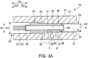
- Figs. 1A to 1C are sectional views each showing a schematic arrangement of a positive-type electromagnetic proportional valve 10.
- Fig. 1A shows a non-excited state where no excitation current flows through a drive portion 13 constituted by a solenoid actuator.
- Fig. 1B shows a state where a relatively small excitation current flows through the drive portion 13 and a spool body 12 is in a neutral position.
- Fig. 1C shows a state where a relatively large excitation current flows through the drive portion 13.
- the electromagnetic proportional valve 10 shown in Figs. 1A to 1C includes a valve body 11, the spool body 12, the drive portion 13, and a biasing portion 14.
- the valve body 11 includes a valve bore 21 extending in the axial direction Dx, and an inlet port 31, an outlet port 32, a drain port 33, and an output port 34 each being open to the valve bore 21.
- the inlet port 31 communicates with an oil pressure source P that supplies a pressure oil
- the outlet port 32 communicates with a discharge portion T to which the pressure oil is discharged.
- the drain port 33 communicates with a drain portion to which the pressure oil is discharged.
- the discharge portion T serves as a drain portion
- the outlet port 32 and the drain port 33 communicate with the common discharge portion (that is, the drain portion).
- the output port 34 communicates with a hydraulic actuator A to which the pressure oil is supplied.
- Specific configuration of the hydraulic actuator A is not limited, and the hydraulic actuator A is typically formed of a hydraulic cylinder or a hydraulic motor.
- the valve bore 21 includes a large-diameter bore portion 22 and a small-diameter bore portion 23, the large-diameter bore portion 22 having a first diameter H1 in the radial direction Dr perpendicular to the axial direction Dx, the small-diameter bore portion 22 having a second diameter H2 smaller than the first diameter H1 in the radial direction Dr.
- the large-diameter bore portion 22 is adjacent to the forward axial direction Dx1 side of the small-diameter bore portion 23.
- One end side of the spool body 12 is positioned in the large-diameter bore portion 22, and the other end side of the spool body 12 is positioned in the small-diameter bore portion 23.
- each of the large-diameter bore portion 22 and the small-diameter bore portion 23 forms a closed space and is filled with the pressure oil supplied from the oil pressure source P.
- the large-diameter bore portion 22 communicates with an outside (in particular, the hydraulic actuator A in the embodiment) via the output port 34 (in particular, the output port 34 open toward the forward axial direction Dx1).
- a drain space 24 enclosed by a small-diameter spool portion 46, a large-diameter spool portion 47, and the valve body 11 has a volume varied in accordance with the position of the spool body 12 in the axial direction Dx, but the drain space 24 communicates with the drain port 33 irrespective of the position of the spool body 12 in the axial direction Dx. Therefore, irrespective of the position of the spool body 12 in the axial direction Dx, the pressure oil in the drain space 24 flows out to the discharge portion T via the drain port 33, and the valve body 11 and the spool body 12 do not receive a pressure from the pressure oil in the drain space 24.
- the spool body 12 is disposed in the valve bore 21 so as to be slidable in the axial direction Dx.
- One end side (the right side in the Figs. 1A to 1C ) of the spool body 12 is positioned in the large-diameter bore portion 22, and the other end side (the left side in the Figs. 1A to 1C ) of the spool body 12 is positioned in the small-diameter bore portion 23.
- the one end side of the spool body 12 positioned in the large-diameter bore portion 22 includes the large-diameter spool portion 47 which has an outer diameter corresponding to the diameter of the large-diameter bore portion 22.
- the other end side of the spool body 12 positioned in the small-diameter bore portion 23 includes the small-diameter spool portion 46 which has an outer diameter corresponding to the diameter of the small-diameter bore portion 23.
- the large-diameter spool portion 47 is adjacent to the forward axial direction Dx1 side of the small-diameter spool portion 46 and is positioned in the large-diameter bore portion 22.
- At least a part of the small-diameter spool portion 46 is positioned in the small-diameter bore portion 23, and a part of the small-diameter spool portion 46 is positioned in the large-diameter bore portion 22 in accordance with the position of the spool body 12 in the axial direction Dx.
- the large-diameter spool portion 47 is in a tight contact with an inner wall surface of the valve body 11 (in particular, an inner wall surface forming the large-diameter bore portion 22) to such a degree as to allow sliding of the spool body 12 in the axial direction Dx.
- the small-diameter spool portion 46 is in a tight contact with the inner wall surface of the valve body 11 (in particular, an inner wall surface forming the small-diameter bore portion 23) to such a degree as to allow sliding of the spool body 12 in the axial direction Dx.
- the pressure oil in the valve bore 21 does not pass between the large-diameter spool portion 47 and the valve body 11 and between the small-diameter spool portion 46 and the valve body 11. Therefore, the pressure oil does not flow from the small-diameter bore portion 23 to the drain space 24, or only a minute amount of pressure oil flows from the small-diameter bore portion 23 to the drain space 24. Likewise, the pressure oil does not flow from the large-diameter bore portion 22 to the drain space 24, or only a minute amount of pressure oil flows from the large-diameter bore portion 22 to the drain space 24.
- the spool body 12 includes a spool bore 41 extending in the axial direction Dx, and a communication hole 42, an outlet hole 43, an inlet hole 44, and an output hole 45 each being open to the spool bore 41.
- the communication hole 42 and the output hole 45 are formed in opposite end portions of the spool body 12, and the outlet hole 43 and the inlet hole 44 are formed in a portion of the spool body 12 between the communication hole 42 and the output hole 45. That is, the output hole 45 is formed in one of one end side and the other end side of the spool body 12 (the large-diameter spool portion 47 side in Figs.
- the communication hole 42 is formed in the other (the small-diameter spool portion 46 side in Figs. 1A to 1C ).
- the outlet hole 43 and the inlet hole 44 are formed in the large-diameter spool portion 47 of the spool body 12, and the outlet hole 43 and the inlet hole 44 are positioned between the communication hole 42 and the output hole 45 with respect to the axial direction Dx.
- the communication hole 42, the outlet hole 43, and the inlet hole 44 are open in the radial direction Dr.
- the communication hole 42 is open to the small-diameter bore portion 23 and thus communicates between the small-diameter bore portion 23 and the spool bore 41 irrespective of the position of the spool body 12 in the axial direction Dx.
- the outlet hole 43 is open toward the outlet port 32 or the inner wall surface of the valve body 11 (in particular, the inner wall surface forming the large-diameter bore portion 22), and the inlet hole 44 is open toward the inlet port 31 or the inner wall surface of the valve body 11 (in particular, the inner wall surface forming the large-diameter bore portion 22).
- the output hole 45 is open in the axial direction Dx (the forward axial direction Dx1 in Figs. 1A to 1C ) and communicates with the output port 34 via the valve bore 21 (in particular, the large-diameter bore portion 22).
- the large-diameter bore portion 22 connected to the hydraulic actuator A via the output port 34 communicates with the spool bore 41 via one of the communication hole 42 and the output hole 45 (via the output hole 45 in Figs. 1A to 1C ).
- the small-diameter bore portion 23 communicates with the spool bore 41 via the other of the communication hole 42 and the output hole 45 (via the communication hole 42 in Figs. 1A to 1C ).
- the large-diameter bore portion 22 and the small-diameter bore portion 23 in the valve bore 21 communicate with each other via the spool bore 41, the communication hole 42, and the output hole 45, and therefore, the pressure of the pressure oil in the large-diameter bore portion 22, the pressure of the pressure oil in the small-diameter bore portion 23, and the pressure of the pressure oil in the valve bore 21 are equal.
- the drive portion 13 presses the spool body 12 in the forward direction Dx1 of the axial direction Dx (hereinafter also referred to as "the forward axial direction Dx1"), and a pressing force for pressing the spool body 12 varies in accordance with the applied electric current (that is, the excitation current).
- the drive portion 13 of the embodiment is formed of a solenoid actuator including an electromagnet (not shown) and a plunger 51 combined together.
- the specific configuration of the solenoid actuator is not limited, and the drive portion 13 may be formed of any solenoid actuator in which the pressing force applied to the spool body 12 by the plunger 51 is determined in accordance with the magnitude of the excitation current.
- the biasing portion 14 biases the spool body 12 (the large-diameter spool portion 47 in the embodiment) toward the reverse direction Dx2 (hereinafter also referred to as "the reverse axial direction Dx2") opposite to the forward direction Dx1 of the axial direction Dx.
- the force applied to the spool body 12 by the biasing portion 14 varies in accordance with the position of the spool body 12 in the axial direction Dx, and as the spool body 12 moves toward the forward axial direction Dx1 side, the force applied to the spool body 12 by the biasing portion 14 is larger.
- the biasing portion 14 may be formed of an elastic member, such as, typically, a coil spring.
- a coil spring is made of a linear material (wire) wound spirally.
- one of the one end side and the other end side of the spool body 12 (the small-diameter spool portion 46 side in Figs. 1A to 1C ) is pressed by the plunger 51 of the drive portion 13, and the drive portion 13 applies a force to the spool body 12 in the forward axial direction Dx1.
- the other of the one end side and the other end side of the spool body 12 (the large-diameter spool portion 47 side in Figs. 1A to 1C ) has the output hole 45 formed therein and is biased by the biasing portion 14, and the biasing portion 14 applies a force to the spool body 12 in the reverse axial direction Dx2.
- the positive-type electromagnetic proportional valve 10 configured as described above has difference between pressure-receiving areas on the opposite sides of the spool body 12. With a balance between the hydraulic pressure produced by the difference between pressure-receiving areas, the thrust of the drive portion 13, and the biasing force of the biasing portion 14, the pressure oil having a desired pressure can be supplied from the output hole 45 to the hydraulic actuator A.
- the surface area of the spool body 12 that receives a force from the pressure oil filled in the valve bore 21 and the spool bore 41 in the forward axial direction Dx1 is different from the surface area of the spool body 12 that receives a force from the pressure oil in the reverse axial direction Dx2. More specifically, the surface area of the spool body 12 that receives a force from the pressure oil in the reverse axial direction Dx2 is larger than the surface area of the spool body 12 that receives a force from the pressure oil in the forward axial direction Dx1.
- the force F1 (the hydraulic pressure) imparted to the spool body 12 by the pressure oil in the forward axial direction Dx1 is different from the force F2 imparted to the spool body 12 by the pressure oil in the reverse axial direction Dx2.
- the relationship F1 ⁇ F2 is satisfied.
- the spool body 12 receives the force in the reverse axial direction Dx2 from the pressure oil filled in the valve bore 21 and the spool bore 41.
- the spool body 12 further receives a force from the plunger 51 of the drive portion 13 and the biasing portion 14.
- Ph the pressure of the pressure oil in the valve bore 21 and the spool bore 41
- Fd representing the force imparted to the spool body 12 by the drive portion 13 in the forward axial direction Dx1
- Fsp representing the force imparted to the spool body 12 by the biasing portion 14 in the reverse axial direction Dx2
- the value of Up is basically constant.
- the value of Fsp is within a certain range. Therefore, as is obvious from Expression 1 above, the pressure Ph of the pressure oil in the valve bore 21 and the spool bore 41 increases with the increase of the force Fd imparted to the spool body 12 by the drive portion 13.
- a control unit controls the excitation current applied to the drive portion 13 to adjust the force (Fd) imparted to the spool body 12 by the drive portion 13, such that the pressure oil having a desired pressure can be supplied to the hydraulic actuator A from the output hole 45 via the large-diameter portion 22 and the output port 34.
- the spool body 12 When no electric current is applied to the drive portion 13 or a first electric current is applied to the drive portion 13, the spool body 12 is positioned at a first slide position shown in Fig. 1A . At this time, the spool bore 41 communicates with the outlet port 32 via the outlet hole 43, and the pressure oil in the spool bore 41 and the pressure oil in the valve bore 21 have a decreased pressure.
- the spool body 12 When a second electric current larger than the first electric current is applied to the drive portion 13, the spool body 12 is pressed by the plunger 51 of the drive portion 13 in the forward axial direction Dx1 and moved into a second slide position shown in Fig. 1C .
- the spool bore 41 communicates with the inlet port 31 via the inlet hole 44, and the pressure oil from the oil pressure source P is supplied to the spool bore 41. Therefore, the pressure oil in the spool bore 41 and the pressure oil in the valve bore 21 have an increased pressure.
- the spool body 12 positioned in the first slide position (see Fig. 1A ) is positioned on the reverse axial direction Dx2 side of the spool body 12 positioned in the second slide position (see Fig. 1C ).
- the spool body 12 When a third electric current larger than the first electric current and smaller than the second electric current is applied to the drive portion 13, the spool body 12 is positioned in a third slide position (a neutral position) shown in Fig. 1B . At this time, the outlet hole 43 does not communicate with the outlet port 32, and the inlet hole 44 does not communicate with the inlet port 31. Thus, the spool bore 41 is disconnected from the inlet port 31 and the outlet port 32, and the pressure of the pressure oil in the spool bore 41 and the pressure oil in the valve bore 21 is basically maintained without a decrease or an increase thereof.
- the pressure oil having a desired pressure is supplied from the output hole 45 in accordance with the following mechanism.
- the control unit applies the excitation current preset for the desired pressure of the pressure oil to the drive portion 13.
- the plunger 51 of the drive portion 13 presses the spool body 12 in the forward axial direction Dx1 and positions the spool body 12 into the second slide position (see Fig. 1C ), such that the outlet hole 43 is disconnected from the outlet port 32 and the inlet hole 43 communicates with the inlet port 31.
- the pressure oil is supplied from the oil pressure source P to the spool bore 41 and the valve bore 21, such that the pressure of the pressure oil in the spool bore 41 and the valve bore 21 is increased.
- the spool body 12 When the pressure of the pressure oil in the spool bore 41 and the valve bore 21 exceeds the desired pressure while the magnitude of the excitation current applied to the drive portion 13 is maintained, the spool body 12 is slid in the reverse axial direction Dx2 and positioned into the first slide position (see Fig. 1A ). Thus, the inlet hole 44 is disconnected from the inlet port 31 and the outlet hole 43 communicates with the outlet port 32, and the pressure of the pressure oil in the spool bore 41 and the valve bore 21 is decreased.
- the spool body 12 repeatedly moves between the second slide position (see Fig. 1C ) and the first slide position (see Fig. 1A ) while the excitation current preset for the desired pressure of the pressure oil is continuously applied to the drive portion 13, such that the pressure oil is repeatedly supplied to and discharged from the spool bore 41.
- the pressure of the pressure oil in the spool bore 41 and the valve bore 21 is maintained at the desired value, and the pressure oil having the desired pressure flows through the output hole 45 to the hydraulic actuator A.
- the excitation current applied to the drive portion 13 is controlled to adjust the degrees of opening of the valve bore 21 and the spool bore 41 to the oil pressure source P and the discharge portion T, such that the pressure oil having the desired pressure can be supplied from the output hole 45 to the hydraulic actuator A.
- the spool body 12 is positioned in the first slide position (see Fig. 1A ), and the pressure oil in the spool bore 41 and the valve bore 21 is discharged to the discharge portion T via the outlet hole 43 and the outlet port 32.
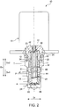
- Fig. 2 shows a specific example of the positive-type electromagnetic proportional valve 10 according to an embodiment of the present invention.
- the electromagnetic proportional valve 10 is partially shown in a sectional view.
- the spool body 12 is horizontally symmetric with respect to the axial direction Dx, the left and right halves of the spool body 12 of Fig. 2 are shown in different states. More specifically, the left half of the spool body 12 of Fig. 2 is shown in the state where the spool body 12 is positioned in the neutral position (see Fig. 1B ). On the other hand, the right half of the spool body 12 of Fig. 2 is shown in the state where the spool body 12 is positioned in the first slide position (see Fig. 1A ) in which the inlet port 31 is disconnected from the inlet hole 44 and the outlet hole 43 communicates with the outlet port 32.
- the electromagnetic proportional valve 10 of Fig. 2 can enter the state where the spool body 12 is positioned in the second slide position (see Fig. 1C ) in which the inlet port 31 communicates with the inlet hole 44 and the outlet hole 43 is disconnected from the outlet port 32.
- the electromagnetic proportional valve 10 of Fig. 2 has basically the same configuration as the electromagnetic proportional valve 10 shown in Figs. 1A to 1C and exhibits the same behavior as the electromagnetic proportional valve 10 shown in Figs. 1A to 1C .
- the communication hole 42 of the electromagnetic proportional valve 10 shown in Figs. 1A to 1C is open in the radial direction Dr
- the communication hole 42 of the electromagnetic proportional valve 10 shown in Fig. 2 is open in the axial direction Dx (in particular, the reverse axial direction Dx2).
- the output port 34 of the electromagnetic proportional valve 10 shown in Figs. 1A to 1C is open in the axial direction Dx (in particular, the forward axial direction Dx1)
- the output port 34 of the electromagnetic proportional valve 10 shown in Fig. 2 is open in the radial direction Dr, and therefore, the pressure oil from the output hole 45 is moved in the radial direction Dr via the large-diameter bore portion 22 and the output port 34 and supplied to the hydraulic actuator A.
- the large-diameter bore portion 22 and the small-diameter bore portion 23 communicate with each other via the spool bore 41, the communication hole 42, and the output hole 45, and therefore, the pressure of the pressure oil in the large-diameter bore portion 22, the pressure of the pressure oil in the small-diameter bore portion 23, and the pressure of the pressure oil in the spool bore 41 are equal.
- the force substantially imparted to the spool body 12 by the pressure oil is a function of the difference Up between the surface area S1 of the spool body 12 that receives a force from the pressure oil in the valve bore 21 and the spool bore 41 (specifically, the small-diameter bore portion 23) in the forward axial direction Dx1 and the surface area S2 of the spool body 12 that receives a force from the pressure oil in the valve bore 21 and the spool bore 41 (specifically, the large-diameter bore portion 22 and the spool bore 41) in the reverse axial direction Dx2.
- the substantial increase of the force imparted to the spool body 12 by the pressure oil is moderate as compared to the increase of the pressure of the pressure oil supplied from the output hole 45, and thus a drive portion 13 (a solenoid actuator in the embodiment) having a small size can be used to produce a high oil pressure output.
- the output hole 45 is formed in an end portion of the spool body 12, and the output port 34 is formed in an end portion of the valve body 11. This increases the degree of freedom in arrangement of the output hole 45 and the output port 34. For example, it is possible that each of the output hole 45 and the output port 34 is open in both the axial direction Dx and the radial direction Dr.
- the spool body 12 when the output hole 45 is open in the axial direction Dx, the spool body 12 can have a small axial length.
- the valve body 11 when the output port 34 is open in the axial direction Dx, the valve body 11 can have a small axial length.
- the electromagnetic proportional valve 10 as a whole can be compact.
- the opening directions of the output hole 45 and the output port 34 can be adjusted in accordance with the specific position of the hydraulic actuator A relative to the electromagnetic proportional valve 10, such that the hydraulic actuator A can be positioned in various positions relative to the electromagnetic proportional valve 10. This is also favorable for device layout.
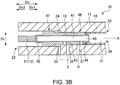
- Figs. 3A to 3C are sectional views showing a schematic arrangement of a negative-type electromagnetic proportional valve 10.
- Fig. 3A shows a non-excited state where no excitation current flows through the drive portion 13
- Fig. 3B shows a state where the spool body 12 is in the neutral state
- Fig. 3C shows a state where a relatively large excitation current flows through the drive portion 13.
- the small-diameter bore portion 23 of the valve bore 21 is adjacent to the forward axial direction Dx1 side of the large-diameter bore portion 22.
- each of the large-diameter bore portion 22 and the small-diameter bore portion 23 forms a closed space and is filled with the pressure oil supplied from the oil pressure source P.
- the small-diameter bore portion 23 communicates with an outside (in particular, the hydraulic actuator A in the embodiment) via the output port 34 (in particular, the output port 34 open toward the forward axial direction Dx1).
- One end side (the left side in the Figs. 3A to 3C ) of the spool body 12 is positioned in the large-diameter bore portion 22, and the other end side (the right side in the Figs. 3A to 3C ) of the spool body 12 is positioned in the small-diameter bore portion 23.
- the one end side of the spool body 12 positioned in the large-diameter bore portion 22 includes the large-diameter spool portion 47 which has an outer diameter corresponding to the diameter of the large-diameter bore portion 22.
- the other end side of the spool body 12 positioned in the small-diameter bore portion 23 includes the small-diameter spool portion 46 which has an outer diameter corresponding to the diameter of the small-diameter bore portion 23.
- the large-diameter spool portion 47 is adjacent to the reverse axial direction Dx2 side of the small-diameter spool portion 46 and is positioned in the large-diameter bore portion 22.
- At least a part of the small-diameter spool portion 46 is positioned in the small-diameter bore portion 23, and a part of the small-diameter spool portion 46 is positioned in the large-diameter bore portion 22 in accordance with the position of the spool body 12 in the axial direction Dx.
- the output hole 45 is formed in one of one end side and the other end side of the spool body 12 (the small-diameter spool portion 46 side in Figs. 3A to 3C ), and the communication hole 42 is formed in the other (the large-diameter spool portion 47 side in Figs. 3A to 3C ).
- the outlet hole 43 and the inlet hole 44 are formed in the small-diameter spool portion 46 of the spool body 12.
- the communication hole 42 is open to the large-diameter bore portion 22 and thus communicates between the large-diameter bore portion 22 and the spool bore 41 irrespective of the position of the spool body 12 in the axial direction Dx.
- the outlet hole 43 is open toward the outlet port 32 or the inner wall surface of the valve body 11 (in particular, the inner wall surface forming the small-diameter bore portion 23)
- the inlet hole 44 is open toward the inlet port 31 or the inner wall surface of the valve body 11 (in particular, the inner wall surface forming the small-diameter bore portion 23).
- the output hole 45 is open in the axial direction Dx (the forward axial direction Dx1 in Figs. 3A to 3C ) and communicates with the output port 34 via the valve bore 21 (in particular, the small-diameter bore portion 23).
- the small-diameter bore portion 23 connected to the hydraulic actuator A via the output port 34 communicates with the spool bore 41 via one of the communication hole 42 and the output hole 45 (via the output hole 45 in Figs. 3A to 3C ).
- the large-diameter bore portion 22 communicates with the spool bore 41 via the other of the communication hole 42 and the output hole 45 (via the communication hole 42 in Figs. 3A to 3C ).
- the large-diameter bore portion 22 and the small-diameter bore portion 23 communicate with each other via the spool bore 41, the communication hole 42, and the output hole 45, and therefore, the pressure of the pressure oil in the large-diameter bore portion 22, the pressure of the pressure oil in the small-diameter bore portion 23, and the pressure of the pressure oil in the spool bore 41 are equal.
- the drive portion 13 presses the spool body 12 in the forward axial direction Dx1, and a pressing force for pressing the spool body 12 varies in accordance with the excitation current.
- the biasing portion 14 biases the spool body 12 (the small-diameter spool portion 46 in the embodiment) toward the reverse axial direction Dx2. In this way, one of the one end side and the other end side of the spool body 12 (the large-diameter spool portion 47 side in Figs. 3A to 3C ) is pressed by the plunger 51 of the drive portion 13, and the drive portion 13 applies a force to the spool body 12 in the forward axial direction Dx1.
- the other of the one end side and the other end side of the spool body 12 (the small-diameter spool portion 46 side in Figs. 3A to 3C ) has the output hole 45 formed therein and is biased by the biasing portion 14, and the biasing portion 14 applies a force to the spool body 12 in the reverse axial direction Dx2.
- the negative-type electromagnetic proportional valve 10 described above also has difference between pressure-receiving areas on the opposite sides of the spool body 12. With a balance between the hydraulic pressure produced by the difference between pressure-receiving areas, the thrust of the drive portion 13, and the biasing force of the biasing portion 14, the pressure oil having a desired pressure can be supplied from the output hole 45 to the hydraulic actuator A.
- the surface area of the spool body 12 that receives a force from the pressure oil filled in the valve bore 21 and the spool bore 41 in the forward axial direction Dx1 is different from the surface area of the spool body 12 that receives a force from the pressure oil in the reverse axial direction Dx2. More specifically, the surface area of the spool body 12 that receives a force from the pressure oil in the forward axial direction Dx1 is larger than the surface area of the spool body 12 that receives a force from the pressure oil in the reverse axial direction Dx2.
- the force F1 imparted to the spool body 12 by the pressure oil in the forward axial direction Dx1 is different from the force F2 imparted to the spool body 12 by the pressure oil in the reverse axial direction Dx2.
- the relationship F1 > F2 is satisfied.
- the spool body 12 receives the force in the forward axial direction Dx1 from the pressure oil filled in the valve bore 21 and the spool bore 41.
- the value of Un is basically constant.
- the value of Fsp is within a certain range. Therefore, as is obvious from Expression 2 above, the pressure Ph of the pressure oil in the valve bore 21 and the spool bore 41 decreases with the increase of the force Fd imparted to the spool body 12 by the drive portion 13.
- a control unit controls the excitation current applied to the drive portion 13 to adjust the force (Fd) imparted to the spool body 12 by the drive portion 13, such that the pressure oil having a desired pressure can be supplied to the hydraulic actuator A from the output hole 45 via the small-diameter portion 23 and the output port 34.
- the spool body 12 When no electric current is applied to the drive portion 13 or a first electric current is applied to the drive portion 13, the spool body 12 is positioned at a first slide position shown in Fig. 3A . At this time, the spool bore 41 communicates with the inlet port 31 via the inlet hole 44, and the pressure oil in the spool bore 41 and the pressure oil in the valve bore 21 have an increased pressure.
- the spool body 12 When a second electric current larger than the first electric current is applied to the drive portion 13, the spool body 12 is pressed by the plunger 51 of the drive portion 13 in the forward axial direction Dx1 and moved into a second slide position shown in Fig. 3C . At this time, the spool bore 41 communicates with the outlet port 32 via the outlet hole 43, and the pressure oil in the spool bore 41 and the pressure oil in the valve bore 21 have a decreased pressure.
- the spool body 12 positioned in the first slide position (see Fig. 3A ) is positioned on the reverse axial direction Dx2 side of the spool body 12 positioned in the second slide position (see Fig. 3C ).
- the spool body 12 When a third electric current larger than the first electric current and smaller than the second electric current is applied to the drive portion 13, the spool body 12 is positioned in a third slide position shown in Fig. 3B . At this time, the outlet hole 43 does not communicate with the outlet port 32, and the inlet hole 44 does not communicate with the inlet port 31, and therefore, the pressure of the pressure oil in the spool bore 41 and the pressure oil in the valve bore 21 is basically maintained without a decrease or an increase thereof.
- the pressure oil having a desired pressure is supplied from the output hole 45 in accordance with the following mechanism.
- the excitation current preset for the desired pressure of the pressure oil is applied to the drive portion 13.
- the plunger 51 of the drive portion 13 presses the spool body 12 in the forward axial direction Dx1 and positions the spool body 12 into the second slide position (see Fig. 3C ), such that the inlet hole 44 is disconnected from the inlet port 31 and the outlet hole 43 communicates with the outlet port 32.
- the pressure of the pressure oil in the spool bore 41 and the valve bore 21 is decreased.
- the spool body 12 When the pressure of the pressure oil in the spool bore 41 and the valve bore 21 falls below the desired pressure while the magnitude of the excitation current applied to the drive portion 13 is maintained, the spool body 12 is slid in the reverse axial direction Dx2 and positioned into the first slide position (see Fig. 3A ). Thus, the outlet hole 43 is disconnected from the outlet port 32 and the inlet hole 44 communicates with the inlet port 31, the pressure oil from the oil pressure source P is supplied to the spool bore 41 and the valve bore 21, and the pressure of the pressure oil in the spool bore 41 and the valve bore 21 is increased.
- the spool body 12 repeatedly moves between the second slide position (see Fig. 3C ) and the first slide position (see Fig. 3A ) while the excitation current preset for the desired pressure of the pressure oil is continuously applied to the drive portion 13, such that the pressure oil is repeatedly supplied to and discharged from the spool bore 41.
- the pressure of the pressure oil in the spool bore 41 and the valve bore 21 is maintained at the desired value, and the pressure oil having the desired pressure flows through the output hole 45 to the hydraulic actuator A.
- the spool body 12 When no excitation current is applied to the drive portion 13 and the pressure oil in the spool bore 41 and the valve bore 21 has a high pressure, the spool body 12 is positioned in the first slide position (see Fig. 3A ), and the pressure oil from the oil pressure source P is supplied to the spool bore 41 and the valve bore 21 via the inlet hole 44 and the inlet port 31.
- Fig. 4 shows a specific example of the negative-type electromagnetic proportional valve 10 according to an embodiment of the present invention.
- the electromagnetic proportional valve 10 is partially shown in a sectional view.
- the spool body 12 is horizontally symmetric with respect to the axial direction Dx, the left and right halves of the spool body 12 of Fig. 4 are shown in different states. More specifically, the left half of the spool body 12 of Fig. 2 is shown in the state where the spool body 12 is positioned in the neutral position (see Fig. 3B ). On the other hand, the right half of the spool body 12 of Fig. 2 is shown in the state where the spool body 12 is positioned in the first slide position (see Fig. 3A ) in which the inlet port 31 communicates with the inlet hole 44 and the outlet hole 43 is disconnected from the outlet port 32.
- the electromagnetic proportional valve 10 of Fig. 4 can enter the state where the spool body 12 is positioned in the second slide position (see Fig. 3C ) in which the inlet port 31 is disconnected from the inlet hole 44 and the outlet hole 43 communicates with the outlet port 32.
- the electromagnetic proportional valve 10 of Fig. 4 has basically the same configuration as the electromagnetic proportional valve 10 shown in Figs. 3A to 3C and exhibits the same behavior as the electromagnetic proportional valve 10 shown in Figs. 3A to 3C .
- the communication hole 42 of the electromagnetic proportional valve 10 shown in Figs. 3A to 3C is open in the radial direction Dr
- the communication hole 42 of the electromagnetic proportional valve 10 shown in Fig. 4 is open in the axial direction Dx (in particular, the reverse axial direction Dx2).
- the output port 34 of the electromagnetic proportional valve 10 shown in Figs. 3A to 3C is open in the axial direction Dx (in particular, the forward axial direction Dx1)
- the output port 34 of the electromagnetic proportional valve 10 shown in Fig. 4 is open in the radial direction Dr, and therefore, the pressure oil from the output hole 45 is moved in the radial direction Dr via the large-diameter bore portion 22 and the output port 34 and supplied to the hydraulic actuator A.
- the pressure of the pressure oil in the large-diameter bore portion 22, the pressure of the pressure oil in the small-diameter bore portion 23, and the pressure of the pressure oil in the spool bore 41 are equal.
- the force substantially imparted to the spool body 12 by the pressure oil is a function of the difference Un between the surface area S1 of the spool body 12 that receives a force from the pressure oil in the valve bore 21 and the spool bore 41 (specifically, the large-diameter bore portion 22) in the forward axial direction Dx1 and the surface area S2 of the spool body 12 that receives a force from the pressure oil in the valve bore 21 and the spool bore 41 (specifically, the small-diameter bore portion 23 and the spool bore 41) in the reverse axial direction Dx2.
- the substantial increase of the force imparted to the spool body 12 by the pressure oil is moderate as compared to the increase of the pressure of the pressure oil supplied from the output hole 45, and thus a drive portion 13 having a small size can be used to produce a high oil pressure output.
- the output hole 45 is formed in an end portion of the spool body 12, and the output port 34 is formed in an end portion of the valve body 11. This increases the degree of freedom in arrangement of the output hole 45 and the output port 34.
- the spool body 12 can have a small axial length
- the valve body 11 can have a small axial length.
- the electromagnetic proportional valve 10 as a whole can be compact. This is also favorable for device layout.
- the invention is not limited to the above-described embodiments and variations. For example, various modifications may be made to the elements of the embodiments and the variations described above.
- the invention also encompasses embodiments including components other than the above-described components.
- the invention also encompasses embodiments not including some elements of the above-described components.
- the invention also encompasses embodiments including some of the components included in an embodiment of the invention and some of the components included in another embodiment of the invention. Accordingly, components included in the above-described embodiments and variations may be combined with components included in embodiments other than those described above, and the invention encompasses embodiments including such combinations.
- the invention produces not only the advantageous effects described above but also specific effects in accordance with specific configuration of the embodiments.
- addition, modification, and partial deletion of the elements recited in the claims or described in the specification, the abstract, and the drawings can be made variously within the technical idea and the purport of the present invention.
Landscapes
- Engineering & Computer Science (AREA)
- General Engineering & Computer Science (AREA)
- Mechanical Engineering (AREA)
- Physics & Mathematics (AREA)
- General Physics & Mathematics (AREA)
- Automation & Control Theory (AREA)
- Magnetically Actuated Valves (AREA)
- Multiple-Way Valves (AREA)
Applications Claiming Priority (2)
| Application Number | Priority Date | Filing Date | Title |
|---|---|---|---|
| JP2017061439 | 2017-03-27 | ||
| PCT/JP2018/009207 WO2018180367A1 (fr) | 2017-03-27 | 2018-03-09 | Soupape proportionnelle électromagnétique |
Publications (3)
| Publication Number | Publication Date |
|---|---|
| EP3604875A1 true EP3604875A1 (fr) | 2020-02-05 |
| EP3604875A4 EP3604875A4 (fr) | 2020-03-25 |
| EP3604875B1 EP3604875B1 (fr) | 2024-11-27 |
Family
ID=63675352
Family Applications (1)
| Application Number | Title | Priority Date | Filing Date |
|---|---|---|---|
| EP18777935.0A Active EP3604875B1 (fr) | 2017-03-27 | 2018-03-09 | Soupape proportionnelle électromagnétique |
Country Status (5)
| Country | Link |
|---|---|
| EP (1) | EP3604875B1 (fr) |
| JP (1) | JP7065828B2 (fr) |
| KR (1) | KR102530260B1 (fr) |
| CN (1) | CN110337555B (fr) |
| WO (1) | WO2018180367A1 (fr) |
Cited By (1)
| Publication number | Priority date | Publication date | Assignee | Title |
|---|---|---|---|---|
| DE102021214013A1 (de) | 2021-12-09 | 2023-06-15 | Zf Friedrichshafen Ag | Wegeventil für ein Getriebe eines Kraftfahrzeugs |
Families Citing this family (3)
| Publication number | Priority date | Publication date | Assignee | Title |
|---|---|---|---|---|
| JP7186584B2 (ja) * | 2018-11-21 | 2022-12-09 | ナブテスコ株式会社 | 電磁弁、方向切換弁及び建設機械 |
| JP7369519B2 (ja) * | 2018-12-10 | 2023-10-26 | ナブテスコ株式会社 | 電磁比例弁及び方向切換弁 |
| JP7325192B2 (ja) * | 2019-02-14 | 2023-08-14 | ナブテスコ株式会社 | 電磁弁及び作業機械 |
Family Cites Families (10)
| Publication number | Priority date | Publication date | Assignee | Title |
|---|---|---|---|---|
| JPS5650208Y2 (fr) * | 1976-09-08 | 1981-11-24 | ||
| JPS6085676U (ja) * | 1983-11-14 | 1985-06-13 | 株式会社小松製作所 | 電磁比例圧力制御弁 |
| JPH02163583A (ja) | 1988-12-19 | 1990-06-22 | Komatsu Ltd | 電磁比例圧力制御弁 |
| US7325564B2 (en) * | 2004-03-24 | 2008-02-05 | Keihin Corporation | Linear solenoid valve |
| CN1295441C (zh) * | 2004-11-05 | 2007-01-17 | 宁波华液机器制造有限公司 | 一种比例压差控制阀 |
| WO2011124395A1 (fr) * | 2010-04-10 | 2011-10-13 | Hydac Fluidtechnik Gmbh | Régulateur de débit |
| US8607823B2 (en) * | 2010-07-13 | 2013-12-17 | Delphi Technologies, Inc. | Pressure control valve |
| DE102013008840A1 (de) * | 2013-05-24 | 2014-11-27 | Hydac Fluidtechnik Gmbh | Proportional-Druckregelventil |
| TWI535960B (zh) * | 2013-07-01 | 2016-06-01 | Winner Hydraulics Corp | Regulator valve |
| JP6656831B2 (ja) * | 2015-07-08 | 2020-03-04 | ナブテスコ株式会社 | 電磁比例弁 |
-
2018
- 2018-03-09 CN CN201880014359.0A patent/CN110337555B/zh active Active
- 2018-03-09 EP EP18777935.0A patent/EP3604875B1/fr active Active
- 2018-03-09 WO PCT/JP2018/009207 patent/WO2018180367A1/fr not_active Ceased
- 2018-03-09 JP JP2019509156A patent/JP7065828B2/ja active Active
- 2018-03-09 KR KR1020197028247A patent/KR102530260B1/ko active Active
Cited By (1)
| Publication number | Priority date | Publication date | Assignee | Title |
|---|---|---|---|---|
| DE102021214013A1 (de) | 2021-12-09 | 2023-06-15 | Zf Friedrichshafen Ag | Wegeventil für ein Getriebe eines Kraftfahrzeugs |
Also Published As
| Publication number | Publication date |
|---|---|
| KR20190127763A (ko) | 2019-11-13 |
| CN110337555A (zh) | 2019-10-15 |
| KR102530260B1 (ko) | 2023-05-09 |
| EP3604875B1 (fr) | 2024-11-27 |
| JPWO2018180367A1 (ja) | 2020-02-06 |
| JP7065828B2 (ja) | 2022-05-12 |
| CN110337555B (zh) | 2022-02-25 |
| WO2018180367A1 (fr) | 2018-10-04 |
| EP3604875A4 (fr) | 2020-03-25 |
Similar Documents
| Publication | Publication Date | Title |
|---|---|---|
| EP3604875B1 (fr) | Soupape proportionnelle électromagnétique | |
| US8991428B2 (en) | Die cast sleeve with stability enhancement features occupying a small package space | |
| US8960233B2 (en) | Solenoid valve | |
| KR20170076739A (ko) | 용량 제어 밸브 | |
| US9334978B2 (en) | Valve device for a hydraulic circuit, and oil-pump regulating arrangement | |
| US20070267077A1 (en) | Fluid pressure control apparatus | |
| JP2008286381A (ja) | 電磁弁 | |
| US10018269B2 (en) | Normally high acting linear force solenoid | |
| KR20180020145A (ko) | 밸브, 특히 비례 압력 조절 밸브 | |
| JP2004324740A (ja) | 比例電磁弁及びその制御方法 | |
| JP3955580B2 (ja) | バルブ装置、特に比例制御バルブ兼方向制御バルブ | |
| JP5391037B2 (ja) | 電磁弁装置 | |
| CN111212996B (zh) | 带电磁比例阀的盖 | |
| US20200025286A1 (en) | Hydraulic control device for automatic transmission | |
| JP2013087807A (ja) | スプール制御弁 | |
| JP7325192B2 (ja) | 電磁弁及び作業機械 | |
| JP2007100829A (ja) | バルブ装置 | |
| JP2018146038A (ja) | 電磁式減圧弁及び電磁式減圧弁を備える流体圧制御装置 | |
| JP5998109B2 (ja) | 液圧回転機の容量制御装置 | |
| JP3890593B2 (ja) | スプール弁装置 | |
| JP2020051499A (ja) | 流量制御弁 | |
| JPH04205009A (ja) | 圧力制御電磁スプール弁 |
Legal Events
| Date | Code | Title | Description |
|---|---|---|---|
| STAA | Information on the status of an ep patent application or granted ep patent |
Free format text: STATUS: THE INTERNATIONAL PUBLICATION HAS BEEN MADE |
|
| PUAI | Public reference made under article 153(3) epc to a published international application that has entered the european phase |
Free format text: ORIGINAL CODE: 0009012 |
|
| STAA | Information on the status of an ep patent application or granted ep patent |
Free format text: STATUS: REQUEST FOR EXAMINATION WAS MADE |
|
| 17P | Request for examination filed |
Effective date: 20190926 |
|
| AK | Designated contracting states |
Kind code of ref document: A1 Designated state(s): AL AT BE BG CH CY CZ DE DK EE ES FI FR GB GR HR HU IE IS IT LI LT LU LV MC MK MT NL NO PL PT RO RS SE SI SK SM TR |
|
| AX | Request for extension of the european patent |
Extension state: BA ME |
|
| A4 | Supplementary search report drawn up and despatched |
Effective date: 20200220 |
|
| RIC1 | Information provided on ipc code assigned before grant |
Ipc: F16K 3/26 20060101ALI20200215BHEP Ipc: G05D 7/06 20060101ALI20200215BHEP Ipc: F16K 39/04 20060101ALI20200215BHEP Ipc: F16K 11/07 20060101ALI20200215BHEP Ipc: F16K 31/06 20060101ALI20200215BHEP Ipc: F16K 11/065 20060101AFI20200215BHEP |
|
| DAV | Request for validation of the european patent (deleted) | ||
| DAX | Request for extension of the european patent (deleted) | ||
| STAA | Information on the status of an ep patent application or granted ep patent |
Free format text: STATUS: EXAMINATION IS IN PROGRESS |
|
| 17Q | First examination report despatched |
Effective date: 20201124 |
|
| P01 | Opt-out of the competence of the unified patent court (upc) registered |
Effective date: 20230523 |
|
| GRAP | Despatch of communication of intention to grant a patent |
Free format text: ORIGINAL CODE: EPIDOSNIGR1 |
|
| STAA | Information on the status of an ep patent application or granted ep patent |
Free format text: STATUS: GRANT OF PATENT IS INTENDED |
|
| INTG | Intention to grant announced |
Effective date: 20240719 |
|
| GRAS | Grant fee paid |
Free format text: ORIGINAL CODE: EPIDOSNIGR3 |
|
| GRAA | (expected) grant |
Free format text: ORIGINAL CODE: 0009210 |
|
| STAA | Information on the status of an ep patent application or granted ep patent |
Free format text: STATUS: THE PATENT HAS BEEN GRANTED |
|
| AK | Designated contracting states |
Kind code of ref document: B1 Designated state(s): AL AT BE BG CH CY CZ DE DK EE ES FI FR GB GR HR HU IE IS IT LI LT LU LV MC MK MT NL NO PL PT RO RS SE SI SK SM TR |
|
| REG | Reference to a national code |
Ref country code: GB Ref legal event code: FG4D |
|
| REG | Reference to a national code |
Ref country code: CH Ref legal event code: EP |
|
| REG | Reference to a national code |
Ref country code: DE Ref legal event code: R096 Ref document number: 602018077006 Country of ref document: DE |
|
| REG | Reference to a national code |
Ref country code: IE Ref legal event code: FG4D |
|
| REG | Reference to a national code |
Ref country code: LT Ref legal event code: MG9D |
|
| REG | Reference to a national code |
Ref country code: NL Ref legal event code: MP Effective date: 20241127 |
|
| PG25 | Lapsed in a contracting state [announced via postgrant information from national office to epo] |
Ref country code: HR Free format text: LAPSE BECAUSE OF FAILURE TO SUBMIT A TRANSLATION OF THE DESCRIPTION OR TO PAY THE FEE WITHIN THE PRESCRIBED TIME-LIMIT Effective date: 20241127 Ref country code: PT Free format text: LAPSE BECAUSE OF FAILURE TO SUBMIT A TRANSLATION OF THE DESCRIPTION OR TO PAY THE FEE WITHIN THE PRESCRIBED TIME-LIMIT Effective date: 20250327 Ref country code: IS Free format text: LAPSE BECAUSE OF FAILURE TO SUBMIT A TRANSLATION OF THE DESCRIPTION OR TO PAY THE FEE WITHIN THE PRESCRIBED TIME-LIMIT Effective date: 20250327 |
|
| PG25 | Lapsed in a contracting state [announced via postgrant information from national office to epo] |
Ref country code: NL Free format text: LAPSE BECAUSE OF FAILURE TO SUBMIT A TRANSLATION OF THE DESCRIPTION OR TO PAY THE FEE WITHIN THE PRESCRIBED TIME-LIMIT Effective date: 20241127 Ref country code: FI Free format text: LAPSE BECAUSE OF FAILURE TO SUBMIT A TRANSLATION OF THE DESCRIPTION OR TO PAY THE FEE WITHIN THE PRESCRIBED TIME-LIMIT Effective date: 20241127 |
|
| REG | Reference to a national code |
Ref country code: AT Ref legal event code: MK05 Ref document number: 1746004 Country of ref document: AT Kind code of ref document: T Effective date: 20241127 |
|
| PG25 | Lapsed in a contracting state [announced via postgrant information from national office to epo] |
Ref country code: BG Free format text: LAPSE BECAUSE OF FAILURE TO SUBMIT A TRANSLATION OF THE DESCRIPTION OR TO PAY THE FEE WITHIN THE PRESCRIBED TIME-LIMIT Effective date: 20241127 |
|
| PG25 | Lapsed in a contracting state [announced via postgrant information from national office to epo] |
Ref country code: ES Free format text: LAPSE BECAUSE OF FAILURE TO SUBMIT A TRANSLATION OF THE DESCRIPTION OR TO PAY THE FEE WITHIN THE PRESCRIBED TIME-LIMIT Effective date: 20241127 |
|
| PG25 | Lapsed in a contracting state [announced via postgrant information from national office to epo] |
Ref country code: NO Free format text: LAPSE BECAUSE OF FAILURE TO SUBMIT A TRANSLATION OF THE DESCRIPTION OR TO PAY THE FEE WITHIN THE PRESCRIBED TIME-LIMIT Effective date: 20250227 |
|
| PG25 | Lapsed in a contracting state [announced via postgrant information from national office to epo] |
Ref country code: LV Free format text: LAPSE BECAUSE OF FAILURE TO SUBMIT A TRANSLATION OF THE DESCRIPTION OR TO PAY THE FEE WITHIN THE PRESCRIBED TIME-LIMIT Effective date: 20241127 Ref country code: AT Free format text: LAPSE BECAUSE OF FAILURE TO SUBMIT A TRANSLATION OF THE DESCRIPTION OR TO PAY THE FEE WITHIN THE PRESCRIBED TIME-LIMIT Effective date: 20241127 Ref country code: GR Free format text: LAPSE BECAUSE OF FAILURE TO SUBMIT A TRANSLATION OF THE DESCRIPTION OR TO PAY THE FEE WITHIN THE PRESCRIBED TIME-LIMIT Effective date: 20250228 |
|
| PG25 | Lapsed in a contracting state [announced via postgrant information from national office to epo] |
Ref country code: PL Free format text: LAPSE BECAUSE OF FAILURE TO SUBMIT A TRANSLATION OF THE DESCRIPTION OR TO PAY THE FEE WITHIN THE PRESCRIBED TIME-LIMIT Effective date: 20241127 |
|
| PG25 | Lapsed in a contracting state [announced via postgrant information from national office to epo] |
Ref country code: RS Free format text: LAPSE BECAUSE OF FAILURE TO SUBMIT A TRANSLATION OF THE DESCRIPTION OR TO PAY THE FEE WITHIN THE PRESCRIBED TIME-LIMIT Effective date: 20250227 |
|
| PG25 | Lapsed in a contracting state [announced via postgrant information from national office to epo] |
Ref country code: SM Free format text: LAPSE BECAUSE OF FAILURE TO SUBMIT A TRANSLATION OF THE DESCRIPTION OR TO PAY THE FEE WITHIN THE PRESCRIBED TIME-LIMIT Effective date: 20241127 |
|
| PG25 | Lapsed in a contracting state [announced via postgrant information from national office to epo] |
Ref country code: DK Free format text: LAPSE BECAUSE OF FAILURE TO SUBMIT A TRANSLATION OF THE DESCRIPTION OR TO PAY THE FEE WITHIN THE PRESCRIBED TIME-LIMIT Effective date: 20241127 |
|
| PG25 | Lapsed in a contracting state [announced via postgrant information from national office to epo] |
Ref country code: EE Free format text: LAPSE BECAUSE OF FAILURE TO SUBMIT A TRANSLATION OF THE DESCRIPTION OR TO PAY THE FEE WITHIN THE PRESCRIBED TIME-LIMIT Effective date: 20241127 |
|
| PG25 | Lapsed in a contracting state [announced via postgrant information from national office to epo] |
Ref country code: RO Free format text: LAPSE BECAUSE OF FAILURE TO SUBMIT A TRANSLATION OF THE DESCRIPTION OR TO PAY THE FEE WITHIN THE PRESCRIBED TIME-LIMIT Effective date: 20241127 |
|
| PG25 | Lapsed in a contracting state [announced via postgrant information from national office to epo] |
Ref country code: SK Free format text: LAPSE BECAUSE OF FAILURE TO SUBMIT A TRANSLATION OF THE DESCRIPTION OR TO PAY THE FEE WITHIN THE PRESCRIBED TIME-LIMIT Effective date: 20241127 |
|
| PG25 | Lapsed in a contracting state [announced via postgrant information from national office to epo] |
Ref country code: CZ Free format text: LAPSE BECAUSE OF FAILURE TO SUBMIT A TRANSLATION OF THE DESCRIPTION OR TO PAY THE FEE WITHIN THE PRESCRIBED TIME-LIMIT Effective date: 20241127 |
|
| REG | Reference to a national code |
Ref country code: DE Ref legal event code: R097 Ref document number: 602018077006 Country of ref document: DE |
|
| PG25 | Lapsed in a contracting state [announced via postgrant information from national office to epo] |
Ref country code: SE Free format text: LAPSE BECAUSE OF FAILURE TO SUBMIT A TRANSLATION OF THE DESCRIPTION OR TO PAY THE FEE WITHIN THE PRESCRIBED TIME-LIMIT Effective date: 20241127 |
|
| PLBE | No opposition filed within time limit |
Free format text: ORIGINAL CODE: 0009261 |
|
| STAA | Information on the status of an ep patent application or granted ep patent |
Free format text: STATUS: NO OPPOSITION FILED WITHIN TIME LIMIT |
|
| REG | Reference to a national code |
Ref country code: CH Ref legal event code: L10 Free format text: ST27 STATUS EVENT CODE: U-0-0-L10-L00 (AS PROVIDED BY THE NATIONAL OFFICE) Effective date: 20251008 |
|
| PG25 | Lapsed in a contracting state [announced via postgrant information from national office to epo] |
Ref country code: MC Free format text: LAPSE BECAUSE OF FAILURE TO SUBMIT A TRANSLATION OF THE DESCRIPTION OR TO PAY THE FEE WITHIN THE PRESCRIBED TIME-LIMIT Effective date: 20241127 |
|
| REG | Reference to a national code |
Ref country code: CH Ref legal event code: H13 Free format text: ST27 STATUS EVENT CODE: U-0-0-H10-H13 (AS PROVIDED BY THE NATIONAL OFFICE) Effective date: 20251023 |
|
| 26N | No opposition filed |
Effective date: 20250828 |
|
| PG25 | Lapsed in a contracting state [announced via postgrant information from national office to epo] |
Ref country code: LU Free format text: LAPSE BECAUSE OF NON-PAYMENT OF DUE FEES Effective date: 20250309 |
|
| REG | Reference to a national code |
Ref country code: BE Ref legal event code: MM Effective date: 20250331 |
|
| PG25 | Lapsed in a contracting state [announced via postgrant information from national office to epo] |
Ref country code: FR Free format text: LAPSE BECAUSE OF NON-PAYMENT OF DUE FEES Effective date: 20250331 |
|
| PG25 | Lapsed in a contracting state [announced via postgrant information from national office to epo] |
Ref country code: BE Free format text: LAPSE BECAUSE OF NON-PAYMENT OF DUE FEES Effective date: 20250331 |
|
| PG25 | Lapsed in a contracting state [announced via postgrant information from national office to epo] |
Ref country code: CH Free format text: LAPSE BECAUSE OF NON-PAYMENT OF DUE FEES Effective date: 20250331 |
|
| PG25 | Lapsed in a contracting state [announced via postgrant information from national office to epo] |
Ref country code: IE Free format text: LAPSE BECAUSE OF NON-PAYMENT OF DUE FEES Effective date: 20250309 |
|
| REG | Reference to a national code |
Ref country code: DE Ref legal event code: R081 Ref document number: 602018077006 Country of ref document: DE Owner name: COMTESCO CORPORATION, FUWA-GUN, JP Free format text: FORMER OWNER: NABTESCO CORPORATION, TOKYO, JP |
|
| REG | Reference to a national code |
Ref country code: GB Ref legal event code: 732E Free format text: REGISTERED BETWEEN 20260305 AND 20260311 |
|
| PGFP | Annual fee paid to national office [announced via postgrant information from national office to epo] |
Ref country code: GB Payment date: 20260324 Year of fee payment: 9 |
|
| PGFP | Annual fee paid to national office [announced via postgrant information from national office to epo] |
Ref country code: DE Payment date: 20260319 Year of fee payment: 9 |
|
| PGFP | Annual fee paid to national office [announced via postgrant information from national office to epo] |
Ref country code: IT Payment date: 20260324 Year of fee payment: 9 |