EP3605122A1 - Dispositif d'estimation de quantité d'électricité stockée, module de stockage d'électricité, procédé d'estimation de quantité d'électricité stockée et programme d'ordinateur - Google Patents
Dispositif d'estimation de quantité d'électricité stockée, module de stockage d'électricité, procédé d'estimation de quantité d'électricité stockée et programme d'ordinateur Download PDFInfo
- Publication number
- EP3605122A1 EP3605122A1 EP18774740.7A EP18774740A EP3605122A1 EP 3605122 A1 EP3605122 A1 EP 3605122A1 EP 18774740 A EP18774740 A EP 18774740A EP 3605122 A1 EP3605122 A1 EP 3605122A1
- Authority
- EP
- European Patent Office
- Prior art keywords
- voltage value
- storage amount
- soc
- discharge
- characteristic
- Prior art date
- Legal status (The legal status is an assumption and is not a legal conclusion. Google has not performed a legal analysis and makes no representation as to the accuracy of the status listed.)
- Granted
Links
Images




Classifications
-
- G—PHYSICS
- G01—MEASURING; TESTING
- G01R—MEASURING ELECTRIC VARIABLES; MEASURING MAGNETIC VARIABLES
- G01R31/00—Arrangements for testing electric properties; Arrangements for locating electric faults; Arrangements for electrical testing characterised by what is being tested not provided for elsewhere
- G01R31/36—Arrangements for testing, measuring or monitoring the electrical condition of accumulators or electric batteries, e.g. capacity or state of charge [SoC]
- G01R31/382—Arrangements for monitoring battery or accumulator variables, e.g. SoC
-
- G—PHYSICS
- G01—MEASURING; TESTING
- G01R—MEASURING ELECTRIC VARIABLES; MEASURING MAGNETIC VARIABLES
- G01R31/00—Arrangements for testing electric properties; Arrangements for locating electric faults; Arrangements for electrical testing characterised by what is being tested not provided for elsewhere
- G01R31/36—Arrangements for testing, measuring or monitoring the electrical condition of accumulators or electric batteries, e.g. capacity or state of charge [SoC]
- G01R31/382—Arrangements for monitoring battery or accumulator variables, e.g. SoC
- G01R31/3842—Arrangements for monitoring battery or accumulator variables, e.g. SoC combining voltage and current measurements
-
- G—PHYSICS
- G01—MEASURING; TESTING
- G01R—MEASURING ELECTRIC VARIABLES; MEASURING MAGNETIC VARIABLES
- G01R31/00—Arrangements for testing electric properties; Arrangements for locating electric faults; Arrangements for electrical testing characterised by what is being tested not provided for elsewhere
- G01R31/36—Arrangements for testing, measuring or monitoring the electrical condition of accumulators or electric batteries, e.g. capacity or state of charge [SoC]
-
- H—ELECTRICITY
- H01—ELECTRIC ELEMENTS
- H01M—PROCESSES OR MEANS, e.g. BATTERIES, FOR THE DIRECT CONVERSION OF CHEMICAL ENERGY INTO ELECTRICAL ENERGY
- H01M10/00—Secondary cells; Manufacture thereof
- H01M10/42—Methods or arrangements for servicing or maintenance of secondary cells or secondary half-cells
- H01M10/48—Accumulators combined with arrangements for measuring, testing or indicating the condition of cells, e.g. the level or density of the electrolyte
-
- H—ELECTRICITY
- H02—GENERATION; CONVERSION OR DISTRIBUTION OF ELECTRIC POWER
- H02J—ELECTRIC POWER NETWORKS; CIRCUIT ARRANGEMENTS OR SYSTEMS FOR SUPPLYING OR DISTRIBUTING ELECTRIC POWER; SYSTEMS FOR STORING ELECTRIC ENERGY
- H02J7/00—Circuit arrangements for charging or discharging batteries or for supplying loads from batteries
-
- Y—GENERAL TAGGING OF NEW TECHNOLOGICAL DEVELOPMENTS; GENERAL TAGGING OF CROSS-SECTIONAL TECHNOLOGIES SPANNING OVER SEVERAL SECTIONS OF THE IPC; TECHNICAL SUBJECTS COVERED BY FORMER USPC CROSS-REFERENCE ART COLLECTIONS [XRACs] AND DIGESTS
- Y02—TECHNOLOGIES OR APPLICATIONS FOR MITIGATION OR ADAPTATION AGAINST CLIMATE CHANGE
- Y02E—REDUCTION OF GREENHOUSE GAS [GHG] EMISSIONS, RELATED TO ENERGY GENERATION, TRANSMISSION OR DISTRIBUTION
- Y02E60/00—Enabling technologies; Technologies with a potential or indirect contribution to GHG emissions mitigation
- Y02E60/10—Energy storage using batteries
Definitions
- the present invention relates to a storage amount estimation device that estimates a storage amount such as SOC (State Of Charge) of an energy storage device, an energy storage module including the storage amount estimation device, a storage amount estimation method, and a computer program.
- SOC State Of Charge
- LiCoO 2 a lithium transition metal composite oxide having an ⁇ -NaFeO 2 type crystal structure
- a discharge capacity of LiCoO 2 ranged from about 120 mAh/g to about 160 mAh/g.
- the lithium transition metal composite oxide is represented by LiMeO 2 (Me is a transition metal)
- Mn was used as Me.
- a molar ratio Mn/Me of Mn in Me exceeds 0.5 with Mn contained as Me, a structure changes to a spinel type when charge is performed, and a crystal structure cannot be maintained. For this reason, charge-discharge cycle performance is significantly inferior.
- LiMeO 2 type active materials in which the molar ratio Mn/Me of Mn in Me is less than or equal to 0.5 and the molar ratio Li/Me of Li to Me is substantially 1 have been proposed and put into practical use.
- lithium-excess active material containing a lithium transition metal composite oxide in which the molar ratio Mn/Me of Mn in Me exceeds 0.5 and the composition ratio Li/Me of Li to the ratio of transition metal (Me) is greater than 1.
- a lithium-excess type Li 2 MnO 3 -based active material has been studied as the high-capacity positive electrode material.
- This material has a property of a hysteresis in which a voltage value and an electrochemical characteristic with respect to the same SOC (State Of Charge) change depending on a charge history and a discharge history.
- a method for estimating the SOC in a secondary battery includes an OCV method (voltage reference) for determining the SOC based on a correlation (SOC-OCV curve) in which the OCV (Open Circuit Voltage) and the SOC of the secondary battery are correlated with each other in a one-to-one manner and a current integration method for determining the SOC by integrating a charge-discharge current value of the secondary battery.
- a relationship between the SOC and the OCV in a discharge process is stored as discharging OCV information for each switching SOC that is the SOC when the charge is switched to the discharge.
- the secondary battery control device is configured to calculate the SOC in the discharge process of the secondary battery based on the switching SOC when the charge is actually switched to the discharge and the discharging OCV information.
- Patent Document 1 JP-A-2013-105519
- the SOC-OCV curve during the discharge is selected from the voltage values reached by the charge, and the SOC is estimated based on the SOC-OCV curve and the current voltage value.
- the SOC cannot be estimated based on the voltage value of a charge process. When the charge-discharge is repeated with a complicated pattern, the secondary battery can hardly be monitored with high accuracy.
- An object of the present invention is to provide a storage amount estimation device that can estimate a storage amount of an energy storage device containing an active material in which a storage amount-voltage value characteristic exhibits a hysteresis, an energy storage module including the storage amount estimation device, a storage amount estimation method, and a computer program.
- the storage amount means the SOC, a power dischargeable amount, and the like.
- a storage amount estimation device that estimates a storage amount of an energy storage device in which at least one of a positive electrode and a negative electrode contains an active material, at least two electrochemical reactions being generated in the active material depending on a transition of charge-discharge, a hysteresis between a storage amount-voltage value charge characteristic according to a transition of charge and a storage amount-voltage value discharge characteristic according to a transition of discharge during generation of one of the electrochemical reactions being smaller than a hysteresis during generation of the other electrochemical reaction in the active material
- the storage amount estimation device includes an estimator that estimates the storage amount using a voltage reference storage amount-voltage value characteristic obtained based on the storage amount-voltage value discharge characteristic when the one electrochemical reaction is generated more than the other electrochemical reaction.
- the storage amount-voltage value charge characteristics and the storage amount-voltage value discharge characteristic may be acquired when the energy storage module is charged from the full discharge state to the full charge state, or when the energy storage module is discharged from the full charge state to the full discharge state (hereinafter, referred to as full charge or full discharge).
- the difference between the storage amounts of both the characteristics at the identical voltage value ( ⁇ storage amount) corresponds to another electrochemical reaction.
- One electrochemical reaction and the other electrochemical reaction are substantially independently generated. That is, a reaction amount of the other electrochemical reaction corresponds to the ⁇ storage amount, and hardly affects one electrochemical reaction.
- the voltage reference storage amount-voltage value characteristic may be acquired by moving the storage amount-voltage value discharge characteristic toward the storage amount-voltage value charge characteristic based on the storage amount-voltage value discharge characteristics in which one electrochemical reaction is generated. That is, the voltage reference storage amount-voltage value characteristic starting from each voltage value has the shape, in which the same storage amount-voltage value discharge characteristic is moved toward the storage amount-voltage value charge characteristic based on one electrochemical reaction and the voltage value at each starting point is cut as the upper end.
- the storage amount of the high-capacity energy storage device containing the active material having the storage amount-voltage value characteristic exhibiting the hysteresis can easily and satisfactorily be estimated.
- the voltage reference storage amount-voltage value characteristic responsive to each reached voltage value is directly generated from the measured storage amount-voltage value discharge characteristic, so that the accuracy of the storage amount estimation is improved.
- the storage amount is not limited to the SOC, and the current amount of energy, such as amount of power, which is stored in the energy storage device, can be estimated.
- the dischargeable energy up to SOC 0% and the charge energy required up to SOC 100% can be predicted based on the charge-discharge curve.
- An electrode assembly of an energy storage device contains an active material in which a storage amount-voltage value characteristic has a hysteresis.
- the active material of the energy storage device is a Li-excess LiMeO 2 -Li 2 MnO 3 solid solution containing Ni and an electric quantity is the SOC will be described as an example.
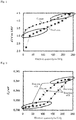
- Fig. 1 is a graph illustrating a result in which a relationship between an electric quantity and a charge-discharge voltage value is obtained using a lithium cell of a counter electrode Li with respect to a Li-excess active material.
- a horizontal axis indicates the electric quantity (mAh/g), and a vertical axis indicates the charge-discharge voltage value E (potential difference based on equilibrium potential VvsLi/Li + : Li/Li + ). At this point, the electric quantity corresponds to the SOC.
- an increase (charge) in SOC and a decrease (discharge) in SOC differ from each other in the voltage value. That is, the voltage values for the same SOC are different from each other, and have the hysteresis.
- a high SOC region is smaller than a low SOC region in the potential difference with respect to the same SOC, and the hysteresis is small.
- a small-hysteresis region where the SOC can be estimated from the voltage value using a voltage reference SOC-OCV curve (to be described later) is determined, and the SOC is estimated in the region.
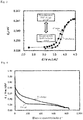
- Fig. 2 is a graph illustrating a transition of K absorption edge energy of Ni in the Li-excess active material calculated by X-ray absorption spectroscopy (XAFS measurement) with respect to the electric quantity.
- the horizontal axis indicates the electric quantity (mAh/g), and the vertical axis indicates K absorption edge energy E 0 (eV) of Ni.
- Fig. 3 is a graph illustrating the transition of the K absorption edge energy of Ni during charge-discharge.
- the horizontal axis indicates the charge-discharge voltage value E (VvsLi/Li + ), and the vertical axis indicates the K absorption edge energy E 0 (eV) of Ni.
- the transition of the K absorption edge energy of Ni in a charge reaction is not matched with the transition of the energy in a discharge reaction.
- the transition of the energy in the discharge reaction is not matched with the transition of the energy in the charge reaction. That is, it can be seen that a redox reaction except for Ni that has the hysteresis is mainly generated (it is assumed that this reaction is A).
- the reaction of A is an oxidation reaction in the high SOC region, and is a reductive reaction in the low SOC region.
- the K absorption edge energy of Ni in the charge reaction and discharge reaction changes substantially linearly with respect to the SOC.
- the charge and the discharge are substantially matched with each other in the K absorption edge energy of Ni.
- K absorption edge energy of Ni is the same, it is considered that a valence of Ni is equal, that a valence change of Ni corresponds substantially to a voltage value of at 1:1 in this voltage range, and that Ni reacts reversibly. That is, in the SOC region, the redox reaction having a small hysteresis indicated by the SOC-OCP characteristic is mainly generated (it is assumed that this reaction is B).
- the OCP means an open circuit potential.
- a reaction amount of B is larger than a reaction amount of A, and resultantly the hysteresis is smaller than that in the low SOC region.
- the lower voltage value (lower limit voltage value) in the region where the reaction of B is mainly generated is obtained by an experiment. At the lower limit voltage value, existence of the hysteresis is substantially switched. The oxidation amount and the reduction amount of the reaction of B are considered to be small.
- the SOC is estimated by the voltage reference based on a reached voltage value.
- the description is given by focusing only on an oxidation-reduction reaction of Ni.
- the reaction of B is not limited to the oxidation-reduction reaction of Ni.
- the reaction of B refers to a reaction with the small hysteresis of the storage amount-voltage value characteristic in one or a group of reactions generated by the active material according to the transition of the charge-discharge.
- the negative electrode of the energy storage device contains the active material having the large hysteresis
- the negative electrode includes SiO and graphite as active materials
- the hysteresis generated during the electrochemical reaction of SiO is larger than the hysteresis generated during the electrochemical reaction of graphite.
- Fig. 4 is a graph illustrating a result in which the relationship between the electric quantity and the charge-discharge voltage value is obtained using the lithium cell of the counter electrode Li with respect to the energy storage device.
- a horizontal axis indicates the electric quantity (mAh/g), and a vertical axis indicates a charge-discharge voltage value (VvsLi/Li + : Li/Li + potential difference based on the equilibrium potential).
- VvsLi/Li + Li/Li + potential difference based on the equilibrium potential
- the charge curve and the discharge curve differ from each other in the voltage value. That is, the voltage values for the same SOC are different from each other, and have the hysteresis.
- a high SOC region is smaller than a low SOC region in the potential difference with respect to the same SOC, and the hysteresis is small.
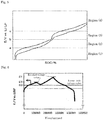
- Fig. 5 illustrates the charge-discharge curve when the region having the large hysteresis and the region having the small hysteresis appear alternately with increasing SOC (or voltage value).
- a horizontal axis indicates SOC (%), and a vertical axis indicates a voltage value (V).
- the positive electrode contains a plurality of Li-excess active materials having different positive electrodes
- the negative electrode contains a plurality of active materials having the large hysteresis
- each of the positive electrode and the negative electrode contains the active material having the large hysteresis
- the region having the large hysteresis and the region having the small hysteresis appear alternately, or appear while overlapping each other.
- the hysteresis is smaller than that in a region (1) where the voltage value is less than or equal to a.
- a reaction of C having the large hysteresis and a reaction of D having the small hysteresis are generated in the region (2). Because the reaction amount of D is large in the region (2), the hysteresis is smaller than that in the region (1) as a result.
- the hysteresis is smaller than that in the region (3) where the voltage value ranges from b to c.
- a reaction of E having the large hysteresis and a reaction of F having the small hysteresis are generated in the region (4). Because the reaction amount of E is large in the region (4), the hysteresis is smaller than that in the region (3) as a result.
- the lower limit voltage value a in the region (2) and the lower limit voltage value c in the region (4) are obtained by the experiment.
- the determination that the charge state or discharge state exists in the region (2) corresponding to the voltage region greater than or equal to the lower limit voltage value a is made based on the increase or decrease of the voltage value
- the determination that the charge state or discharge state exists in the region (4) corresponding to the voltage region greater than or equal to the lower limit voltage value c is made based on the increase or decrease of the voltage value
- the SOC is estimated by the voltage reference based on the reached voltage value (to be described later).
- the region of the voltage value is not limited to the case where the region of the voltage value is divided into two or four regions as described above.
- the SOC is relatively high and the SOC is estimated by the voltage reference in the region where the SOC is relatively high and the hysteresis is small.
- the lower limit voltage value When the OCV can be measured as the lower limit voltage value, the lower limit voltage value may be constant.
- a CCV Current Circuit Voltage
- update may be performed by lowering the lower limit voltage value according to a degree of degradation associated with the use of the energy storage device. An increase in internal resistance and an increase in deviation of capacity balance can be cited as an example of a cause of the degradation of the energy storage device.
- the deviation of the capacity balance means that a difference between an amount of side reaction except for a charge-discharge reaction in the positive electrode and an amount of side reactions except for the charge-discharge reaction in the negative electrode is generated to incompletely charge one of the positive electrode and the negative electrode, and the positive and negative electrodes have different capacities in which charged ions can reversibly enter and leave the electrode.
- the side reaction amount in the positive electrode is smaller than the side reaction amount in the negative electrode, when the "deviation of capacity balance" increases, the negative electrode cannot fully be charged and the electric quantity that can be reversibly taken out from the energy storage device decreases.
- the voltage value exceeds the lower limit voltage value by charging the battery, namely, the voltage value becomes a nobler potential than the lower limit voltage value, and the reached maximum voltage value is taken as a reached voltage value.
- a plurality of voltage reference SOC-OCV curves (hereinafter referred to as reference SOC-OCV curves) from a lower limit voltage value to a plurality of reached voltage values are stored in the memory table of the storage amount estimation device.
- reference SOC-OCV curves For example, an SOC-OCV curve a from the lower limit voltage value E0 V to the reached voltage value E1 V, an SOC-OCV curve b from the lower limit voltage value E0 V to the reached voltage value E2 V, and an SOC-OCV curve c from the lower limit voltage value E0 V to a reached voltage value E3 V are stored in the table 63b.
- E1 > E2 > E3 holds.
- the SOC-OCV curves a, b, c are not illustrated in the drawings.
- the SOC-OCV curves corresponding to all the reached voltage values are stored not discretely, but continuously. Instead of storing continuously the SOC-OCV curves, the SOC-OCV curve is discretely prepared, and a curve to be located between the adjacent SOC-OCV curves may be supplemented by interpolation calculation.
- the reference SOC-OCV curve is obtained as follows.
- a discharge OCV curve and a charge OCV curve are obtained when SOC (%) is changed from 40% to 100% for each point of SOC (%) from 40% to 100%.
- the discharge OCV curve can be obtained by passing a minute current in the discharge direction and measuring the voltage value at that time.
- the discharge is performed from the charge state to each SOC and stopped, and the stable voltage value can be measured.
- the charge OCV curve can be obtained when the above measurement is performed in a charge direction.
- the OCV curve obtained by averaging a discharge OCV curve and a charge OCV curve is used because the active material has the slight hysteresis even if the SOC is greater than or equal to 40%.
- the discharge OCV curve and the charge OCV curve, or corrected those may be used.
- the discharge OCP curve and the charge OCP curve may be corrected to the reference SOC-OCV curve for the energy storage device.
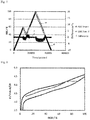
- Fig. 6 is a graph illustrating the transition of the voltage value with respect to time during the charge-discharge.
- the horizontal axis indicates time (second), and the vertical axis indicates a charge-discharge voltage value (VvsLi/Li + ).
- VvsLi/Li + charge-discharge voltage value
- the first charge was performed, the voltage value exceeded the lower limit voltage value E0 V and reached E3 V, and the first discharge was performed. After the voltage value reached E0 V, the second charge was performed, the voltage value reached E1 V, and the second discharge was performed.
- E3 V is stored as the first reached voltage value in the table.
- the reached voltage value is updated at a point of time the voltage value exceeds E3 V during the second charge.
- the SOC-OCV curve c is used until the voltage value reaches E3 V in the first discharge and the second charge.
- Another SOC-OCV curve stored in the table is used between E3 V and E1 V of the second charge.
- the SOC-OCV curve a is used from E1 V of the second discharge to E0 V of the lower limit voltage value.
- Fig. 7 is a graph illustrating a difference between the estimation of the SOC by the voltage reference of the embodiment and the estimation of the SOC by the conventional current integration when the charge-discharge in Fig. 6 is performed on the energy storage device of an initial product.
- the horizontal axis indicates time (second), the left vertical axis indicates SOC (%), and the right vertical axis indicates the difference (%).
- the discharge capacity is previously checked and a highly accurate ammeter is used, so that the discharge capacity of Q and the current value of I in equation (1) are accurate. It is considered that the discharge capacity of Q and the current value of I approximate the true values.
- d is the transition of the SOC obtained by the current integration
- e is the transition of the SOC obtained by the voltage reference using the SOC-OCV curves c and a
- f is the difference. The difference was obtained by (SOC calculated by voltage reference) - (SOC calculated by current integration).
- the difference is less than about ⁇ 4% and is small.
- the accuracy of the SOC estimation is lowered when the SOC-OCV curve is discretely prepared to supplement the curve to be located between the adjacent SOC-OCV curves by the interpolation calculation.
- the data amount becomes enormous in a use period of the energy storage device because the voltage reference SOC-OCV curve is prepared at predetermined time intervals according to the degradation of the energy storage device.
- ⁇ SOC is a difference between the SOC at a certain voltage value on the discharge SOC-OCV curve and the SOC at the same voltage value on the charge SOC-OCV curve.
- the reaction of A and the reaction of B are substantially independently generated.
- the reaction amount of A corresponds to ⁇ SOC, and does not affect the reaction of B.
- the reference SOC-OCV curve can easily be obtained by performing correction using ⁇ SOC based on the discharge SOC-OCV curve of the reaction of B.
- the reference SOC-OCV curve starting from each reached voltage value has a shape, in which the same discharge SOC-OCV curve is corrected while moved toward the charge SOC-OCV curve based on the same reaction of B and the reached voltage value at each starting point is cut as an upper end.
- Fig. 8 is an explanatory view illustrating this principle.
- the horizontal axis indicates SOC [%], and the vertical axis indicates the charge-discharge voltage value E (VvsLi/Li + ).
- (1) expresses the full discharge SOC-OCV curve
- (2) expresses the full charge SOC-OCV curve.
- the difference between the SOC at a certain reached voltage value on the discharge SOC-OCV curve (1) and the SOC at the same reached voltage value on the charge SOC-OCV curve (2) is ⁇ SOC.
- a SOC-OCV curve (3) is obtained by sliding the discharge SOC-OCV curve (1) onto the side of the charge SOC-OCV curve (2) in parallel with the horizontal axis by this ⁇ SOC.
- the SOC-OCV curve (3) in the range from the lower limit voltage value to the reached voltage value is taken as the reference SOC-OCV curve.
- the SOC corresponding to the acquired voltage value is read using the reference SOC-OCV curve.
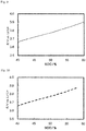
- Fig. 9 illustrates the SOC-OCV curve obtained by the measurement when the SOC ranges from 40% to 60%.
- the horizontal axis indicates SOC (%), and the vertical axis indicates the charge-discharge voltage value E (a potential difference based on the equilibrium potential VvsLi/Li + : Li/Li + ).
- Fig. 10 illustrates the reference SOC-OCV curve obtained by the above method when the SOC ranges from 40% to 60%.
- the horizontal axis indicates SOC (%), and the vertical axis indicates the charge-discharge voltage value E (a potential difference based on the equilibrium potential VvsLi/Li + : Li/Li + ).
- Fig. 11 is a graph illustrating a difference between the SOC-OCV curve a in Fig. 9 and the reference SOC-OCV curve b in Fig. 10 .
- the horizontal axis indicates the SOC (%)
- the left vertical axis indicates the charge-discharge voltage value E (the potential difference based on the equilibrium potential VvsLi/Li+ : Li/Li+)
- the right vertical axis indicates the difference (V).
- Difference voltage value of reference SOC-OCV curve ⁇ voltage value of measured SOC-OCV curve
- the SOC can be estimated with high accuracy using the reference SOC-OCV curve obtained by the above method.
- the reference SOCOCV curve corresponding the lower limit voltage value to each reached voltage value can easily be obtained by the above method. Only the full discharge SOCOCV curve and the full charge SOC-OCV curve are actually measured, and the work amount to be previously examined is significantly reduced.
- the reference SOC-OCV curve corresponding to each reached voltage value is directly generated from the measured full charge-discharge SOC-OCV curve, so that the accuracy of the SOC estimation is improved.
- the reference SOC-OCV curve is generated according to the degradation of the energy storage device. In this case, only the full charge-discharge SOC-OCV curve is actually measured, and the work amount is significantly reduced in the use period of the energy storage device.
- the SOC is preferably estimated from the current electrochemical behavior and use history.
- a first embodiment will be described below by taking an energy storage module mounted on a vehicle as an example.
- FIG. 12 illustrates an example of the energy storage module.
- An energy storage module 50 includes a plurality of energy storage devices 200, a monitoring device 100, and a housing case 300 that stores the plurality of energy storage devices 200 and the monitoring device 100.
- the energy storage module 50 may be used as a power source for an electric vehicle (EV) or a plug-in hybrid electric vehicle (PHEV).
- EV electric vehicle
- PHEV plug-in hybrid electric vehicle
- the energy storage device 200 is not limited to a prismatic cell, but may be a cylindrical cell or a pouch cell.
- the monitoring device 100 may be a circuit board disposed opposite to the plurality of energy storage devices 200.
- the monitoring device 100 monitors a state of the energy storage device 200.
- the monitoring device 100 may be a storage amount estimation device.
- a computer or a server that is connected to the monitoring device 100 in a wired or wireless manner may perform a storage amount estimation method based on information output from the monitoring device 100.
- Fig. 13 illustrates another example of the energy storage module.
- the energy storage module (hereinafter, referred to as a battery module) 1 may be a 12-volt power supply or a 48-volt power supply that is suitably mounted on an engine vehicle.
- Fig. 13 is a perspective view of a battery module 1 for a 12-V power supply
- Fig. 14 is an exploded perspective view of the battery module 1
- Fig. 15 is a block diagram of the battery module 1.
- the battery module 1 has a rectangular parallelepiped case 2.
- a plurality of lithium ion secondary batteries (hereinafter referred to as batteries) 3, a plurality of bus bars 4, a BMU (Battery Management Unit) 6, and a current sensor 7 are accommodated in the case 2.
- the battery 3 includes a rectangular parallelepiped case 31 and a pair of terminals 32, 32 that is provided on one side surface of the case 31 and having different polarities.
- the case 31 houses an electrode assembly 33 in which a positive electrode plate, a separator, and a negative electrode plate are laminated.
- At least one of a positive active material included in the positive electrode plate and a negative active material included in the negative electrode plate of the electrode assembly 33 generates at least two electrochemical reactions depending on a transition of charge-discharge.
- a hysteresis of a storage amount-voltage value characteristic exhibiting during the generation of one electrochemical reaction is smaller than a hysteresis during the generation of the other electrochemical reaction.
- the positive active material examples include Li-excess active materials such as the above LiMeO 2 -Li 2 MnO 3 solid solution, a Li 2 OLiMeO 2 solid solution, a Li 3 NbO 4 -LiMeO 2 solid solution, a Li 4 WO 5 -LiMeO 2 solid solution, a L 14 TeO 5 -LiMeO 2 solid solution, a Li 3 SbO 4 -LiFeO 2 solid solution, a Li 2 RuO 3 -LiMeO 2 solid solution, and a Li 2 RuO 3 -Li 2 MeO 3 solid solution.
- Li-excess active materials such as the above LiMeO 2 -Li 2 MnO 3 solid solution, a Li 2 OLiMeO 2 solid solution, a Li 3 NbO 4 -LiMeO 2 solid solution, a Li 4 WO 5 -LiMeO 2 solid solution, a L 14 TeO 5 -LiMeO
- negative active materials examples include hard carbon, metals such as Si, Sn, Cd, Zn, Al, Bi, Pb, Ge, and Ag or alloys thereof, or chalcogenides containing these.
- SiO can be cited as an example of the chalcogenide.
- the technique of the present invention is applicable as long as at least one of the positive active materials and negative active materials is contained.
- the case 2 is made of a synthetic resin.
- the case 2 includes a case body 21, a lid 22 that closes an opening of the case body 21, a BMU housing 23 provided on an outer surface of the lid 22, a cover 24 covering the BMU housing 23, an inner lid 25, and a partition plate 26.
- the inner lid 25 and the partition plate 26 may not be provided.
- the battery 3 is inserted between the partition plates 26 of the case body 21.
- a plurality of metal bus bars 4 are placed on the inner lid 25.
- the inner lid 25 is disposed on a terminal surface on which the terminal 32 of the battery 3 is provided, the adjacent terminals 32 of the adjacent batteries 3 are connected to each other by the bus bar 4, and the batteries 3 are connected in series.
- the BMU housing 23 has a box shape, and includes a protrusion 23a protruding outward in a prismatic shape in a central portion of one long side surface.
- a pair of external terminals 5, 5 that are made of metal such as a lead alloy and has different polarities is provided on both sides of the protrusion 23a in the lid 22.
- the BMU 6 is configured by mounting an information processor 60, a voltage measuring unit 8, and a current measuring unit 9 on a substrate.
- the BMU 6 is housed in the BMU housing 23 and the BMU housing 23 is covered with the cover 24, whereby the battery 3 and the BMU 6 are connected to each other.
- the information processor 60 includes a CPU 62 and a memory 63.
- the memory 63 stores an SOC estimation program 63a of the embodiment and a table 63b that stores a full charge SOC-OCV curve and a discharge SOC-OCV curve.
- the SOC-OCV curve is not limited to the case where the SOC-OCV curve is stored in the table 63b, but may be stored in the memory 63 as a numerical expression.
- the full charge SOC-OCV curve and the discharge SOC-OCV curve are obtained by measurement at predetermined time intervals. As the battery 3 is degraded, the charge-discharge SOC-OCV curve is updated. The charge-discharge SOC-OCV curve may be measured each time the battery 3 is used.
- the SOC estimation program 63a is provided while stored in a computer-readable recording medium 70 such as a CD-ROM, DVD-ROM, and USB memory, and is stored in the memory 63 by installing the SOC estimation program 63a in the BMU 6.
- the SOC estimation program 63a may be acquired from an external computer (not illustrated) connected to a communication network, and stored in the memory 63.
- the CPU 62 performs an SOC estimation processing (to be described later) according to the SOC estimation program 63a read from the memory 63.
- the voltage measuring unit 8 is connected to both ends of the battery 3 via a voltage detection line, and measures the voltage value of each battery 3 at predetermined time intervals.
- the current measuring unit 9 measures a current value passed through the battery 3 via the current sensor 7 at predetermined time intervals.
- the external terminals 5, 5 of the battery module 1 are connected to a starter motor that starts the engine and a load 11 such as an electric component.
- An ECU (Electronic Control Unit) 10 is connected to the BMU 6 and the load 11.
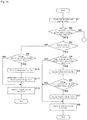
- Figs. 16 and 17 are flowcharts illustrating a procedure of the SOC estimation processing performed by the CPU 62.
- the CPU 62 repeats pieces of processing from S1 at predetermined intervals.
- the CPU 62 acquires the voltage value and the current value between the terminals of the battery 3 (S1). Because the lower limit voltage value and the reached voltage value (to be described later) are the OCV, it is necessary to correct the acquired voltage value to OCV when the current amount of the battery 3 is large.
- the correction value to OCV is obtained by estimating the voltage value at the current value of zero using a regression line from the data of the pluralities of voltage values and current values. When the amount of current flowing through the battery 3 is as small as a dark current (a minute current), the acquired voltage value can be regarded as OCV.
- the CPU 62 determines whether an absolute value of the current value is greater than or equal to a threshold (S2).
- the threshold is set in order to determine whether the battery 3 is in a charge state, a discharge state, or a resting state.
- the processing proceeds to S13.
- the CPU 62 determines whether the current value is greater than zero (S3). It is determined that the battery 3 is in the charge state when the current value is larger than zero. When the CPU 62 determines that the current value is less than zero (NO in S3), the processing proceeds to S9.
- the CPU 62 determines whether the voltage value is greater than or equal to the lower limit voltage value (S4). When the CPU 62 determines that the voltage value is less than the lower limit voltage value (NO in S4), the processing proceeds to S8.
- the CPU 62 When determining that the voltage value is greater than or equal to the lower limit voltage value (YES in S4), the CPU 62 turns on a voltage reference flag (S5).
- the CPU 62 determines whether the acquired voltage value is greater than the previous reached voltage value (S6). When the CPU 62 determines that the voltage value is not greater than the previous reached voltage value (NO in S6), the processing proceeds to S8.
- the CPU 62 When determining that the voltage value is greater than the previous reached voltage value (YES in S6), the CPU 62 updates the voltage value to the reached voltage value in the memory 63 (S7).
- the CPU 62 estimates the SOC by the current integration (S8), and ends the processing.
- the CPU 62 determines whether the voltage value is less than the lower limit voltage value in S9 (S9). When the CPU 62 determines that the voltage value is greater than or equal to the lower limit voltage value (NO in S9), the processing proceeds to S12.
- the CPU 62 When determining that the voltage value is less than the lower limit voltage value (YES in S9), the CPU 62 turns off the voltage reference flag (S10).
- the CPU 62 resets the reached voltage value (S11).
- the CPU 62 estimates the SOC by the current integration (S12), and ends the processing.
- the CPU 62 determines whether the voltage reference flag is turned on (S13). When the CPU 62 determines that the voltage reference flag is not turned on (NO in S13), the processing proceeds to S16.
- the CPU 62 determines whether a setting time elapses since the battery 3 is determined to be in the resting state in S2 (S14).
- the setting time a sufficient time for considering the acquired voltage value as the OCV is previously obtained by an experiment. It is determined whether the setting time exceeds the time based on the number of acquisition times and the acquisition interval of the current value after the battery 3 is determined to be in the resting state. Consequently, the SOC can be estimated with higher accuracy in the resting state.
- the CPU 62 estimates the SOC by the current integration in S18, and ends the processing.
- the acquired voltage value can be regarded as the OCV.
- the CPU 62 reads the charge-discharge SOC-OCV curve from the table 63b (S15).
- the CPU 62 generates the reference SOC-OCV curve (S16).
- the CPU 62 moves the discharge SOC-OCV curve in parallel to the horizontal axis such that a first point corresponding to the reached voltage value on the discharge SOC-OCV curve overlaps a second point corresponding to the reached voltage value on the charge SOC-OCV curve. That is, the discharge SOC-OCV curve is translated by ⁇ SOC.
- the curve is cut from the lower limit voltage value to the reached voltage value to generate the reference SOCOCV curve.
- the CPU 62 reads the SOC corresponding to the voltage value acquired in S1 in the reference SOC-OCV curve to estimate the SOC (S17), and ends the processing.
- the voltage value rises and falls, namely, a high inflection point among inflection points where the charge is switched to the discharge is set to the reached voltage value.
- the voltage value acquired from the voltage measuring unit 8 by the CPU 62 varies somewhat depending on the current value, so that the voltage value can be corrected by obtaining a correction coefficient through the experiment.
- the hysteresis is small (substantially no hysteresis), and the SOC is estimated based on the reference SOC-OCV curve and the current voltage value in the range from the lower limit voltage value to the reached voltage value, so that the estimation of SOC can be estimated with high accuracy.
- the OCV reset can be performed with high accuracy.
- the SOC can be estimated in both the charge and the discharge.
- the SOC can be estimated only from the history of the voltage value. Only when the acquired voltage value exceeds the previous reached voltage value, the update of the reached voltage value can accurately estimate the SOC as compared with Patent Document 1 that selects the SOC-OCV curve based on the final voltage value during the charge.
- the reference SOC-OCV curve is generated by translating the discharge SOC-OCV curve by ⁇ SOC based on the reached voltage value stored in the memory 63.
- the reference SOC-OCV curve corresponding to all the reached voltage values is generated from one discharge SOC-OCV curve. It is not necessary to store the reference SOC-OCV curve in the memory 63 by the measurement for each reached voltage value. That is, the reference SOC-OCV curve corresponding the lower limit voltage value to each reached voltage value can easily be obtained. Only the full charge-discharge SOC-OCV curve is actually measured, which significantly reduces the work amount.
- the storage amount is not limited to the SOC, but the current amount of energy, such as amount of power, which is stored in the battery 3, can be estimated.
- the case where the SOC is estimated in real time will be described in a second embodiment.
- the configuration is the same as that of the first embodiment except for the SOC estimation processing performed by the CPU 62.
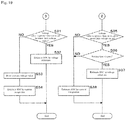
- Figs. 18 and 19 are flowcharts illustrating the procedure of the SOC estimation processing performed by the CPU 62.
- the CPU 62 repeats the pieces of processing from S21 at predetermined intervals.
- the CPU 62 acquires the voltage value and the current value between the terminals of the battery 3 (S21).
- the CPU 62 determines whether the absolute value of the current value is greater than or equal to a threshold (S22).
- the threshold is set in order to determine whether the battery 3 is in a charge state, a discharge state, or a resting state.
- the processing proceeds to S33.
- the CPU 62 determines whether the current value is greater than zero (S23). When the current value is larger than zero, the battery 3 is in the charge state. When the CPU 62 determines that the current value is not greater than zero (NO in S23), the processing proceeds to S29.
- the CPU 62 determines whether the voltage value is greater than the previous reached voltage value (S24). For example, the voltage value may be corrected by estimating the value when the current value of zero, using a regression straight line from the data of pluralities of voltage values and current values. When the CPU 62 determines that the voltage value is not greater than the previous reached voltage value (NO in S24), the processing proceeds to S26.
- the CPU 62 When determining that the voltage value is larger than the previous reached voltage value (YES in S24), the CPU 62 updates the voltage value to the reached voltage value (S25).
- the CPU 62 determines whether the voltage value is greater than or equal to the lower limit voltage value (S26). When determining that the voltage value is less than the lower limit voltage value (NO in S26), the CPU 62 estimates the SOC by the current integration (S30), and ends the processing.
- the CPU 62 When determining that the voltage value is greater than or equal to the lower limit voltage value (YES in S26), the CPU 62 reads the charge-discharge SOC-OCV curve from the table 63b (S27).
- the CPU 62 generates the reference SOC-OCV curve (S28).
- the CPU 62 moves the discharge SOC-OCV curve in parallel to the horizontal axis such that a first point corresponding to the reached voltage value on the discharge SOC-OCV curve overlaps a second point corresponding to the reached voltage value on the charge SOC-OCV curve. That is, the discharge SOC-OCV curve is translated by ⁇ SOC.
- the CPU 62 cuts the curve from the lower limit voltage value to the reached voltage value to generate the reference SOC-OCV curve.
- the CPU 62 reads the SOC from the current OCV in the reference SOC-OCV curve to estimate the SOC (S29), and ends the processing.
- the CPU 62 calculates the current OCV from the voltage value and the current value acquired in S21.
- the OCV can be calculated by estimating the voltage value at the current value of zero using the regression line from the data of the pluralities of voltage values and current values. When the current value is as small as the dark current value, the acquired voltage value can be read as the OCV.
- the CPU 62 determines whether the voltage value is greater than or equal to the lower limit voltage value in S29 (S31).
- the CPU 62 estimates the SOC by the voltage reference in the same manner as described above (S32).
- the CPU 62 When determining that the voltage value is less than the lower limit voltage value (NO in S31), the CPU 62 resets the reached voltage value (S33).
- the CPU 62 estimates the SOC by the current integration (S34), and ends the processing.
- the CPU 62 determines whether the voltage value is greater than or equal to the lower limit voltage value (S35). When the CPU 62 determines that the voltage value is less than the lower limit voltage value (NO in S36), the processing proceeds to S36.
- the CPU 62 determines whether the setting time elapses since the battery 3 is determined to be in the resting state in S22 (S36). As for the setting time, a sufficient time for considering the acquired voltage value as the OCV is previously obtained by an experiment.
- the CPU 62 estimates the SOC by the current integration (S38), and ends the processing.
- the CPU 62 determines that the setting time elapses (YES in S36), the acquired voltage value can be regarded as the OCV, the SOC is estimated by the voltage reference in the same manner as described above (S37), and the processing is ended.
- the SOC can be estimated in real time during the charge-discharge.
- the SOC is estimated based on the reference SOC-OCV curve and the current voltage value in the range from the lower limit voltage value to the reached voltage value, the hysteresis being substantially free in the range. Thus, the SOC is accurately estimated.
- the discharge SOC-OCV curve stored in the table 63b is translated by ⁇ SOC to generate the reference SOC-OCV curve.
- the reference SOC-OCV curve corresponding to all the reached voltage values is generated from one discharge SOC-OCV curve. It is not necessary to store the reference SOC-OCV curve in the memory 63 by the measurement for each reached voltage value. That is, the reference SOC-OCV curve corresponding the lower limit voltage value to each reached voltage value can easily be obtained. Only the full charge-discharge SOC-OCV curve is actually measured, which significantly reduces the work amount.
- the storage amount is not limited to the SOC, but the current amount of energy, such as amount of power, which is stored in the battery 3, can be estimated.
- the SOC can be estimated in both the charge and the discharge. Even if the charge-discharge are repeated with the complicated pattern, the SOC can be estimated based only on the history of the voltage values.
- the storage amount is not limited to the SOC, and the current amount of energy, such as amount of power, which is stored in the battery 3, can be estimated.
- a storage amount estimation device that estimates a storage amount of an energy storage device in which at least one of a positive electrode and a negative electrode contains an active material, at least two electrochemical reactions being generated in the active material depending on a transition of charge-discharge, a hysteresis between a storage amount-voltage value charge characteristic according to a transition of charge and a storage amount-voltage value discharge characteristic according to a transition of discharge during generation of one of the electrochemical reactions being smaller than a hysteresis during generation of the other electrochemical reaction in the active material
- the storage amount estimation device includes an estimator that estimates the storage amount using a voltage reference storage amount-voltage value characteristic obtained based on the storage amount-voltage value discharge characteristic when the one electrochemical reaction is generated more than the other electrochemical reaction.
- the storage amount is estimated based on the voltage reference storage amount-voltage value characteristic.
- the discharge electric quantity of one electrochemical reaction in the region can be regarded as the charge electric quantity of one electrochemical reaction. That is, the same voltage reference storage amount-voltage value characteristic can be used when the storage amount is estimated in the charge state and the discharge state.
- the storage amount-voltage value charge characteristic and the storage amount-voltage value discharge characteristic are acquired.
- the voltage reference storage amount-voltage value characteristic can easily be acquired using the storage amount-voltage value discharge characteristic in which one electrochemical reaction is generated.
- the storage amount of the high-capacity energy storage device containing the active material having the storage amount-voltage value characteristic exhibiting the hysteresis can easily and satisfactorily be estimated.
- the storage amount is not limited to the SOC, and the current amount of energy, such as amount of power, which is stored in the energy storage device, can be estimated.
- the dischargeable energy up to SOC 0% and the charge energy required up to SOC 100% can be predicted based on the charge-discharge curve.
- the storage amount estimation device when the one electrochemical reaction is generated more than the other electrochemical reaction, the storage amount is estimated based on a difference in storage amount between a storage amount-voltage value charge characteristic and a storage amount-voltage value discharge characteristic at an identical voltage value and the voltage reference storage amount-voltage value characteristic obtained by moving the storage amount-voltage value discharge characteristic toward the storage amount-voltage value charge characteristic.
- the storage amount-voltage value charge characteristic and the storage amount-voltage value discharge characteristic are acquired.
- the difference between the storage amounts of both the characteristics at the identical voltage value ( ⁇ storage amount) corresponds to another electrochemical reaction.
- One electrochemical reaction and the other electrochemical reaction are substantially independently generated.
- the reaction amount of the other electrochemical reaction corresponds to the ⁇ storage amount, and hardly affects one electrochemical reaction.
- the voltage reference storage amount-voltage value characteristic is obtained by moving the difference in storage amount between the storage amount-voltage value charge characteristic and the storage amount-voltage value discharge characteristic at the same voltage value and the storage amount-voltage value discharge characteristic toward the storage amount-voltage value charge characteristic. That is, the voltage reference storage amount-voltage value characteristic starting from each voltage value has the shape, in which the same storage amount-voltage value discharge characteristic is moved toward the storage amount-voltage value charge characteristic based on the same one electrochemical reaction and the voltage value at each starting point is cut as the upper end.
- the storage amount is accurately estimated.
- the storage amount estimation device further includes: a voltage acquisition unit that acquires a voltage value of the energy storage device; and a setting unit that sets a reached voltage value based on a voltage value after the voltage value acquired by the voltage acquisition unit is higher than a lower limit voltage value at which existence of the hysteresis is substantially switched.
- the identical voltage value is the reached voltage value.
- the reached voltage value is set to generate the voltage reference storage amount-voltage value characteristic. Even in the case where the charge-discharge is repeated with the complicated pattern, the voltage reference storage amount-voltage value characteristic can be generated only by the history of the voltage value to estimate the storage amount.
- the estimator refers to the moving storage amount-voltage value characteristic to estimate the storage amount when the voltage value acquired by the voltage acquisition unit exists between the lower limit voltage value and the reached voltage value.
- the reaction amount of the other electrochemical reaction is small in the range from the lower limit voltage value to the reached voltage value, one electrochemical reaction being mainly generated and the hysteresis being small in the range.
- One electrochemical reaction is mainly generated in the charge-discharge reaction.
- the storage amount is estimated based on the voltage reference storage amount-voltage value characteristic and the acquired voltage value. Thus, the storage amount is accurately estimated.
- the setting unit stores the reached voltage value in a storage unit, and updates the acquired voltage value to the reached voltage value when the voltage value acquired by the voltage acquisition unit is larger than the reached voltage value previously stored in the storage unit.
- the storage amount can accurately be estimated by generating the voltage reference storage amount-voltage value characteristic based on the updated reached voltage value.
- the storage amount estimation device preferably the storage amount is an SOC.
- the estimation of the SOC for a high-capacity material improves applicability to the existing control system. Based on the SOC, the storage amount such as the dischargeable energy can easily be calculated.
- the storage amount estimation device can accurately estimate the charge state of the energy storage device in which the electrode material having the hysteresis is used with no use of a special sensor or additional component, the OCV and the SOC not corresponding to each other on a one-to-one manner in the electrode material.
- the energy storage module includes a plurality of energy storage devices and any one of the above storage amount estimation devices.
- the plurality of energy storage devices are connected in series. Sometimes the plurality of energy storage devices are connected in series and in parallel.
- the storage amount of each energy storage device is accurately estimated by the storage amount estimation device, so that the performance of the energy storage module can be exerted at the maximum.
- the energy storage module is suitably used as a power source for an EV or a PHEV that has a particularly high demand for the high capacity.
- a storage amount estimation method for estimating a storage amount of an energy storage device in which at least one of a positive electrode and a negative electrode contains an active material, at least two electrochemical reactions being generated in the active material depending on a transition of charge-discharge, a hysteresis between a storage amount-voltage value charge characteristic according to a transition of charge and a storage amount-voltage value discharge characteristic according to a transition of discharge during generation of one of the electrochemical reactions being smaller than a hysteresis during generation of the other electrochemical reaction in the active material
- the storage amount estimation method includes: acquiring a voltage reference storage amount-voltage value characteristic obtained based on the storage amount-voltage value discharge characteristic when the one electrochemical reaction is generated more than the other electrochemical reaction; and estimating the storage amount based on the voltage reference storage amount-voltage value characteristic.
- the storage amount is estimated based on the voltage reference storage amount-voltage value characteristic.
- the discharge electric quantity of one electrochemical reaction in the region can be regarded as the charge electric quantity of one electrochemical reaction. That is, the same voltage reference storage amount-voltage value characteristic can be used when the storage amount is estimated in the charge state and the discharge state.
- the storage amount-voltage value charge characteristic and the storage amount-voltage value discharge characteristic are acquired.
- the voltage reference storage amount-voltage value characteristic can easily be acquired using the storage amount-voltage value discharge characteristic in which one electrochemical reaction is generated.
- the voltage reference storage amount-voltage value characteristic As compared with the case where the voltage reference storage amount-voltage value characteristic to be located between the adjacent voltage reference storage amount-voltage value characteristics is supplemented by the interpolation calculation, the voltage reference storage amount-voltage value characteristic is generated corresponding to each reached voltage value, so that the accuracy of the storage amount estimation is improved.
- the storage amount of the high-capacity energy storage device containing the active material having the storage amount-voltage value characteristic exhibiting the hysteresis can easily and satisfactorily be estimated.
- the storage amount can be estimated in both the charge and the discharge.
- the inflection point relating to the increase or decrease of the voltage value is set to the reached voltage value to select the storage amount-voltage value characteristic. Even if the charge-discharge are repeated with the complicated pattern, the storage amount can be estimated based only on the history of the voltage values.
- the storage amount is not limited to the SOC, and the current amount of energy, such as amount of power, which is stored in the energy storage device, can be estimated.
- the storage amount estimation method further includes: setting a reached voltage value based on a voltage value after the acquired voltage value is higher than a lower limit voltage value at which existence of the hysteresis is substantially switched; acquiring a difference in storage amount between the storage amount-voltage value charge characteristic and the storage amount-voltage value discharge characteristic at the reached voltage value and the voltage reference storage amount-voltage value characteristic obtained by moving the storage amount-voltage value discharge characteristic toward the storage amount-voltage value charge characteristic; and referring to the voltage reference storage amount-voltage value characteristic to estimate the storage amount when the acquired voltage value exists between the lower limit voltage value and the reached voltage value.
- the storage amount-voltage value charge characteristic and the storage amount-voltage value discharge characteristic are acquired.
- the difference between the storage amounts of both the characteristics at the identical voltage value ( ⁇ storage amount) corresponds to another electrochemical reaction.
- the reaction amount of the other electrochemical reaction corresponds to the ⁇ storage amount, and hardly affects one electrochemical reaction.
- the voltage reference storage amount-voltage value characteristic can easily be acquired by performing the correction using the ⁇ storage amount based on the storage amount-voltage value discharge characteristic in which one electrochemical reaction is generated. That is, the voltage reference storage amount-voltage value characteristic starting from each voltage value has the shape, in which the same storage amount-voltage value discharge characteristic is moved toward the storage amount-voltage value charge characteristic based on the same one electrochemical reaction and the voltage value at each starting point is cut as the upper end.
- the reached voltage value is set to generate the voltage reference storage amount-voltage value characteristic. Even in the case where the charge-discharge is repeated with the complicated pattern, the voltage reference storage amount-voltage value characteristic can be generated only by the history of the voltage value to estimate the storage amount.
- the storage amount is estimated based on the voltage reference storage amount-voltage value characteristic and the current voltage value. Thus, the storage amount is accurately estimated.
- a computer program that causes a computer to perform pieces of processing, the computer estimating a storage amount of an energy storage device in which at least one of a positive electrode and a negative electrode contains an active material, at least two electrochemical reactions being generated in the active material depending on a transition of charge-discharge, a hysteresis between a storage amount-voltage value charge characteristic according to a transition of charge and a storage amount-voltage value discharge characteristic according to a transition of discharge during generation of one of the electrochemical reactions being smaller than a hysteresis during generation of the other electrochemical reaction in the active material
- the pieces of processing includes: acquiring the storage amount-voltage value discharge characteristics and the storage amount-voltage value charge characteristics; determining whether the acquired voltage value is higher than a lower limit voltage value at which existence of the hysteresis is substantially switched; setting the reached voltage value when the voltage value is determined to be higher than the lower limit voltage value;
- the storage amount estimation device of the present invention is not limited to the case where the storage amount estimation device is applied to a vehicle-mounted lithium ion secondary battery, but can also be applied to other energy storage modules such as a railway regeneration power storage device and a solar power generating system.
- the energy storage module through which the minute current is passed the voltage value between the positive electrode terminal and the negative electrode terminal of the energy storage device or the voltage value between the positive electrode terminal and the negative electrode terminal of the energy storage module can be regarded as the OCV.
- the energy storage device is not limited to the lithium ion secondary battery, but may be another secondary battery or an electrochemical cell having the hysteresis characteristic.
- a CMU Cell Monitoring Unit
- the storage amount estimation device may be a part of the energy storage module in which the monitoring device 100 or the like is incorporated.
- the storage amount estimation device may be configured separately from the energy storage device or the energy storage module, and connected to the energy storage module including the energy storage device that is the estimation target of the heat storage amount during the estimation of the heat storage amount.
- the heat storage amount estimation device may remotely monitor the energy storage device and the energy storage module.
Landscapes
- Physics & Mathematics (AREA)
- General Physics & Mathematics (AREA)
- Engineering & Computer Science (AREA)
- Manufacturing & Machinery (AREA)
- Chemical & Material Sciences (AREA)
- Chemical Kinetics & Catalysis (AREA)
- Electrochemistry (AREA)
- General Chemical & Material Sciences (AREA)
- Power Engineering (AREA)
- Secondary Cells (AREA)
- Charge And Discharge Circuits For Batteries Or The Like (AREA)
- Tests Of Electric Status Of Batteries (AREA)
Applications Claiming Priority (2)
| Application Number | Priority Date | Filing Date | Title |
|---|---|---|---|
| JP2017065005 | 2017-03-29 | ||
| PCT/JP2018/013053 WO2018181620A1 (fr) | 2017-03-29 | 2018-03-28 | Dispositif d'estimation de quantité d'électricité stockée, module de stockage d'électricité, procédé d'estimation de quantité d'électricité stockée et programme d'ordinateur |
Publications (3)
| Publication Number | Publication Date |
|---|---|
| EP3605122A1 true EP3605122A1 (fr) | 2020-02-05 |
| EP3605122A4 EP3605122A4 (fr) | 2020-04-01 |
| EP3605122B1 EP3605122B1 (fr) | 2024-11-27 |
Family
ID=63855243
Family Applications (1)
| Application Number | Title | Priority Date | Filing Date |
|---|---|---|---|
| EP18774740.7A Active EP3605122B1 (fr) | 2017-03-29 | 2018-03-28 | Dispositif d'estimation de quantité d'électricité stockée, module de stockage d'électricité, procédé d'estimation de quantité d'électricité stockée et programme d'ordinateur |
Country Status (4)
| Country | Link |
|---|---|
| US (1) | US11181584B2 (fr) |
| EP (1) | EP3605122B1 (fr) |
| JP (1) | JP6406468B1 (fr) |
| CN (1) | CN110462413B (fr) |
Cited By (3)
| Publication number | Priority date | Publication date | Assignee | Title |
|---|---|---|---|---|
| EP3657190A4 (fr) * | 2017-07-19 | 2020-06-03 | GS Yuasa International Ltd. | Dispositif d'estimation, dispositif de stockage d'énergie, procédé d'estimation et programme informatique |
| EP3657189A4 (fr) * | 2017-07-19 | 2020-06-03 | GS Yuasa International Ltd. | Dispositif d'estimation, dispositif de stockage d'énergie, procédé d'estimation et programme informatique |
| US11237214B2 (en) | 2017-07-19 | 2022-02-01 | Gs Yuasa International Ltd. | Estimation device, energy storage apparatus, estimation method, and computer program |
Families Citing this family (6)
| Publication number | Priority date | Publication date | Assignee | Title |
|---|---|---|---|---|
| KR102458526B1 (ko) * | 2018-02-07 | 2022-10-25 | 주식회사 엘지에너지솔루션 | 배터리의 동작 상태에 따라 soc를 추정하는 장치 및 방법 |
| JP7040284B2 (ja) * | 2018-05-23 | 2022-03-23 | トヨタ自動車株式会社 | 二次電池の劣化状態推定方法、劣化状態推定装置、制御方法、及び制御システム |
| CN111856178B (zh) * | 2020-03-31 | 2021-10-08 | 同济大学 | 一种基于锂离子电容器电化学特征的soc分区估计方法 |
| KR102493221B1 (ko) * | 2020-12-04 | 2023-01-30 | 주식회사 에이치에너지 | 적응적 SoC 추정을 통한 ESS 최적 운전 시스템 및 방법 |
| CN115249991B (zh) * | 2021-04-28 | 2024-11-12 | 宁德新能源科技有限公司 | 充电方法以及电子设备 |
| JP2025012713A (ja) | 2023-07-14 | 2025-01-24 | トヨタ自動車株式会社 | 蓄電池の管理方法および電池管理システム |
Family Cites Families (19)
| Publication number | Priority date | Publication date | Assignee | Title |
|---|---|---|---|---|
| JP4292721B2 (ja) * | 2001-02-14 | 2009-07-08 | 株式会社日本自動車部品総合研究所 | ハイブリッド車の電池状態制御方法 |
| US7570024B2 (en) * | 2004-04-06 | 2009-08-04 | Cobasys, Llc | Battery state of charge voltage hysteresis estimator |
| US7795874B1 (en) * | 2007-10-10 | 2010-09-14 | Commissariat A L'energie Atomique | Method of estimation of the state of charge of a lead-acid battery |
| US7957921B2 (en) * | 2008-02-19 | 2011-06-07 | GM Global Technology Operations LLC | Model-based estimation of battery hysteresis |
| JP5866987B2 (ja) | 2011-11-10 | 2016-02-24 | 日産自動車株式会社 | 二次電池の制御装置およびsoc検出方法 |
| JP2013158087A (ja) * | 2012-01-27 | 2013-08-15 | Toyota Motor Corp | 蓄電システム及び充電状態推定方法 |
| JP6065561B2 (ja) * | 2012-03-08 | 2017-01-25 | 日産自動車株式会社 | 二次電池の制御装置およびsoc検出方法 |
| JP2014059206A (ja) * | 2012-09-18 | 2014-04-03 | Toyota Industries Corp | 充電状態推定装置及び充電状態推定方法 |
| JP6221237B2 (ja) | 2013-01-21 | 2017-11-01 | 株式会社豊田自動織機 | 充電率推定装置および充電率推定方法 |
| JP5994680B2 (ja) * | 2013-02-27 | 2016-09-21 | 株式会社豊田自動織機 | 電池残容量推定方法及び装置 |
| US9500713B1 (en) * | 2013-03-05 | 2016-11-22 | Qnovo Inc. | Circuitry and techniques for determining an SOC of a battery/cell having a silicon-based anode and a fuel gauge therefor |
| US20160254542A1 (en) | 2013-10-23 | 2016-09-01 | Hitachi, Ltd. | Cathode Active Material for Lithium Ion Secondary Batteries, and Lithium Ion Secondary Battery |
| JP6037369B2 (ja) * | 2014-02-25 | 2016-12-07 | 三菱電機株式会社 | 二次電池のsoc推定装置 |
| US20150276885A1 (en) * | 2014-03-25 | 2015-10-01 | Stmicroelectronics International N.V. | Method of Computing State of Charge and Battery State of Charge Monitor |
| US9977087B2 (en) * | 2014-04-23 | 2018-05-22 | Mitsubishi Electric Corporation | Device and method for estimating remaining battery capacity |
| JP2015230193A (ja) * | 2014-06-04 | 2015-12-21 | ソニー株式会社 | 劣化状態推定装置、充電状態推定装置、ocvカーブ算出生成装置および蓄電装置 |
| CN104297689B (zh) * | 2014-09-04 | 2017-05-24 | 中兴通讯股份有限公司 | 一种显示电池的电量的方法、装置及电子设备 |
| JP6525648B2 (ja) | 2015-03-10 | 2019-06-05 | 株式会社Nttファシリティーズ | 電池容量推定システム、電池容量推定方法および電池容量推定プログラム |
| CN106569143B (zh) * | 2016-11-11 | 2019-11-08 | 常州普莱德新能源电池科技有限公司 | 一种在线计算电芯容量与soh的方法、系统及电动车辆 |
-
2018
- 2018-03-28 JP JP2018062290A patent/JP6406468B1/ja active Active
- 2018-03-28 EP EP18774740.7A patent/EP3605122B1/fr active Active
- 2018-03-28 US US16/498,280 patent/US11181584B2/en active Active
- 2018-03-28 CN CN201880022409.XA patent/CN110462413B/zh active Active
Cited By (3)
| Publication number | Priority date | Publication date | Assignee | Title |
|---|---|---|---|---|
| EP3657190A4 (fr) * | 2017-07-19 | 2020-06-03 | GS Yuasa International Ltd. | Dispositif d'estimation, dispositif de stockage d'énergie, procédé d'estimation et programme informatique |
| EP3657189A4 (fr) * | 2017-07-19 | 2020-06-03 | GS Yuasa International Ltd. | Dispositif d'estimation, dispositif de stockage d'énergie, procédé d'estimation et programme informatique |
| US11237214B2 (en) | 2017-07-19 | 2022-02-01 | Gs Yuasa International Ltd. | Estimation device, energy storage apparatus, estimation method, and computer program |
Also Published As
| Publication number | Publication date |
|---|---|
| JP2018169398A (ja) | 2018-11-01 |
| EP3605122B1 (fr) | 2024-11-27 |
| CN110462413B (zh) | 2021-12-07 |
| US20200041574A1 (en) | 2020-02-06 |
| EP3605122A4 (fr) | 2020-04-01 |
| CN110462413A (zh) | 2019-11-15 |
| US11181584B2 (en) | 2021-11-23 |
| JP6406468B1 (ja) | 2018-10-17 |
Similar Documents
| Publication | Publication Date | Title |
|---|---|---|
| EP3605122B1 (fr) | Dispositif d'estimation de quantité d'électricité stockée, module de stockage d'électricité, procédé d'estimation de quantité d'électricité stockée et programme d'ordinateur | |
| EP3605125B1 (fr) | Dispositif d'estimation de quantité d'électricité stockée, module de stockage d'électricité, procédé d'estimation de quantité d'électricité stockée et programme informatique | |
| JP7111015B2 (ja) | 推定装置、蓄電装置、推定方法、及びコンピュータプログラム | |
| EP3051305B1 (fr) | Méthode de détermination d'état pour batterie rechargeable, appareil de détermination d'état pour batterie rechargeable, système de batterie rechargeable, et appareil de commande de charge/décharge doté de l'appareil de détermination d'état | |
| US11079440B2 (en) | Management device, energy storage module, management method, and computer program | |
| JP7115345B2 (ja) | 推定装置、蓄電装置、推定方法、及びコンピュータプログラム | |
| WO2018181620A1 (fr) | Dispositif d'estimation de quantité d'électricité stockée, module de stockage d'électricité, procédé d'estimation de quantité d'électricité stockée et programme d'ordinateur | |
| US11237214B2 (en) | Estimation device, energy storage apparatus, estimation method, and computer program | |
| JP7666516B2 (ja) | 異常検知方法、異常検知装置、蓄電装置及びコンピュータプログラム | |
| JP7556287B2 (ja) | 劣化推定装置、劣化推定方法及びコンピュータプログラム | |
| US10761143B2 (en) | Storage amount estimation device, energy storage module, storage amount estimation method, and computer program | |
| WO2018181624A1 (fr) | Dispositif d'estimation de quantité d'électricité stockée, module de stockage d'électricité, procédé d'estimation de quantité d'électricité stockée et programme informatique | |
| WO2019017183A1 (fr) | Dispositif d'estimation, dispositif de stockage d'énergie, procédé d'estimation et programme informatique | |
| US11150303B2 (en) | Management device, energy storage module, management method, and computer program | |
| JP2021071415A (ja) | 蓄電量推定装置、蓄電量推定方法及びコンピュータプログラム |
Legal Events
| Date | Code | Title | Description |
|---|---|---|---|
| STAA | Information on the status of an ep patent application or granted ep patent |
Free format text: STATUS: THE INTERNATIONAL PUBLICATION HAS BEEN MADE |
|
| PUAI | Public reference made under article 153(3) epc to a published international application that has entered the european phase |
Free format text: ORIGINAL CODE: 0009012 |
|
| STAA | Information on the status of an ep patent application or granted ep patent |
Free format text: STATUS: REQUEST FOR EXAMINATION WAS MADE |
|
| 17P | Request for examination filed |
Effective date: 20190926 |
|
| AK | Designated contracting states |
Kind code of ref document: A1 Designated state(s): AL AT BE BG CH CY CZ DE DK EE ES FI FR GB GR HR HU IE IS IT LI LT LU LV MC MK MT NL NO PL PT RO RS SE SI SK SM TR |
|
| AX | Request for extension of the european patent |
Extension state: BA ME |
|
| A4 | Supplementary search report drawn up and despatched |
Effective date: 20200304 |
|
| RIC1 | Information provided on ipc code assigned before grant |
Ipc: G01R 31/382 20190101ALI20200227BHEP Ipc: H01M 10/48 20060101ALI20200227BHEP Ipc: G01R 31/36 20200101AFI20200227BHEP Ipc: H02J 7/00 20060101ALI20200227BHEP Ipc: G01R 31/3842 20190101ALI20200227BHEP |
|
| DAV | Request for validation of the european patent (deleted) | ||
| DAX | Request for extension of the european patent (deleted) | ||
| STAA | Information on the status of an ep patent application or granted ep patent |
Free format text: STATUS: EXAMINATION IS IN PROGRESS |
|
| 17Q | First examination report despatched |
Effective date: 20221028 |
|
| GRAP | Despatch of communication of intention to grant a patent |
Free format text: ORIGINAL CODE: EPIDOSNIGR1 |
|
| STAA | Information on the status of an ep patent application or granted ep patent |
Free format text: STATUS: GRANT OF PATENT IS INTENDED |
|
| INTG | Intention to grant announced |
Effective date: 20240715 |
|
| P01 | Opt-out of the competence of the unified patent court (upc) registered |
Free format text: CASE NUMBER: APP_51255/2024 Effective date: 20240910 |
|
| GRAS | Grant fee paid |
Free format text: ORIGINAL CODE: EPIDOSNIGR3 |
|
| GRAA | (expected) grant |
Free format text: ORIGINAL CODE: 0009210 |
|
| STAA | Information on the status of an ep patent application or granted ep patent |
Free format text: STATUS: THE PATENT HAS BEEN GRANTED |
|
| AK | Designated contracting states |
Kind code of ref document: B1 Designated state(s): AL AT BE BG CH CY CZ DE DK EE ES FI FR GB GR HR HU IE IS IT LI LT LU LV MC MK MT NL NO PL PT RO RS SE SI SK SM TR |
|
| REG | Reference to a national code |
Ref country code: GB Ref legal event code: FG4D |
|
| REG | Reference to a national code |
Ref country code: CH Ref legal event code: EP |
|
| REG | Reference to a national code |
Ref country code: IE Ref legal event code: FG4D |
|
| REG | Reference to a national code |
Ref country code: DE Ref legal event code: R096 Ref document number: 602018077005 Country of ref document: DE |
|
| REG | Reference to a national code |
Ref country code: LT Ref legal event code: MG9D |
|
| REG | Reference to a national code |
Ref country code: NL Ref legal event code: MP Effective date: 20241127 |
|
| PG25 | Lapsed in a contracting state [announced via postgrant information from national office to epo] |
Ref country code: HR Free format text: LAPSE BECAUSE OF FAILURE TO SUBMIT A TRANSLATION OF THE DESCRIPTION OR TO PAY THE FEE WITHIN THE PRESCRIBED TIME-LIMIT Effective date: 20241127 Ref country code: PT Free format text: LAPSE BECAUSE OF FAILURE TO SUBMIT A TRANSLATION OF THE DESCRIPTION OR TO PAY THE FEE WITHIN THE PRESCRIBED TIME-LIMIT Effective date: 20250327 Ref country code: IS Free format text: LAPSE BECAUSE OF FAILURE TO SUBMIT A TRANSLATION OF THE DESCRIPTION OR TO PAY THE FEE WITHIN THE PRESCRIBED TIME-LIMIT Effective date: 20250327 |
|
| PG25 | Lapsed in a contracting state [announced via postgrant information from national office to epo] |
Ref country code: NL Free format text: LAPSE BECAUSE OF FAILURE TO SUBMIT A TRANSLATION OF THE DESCRIPTION OR TO PAY THE FEE WITHIN THE PRESCRIBED TIME-LIMIT Effective date: 20241127 Ref country code: FI Free format text: LAPSE BECAUSE OF FAILURE TO SUBMIT A TRANSLATION OF THE DESCRIPTION OR TO PAY THE FEE WITHIN THE PRESCRIBED TIME-LIMIT Effective date: 20241127 |
|
| REG | Reference to a national code |
Ref country code: AT Ref legal event code: MK05 Ref document number: 1746161 Country of ref document: AT Kind code of ref document: T Effective date: 20241127 |
|
| PG25 | Lapsed in a contracting state [announced via postgrant information from national office to epo] |
Ref country code: BG Free format text: LAPSE BECAUSE OF FAILURE TO SUBMIT A TRANSLATION OF THE DESCRIPTION OR TO PAY THE FEE WITHIN THE PRESCRIBED TIME-LIMIT Effective date: 20241127 |
|
| PG25 | Lapsed in a contracting state [announced via postgrant information from national office to epo] |
Ref country code: ES Free format text: LAPSE BECAUSE OF FAILURE TO SUBMIT A TRANSLATION OF THE DESCRIPTION OR TO PAY THE FEE WITHIN THE PRESCRIBED TIME-LIMIT Effective date: 20241127 |
|
| PG25 | Lapsed in a contracting state [announced via postgrant information from national office to epo] |
Ref country code: NO Free format text: LAPSE BECAUSE OF FAILURE TO SUBMIT A TRANSLATION OF THE DESCRIPTION OR TO PAY THE FEE WITHIN THE PRESCRIBED TIME-LIMIT Effective date: 20250227 |
|
| PG25 | Lapsed in a contracting state [announced via postgrant information from national office to epo] |
Ref country code: LV Free format text: LAPSE BECAUSE OF FAILURE TO SUBMIT A TRANSLATION OF THE DESCRIPTION OR TO PAY THE FEE WITHIN THE PRESCRIBED TIME-LIMIT Effective date: 20241127 Ref country code: AT Free format text: LAPSE BECAUSE OF FAILURE TO SUBMIT A TRANSLATION OF THE DESCRIPTION OR TO PAY THE FEE WITHIN THE PRESCRIBED TIME-LIMIT Effective date: 20241127 Ref country code: GR Free format text: LAPSE BECAUSE OF FAILURE TO SUBMIT A TRANSLATION OF THE DESCRIPTION OR TO PAY THE FEE WITHIN THE PRESCRIBED TIME-LIMIT Effective date: 20250228 |
|
| PG25 | Lapsed in a contracting state [announced via postgrant information from national office to epo] |
Ref country code: PL Free format text: LAPSE BECAUSE OF FAILURE TO SUBMIT A TRANSLATION OF THE DESCRIPTION OR TO PAY THE FEE WITHIN THE PRESCRIBED TIME-LIMIT Effective date: 20241127 |
|
| PG25 | Lapsed in a contracting state [announced via postgrant information from national office to epo] |
Ref country code: RS Free format text: LAPSE BECAUSE OF FAILURE TO SUBMIT A TRANSLATION OF THE DESCRIPTION OR TO PAY THE FEE WITHIN THE PRESCRIBED TIME-LIMIT Effective date: 20250227 |
|
| PG25 | Lapsed in a contracting state [announced via postgrant information from national office to epo] |
Ref country code: SM Free format text: LAPSE BECAUSE OF FAILURE TO SUBMIT A TRANSLATION OF THE DESCRIPTION OR TO PAY THE FEE WITHIN THE PRESCRIBED TIME-LIMIT Effective date: 20241127 |
|
| PG25 | Lapsed in a contracting state [announced via postgrant information from national office to epo] |
Ref country code: DK Free format text: LAPSE BECAUSE OF FAILURE TO SUBMIT A TRANSLATION OF THE DESCRIPTION OR TO PAY THE FEE WITHIN THE PRESCRIBED TIME-LIMIT Effective date: 20241127 |
|
| PG25 | Lapsed in a contracting state [announced via postgrant information from national office to epo] |
Ref country code: EE Free format text: LAPSE BECAUSE OF FAILURE TO SUBMIT A TRANSLATION OF THE DESCRIPTION OR TO PAY THE FEE WITHIN THE PRESCRIBED TIME-LIMIT Effective date: 20241127 |
|
| PG25 | Lapsed in a contracting state [announced via postgrant information from national office to epo] |
Ref country code: RO Free format text: LAPSE BECAUSE OF FAILURE TO SUBMIT A TRANSLATION OF THE DESCRIPTION OR TO PAY THE FEE WITHIN THE PRESCRIBED TIME-LIMIT Effective date: 20241127 |
|
| PG25 | Lapsed in a contracting state [announced via postgrant information from national office to epo] |
Ref country code: SK Free format text: LAPSE BECAUSE OF FAILURE TO SUBMIT A TRANSLATION OF THE DESCRIPTION OR TO PAY THE FEE WITHIN THE PRESCRIBED TIME-LIMIT Effective date: 20241127 |
|
| PG25 | Lapsed in a contracting state [announced via postgrant information from national office to epo] |
Ref country code: CZ Free format text: LAPSE BECAUSE OF FAILURE TO SUBMIT A TRANSLATION OF THE DESCRIPTION OR TO PAY THE FEE WITHIN THE PRESCRIBED TIME-LIMIT Effective date: 20241127 |
|
| PG25 | Lapsed in a contracting state [announced via postgrant information from national office to epo] |
Ref country code: IT Free format text: LAPSE BECAUSE OF FAILURE TO SUBMIT A TRANSLATION OF THE DESCRIPTION OR TO PAY THE FEE WITHIN THE PRESCRIBED TIME-LIMIT Effective date: 20241127 |
|
| REG | Reference to a national code |
Ref country code: DE Ref legal event code: R097 Ref document number: 602018077005 Country of ref document: DE |
|
| PG25 | Lapsed in a contracting state [announced via postgrant information from national office to epo] |
Ref country code: SE Free format text: LAPSE BECAUSE OF FAILURE TO SUBMIT A TRANSLATION OF THE DESCRIPTION OR TO PAY THE FEE WITHIN THE PRESCRIBED TIME-LIMIT Effective date: 20241127 |
|
| PLBE | No opposition filed within time limit |
Free format text: ORIGINAL CODE: 0009261 |
|
| STAA | Information on the status of an ep patent application or granted ep patent |
Free format text: STATUS: NO OPPOSITION FILED WITHIN TIME LIMIT |
|
| REG | Reference to a national code |
Ref country code: CH Ref legal event code: L10 Free format text: ST27 STATUS EVENT CODE: U-0-0-L10-L00 (AS PROVIDED BY THE NATIONAL OFFICE) Effective date: 20251008 |
|
| PG25 | Lapsed in a contracting state [announced via postgrant information from national office to epo] |
Ref country code: MC Free format text: LAPSE BECAUSE OF FAILURE TO SUBMIT A TRANSLATION OF THE DESCRIPTION OR TO PAY THE FEE WITHIN THE PRESCRIBED TIME-LIMIT Effective date: 20241127 |
|
| REG | Reference to a national code |
Ref country code: CH Ref legal event code: H13 Free format text: ST27 STATUS EVENT CODE: U-0-0-H10-H13 (AS PROVIDED BY THE NATIONAL OFFICE) Effective date: 20251024 |
|
| 26N | No opposition filed |
Effective date: 20250828 |
|
| PG25 | Lapsed in a contracting state [announced via postgrant information from national office to epo] |
Ref country code: LU Free format text: LAPSE BECAUSE OF NON-PAYMENT OF DUE FEES Effective date: 20250328 |
|
| GBPC | Gb: european patent ceased through non-payment of renewal fee |
Effective date: 20250328 |
|
| REG | Reference to a national code |
Ref country code: BE Ref legal event code: MM Effective date: 20250331 |
|
| PG25 | Lapsed in a contracting state [announced via postgrant information from national office to epo] |
Ref country code: GB Free format text: LAPSE BECAUSE OF NON-PAYMENT OF DUE FEES Effective date: 20250328 |
|
| PG25 | Lapsed in a contracting state [announced via postgrant information from national office to epo] |
Ref country code: FR Free format text: LAPSE BECAUSE OF NON-PAYMENT OF DUE FEES Effective date: 20250331 |
|
| PG25 | Lapsed in a contracting state [announced via postgrant information from national office to epo] |
Ref country code: BE Free format text: LAPSE BECAUSE OF NON-PAYMENT OF DUE FEES Effective date: 20250331 |
|
| PG25 | Lapsed in a contracting state [announced via postgrant information from national office to epo] |
Ref country code: CH Free format text: LAPSE BECAUSE OF NON-PAYMENT OF DUE FEES Effective date: 20250331 |
|
| PG25 | Lapsed in a contracting state [announced via postgrant information from national office to epo] |
Ref country code: IE Free format text: LAPSE BECAUSE OF NON-PAYMENT OF DUE FEES Effective date: 20250328 |
|
| PGFP | Annual fee paid to national office [announced via postgrant information from national office to epo] |
Ref country code: DE Payment date: 20260219 Year of fee payment: 9 |