EP3605242B1 - Dispositif de développement, dispositif de nettoyage et dispositif de révélateur liquide - Google Patents
Dispositif de développement, dispositif de nettoyage et dispositif de révélateur liquide Download PDFInfo
- Publication number
- EP3605242B1 EP3605242B1 EP18775000.5A EP18775000A EP3605242B1 EP 3605242 B1 EP3605242 B1 EP 3605242B1 EP 18775000 A EP18775000 A EP 18775000A EP 3605242 B1 EP3605242 B1 EP 3605242B1
- Authority
- EP
- European Patent Office
- Prior art keywords
- developing
- end portion
- liquid
- liquid developer
- contact angle
- Prior art date
- Legal status (The legal status is an assumption and is not a legal conclusion. Google has not performed a legal analysis and makes no representation as to the accuracy of the status listed.)
- Active
Links
Images


Classifications
-
- G—PHYSICS
- G03—PHOTOGRAPHY; CINEMATOGRAPHY; ANALOGOUS TECHNIQUES USING WAVES OTHER THAN OPTICAL WAVES; ELECTROGRAPHY; HOLOGRAPHY
- G03G—ELECTROGRAPHY; ELECTROPHOTOGRAPHY; MAGNETOGRAPHY
- G03G15/00—Apparatus for electrographic processes using a charge pattern
- G03G15/06—Apparatus for electrographic processes using a charge pattern for developing
- G03G15/10—Apparatus for electrographic processes using a charge pattern for developing using a liquid developer
- G03G15/11—Removing excess liquid developer, e.g. by heat
-
- G—PHYSICS
- G03—PHOTOGRAPHY; CINEMATOGRAPHY; ANALOGOUS TECHNIQUES USING WAVES OTHER THAN OPTICAL WAVES; ELECTROGRAPHY; HOLOGRAPHY
- G03G—ELECTROGRAPHY; ELECTROPHOTOGRAPHY; MAGNETOGRAPHY
- G03G15/00—Apparatus for electrographic processes using a charge pattern
- G03G15/06—Apparatus for electrographic processes using a charge pattern for developing
- G03G15/08—Apparatus for electrographic processes using a charge pattern for developing using a solid developer, e.g. powder developer
- G03G15/0806—Apparatus for electrographic processes using a charge pattern for developing using a solid developer, e.g. powder developer on a donor element, e.g. belt, roller
- G03G15/0812—Apparatus for electrographic processes using a charge pattern for developing using a solid developer, e.g. powder developer on a donor element, e.g. belt, roller characterised by the developer regulating means, e.g. structure of doctor blade
-
- G—PHYSICS
- G03—PHOTOGRAPHY; CINEMATOGRAPHY; ANALOGOUS TECHNIQUES USING WAVES OTHER THAN OPTICAL WAVES; ELECTROGRAPHY; HOLOGRAPHY
- G03G—ELECTROGRAPHY; ELECTROPHOTOGRAPHY; MAGNETOGRAPHY
- G03G15/00—Apparatus for electrographic processes using a charge pattern
- G03G15/06—Apparatus for electrographic processes using a charge pattern for developing
- G03G15/08—Apparatus for electrographic processes using a charge pattern for developing using a solid developer, e.g. powder developer
- G03G15/0806—Apparatus for electrographic processes using a charge pattern for developing using a solid developer, e.g. powder developer on a donor element, e.g. belt, roller
- G03G15/0808—Apparatus for electrographic processes using a charge pattern for developing using a solid developer, e.g. powder developer on a donor element, e.g. belt, roller characterised by the developer supplying means, e.g. structure of developer supply roller
-
- G—PHYSICS
- G03—PHOTOGRAPHY; CINEMATOGRAPHY; ANALOGOUS TECHNIQUES USING WAVES OTHER THAN OPTICAL WAVES; ELECTROGRAPHY; HOLOGRAPHY
- G03G—ELECTROGRAPHY; ELECTROPHOTOGRAPHY; MAGNETOGRAPHY
- G03G21/00—Arrangements not provided for by groups G03G13/00 - G03G19/00, e.g. cleaning, elimination of residual charge
- G03G21/0005—Arrangements not provided for by groups G03G13/00 - G03G19/00, e.g. cleaning, elimination of residual charge for removing solid developer or debris from the electrographic recording medium
- G03G21/0011—Arrangements not provided for by groups G03G13/00 - G03G19/00, e.g. cleaning, elimination of residual charge for removing solid developer or debris from the electrographic recording medium using a blade; Details of cleaning blades, e.g. blade shape, layer forming
- G03G21/0029—Details relating to the blade support
Definitions
- the developing device used in the image forming apparatus of an electrophotographic type or the like a constitution of a so-called liquid development type (wet development type) in which a liquid developer in which toner particles are dispersed in a carrier liquid is used has been known.
- the liquid developer is carried on a developer carrying member such as a developing roller and the developer carrying member is rotated, and the toner particles are subjected to electrophoresis in a nip formed between the developing device and an image bearing member bearing an electrostatic latent image, whereby the electrostatic latent image is developed into a toner image.
- Japanese Laid-Open Patent Application 2011-22246 a constitution in which in a developing device of the liquid development type, a cleaning blade for cleaning a member-to-be-cleaned such as the developing roller and a heat source such as a halogen lamp for heating the member-to-be-cleaned in a region outside the cleaning blade are provided is described.
- a carrier liquid passing through the region outside the cleaning blade is heated and vaporized, so that the carrier liquid is prevented from causing liquid leakage or the like by moving around an end portion of the member-to-be-cleaned.
- this constitution is a constitution in which the number of component parts increases.
- the present invention aims at providing a developing device capable of reducing movement of a developing liquid around an end portion by a simple constitution.
- a developing device comprising: a rotatable developer carrying member carrying a liquid developer for developing an electrostatic latent image borne on an image bearing member; and an end portion restricting member, provided in contact with the developer carrying member at an end portion of the developer carrying member with respect to a rotational axis direction of the developer carrying member, for restricting movement of the liquid developer in the rotational axis direction, wherein a contact angle of a side surface of the end portion restricting member on a side where the developer carrying member carries the liquid developer, to the liquid developer is 45° or more.
- the developing device in accordance with the present invention it is possible to reduce the movement of the developing liquid around the end portion by the simple constitution.
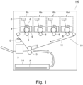
- An image forming apparatus 100 includes, as shown in Figure 1 , an image forming engine 10 of a so-called intermediary tandem type in which four image forming stations Pa, Pb, Pc and Pd and an intermediary transfer belt 11 are provided inside an apparatus main assembly.
- the image forming apparatus 100 forms and outputs an image on a recording material P on the basis of image information read from an original or image information inputted from an external device.
- the recording material P includes, in addition to plain paper, special paper such as coated paper, paper having a special shape such as an envelope or index paper, a plastic film for an overhead projector, and a cloth, and the like.
- the image forming stations Pa - Pd which are image forming units of an electrophotographic type includes photosensitive drums 1 as image bearing members, respectively, and form toner images of yellow, magenta, cyan and black on surfaces of the photosensitive drums 1 on the basis of image information. Structures of the respective image forming stations are substantially the same, and therefore, a unit structure will be described by taking the yellow image forming station Pa as an example.
- the charging device 2 electrically charges the surface of the photosensitive drum 1 uniformly by proximity discharge or corona discharge under application of a bias voltage from a high-voltage substrate mounted in the image forming apparatus.
- the exposure device 3 irradiate the charged surface of the photosensitive drum 1 with light based on the image information and exposes the photosensitive drum surface to the liquid, so that an electrostatic latent image is formed on the drum surface.
- the exposure device 3 includes a light source device and a polygonal mirror, and laser light emitted from the light source device is subjected to scanning by rotating the polygonal mirror, and a light flux of scanning light thereof is deflected by a plurality of reflection mirrors and concentrated on generatrix of the photosensitive drum 1 by an f ⁇ lens, and thus performs exposure of the drum surface to light.
- the developing device 4 includes a developing roller 41 as a developer carrying member, and develops the electrostatic latent image in a developing portion Gd formed between the developing roller 41 and the photosensitive drum 1.
- the developing device 4 in this embodiment is of a so-called liquid development type (wet development type) in which a liquid developer in which toner particles are dispersed in a carrier liquid is used, and the developing roller 41 rotates in a state in which the developing roller 41 carries the liquid developer on an outer peripheral surface.
- the developing device 4 supplies the toner particles to the photosensitive drum 1 by applying a bias voltage to the developing roller 41 and visualizes the electrostatic latent image into a toner image.
- a detailed structure of the developing device 4 will be described later.
- the toner image carried on the surface of the photosensitive drum 1 is primary-transferred onto the intermediary transfer belt 11 by the primary transfer roller 6 as a transfer device.
- the primary transfer roller 6 rotates in a direction, in which the primary transfer roller 6 is taken and rotated by the intermediary transfer belt 11, in a state in which the primary transfer roller 6 contacts an inner peripheral surface of the intermediary transfer belt 11, and to which a bias voltage opposite in polarity to a charge polarity of the toner particles, whereby the toner particles are subjected to electrophoresis toward the intermediary transfer belt 11.
- the toner images formed by the respective image forming stations Pa - Pd are multi-transferred so as to be superposed on each other, so that a full-color toner image is formed on the surface of the intermediary transfer belt 11.
- a deposited matter such as primary transfer residual toner remaining on the photosensitive drum 1 without being transferred on the intermediary transfer belt 11 is collected by the cleaning device 5.
- the cleaning device 5 includes a cleaning blade for scraping off the deposited matter together with the carrier liquid from the photosensitive drum and includes a pipe 52 for collecting the liquid developer scraped off.
- the intermediary transfer belt 11 as an intermediary transfer member is wound around the four primary transfer rollers 6, a secondary transfer inner roller 12, a driving roller, a tension roller and the like, and rotates in a predetermined direction (clockwise direction in the figure) along a feeding direction of the recording material P.
- a secondary transfer roller 13 opposing the secondary transfer inner roller 12 is provided on an outer periphery side of the intermediary transfer belt 11, as a secondary transfer device.
- the toner images transferred on the intermediary transfer belt 11 by the above-described image forming stations Pa - Pd are secondary-transferred onto the recording material P by a bias voltage applied to the secondary transfer roller 13.
- the recording material P is accommodated in a feeding cassette 14 and is fed toward the secondary transfer roller 13 with progress of toner image formation by the image forming stations Pa - Pd. Further, a deposited matter such as secondary transfer residual toner remaining on the intermediary transfer belt 11 without being transferred onto the recording material P is collected by a cleaning device 15.
- the recording material P on which the toner image is transferred is conveyed to a fixing portion 9 and is subjected to a predetermined fixing process of a heat fixing type or a photo-curing type or the like by the fixing portion 9, and thereafter is discharged to an outside of the apparatus.
- the photosensitive drum 1 one in which a photosensitive layer of an amorphous silicon type is provided on a rigid base layer member such as aluminum and preferably thereon, a protective layer comprising a silicone-based resin material is formed is used.
- the photosensitive drum 1 in this embodiment is used in a state in which the photosensitive drum 1 is charged to the negative polarity and for example, a surface potential (dark-portion potential) after the photosensitive drum 1 is charged by the charging device 2 is set at -600 [V], and a surface potential (light-portion potential) after the photosensitive drum 1 is exposed to light by the exposure device 3 is set at -200 [V].
- Entirety of the photosensitive drum 1 is constituted in an outer diameter of 100 mm, and is rotationally driven about a center line of a cylindrical shape as a rotational axis in an arrow R1 direction at a process speed (peripheral speed) of 500 mm/sec by a driving force supplied from a driving source such as a motor. Further, as regards productivity, the image forming apparatus is capable of performing a sheet passing of 100 sheets per minute in terms of A4(-size) sheets. Incidentally, the cylinder made of aluminum which is an inner periphery portion of the photosensitive drum is grounded.
- the bias voltage applied to the primary transfer roller 6 is +400 [V], and an outer diameter of a primary transfer roller 6 is 20 mm.
- the primary transfer roller 6 has a structure in which an outer periphery portion of a core shaft of stainless steel is covered with an elastic member such as a rubber, for example.
- a cleaning blade 51 is bonded at a part thereof to a metal plate, and the metal plate is fixed to a frame of the image forming station Pa by a rail-shaped member (not shown) and is press-contacted to the photosensitive drum 1. Further, the cleaning blade 51 has a certain size with respect to a longitudinal direction (axial direction of the photosensitive drum 1) and is 2.0 mm in thickness and 10 mm in free length which is a length from a portion covered with the metal plate portion to a free end.
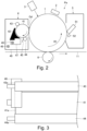
- the developing device 4 includes the developing roller 41, a developing container 40, a supply tray 47, an electrode member 42, a squeeze roller 43, a cleaning roller 44 and a cleaning blade 45.
- a developing liquid a liquid developer (hereinafter, referred to as a "developing liquid")
- a supply pipe 48 which is an inlet path of the developing liquid and a collection pipe 49 which is an outlet path of the develop are connected.
- the supply pipe 48 and the collecting pipe 49 are connected to an unshown mixer for temporarily store the developing liquid.
- the developing liquid collected from the collection pipe 49 and the toner and the carrier which are to be newly replenished are stirred and thus are uniformly mixed, so that the developing liquid in a state in which the developing liquid is adjusted to a proper concentration is supplied to the developing container 40 via the supply pipe 48.
- the developing liquid discharged from the supply pipe 48 is stored in the supply tray 47 inside the developing container 40.
- the supply tray 47 as a supply portion supplies the developing liquid to an outer peripheral surface of the developing roller 41 with rotation of the developing roller 41.
- the developing liquid carried on the predetermined 41 enters a gap between the developing roller 41 and the electrode member 42, the toner are electrophoretically moved toward the developing roller 41 by a bias voltage of the negative polarity applied to the electrode member 42.
- a layer in which the toner is concentrated in the neighborhood of the outer peripheral surface of the developing roller 41.
- the bias voltage applied to the developing roller 41 is set at -400 [V]
- the bias voltage applied to the electrode member 42 is set at -1000 [V].
- the developing device is constituted so that a gap between the developing roller 41 and the electrode is 500 ⁇ m, an outer diameter of the developing roller is 50 mm, and a section in which the developing roller 41 and the electrode member 42 oppose each other corresponds to an angle of rotation of 70° with respect to a rotational axis of the developing roller 41.
- the squeeze roller 43 is disposed downstream of the electrode member 42 and upstream of the developing portion Gd with respect to the rotational direction of the developing roller 41, and regulates a liquid amount of the developing liquid reaching the developing portion Gd.
- the squeeze roller 43 is rotational driven in a state in which the squeeze roller 43 is contacted to the developing roller 41 with a certain pressure. Further, also to the squeeze roller 43, the bias voltage is applied, so that the toner particles are further pushed toward the developing roller 41 by an electric field generating in a nip between the squeeze roller 43 and the developing roller 41.
- the toner in the developing liquid is further pushed toward the developing roller side, so that a developing liquid layer having a high density (concentration) and a uniform height is formed on the surface of the developing roller 41.
- an excessive carrier liquid removed from the toner by the squeeze roller 43 passes through an upper surface of the electrode member 42 and drops on a bottom of the developing container 40, and is collected to the mixer through the collection pipe 49.
- the bias applied to the squeeze roller 43 is -400 [V], and an outer diameter of the squeeze roller 43 is set at 15 mm.
- the squeeze roller 43 is an example of a liquid amount regulating member, and for example, a blade-like liquid amount regulating member may also be used.
- the toner particles electrophoretically moves toward the photosensitive drum 1.
- mobility of the toner particles is determined depending on the surface potential of the photosensitive drum 1, so that the toner particles are deposited on a region of the photosensitive drum 1 in which the electrostatic latent image is formed.
- the electrostatic latent image is visualized as the toner image.
- the surface of the photosensitive drum 1 passes through the developing portion Gd and separates from the developing roller 41, a part of the carrier liquid moves to the photosensitive drum 1, so that a state in which the surface of the photosensitive drum 1 is covered with the carrier liquid is formed.
- the developing liquid which did not move to the photosensitive drum 1 reaches the cleaning roller 44 positioned downstream the developing portion Gd with respect to the rotational direction of the developing roller 41.
- the cleaning roller 44 rotates in a state in which the cleaning roller 44 contacts the developing roller 41 with a certain contact pressure.
- the bias voltage is applied, and the toner particles remaining on the surface of the developing roller 41 are pulled out of the developing roller 41, and is electrically attracted to the cleaning roller 44.
- the developing liquid moved to the cleaning roller 44 is further pulled off of the cleaning roller 44 by the cleaning blade 45 and drops on the bottom of the developing container 40, and is collected to the mixer through the collection pipe 49.
- the bias voltage such that a potential on the basis of the developing roller 41 is +200 [V] is applied.
- the cleaning blade 45 is constituted so as to have the same potential as the cleaning roller 44.
- a surface layer of the developing roller 41 is a rubber such as urethane (rubber), and surface roughness Rz is defined as 5 ⁇ m or less in an initial condition.
- the electrode member 42, the squeeze roller 43, the cleaning roller 44 and the cleaning blade 45 are constituted by stainless steel (SUS). Surface roughness Rz of each of the electrode member 42, the squeeze roller 43 and the cleaning roller 44 is defined as a 1 ⁇ m or less.
- the toner particles are those in which colorant particles are incorporated in a binder resin material, and as the binder resin material, for example, it is possible to cite polyester resin material, epoxy resin material, styrene-acrylic resin material and the like.
- the colorant particles used in the toner particles it is possible to use general-purpose organic or inorganic pigments.
- Content of a colorant in the toner particles may preferably be 5 wt. parts or more and 100 wt. parts or less per 100 wt. parts of the binder resin material.
- pigments for black carbon black can be cited. Further, as pigments assuming blue or cyan, it is possible to cite the following pigments: C.I. Pigment Blue 2, 3, 15:2, 15::3, 15:4, 16, 17; C.I. Bat Blue 6; C.I. Acid Blue 45, and a copper phthalocyanine pigment having a phthalocyanine skeleton replaced by one to five phthalimidemethyl groups.
- the toner particles may preferably contain a pigment dispersant.
- a dispersing assistant synergists corresponding to various pigments are also capable of being used. Contents of preferred pigment dispersant and preferred pigment dispersing assistant are 0.01 to 50 wt. % in the toner particles.
- the pigment dispersant a known pigment dispersant can be used, and for example, as the dispersant, it is possible to cite hydroxyl group-containing carboxylate, a salt of long-chain polyaminoamide and a polymeric acid ester, a salt of a polycarboxylic acid, a polymeric unsaturated acid ester, a copolymer, a modified polyacrylate, an aliphatic polycarboxylic acid, a naphthalene sulfonic acid formalin condensate, a polyoxyethylene alkyl phosphate, a pigment derivative, and the like. Further, it is possible to cite a commercially available polymeric dispersant such as "Solsperse series", manufactured by Lubrizol Corp.
- An energy curable liquid used as the carrier liquid may preferably contain a charge control agent for imparting electric charges to the toner particle surfaces, a photo-polymerization initiator for generating acid by ultraviolet (UV) irradiation and a monomer bondable by the acid.
- the monomer bondable by the acid may preferably be a vinyl ether compound which is polymerizable by a cationic polymerization reaction.
- the energy curable liquid may further contain a sensitizer.
- a cationic polymerization inhibitor may preferably be contained in an amount of 10 - 5000 ppm on a weight basis of the energy curable liquid.
- a charge control aid, another additive or the like may also be contained in the energy curable liquid.
- the monomer (cationic polymerizable monomer), UV curing agent contained in the energy curable liquid is a mixture of a monofunctional monomer having one vinyl either group (represented by the following chemical formula (Chem 1)) and a difunctional monomer having two vinyl ether groups (represented by the following chemical formula (Chem 2)).
- the photo-polymerization initiator contained in the energy curable liquid is a compound represented by the following chemical formula (Chem 3) as a general formula.
- Chem 3 The photo-polymerization initiator contained in the energy curable liquid is a compound represented by the following chemical formula (Chem 3) as a general formula.
- R1 and R2 connect with each other and form a ring structure.
- x represents an integer of 1 - 8
- y represents an integer of 3 - 17.
- ring structure it is possible to exemplify a five-membered ring or a six-membered ring.
- a succinimide structure a phthalimide structure, a norbornene dicarboxylimide structure, a naphthalene decarboxyimide structure, a cyclohexane dicarboxyimide structure, an epoxycyclohexene dicarboxyimide structure, and the like.
- these ring structures may also include, as substituents, alkyl groups of 1 - 4 in carbon number, alkyloxy groups of 1 - 4 in carbon number, alkylthio groups of 1 - 4 in carbon number, aryl groups of 6 - 10 in carbon number, aryloxy groups of 6 - 10 in carbon number, arylthio groups of 6 - 10 in carbon number, and the like groups.
- C x F y in the chemical formula (Chem 3) it is possible to cite a linear alkyl group (RF1), a branched-chain alkyl group (RF2), a cycloalkyl group (RF3) and an aryl group (RF4), in which hydrogen atom is replaced with fluorine atom.
- RF1 linear alkyl group
- RF2 branched-chain alkyl group
- RF3 cycloalkyl group
- RF4 aryl group
- the content of the photo-polymerization initiator is not particularly limited, but may preferably be 0.01 - 5 wt. parts per 100 wt. parts of the cationic polymerizable monomer (preferably a vinyl ether compound).
- a compound represented by the following chemical formula (Chum 4) is contained in an amount of 0.3 wt. % per a total weight of the above-described monomer (cationic polymerizable monomer, UV-curable agent).
- the above-described cationic polymerizable monomer may desirably be at least one kind of a compound selected from the group consisting of dodecyl vinyl either, dipropylene glycol divinyl ether, dicyclopendadiene vinyl ether, cyclohexanedimethanol divinyl ether, tricyclodecane vinyl ether, trimethylolpropane trivinyl ether, 2-ethyl-1,3-hexamediol divinyl ether, 2,4-diethyl-1,5-pentanediol divinyl ether, 2-butyl-2-ethyl-1,3-propanediol divinyl ether, neopentylglycol divinyl ether, pentaerythritol tetravinyl ether, and 1,2-decanediol divinyl ether.
- dodecyl vinyl either, dipropylene glycol divinyl ether, dicyclopendad
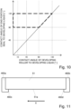
- Figure 3 is a schematic view showing a positional relationship among one end portions 41a, 43a and 44a of the developing roller 41, the squeeze roller 43 and the cleaning roller 44 with respect to the longitudinal direction, and other end portions are also constituted symmetrically with this positional relationship.
- a "length" refers to a length in the above-described longitudinal direction unless otherwise specified.
- an image formable region i.e., a maximum width of an image capable of being formed on the recording material P is 340 mm.
- a length of the developing roller 41 is 350 mm, and lengths of the squeeze roller 43, the cleaning roller 44 and the electrode member 42 are 356 mm.
- These members (41 - 44) are disposed so that center positions with respect to the longitudinal direction are aligned with each other.
- a length (length in the axial direction) of the photosensitive drum is 390 mm, and opposes an entire region of an outer peripheral surface of the developing roller 41 with respect to the longitudinal direction.
- the cleaning blade 51 (see Figure 2 ) for cleaning the photosensitive drum is 380 mm in length, and covers an entirety of a region in which the developing liquid is deposited from the developing roller 41 on the photosensitive drum 1. Further, a width of the intermediary transfer belt 11 (see Figure 1 ) is 365 mm, and is set so as to be shorter than the length of the photosensitive drum 1 in the axial direction. Further, the length of the secondary transfer roller 13 in the axial direction is 360 mm.
- the electrode member 42 is equal in length to the squeeze roller 43 and the cleaning roller 44, but may also have a constitution in which the length thereof is short compared with the length of these rollers.
- a liquid cross-linking phenomenon between the developing roller 41 and the end portion seal is capable of occurring even in the case where the electrode member 42 is short. That is because the developing liquid which passes through a gap between the electrode member 42 and the developing roller 41 and which enters a nip of the squeeze roller 43 is extended in the longitudinal direction when a thickness of the developing liquid is regulated by the squeeze roller 43.
- a gap (electrode gap) between the electrode member 42 and the developing roller 41 is about 500 ⁇ m, the developing liquid after passing through the squeeze roller 43 is regulated to a thickness of about 4 ⁇ m or less. For this reason, if the electrode member 42 is shortened, the developing liquid in a large amount extends toward the end portion with respect to the longitudinal direction due to a difference between a width of the above-described electrode gap and a regulation thickness by the squeeze roller 43.
- the developing roller 41 is short (in length) compared with the photosensitive drum 1. This is because in general, the photosensitive layer exposes on an end surface of the photosensitive drum 1 with respect to the axial direction and there is a possibility that current leakage occurs between the developing roller 41 and the photosensitive drum and has the influence on a development result.
- end portion seals 46 are provided at end portions of the developing roller 41 on opposite sides with respect to the longitudinal direction.
- the end portion seals 46 restrict movement of the developing liquid to an outside than a carrying surface of the developing roller 41 with respect to the longitudinal direction.
- the carrying surface of the developing roller 41 is a region where of an outer peripheral surface 41b, the developing liquid reaches the developing portion Gd in a state in which the developing liquid is carried by the developing roller 41, and in this embodiment, an entire region of the outer peripheral surface 41b in the longitudinal direction corresponds to the carrying surface.
- a range in which the end portion seal 46 covers the developing roller 41 extends from a position where the end portion seal 46 overlaps with the electrode member 42 with respect to the rotational direction of the developing roller 41 to a position downstream of the squeeze roller 43 after passing through the nip of the squeeze roller 43.
- the end portion seal 46 restricts deposition of the developing liquid, stored in the supply tray 47, on the end portion of the developing roller 41. Further, the end portion seal 46 restricts deposition of the developing liquid, squeezed by the squeeze roller 43, on the end portion of the developing roller 41.
- the end portion seal 46 may desirably extend to a position close to the developing portion Gd with respect to the rotational direction of the developing roller 41 to the extent possible.
- an angle ⁇ 1 between an end portion of the end portion seal 46 and the developing portion Gd with respect to the rotational direction of the developing roller 41 was about 40°.
- an angle of rotation from an end portion position of the end portion seal 46 on a position of the outer peripheral surface 41b of the developing roller 41 to a rectilinear line connecting rotational axes O1 and O2 of the developing roller 41 and the photosensitive drum 1 is about 40°.
- the end portion seal 46 has a restricting surface 46b contacting the end portion 41a of the developing roller 41.
- the restricting surface 46b contacts an edge portion 41c of the outer peripheral surface 41b of the developing roller 41 with respect to the longitudinal direction and extends substantially perpendicular to the axis of the developing roller 41 toward an outside than the outer peripheral surface 41b with respect to a radial direction.
- the developing liquid carried on the outer peripheral surface 41b which is the carrying surface is restricted in that the developing liquid reaches the end portion 41a of the developing roller 41 by moving around the edge portion 41c in a range in which at least the restricting surface 46b is disposed.
- the outer peripheral surface 41b of the developing roller 41 is in a state in which the outer peripheral surface 41b is coated with the developing liquid having a liquid surface with a certain height h0.
- the developing liquid is in a state in which the developing liquid contacts the restricting surface 46b of the end portion seal 46.
- the restricting surface 46b With higher wettability of the restricting surface 46b to a state such that the developing liquid runs up onto the restricting surface 46b toward a direction of being move away from the outer peripheral surface 41b of the developing roller 41 is formed (see broken line).
- liquid cross-linking by the developing liquid occurs between the restricting surface 46b of the end portion seal 46 and the outer peripheral surface 41b of the developing roller 41, so that a state in which the developing liquid accumulates in the neighborhood of the edge portion 41c is formed in some instances.
- the developing roller 41 When the developing roller 41 is rotated in the state in which such liquid cross-linking occurs, the developing liquid in a large amount deposits in the neighborhood of the edge portion 41c during separation of the outer peripheral surface 41b of the developing roller 41 from the restricting surface 46b. That is, a part of the developing liquid which has formed the liquid cross-linking moves to the developing roller 41, whereby the developing liquid in a large amount compared with the liquid amount with a height h0 of the developing liquid regulated by the squeeze roller deposits.
- the dark-portion potential of the photosensitive drum was -600 [V]
- the bias voltage applied to the developing roller was -400 [V].
- an electrostatic bias (fog-removing bias) in a direction toward the developing roller acts with electric field intensity equivalent to application of a DC voltage of 200 [V] to the developing roller on the basis of the surface potential of the photosensitive drum.
- electric field separation is carried out so that the toner particles contained in the developing liquid are pressed against the developing roller, so that deposition of the toner particles on the white background portion is prevented.
- the contact angle is defined by an angle formed, when a solid surface contacts a liquid and gas, by a liquid surface with the solid surface in a boundary line where the three phases contact each other. That is, as shown in Figure 7 , an angle ⁇ formed between the liquid surface and a solid surface S1 in an end portion of a droplet deposited on the solid surface S1 is the contact angle.
- the contact angle of the developing liquid to the restricting surface 46b of the end portion seal 46 is a magnitude of an angle formed between the restricting surface 46b and the liquid surface of the developing liquid contacting the restricting surface 46b as seen from a direction (a direction of tangential line of the outer peripheral surface 41b of the developing roller 41) parallel to the restricting surface 46b.
- the case where the contact angle of the developing liquid to the restricting surface 46b is less than 45° (broken line) and the case where the contact angle is about 90° (solid line) are shown.
- the contact angle of the developing liquid to the member constituting the end portion seal 46 was acquired by the following measuring method.
- a contact angle meter PCA-11 manufactured by Kyowa Interface Science Co., Ltd. is used.
- a droplet image acquired from a mounted camera is subjected to image analysis by an image analyzing software FAMAS (manufactured by Kyowa Interface Science Co., Ltd.) corresponding to the above-described PCA-11, so that the contact angle at 1 sec of contact is calculated through image processing.
- FAMAS image analyzing software
- the developing liquid in the mixer was used.
- a droplet of 1.0 uL (in volume) was formed by injecting the droplet of the developing liquid through an injection needle of 1.0 mm in injection diameter. This is contacted to an object-to-be-measured, and by the above-described image analyzing software, the contact angle at 1 sec of contact was calculated.
- a measuring operation was performed at room temperature. Incidentally, it has been known that an inner temperature of the developing container in the case where the image forming apparatus of this embodiment carries out the image forming operation is the same as the room temperature and is roughly in a range of 25°C - 35°C.
- Hardness of the end portion seal 46 may preferably be in a range of 40° or more and 60° or less in terms of Asker-C, and is 50°, for example.
- a lower limit of the hardness is determined in consideration of an entering (penetration) amount described later. Further, there is a possibility of breakage due to settling in the case where the hardness is low, and there is a possibility of deterioration and breakage or the like of a developing roller end portion due to wearing in the case where the hardness is high, and therefore, a preferred range of the hardness is set in consideration of such factors and the material of the developing roller.
- surface roughness of the end portion seal 46 it is desirable that surface roughness Rz is 20 ⁇ m or less in the case where the end portion seal 46 is the flat plate-like rubber, and a cell diameter is 200 ⁇ m or less in the case where the end portion seal 46 is the foam sponge. This is because in the case where the roughness is excessively large, the developing liquid is trapped by the surface of the end portion seal 46 and irrespective of occurrence or non-occurrence of the liquid cross-linking, the developing liquid in an amount in which the developing liquid cannot be separated by the electric field is supplied to the developing roller with rotational drive of the developing roller in some instances.
- the entering amount is excessively large, the amount of the developing liquid carried by the end portion 41a can be decreased, but friction generating between the end portion 41a of the developing roller and the end portion seal 46 increases. In this case, there is a possibility that inclusion of a foreign matter into the developing liquid and destability of a driving speed of the developing roller 41 due to deterioration and breakage of the end portion 41b of the developing roller 41 and the end portion seal 46 are invited. In consideration of these factors, the entering amount is suitable when being set in a range of about 0.7 ⁇ 0.4 mm.
- the hardness of the developing roller is 25° or more and 50° or less in terms of Asker-C.
- Upper and lower limits of the hardness of the developing roller are set principally in consideration of efficiency of a developing process. That is, the upper and lower limits the developing roller hardness are set so that a sufficient width nip is formed between the developing roller and the photosensitive drum 1 in the developing portion Gd (see Figure 4 ) and thus the electric field separation is sufficiently carried out in the developing portion Gd, i.e., so that the toner in the developing liquid electrophoretically moves depending on the surface potential of the photosensitive drum 1 before the toner passes through and comes out of the nip.
- the outer peripheral surface of the developing roller passes through the electrode gap and the nip of the squeeze roller, the outer peripheral surface of the developing roller does not readily hold the layer of the developing liquid, so that there is a possibility that a distribution of a so-called (toner) application amount becomes unstable such that coating with the developing liquid is lost in a part of a region.
- the squeeze roller is constituted by, for example, a cylindrical stainless steel (SUS) of 15 mm in diameter.
- the surface roughness Rz of the squeeze roller may desirably be 0.1 ⁇ m or less.
- An entering amount of the end portion seal 46 into the squeeze roller may preferably be, for example, 0.7 mm.
- the squeeze roller is a smooth metal, and there a possibility of slip-through of the liquid developer due to settling, deterioration and the like of the end portion seal is small even when the end portion seal strongly contacts the squeeze roller and the influence of the squeeze roller on a rotation load is small, and therefore, the entering amount may also be 0.7 mm or more.
- the contact angle of the squeeze roller to the developing liquid it is desirable that the contact angle is equal to or larger than the contact angle of the developing roller and is smaller than the contact angle of the end portion seal.
- the contact angle of the squeeze roller to the dodecyl vinyl either is 10°.
- the restricting surface is a side surface on the developing liquid side where the end portion seal is supported by the developing roller.
- the contact angle between the developing liquid and the end portion seal is constituted so as to be larger than the developing liquid and the developing roller.
- Preferred ranges of the contact angles (of the developing liquid) to the end portion seal and the developing roller are shown in Figure 8 to Figure 10 .
- Figure 8 shows an example of a preferred range of the contact angle
- Figure 9 shows a more preferred range
- Figure 10 shows a further preferred range.
- the contact angle between the developing liquid and the end portion seal is regarded as being larger than the contact angle between the developing liquid and the developing roller (region on a side above a diagonal line). Further, when wettability of the end portion seal is very large (when the contact angle is small), the developing liquid is attracted to the end portion seal irrespective of the contact angle of the developing roller to the developing liquid, and therefore, the contact angle between the developing liquid and the end portion seal may preferably be 15° or more.
- the contact angle between the developing liquid and the end portion seal may more preferably be 45° or more.
- the Young's formula is the following formula (1) held by a balance of surface tension when the contact angle is ⁇ , y LG is surface tension acting on liquid-gas interface, ySL is surface tension acting on liquid-solid interface, and ySG is surface tension acting on solid-gas interface (see Figure 7 ).
- ⁇ SG ⁇ LG ⁇ cos ⁇ + ⁇ SL
- the surface tension ⁇ LG of the developing liquid in the structural example of this embodiment was 22 [mN/m] as an empirically acquired value.
- the contact angle ⁇ at this time was 45°.
- ySL was 14 [mN/m].
- resultant ySG was about 30 [mN/m].
- the developing liquid is pulled downward by gravitation, but in the liquid with a height of about several ⁇ m, dominant force is not the gravitation, but is the surface tension.
- the height of the developing liquid with respect to the outer peripheral surface of the developing roller i.e., a thickness of the developing liquid regulated by the squeeze roller is 2.5 ⁇ m
- the height of the developing liquid is a value different from 2.5 ⁇ m, so that the developing liquid becomes thicker with a smaller contact angle ⁇ . It is assumed that the developing liquid carried in a range of 2.5 ⁇ m from the edge portion of the developing roller with respect to the longitudinal direction is substantially divided equally into portions on the end portion seal and the developing roller with rotation of the developing roller.
- the contact angle ⁇ is 45°
- the height of the developing liquid carried on the surface of the developing roller after the developing liquid is separated from the end portion seal is roughly 2.5 ⁇ m, so that the height of the developing liquid entering the developing portion becomes substantially uniform with respect to the longitudinal direction.
- the contact angle between the end portion seal and the developing liquid 45° or more uniformity of the height of the developing liquid entering the developing portion is enhanced, so that the fog image can be effectively reduced.
- a difference in wettability to the developing liquid becomes large between the developing roller, required that the contact angle to the developing liquid is small (for example 30° or less), and the end portion seal.
- the contact angle between the developing liquid and the end portion seal is further preferably 90° or more.
- the liquid surface of the developing liquid is in a state in which the developing liquid surface contacts the restricting surface of the end portion seal 46 so as to be substantially perpendicular to the restricting surface 46b. That is, the developing liquid is repelled by the restricting surface 46b of the end portion seal 46, and therefore, the liquid cross-linking is not formed, so that the developing roller rotates in a state in which the height of the developing liquid is constant with respect to the longitudinal direction.
- the contact angle between the developing liquid and the end portion seal may preferably be 135° or less. This is because in the case where the contact angle is excessively large, there is a possibility that the developing liquid repelled from the restricting surface of the end portion seal drops and scatters into a periphery of the developing roller with the rotation of the developing roller and thus contaminates the photosensitive drum and the like.
- the present inventors determined an upper limit of the contact angle by model calculation using Furmidge equation relating to dynamic contact angle.
- the Furmidge equation is represented by the following formula (1).
- m is the mass (weight) of the droplet
- g is the acceleration of gravity [m/s 2 ]
- ⁇ is an angle of a slope along which the droplet descends [rad]
- ⁇ is a width of the droplet [m]
- ⁇ LG is the surface tension of the droplet [mN/m]
- ⁇ R is a receding contact angle of the droplet [rad]
- ⁇ A is an advancing contact angle of the droplet [rad].
- ⁇ LG is an empirically acquired value and is 22 [mN/m].
- the contact angle between the developing liquid and the developing roller is 15°. Further, a constitution in which during a period of the continuous image forming operation, the developing liquid is steadily supplied to the developing roller.
- the fog image generated immediately after the start of the image forming operation in the case where the contact angle between the developing liquid and the end portion seal is 10°, i.e., in the case where the contact angle between the developing liquid and the end portion seal is an angle smaller than the contact angle (15°) between the developing liquid and the developing roller.
- the fog image was suppressed at least until 30 minutes elapsed from the start of the continuous image forming operation.
- the fog image generated in the case where the image forming operation was carried out continuously for 2 hours or more, the fog image generated.
- the fog image was suppressed for 2 hours or more in the case where the contact angle between the developing liquid and the end portion seal is 45° and for 5 hours or more in the case where the contact angle is 90° or more. That is, it turned out that by setting the contact angle of the end portion seal to the developing liquid at 45° or more, preferably 90° or more, compared with the case where the contact angle of the end portion seal is simply larger than the contact angle of the developing roller, the fog image can be reduced even when the image forming apparatus is used continuously for a long time.
- the end portion seal having a large contact angle to the developing liquid compared with the outer peripheral surface of the developing roller is used.
- the end portion restricting member having a large contact angle to the developing liquid compared with the carrying surface of the developer carrying member is used.
- the end portion seal was constituted by the material having the lipophobic property, but the contact angle may also be adjusted by another method.
- the contact angle may also be increased by forming minute unevenness on the restricting surface of the end portion seal.
- the material of the end portion seal and the contents of the surface treatment, and the like may only be required to be changed.
- Figure 11 is a view of the cleaning blade as seen from right above the cleaning blade.
- the cleaning blade contacts the photosensitive drum 1 at an edge portion 51a and removes the developing liquid on the photosensitive drum 1.
- the end portion seal 460 is disposed in contact with the cleaning blade at each of opposite ends of the cleaning blade 51 with respect to a longitudinal direction X of the cleaning blade.
- Each end portion seal 460 has an L-shape so as to surround the end portion of the cleaning blade.
- the end portion seals 460 restrict the developing liquid by restricting surfaces 460c and 460d, respectively, so that the developing liquid removed by the edge portion 51a is not protruded from the cleaning blade.
- the restricting surfaces are side surfaces of the end portion seal positioned on a region side where the developing liquid on the cleaning blade is removed. Each of the restricting surfaces is positioned outside an image forming region with respect to the longitudinal direction X.
- Hardness of the end portion seal 460 may preferably be in a range of 40° or more and 60° or less in terms of Asker-C, and is 50°, for example.
- surface roughness of the end portion seal 460 it is desirable that surface roughness Rz is 20 ⁇ m or less in the case where the end portion seal 460 is the flat plate-like rubber, and a cell diameter is 200 ⁇ m or less in the case where the end portion seal 460 is the foam sponge.
- the end portion seal 460 is a foam sponge containing the fluorocarbon resin material and is 100 - 200 ⁇ m or less in cell diameter. Further, in the above-described contact angle meter, the droplet of 0.1 uL used in the measurement has a size of about 2.5 mm in diameter and has a size which is about 10 times or more the cell diameter. By this, even when there is a surface roughness of the end portion seal 460 due to the foam structure, it becomes possible to measure the contact angle macroscopically substantially equivalent to a measurement result for a solid member with no foam structure, so that measurement accuracy is ensured.
- the contact angle between the developing liquid and the restricting surface is set at 45° or more.
- a measuring method of the contact angle is similar to that in the above-described embodiment. Further, this effect is more preferred when the contact angle is made 90° or more, and is further improved when the contact angle is made 135° or more.
- the contact angle between the restricting surface and the developing liquid is larger than the contact angle between the cleaning blade and the developing liquid.
- the contact angle between the cleaning blade and the developing liquid is measured in the neighborhood (in a region within 10 mm from the edge portion) of the edge portion 51a.
- the constitution of the cleaning blade for cleaning the photosensitive drum 1 was employed, but the cleaning blade may also be a cleaning blade for cleaning an object in contact with the object. Further, in this embodiment, an elastic cleaning blade was used, but the material of the cleaning blade is not limited to this material. For example, in a constitution such that the developing liquid on a metal roller is removed in contact with the metal roller, a metal blade is used in some cases, and even when the end portion seal in this embodiment is also employed for this metal blade, a similar effect can be obtained
- the end portion seals provided for the developing roller and the cleaning blade were described. Even when the end portion seal in this embodiment is also used for the metal roller (holding roller) for carrying the developing liquid, it is possible to reduce leakage, to the outside, of the developing liquid by movement around the metal roller.
- the developing device capable of reducing movement of the developing liquid around the end portion with a simple constitution.
Landscapes
- Physics & Mathematics (AREA)
- General Physics & Mathematics (AREA)
- Wet Developing In Electrophotography (AREA)
- Cleaning In Electrography (AREA)
Claims (8)
- Dispositif de révélateur liquide comprenant :un récipient de révélation (40) accueillant un révélateur liquide ;un rouleau de maintien (41) destiné à maintenir le révélateur liquide accueilli dans ledit récipient de révélation (40) ; etun organe de restriction de partie d'extrémité (46), disposé en contact avec ledit rouleau de maintien (41) au niveau d'une partie d'extrémité dudit rouleau de maintien (41) par rapport à une direction longitudinale dudit rouleau de maintien (41), destiné à restreindre le mouvement du révélateur liquide dans la direction longitudinale,caractérisé en ce quel'organe de restriction de partie d'extrémité (46) est configuré de sorte qu'un angle de contact (θ) d'une surface latérale (46b) dudit organe de restriction de partie d'extrémité (46) sur un côté où ledit rouleau de maintien (41) maintient le révélateur liquide, par rapport au révélateur liquide soit de 45° ou plus,dans lequel l'angle de contact (θ) est l'angle de contact du révélateur liquide avec la surface latérale (46b) de l'organe de restriction de partie d'extrémité (46), qui est une grandeur d'un angle formé entre la surface latérale (46b) et la surface liquide du révélateur liquide en contact avec la surface latérale (46b), vu depuis une direction parallèle à la surface latérale (46b),dans lequel l'angle de contact (θ) entre le révélateur liquide et la surface latérale (46b) dudit organe de restriction de partie d'extrémité (46) sur un côté où ledit rouleau de maintien (41) maintient le révélateur liquide, est supérieur à un angle de contact entre le révélateur liquide et une surface portante du rouleau de maintien (41).
- Dispositif de révélateur liquide selon la revendication 1, dans lequelle rouleau de maintien est un organe de support de révélateur rotatif (41) destiné à supporter le révélateur liquide accueilli dans ledit récipient de révélation (40) pour la révélation d'une image latente électrostatique supportée sur un organe de support d'image (1), etl'organe de restriction de partie d'extrémité (46) est disposé en contact avec ledit organe de support de révélateur (41) au niveau d'une partie d'extrémité dudit organe de support de révélateur (41) par rapport à une direction d'axe de rotation dudit organe de support de révélateur (41), pour restreindre un mouvement du révélateur liquide dans la direction d'axe de rotation,caractérisé en ce que l'organe de restriction de partie d'extrémité (46) est configuré de sorte qu'un angle de contact d'une surface latérale (46b) dudit organe de restriction de partie d'extrémité (46) sur un côté où ledit organe de support de révélateur (41) supporte le révélateur liquide, par rapport au révélateur liquide est de 45° ou plus.
- Dispositif de révélateur liquide selon la revendication 2, dans lequel l'organe de restriction de partie d'extrémité (46) est configuré de sorte que l'angle de contact entre la surface latérale (46b) et le révélateur liquide est supérieur à un angle de contact entre la surface de support (41b) dudit organe de support de révélateur (41) et le révélateur liquide.
- Dispositif de révélateur liquide selon la revendication 2 ou 3, dans lequel l'organe de restriction de partie d'extrémité (46) est configuré de sorte que l'angle de contact entre la surface latérale (46b) et le révélateur liquide soit de 90° ou plus.
- Dispositif de révélateur liquide selon l'une quelconque des revendications 2 à 4, dans lequel l'organe de restriction de partie d'extrémité (46) est configuré de sorte que l'angle de contact entre la surface latérale (46b) et le révélateur liquide soit de 135° ou moins.
- Dispositif de révélateur liquide selon l'une quelconque des revendications 2 à 5, comprenant :une partie d'alimentation (47) pour l'alimentation en révélateur liquide accueilli dans ledit récipient de révélation (40) dudit organe de support de révélateur (41), etun organe de régulation de quantité de liquide (43), disposé en aval de ladite partie d'alimentation (47) par rapport à une direction de rotation et en amont d'une partie de révélation (Gd) où ledit organe de support de révélateur (41) s'oppose à l'organe de support d'image (1), pour la régulation d'une quantité du révélateur liquide qui est supportée sur ledit organe de support de révélateur (41) et qui atteint la partie de révélation (Gd).
- Dispositif de révélateur liquide selon l'une quelconque des revendications 1 à 6, dans lequel la surface latérale (46b) est un organe élastique contenant un matériau de résine fluorocarbonée ou une surface d'organe élastique revêtue du matériau de résine fluorocarbonée.
- Dispositif de révélateur liquide selon l'une quelconque des revendications 1 à 7, dans lequel un liquide porteur du révélateur liquide contient du dodécyl vinyl éther, et l'organe de restriction de partie d'extrémité (46) est configuré de sorte qu'un angle de contact entre ledit organe de restriction de partie d'extrémité (46) et le dodécyl vinyl éther soit supérieur à un angle de contact entre la surface de support (41b) dudit organe de support de révélateur (41) et le dodécyl vinyl éther.
Applications Claiming Priority (2)
| Application Number | Priority Date | Filing Date | Title |
|---|---|---|---|
| JP2017063729 | 2017-03-28 | ||
| PCT/JP2018/014346 WO2018182049A1 (fr) | 2017-03-28 | 2018-03-28 | Dispositif de développement, dispositif de nettoyage et dispositif de révélateur liquide |
Publications (3)
| Publication Number | Publication Date |
|---|---|
| EP3605242A1 EP3605242A1 (fr) | 2020-02-05 |
| EP3605242A4 EP3605242A4 (fr) | 2021-03-24 |
| EP3605242B1 true EP3605242B1 (fr) | 2025-05-07 |
Family
ID=63676666
Family Applications (1)
| Application Number | Title | Priority Date | Filing Date |
|---|---|---|---|
| EP18775000.5A Active EP3605242B1 (fr) | 2017-03-28 | 2018-03-28 | Dispositif de développement, dispositif de nettoyage et dispositif de révélateur liquide |
Country Status (4)
| Country | Link |
|---|---|
| US (1) | US11048188B2 (fr) |
| EP (1) | EP3605242B1 (fr) |
| JP (1) | JP2018165820A (fr) |
| WO (1) | WO2018182049A1 (fr) |
Families Citing this family (1)
| Publication number | Priority date | Publication date | Assignee | Title |
|---|---|---|---|---|
| JP2019012235A (ja) | 2017-06-30 | 2019-01-24 | キヤノン株式会社 | 現像装置 |
Family Cites Families (20)
| Publication number | Priority date | Publication date | Assignee | Title |
|---|---|---|---|---|
| JPS516733A (ja) * | 1974-07-09 | 1976-01-20 | Ricoh Kk | Genzoroorasochi |
| US4399933A (en) * | 1981-07-27 | 1983-08-23 | Xerox Corporation | Toner dispensing apparatus |
| JPH09225369A (ja) * | 1996-02-20 | 1997-09-02 | Ricoh Co Ltd | 液体付与装置、被記録材の前処理装置、被記録材の再生装置および湿式電子写真の現像装置 |
| JP2000047490A (ja) * | 1998-07-30 | 2000-02-18 | Ricoh Co Ltd | 液体現像装置 |
| JP2001051512A (ja) * | 1999-08-05 | 2001-02-23 | Matsushita Electric Ind Co Ltd | 現像装置 |
| JP2001272874A (ja) * | 2000-03-27 | 2001-10-05 | Ricoh Co Ltd | 画像形成装置の熱定着装置及びその画像定着方法 |
| JP4072589B2 (ja) * | 2000-06-07 | 2008-04-09 | シャープ株式会社 | 回転部材のシール構造 |
| KR100433543B1 (ko) * | 2002-02-07 | 2004-05-31 | 삼성전자주식회사 | 전자사진방식 화상형성장치의 현상장치 |
| JP4547165B2 (ja) * | 2004-02-27 | 2010-09-22 | 京セラミタ株式会社 | 液体画像形成装置のクリーニング装置 |
| JP2006085159A (ja) * | 2004-08-19 | 2006-03-30 | Pentax Corp | 湿式画像形成装置のクリーニング装置 |
| JP4499130B2 (ja) * | 2006-06-27 | 2010-07-07 | バンドー化学株式会社 | 液体現像電子写真装置用ローラー |
| JP4844529B2 (ja) * | 2007-10-16 | 2011-12-28 | コニカミノルタビジネステクノロジーズ株式会社 | 液体現像装置及び画像形成装置 |
| JP4991488B2 (ja) * | 2007-11-06 | 2012-08-01 | 京セラドキュメントソリューションズ株式会社 | 画像形成装置 |
| JP2009258609A (ja) * | 2008-03-21 | 2009-11-05 | Seiko Epson Corp | 現像装置、及び、画像形成装置 |
| JP2010096949A (ja) * | 2008-10-16 | 2010-04-30 | Seiko Epson Corp | クリーニング装置及び画像形成装置 |
| JP2010217689A (ja) * | 2009-03-18 | 2010-09-30 | Brother Ind Ltd | 現像装置 |
| JP2011022246A (ja) | 2009-07-14 | 2011-02-03 | Konica Minolta Holdings Inc | 画像形成装置 |
| WO2015116206A2 (fr) * | 2014-01-31 | 2015-08-06 | Hewlett-Packard Indigo B.V. | Unité de révélateur d'encre |
| JP6666038B2 (ja) * | 2015-05-27 | 2020-03-13 | キヤノン株式会社 | 液体現像剤 |
| JP6614807B2 (ja) * | 2015-05-28 | 2019-12-04 | キヤノン株式会社 | 画像形成装置 |
-
2018
- 2018-03-23 JP JP2018057008A patent/JP2018165820A/ja active Pending
- 2018-03-28 WO PCT/JP2018/014346 patent/WO2018182049A1/fr not_active Ceased
- 2018-03-28 EP EP18775000.5A patent/EP3605242B1/fr active Active
-
2019
- 2019-09-25 US US16/581,991 patent/US11048188B2/en active Active
Also Published As
| Publication number | Publication date |
|---|---|
| US20200019087A1 (en) | 2020-01-16 |
| JP2018165820A (ja) | 2018-10-25 |
| WO2018182049A1 (fr) | 2018-10-04 |
| EP3605242A1 (fr) | 2020-02-05 |
| US11048188B2 (en) | 2021-06-29 |
| EP3605242A4 (fr) | 2021-03-24 |
Similar Documents
| Publication | Publication Date | Title |
|---|---|---|
| US20080193178A1 (en) | Cleaning device, image forming apparatus, and process cartridge | |
| US20050180784A1 (en) | Developing apparatus, cartridge and image forming apparatus | |
| US10248043B2 (en) | Image forming apparatus that prevents toner charged with polarity opposite normal charging polarity from being collected | |
| JP2022107347A (ja) | クリーニングブレード、プロセスカートリッジおよび画像形成装置 | |
| US9116459B2 (en) | Electrophotographic image forming apparatus | |
| US11048188B2 (en) | Developing device having liquid developer movement restriction | |
| JP2007147917A (ja) | 潤滑剤塗布装置、プロセスカートリッジ、画像形成装置 | |
| US20080253811A1 (en) | Developing device, process unit, and image forming apparatus | |
| US9442418B2 (en) | Developing device, process cartridge and image forming apparatus | |
| JP4772589B2 (ja) | 画像形成装置及びこれに用いられる転写装置 | |
| JP7452215B2 (ja) | クリーニングブレード、プロセスカートリッジ、及び画像形成装置 | |
| US9395653B2 (en) | Wet-type developing device and wet-type image forming apparatus | |
| US10747146B2 (en) | Developing device with cleaning roller and cleaning blade | |
| US10719028B2 (en) | Process cartridge and image forming apparatus | |
| JP3813570B2 (ja) | 帯電部材及び画像形成装置 | |
| WO2018101484A1 (fr) | Appareil de formation d'image | |
| US10996590B2 (en) | Image forming apparatus with belt cleaning device | |
| WO2019087887A1 (fr) | Appareil de formation d'image | |
| JP5201866B2 (ja) | 現像装置 | |
| US10394165B2 (en) | Developing device carrying liquid developer | |
| WO2018101487A1 (fr) | Dispositif de formation d'image | |
| JP2016018079A (ja) | 画像形成装置 | |
| JP2009042667A (ja) | 液体現像装置及びこれを搭載した画像形成装置 | |
| US20170123345A1 (en) | Developing device, process cartridge, and image forming apparatus | |
| JP2002258619A (ja) | 湿式画像形成装置 |
Legal Events
| Date | Code | Title | Description |
|---|---|---|---|
| STAA | Information on the status of an ep patent application or granted ep patent |
Free format text: STATUS: THE INTERNATIONAL PUBLICATION HAS BEEN MADE |
|
| PUAI | Public reference made under article 153(3) epc to a published international application that has entered the european phase |
Free format text: ORIGINAL CODE: 0009012 |
|
| STAA | Information on the status of an ep patent application or granted ep patent |
Free format text: STATUS: REQUEST FOR EXAMINATION WAS MADE |
|
| 17P | Request for examination filed |
Effective date: 20191028 |
|
| AK | Designated contracting states |
Kind code of ref document: A1 Designated state(s): AL AT BE BG CH CY CZ DE DK EE ES FI FR GB GR HR HU IE IS IT LI LT LU LV MC MK MT NL NO PL PT RO RS SE SI SK SM TR |
|
| AX | Request for extension of the european patent |
Extension state: BA ME |
|
| RIN1 | Information on inventor provided before grant (corrected) |
Inventor name: NAGATA TEPPEI Inventor name: FUJIOKA RYOTA Inventor name: KOJIMA TAKEHIRO Inventor name: TAKAMI SHOTA |
|
| DAV | Request for validation of the european patent (deleted) | ||
| DAX | Request for extension of the european patent (deleted) | ||
| A4 | Supplementary search report drawn up and despatched |
Effective date: 20210224 |
|
| RIC1 | Information provided on ipc code assigned before grant |
Ipc: G03G 15/11 20060101ALI20210218BHEP Ipc: G03G 15/10 20060101AFI20210218BHEP Ipc: G03G 21/00 20060101ALI20210218BHEP |
|
| STAA | Information on the status of an ep patent application or granted ep patent |
Free format text: STATUS: EXAMINATION IS IN PROGRESS |
|
| 17Q | First examination report despatched |
Effective date: 20230328 |
|
| GRAP | Despatch of communication of intention to grant a patent |
Free format text: ORIGINAL CODE: EPIDOSNIGR1 |
|
| STAA | Information on the status of an ep patent application or granted ep patent |
Free format text: STATUS: GRANT OF PATENT IS INTENDED |
|
| INTG | Intention to grant announced |
Effective date: 20241203 |
|
| GRAS | Grant fee paid |
Free format text: ORIGINAL CODE: EPIDOSNIGR3 |
|
| GRAA | (expected) grant |
Free format text: ORIGINAL CODE: 0009210 |
|
| STAA | Information on the status of an ep patent application or granted ep patent |
Free format text: STATUS: THE PATENT HAS BEEN GRANTED |
|
| AK | Designated contracting states |
Kind code of ref document: B1 Designated state(s): AL AT BE BG CH CY CZ DE DK EE ES FI FR GB GR HR HU IE IS IT LI LT LU LV MC MK MT NL NO PL PT RO RS SE SI SK SM TR |
|
| REG | Reference to a national code |
Ref country code: GB Ref legal event code: FG4D |
|
| REG | Reference to a national code |
Ref country code: CH Ref legal event code: EP |
|
| REG | Reference to a national code |
Ref country code: DE Ref legal event code: R096 Ref document number: 602018081751 Country of ref document: DE |
|
| REG | Reference to a national code |
Ref country code: IE Ref legal event code: FG4D |
|
| REG | Reference to a national code |
Ref country code: NL Ref legal event code: MP Effective date: 20250507 |
|
| PG25 | Lapsed in a contracting state [announced via postgrant information from national office to epo] |
Ref country code: PT Free format text: LAPSE BECAUSE OF FAILURE TO SUBMIT A TRANSLATION OF THE DESCRIPTION OR TO PAY THE FEE WITHIN THE PRESCRIBED TIME-LIMIT Effective date: 20250908 Ref country code: ES Free format text: LAPSE BECAUSE OF FAILURE TO SUBMIT A TRANSLATION OF THE DESCRIPTION OR TO PAY THE FEE WITHIN THE PRESCRIBED TIME-LIMIT Effective date: 20250507 Ref country code: FI Free format text: LAPSE BECAUSE OF FAILURE TO SUBMIT A TRANSLATION OF THE DESCRIPTION OR TO PAY THE FEE WITHIN THE PRESCRIBED TIME-LIMIT Effective date: 20250507 |
|
| REG | Reference to a national code |
Ref country code: LT Ref legal event code: MG9D |
|
| PG25 | Lapsed in a contracting state [announced via postgrant information from national office to epo] |
Ref country code: GR Free format text: LAPSE BECAUSE OF FAILURE TO SUBMIT A TRANSLATION OF THE DESCRIPTION OR TO PAY THE FEE WITHIN THE PRESCRIBED TIME-LIMIT Effective date: 20250808 Ref country code: NO Free format text: LAPSE BECAUSE OF FAILURE TO SUBMIT A TRANSLATION OF THE DESCRIPTION OR TO PAY THE FEE WITHIN THE PRESCRIBED TIME-LIMIT Effective date: 20250807 |
|
| PG25 | Lapsed in a contracting state [announced via postgrant information from national office to epo] |
Ref country code: NL Free format text: LAPSE BECAUSE OF FAILURE TO SUBMIT A TRANSLATION OF THE DESCRIPTION OR TO PAY THE FEE WITHIN THE PRESCRIBED TIME-LIMIT Effective date: 20250507 Ref country code: PL Free format text: LAPSE BECAUSE OF FAILURE TO SUBMIT A TRANSLATION OF THE DESCRIPTION OR TO PAY THE FEE WITHIN THE PRESCRIBED TIME-LIMIT Effective date: 20250507 |
|
| REG | Reference to a national code |
Ref country code: AT Ref legal event code: MK05 Ref document number: 1793129 Country of ref document: AT Kind code of ref document: T Effective date: 20250507 |
|
| PG25 | Lapsed in a contracting state [announced via postgrant information from national office to epo] |
Ref country code: BG Free format text: LAPSE BECAUSE OF FAILURE TO SUBMIT A TRANSLATION OF THE DESCRIPTION OR TO PAY THE FEE WITHIN THE PRESCRIBED TIME-LIMIT Effective date: 20250507 |
|
| PG25 | Lapsed in a contracting state [announced via postgrant information from national office to epo] |
Ref country code: HR Free format text: LAPSE BECAUSE OF FAILURE TO SUBMIT A TRANSLATION OF THE DESCRIPTION OR TO PAY THE FEE WITHIN THE PRESCRIBED TIME-LIMIT Effective date: 20250507 |
|
| PG25 | Lapsed in a contracting state [announced via postgrant information from national office to epo] |
Ref country code: AT Free format text: LAPSE BECAUSE OF FAILURE TO SUBMIT A TRANSLATION OF THE DESCRIPTION OR TO PAY THE FEE WITHIN THE PRESCRIBED TIME-LIMIT Effective date: 20250507 |
|
| PG25 | Lapsed in a contracting state [announced via postgrant information from national office to epo] |
Ref country code: RS Free format text: LAPSE BECAUSE OF FAILURE TO SUBMIT A TRANSLATION OF THE DESCRIPTION OR TO PAY THE FEE WITHIN THE PRESCRIBED TIME-LIMIT Effective date: 20250807 |
|
| PG25 | Lapsed in a contracting state [announced via postgrant information from national office to epo] |
Ref country code: IS Free format text: LAPSE BECAUSE OF FAILURE TO SUBMIT A TRANSLATION OF THE DESCRIPTION OR TO PAY THE FEE WITHIN THE PRESCRIBED TIME-LIMIT Effective date: 20250907 |
|
| PG25 | Lapsed in a contracting state [announced via postgrant information from national office to epo] |
Ref country code: LV Free format text: LAPSE BECAUSE OF FAILURE TO SUBMIT A TRANSLATION OF THE DESCRIPTION OR TO PAY THE FEE WITHIN THE PRESCRIBED TIME-LIMIT Effective date: 20250507 |
|
| PG25 | Lapsed in a contracting state [announced via postgrant information from national office to epo] |
Ref country code: SM Free format text: LAPSE BECAUSE OF FAILURE TO SUBMIT A TRANSLATION OF THE DESCRIPTION OR TO PAY THE FEE WITHIN THE PRESCRIBED TIME-LIMIT Effective date: 20250507 Ref country code: DK Free format text: LAPSE BECAUSE OF FAILURE TO SUBMIT A TRANSLATION OF THE DESCRIPTION OR TO PAY THE FEE WITHIN THE PRESCRIBED TIME-LIMIT Effective date: 20250507 |
|
| PG25 | Lapsed in a contracting state [announced via postgrant information from national office to epo] |
Ref country code: CZ Free format text: LAPSE BECAUSE OF FAILURE TO SUBMIT A TRANSLATION OF THE DESCRIPTION OR TO PAY THE FEE WITHIN THE PRESCRIBED TIME-LIMIT Effective date: 20250507 |
|
| PG25 | Lapsed in a contracting state [announced via postgrant information from national office to epo] |
Ref country code: EE Free format text: LAPSE BECAUSE OF FAILURE TO SUBMIT A TRANSLATION OF THE DESCRIPTION OR TO PAY THE FEE WITHIN THE PRESCRIBED TIME-LIMIT Effective date: 20250507 |
|
| PG25 | Lapsed in a contracting state [announced via postgrant information from national office to epo] |
Ref country code: RO Free format text: LAPSE BECAUSE OF FAILURE TO SUBMIT A TRANSLATION OF THE DESCRIPTION OR TO PAY THE FEE WITHIN THE PRESCRIBED TIME-LIMIT Effective date: 20250507 Ref country code: SK Free format text: LAPSE BECAUSE OF FAILURE TO SUBMIT A TRANSLATION OF THE DESCRIPTION OR TO PAY THE FEE WITHIN THE PRESCRIBED TIME-LIMIT Effective date: 20250507 |
|
| PG25 | Lapsed in a contracting state [announced via postgrant information from national office to epo] |
Ref country code: IT Free format text: LAPSE BECAUSE OF FAILURE TO SUBMIT A TRANSLATION OF THE DESCRIPTION OR TO PAY THE FEE WITHIN THE PRESCRIBED TIME-LIMIT Effective date: 20250507 |
|
| REG | Reference to a national code |
Ref country code: DE Ref legal event code: R097 Ref document number: 602018081751 Country of ref document: DE |
|
| PLBE | No opposition filed within time limit |
Free format text: ORIGINAL CODE: 0009261 |
|
| STAA | Information on the status of an ep patent application or granted ep patent |
Free format text: STATUS: NO OPPOSITION FILED WITHIN TIME LIMIT |
|
| REG | Reference to a national code |
Ref country code: CH Ref legal event code: L10 Free format text: ST27 STATUS EVENT CODE: U-0-0-L10-L00 (AS PROVIDED BY THE NATIONAL OFFICE) Effective date: 20260318 |
|
| PGFP | Annual fee paid to national office [announced via postgrant information from national office to epo] |
Ref country code: GB Payment date: 20260219 Year of fee payment: 9 |
|
| 26N | No opposition filed |
Effective date: 20260210 |