EP3605268A1 - Boulon d'encliquetage à mécanique d'encliquetage protégée - Google Patents
Boulon d'encliquetage à mécanique d'encliquetage protégée Download PDFInfo
- Publication number
- EP3605268A1 EP3605268A1 EP19178332.3A EP19178332A EP3605268A1 EP 3605268 A1 EP3605268 A1 EP 3605268A1 EP 19178332 A EP19178332 A EP 19178332A EP 3605268 A1 EP3605268 A1 EP 3605268A1
- Authority
- EP
- European Patent Office
- Prior art keywords
- locking
- sleeve
- guide sleeve
- actuating button
- contour
- Prior art date
- Legal status (The legal status is an assumption and is not a legal conclusion. Google has not performed a legal analysis and makes no representation as to the accuracy of the status listed.)
- Granted
Links
Images




Classifications
-
- G—PHYSICS
- G05—CONTROLLING; REGULATING
- G05G—CONTROL DEVICES OR SYSTEMS INSOFAR AS CHARACTERISED BY MECHANICAL FEATURES ONLY
- G05G25/00—Other details or appurtenances of control mechanisms, e.g. supporting intermediate members elastically
- G05G25/04—Sealing against entry of dust, weather or the like
-
- F—MECHANICAL ENGINEERING; LIGHTING; HEATING; WEAPONS; BLASTING
- F16—ENGINEERING ELEMENTS AND UNITS; GENERAL MEASURES FOR PRODUCING AND MAINTAINING EFFECTIVE FUNCTIONING OF MACHINES OR INSTALLATIONS; THERMAL INSULATION IN GENERAL
- F16B—DEVICES FOR FASTENING OR SECURING CONSTRUCTIONAL ELEMENTS OR MACHINE PARTS TOGETHER, e.g. NAILS, BOLTS, CIRCLIPS, CLAMPS, CLIPS OR WEDGES; JOINTS OR JOINTING
- F16B21/00—Means for preventing relative axial movement of a pin, spigot, shaft or the like and a member surrounding it; Stud-and-socket releasable fastenings
- F16B21/10—Means for preventing relative axial movement of a pin, spigot, shaft or the like and a member surrounding it; Stud-and-socket releasable fastenings by separate parts
- F16B21/16—Means for preventing relative axial movement of a pin, spigot, shaft or the like and a member surrounding it; Stud-and-socket releasable fastenings by separate parts with grooves or notches in the pin or shaft
- F16B21/165—Means for preventing relative axial movement of a pin, spigot, shaft or the like and a member surrounding it; Stud-and-socket releasable fastenings by separate parts with grooves or notches in the pin or shaft with balls or rollers
-
- F—MECHANICAL ENGINEERING; LIGHTING; HEATING; WEAPONS; BLASTING
- F16—ENGINEERING ELEMENTS AND UNITS; GENERAL MEASURES FOR PRODUCING AND MAINTAINING EFFECTIVE FUNCTIONING OF MACHINES OR INSTALLATIONS; THERMAL INSULATION IN GENERAL
- F16B—DEVICES FOR FASTENING OR SECURING CONSTRUCTIONAL ELEMENTS OR MACHINE PARTS TOGETHER, e.g. NAILS, BOLTS, CIRCLIPS, CLAMPS, CLIPS OR WEDGES; JOINTS OR JOINTING
- F16B19/00—Bolts without screw-thread; Pins, including deformable elements; Rivets
- F16B19/04—Rivets; Spigots or the like fastened by riveting
- F16B19/08—Hollow rivets; Multi-part rivets
- F16B19/10—Hollow rivets; Multi-part rivets fastened by expanding mechanically
- F16B19/1027—Multi-part rivets
- F16B19/1036—Blind rivets
- F16B19/109—Temporary rivets, e.g. with a spring-loaded pin
-
- F—MECHANICAL ENGINEERING; LIGHTING; HEATING; WEAPONS; BLASTING
- F16—ENGINEERING ELEMENTS AND UNITS; GENERAL MEASURES FOR PRODUCING AND MAINTAINING EFFECTIVE FUNCTIONING OF MACHINES OR INSTALLATIONS; THERMAL INSULATION IN GENERAL
- F16B—DEVICES FOR FASTENING OR SECURING CONSTRUCTIONAL ELEMENTS OR MACHINE PARTS TOGETHER, e.g. NAILS, BOLTS, CIRCLIPS, CLAMPS, CLIPS OR WEDGES; JOINTS OR JOINTING
- F16B19/00—Bolts without screw-thread; Pins, including deformable elements; Rivets
- F16B19/02—Bolts or sleeves for positioning of machine parts, e.g. notched taper pins, fitting pins, sleeves, eccentric positioning rings
-
- F—MECHANICAL ENGINEERING; LIGHTING; HEATING; WEAPONS; BLASTING
- F16—ENGINEERING ELEMENTS AND UNITS; GENERAL MEASURES FOR PRODUCING AND MAINTAINING EFFECTIVE FUNCTIONING OF MACHINES OR INSTALLATIONS; THERMAL INSULATION IN GENERAL
- F16B—DEVICES FOR FASTENING OR SECURING CONSTRUCTIONAL ELEMENTS OR MACHINE PARTS TOGETHER, e.g. NAILS, BOLTS, CIRCLIPS, CLAMPS, CLIPS OR WEDGES; JOINTS OR JOINTING
- F16B21/00—Means for preventing relative axial movement of a pin, spigot, shaft or the like and a member surrounding it; Stud-and-socket releasable fastenings
- F16B21/02—Releasable fastening devices locking by rotation
-
- F—MECHANICAL ENGINEERING; LIGHTING; HEATING; WEAPONS; BLASTING
- F16—ENGINEERING ELEMENTS AND UNITS; GENERAL MEASURES FOR PRODUCING AND MAINTAINING EFFECTIVE FUNCTIONING OF MACHINES OR INSTALLATIONS; THERMAL INSULATION IN GENERAL
- F16B—DEVICES FOR FASTENING OR SECURING CONSTRUCTIONAL ELEMENTS OR MACHINE PARTS TOGETHER, e.g. NAILS, BOLTS, CIRCLIPS, CLAMPS, CLIPS OR WEDGES; JOINTS OR JOINTING
- F16B21/00—Means for preventing relative axial movement of a pin, spigot, shaft or the like and a member surrounding it; Stud-and-socket releasable fastenings
- F16B21/10—Means for preventing relative axial movement of a pin, spigot, shaft or the like and a member surrounding it; Stud-and-socket releasable fastenings by separate parts
- F16B21/16—Means for preventing relative axial movement of a pin, spigot, shaft or the like and a member surrounding it; Stud-and-socket releasable fastenings by separate parts with grooves or notches in the pin or shaft
-
- G—PHYSICS
- G05—CONTROLLING; REGULATING
- G05G—CONTROL DEVICES OR SYSTEMS INSOFAR AS CHARACTERISED BY MECHANICAL FEATURES ONLY
- G05G5/00—Means for preventing, limiting or returning the movements of parts of a control mechanism, e.g. locking controlling member
- G05G5/06—Means for preventing, limiting or returning the movements of parts of a control mechanism, e.g. locking controlling member for holding members in one or a limited number of definite positions only
-
- G—PHYSICS
- G05—CONTROLLING; REGULATING
- G05G—CONTROL DEVICES OR SYSTEMS INSOFAR AS CHARACTERISED BY MECHANICAL FEATURES ONLY
- G05G1/00—Controlling members, e.g. knobs or handles; Assemblies or arrangements thereof; Indicating position of controlling members
- G05G1/08—Controlling members for hand actuation by rotary movement, e.g. hand wheels
-
- Y—GENERAL TAGGING OF NEW TECHNOLOGICAL DEVELOPMENTS; GENERAL TAGGING OF CROSS-SECTIONAL TECHNOLOGIES SPANNING OVER SEVERAL SECTIONS OF THE IPC; TECHNICAL SUBJECTS COVERED BY FORMER USPC CROSS-REFERENCE ART COLLECTIONS [XRACs] AND DIGESTS
- Y10—TECHNICAL SUBJECTS COVERED BY FORMER USPC
- Y10T—TECHNICAL SUBJECTS COVERED BY FORMER US CLASSIFICATION
- Y10T403/00—Joints and connections
- Y10T403/59—Manually releaseable latch type
- Y10T403/598—Transversely sliding pin
-
- Y—GENERAL TAGGING OF NEW TECHNOLOGICAL DEVELOPMENTS; GENERAL TAGGING OF CROSS-SECTIONAL TECHNOLOGIES SPANNING OVER SEVERAL SECTIONS OF THE IPC; TECHNICAL SUBJECTS COVERED BY FORMER USPC CROSS-REFERENCE ART COLLECTIONS [XRACs] AND DIGESTS
- Y10—TECHNICAL SUBJECTS COVERED BY FORMER USPC
- Y10T—TECHNICAL SUBJECTS COVERED BY FORMER US CLASSIFICATION
- Y10T403/00—Joints and connections
- Y10T403/59—Manually releaseable latch type
- Y10T403/599—Spring biased manipulator
-
- Y—GENERAL TAGGING OF NEW TECHNOLOGICAL DEVELOPMENTS; GENERAL TAGGING OF CROSS-SECTIONAL TECHNOLOGIES SPANNING OVER SEVERAL SECTIONS OF THE IPC; TECHNICAL SUBJECTS COVERED BY FORMER USPC CROSS-REFERENCE ART COLLECTIONS [XRACs] AND DIGESTS
- Y10—TECHNICAL SUBJECTS COVERED BY FORMER USPC
- Y10T—TECHNICAL SUBJECTS COVERED BY FORMER US CLASSIFICATION
- Y10T403/00—Joints and connections
- Y10T403/60—Biased catch or latch
- Y10T403/602—Biased catch or latch by separate spring
- Y10T403/604—Radially sliding catch
Definitions
- the invention relates to a locking pin with a protected locking mechanism according to the preamble of claim 1.
- hygiene In addition to the fundamental meaning of “health” or “health promoting”, hygiene is understood today to mean all areas that prevent risks and dangers to human health through contamination due to relevant microorganisms and other substances when consuming products have the objective.
- the manufacturing process must be optimized from a process engineering point of view (e.g. coordination of mass flows, residence times, temperatures) and checked with regard to possible product influence.
- a process engineering point of view e.g. coordination of mass flows, residence times, temperatures
- all negative influences on the product must be eliminated.
- EP 2 163 772 B2 discloses a locking mechanism arranged in the operating button, which is arranged unprotected at the lower free end of the operating button opposite to a guide sleeve.
- the actuating button is guided in a spring-loaded, axially displaceable manner on the guide sleeve.
- a screw thread is arranged on the guide sleeve, with which the guide sleeve can be screwed into any machine surface.
- the locking mechanism for the locking bolt consists of radially outwardly directed guide lugs on the inner circumference of the sleeve-like extension of the actuating button, which interact with opposite radial ring extensions in the region of the guide sleeve. Dirt particles and other contaminants can thus get into the space between the guide sleeve and the actuating button, which is open at the bottom, and impair the function of the locking mechanism.
- the invention is therefore based on the object of developing a locking pin with a locking mechanism known per se so that it meets the increased hygiene requirements in accordance with a hygiene design.
- the invention is characterized by the technical teaching of the claim.
- the latching mechanism is moved into the sealed interior of the actuating button, which means that the (first) guide sleeve with axial sleeve-like projections extends into a central central bore of the actuating button and that the latching mechanism seals in the area is arranged between the axial approaches of the guide sleeve - which thereby form a second guide sleeve - and the central center bore of the actuating button.
- the latching mechanism is arranged in a sealed manner in the central central bore of the actuating button and that the second guide sleeve extends with its coaxial, second projections in a sealed manner into the central central bore of the operating button.
- the first guide sleeve is thus completely smooth and flat and is sealed with respect to the actuation button and the entire latching mechanism is protected and sealed in the actuation button itself.
- the guide sleeve and / or the actuation button can be made of a polished stainless steel material, the surface roughness of which is less than 0.04 micrometers.
- the latching mechanism consists of a latching sleeve arranged in the central central bore of the actuating button, which is designed as a sleeve open on one side and which is fixedly and immovably coaxially connected to the actuating button in the central central bore of the operating button.
- the non-rotatable connection between the locking sleeve and the inner side of the actuating button is achieved by an axially upstanding locking pin, which locking pin engages in an associated blind hole on the inside of the operating button and thus connects the locking sleeve firmly and immovably to the actuating button.
- the locking sleeve and the actuating button form a single, one-piece part, which means that, for example, if the actuating button is made of plastic, the locking sleeve is also connected as a one-piece plastic part in the interior of the actuating button with this material is.
- the guide sleeve can be fixed in any mounting type on a mounting surface, for. B. in the manner of a clamp fastening, a screw fastening, or a fastening in connection with a screw nut, wedge and other fastenings.
- the locking mechanism in the interior of the actuation button is thus completely sealed from the surroundings, because the rod seal arranged on the inside of the actuation button ensures a secure seal against the outer circumference of the cylindrical guide sleeve.
- the rod seal described above can also be dispensed with entirely.
- the latching bolt is latched with the latch mechanism integrated on the inside in such a way that the actuating button in the latched state is latched downward on the cylindrical guide sleeve against the force of an assigned compression spring.
- the actuating button To disengage the actuating button is rotated by about 90 ° until the latching contour of the latching sleeve disengages from the housing-mounted, opposite latching recess on the guide sleeve, whereby the actuating button is automatically moved into the raised position due to the spring force of the compression spring used. He thus arrives in a locked rotational position, d. H. it can no longer twist independently when disengaged.
- the latching contour is designed as a bevel directed obliquely to the longitudinal axis, which chamfer consists of two circular sections separated from one another and having a different radius.
- One circular section is designed as a latching contour, while the further circular sections adjoining it are designed as non-latching arc sections.
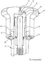
- a locking button is generally shown, which in the exemplary embodiment shown essentially consists of an upper actuation button 6, which can be made of any material, preferably a metal or plastic material.
- the latching mechanism is arranged in the central center bore 14 of the actuating button 6, which in the exemplary embodiment shown essentially consists of a latching sleeve 8, which is received in the interior of the actuating button 6 in a rotationally fixed and immovable manner and which interacts with an associated, approximately cylindrical guide sleeve 3, whereby the guide sleeve 3 can also consist of any material, such as. B. a metal or a plastic material.
- the locking mechanism consisting of the locking sleeve 8 is arranged in the central center bore 14 and that there are no radially protruding parts from the guide sleeve 3 that belong to the locking mechanism and that might be susceptible to contamination.
- the guide sleeve 3 can therefore be attached to any mounting surface with any screw or fixation.
- the guide sleeve 3 has at its lower end a first circumferential sealing ring 5 which is embedded in a radial projection of the guide sleeve 3.
- a sealing nut 1 is provided, which is also provided on its radial outer circumference with a sealing ring 5, which is also embedded there.
- the sealing nut 1 is also screwed onto the guide sleeve 3 with a further sealing ring 4 on an associated external thread.
- a (thereby sealed) clamping receptacle 10 is formed, into which, for example, a fastening plate 11 can engage, as a result of which the entire locking bolt is arranged on a fastening plate (only partially shown) and in one there Hole can be set.
- the guide sleeve 3 has a central center bore 17, in which a bolt 2, which is displaceable in the axial direction, is designed to be spring-loaded due to the force of a compression spring 7.
- the bolt 2 reaches through the bore of the sealing nut 1 in a sealed manner and thus forms an actuating end, as a result of which the bolt 2 can snap into a machine-fixed bore of a machine housing, not shown, or can be disengaged from this machine-fixed bore.
- a radially inwardly directed rod seal 9 is integrated on the lower foot side of the actuation button 6, the inner circumference of which seals against the outer circumference of the guide sleeve 3 so that the entire actuation button 6 in in the axial direction (in the direction of arrow 23 and in the opposite direction) can be moved in a spring-loaded manner on the cylindrical guide sleeve 3 in a sealed manner.
- the guide sleeve 3 engages with a second guide sleeve 12 which is open at the top and which is an integral part of the first guide sleeve 3, in the central central bore of the actuation button and the outer circumference of the second guide sleeve 12 forms a sliding surface 13 to the inner circumference of the actuation button in the area of the central center hole 14.
- the hygienic design is achieved in that the locking mechanism 27, 28 in the central central bore of the actuating button 6 on the inner end face region 35 of the central central bore 17 through the in the axial Distance arranged rod seal 9 is arranged in a sealed manner, and the guide sleeve 3 with the coaxial, second axial guide sleeve 12 extends in a sealed manner into the central central bore 14 of the actuating button 6 through the rod seal 9.
- the bolt 2 is connected to an upper threaded bolt 19 in one piece or separated from the material, which is screwed into an associated bore 18 on the inside of the actuating button 6.
- screw connection instead of such a screw connection, other connections, e.g. an adhesive connection or a welded connection can be used. It is also possible that the threaded bolt 19 is designed as a rivet bolt and riveted to the actuating button 6.
- the locking mechanism essentially consists of a sleeve-shaped locking sleeve 8, which is fixed with its one, eccentrically and in the axial direction locking pin 22 in a blind hole 21 of the actuating button 6 in the region of the inner end wall 35 and is held there immovably. It is therefore non-rotatably and immovably connected to the operating button 6.
- the sleeve-shaped locking sleeve 8 forms an axially downwardly extending sleeve extension 15, which likewise defines a central center bore 17 (see Figure 8 ).
- the center bore 17 with the central radial play shown can also be completely omitted because the sleeve extension 15 of the locking sleeve 8 can also engage in a form-fitting manner on the outer circumference of the bolt 2.
- the latching mechanism itself is formed by an end stop face 16 in the guide sleeve 3, which interacts with an associated latching contour 28 of the latching sleeve 8, as will be shown later in the further drawings according to FIG Figures 6 to 8 will be described.
- the Figure 2 shows compared to Figure 1 that the operating button 6 has now been turned by 90 °.
- angles of rotation can be provided, such as. B. 30 °, 60 °, 120 ° or the like. This depends on the type of locking contour 28, 34, which is based on the drawings Figure 6 to 8 will be described. More than two locking positions can also be provided.
- a central threaded bore 20 is machined into the inside of the actuating button 6, into which the threaded bolt 19 of the bolt 2 is screwed.
- FIG. 6 shows the perspective view of a locking sleeve 8, which consists essentially of a cylindrical ring extension 29 which has a central bore through which the bolt 2 extends.
- a locking pin 22 is formed eccentrically to the central bore 18 and, according to the above exemplary embodiments, engages in an associated blind bore 21 in the interior of the actuating button 6 and is anchored there.
- Such an attachment has the advantage that a particularly reliable and simple attachment of the locking sleeve 8 is ensured in the interior of the actuating button 6.
- a latching contour 28 on the latching sleeve side is formed on the lower end face of the sleeve projection 15, the latching lug 31 belonging to the latching contour 28 extending into the sleeve projection 15.
- the sleeve extension 15 is cylindrical and the radially protruding mutually opposite latching lugs 31 are formed only at the bottom in the region of the latching contour 28.
- the Figure 7 shows the special design of the locking contour 28 of the locking sleeve 8 on the lower end face, where it can be seen that the two diametrically opposite locking lugs 31 form a locking area 33 and intervening arc sections 30 are present, which are not designed to lock.
- the locking lugs 31 are formed in the region of an inclined chamfer 32, as is shown in FIG Figure 8 is recognizable.
- the Figure 8 shows that the locking contour is formed in the region of the chamfer 32, which runs obliquely at an angle to the longitudinal axis.
- the chamfer 32 thus forms, so to speak, a run-up slope on the housing-side latching contour 34, so that it is not necessary to lift the actuating button.
- the chamfer 32 would then be omitted and there would then be a smooth end face which is not inclined at an angle to the vertical.
- bevel 32 which is designed as an oblique straight line
- curved bevels ie the oblique straight line according to FIG Figure 8 , which forms the chamfer 32, can also be profiled in an arc shape.
- the Figure 10 shows the front view of the guide sleeve 3 in the direction of arrow X to Figure 9 ,
- the locking lug 26 forms the locking contour 34, which in Figure 10 is shown.
- the latching contour essentially consists of two diametrically opposite latching lugs, which are also referred to as locking lugs 26, while in the intermediate space there are two opposite stop surfaces 26 which are curved and which are not used for latching.
- the two spaced-apart guide surfaces of the latching are accordingly arranged in the region of the latching recess 27.
- the locking lug 31 of the locking sleeve 8 lies on the locking projection 26 with the locking contour 34 according to Figure 10 the guide sleeve 3.
- the latching mechanism with the spaced-apart guide surfaces 16, 26, 34 which are formed in the area of a central latching recess 27 in the interior of the guide sleeve 3, are integrated in a sealed manner in the interior of the actuating button 6, so that none of the guide sleeve 3 there are more radially protruding parts.
Landscapes
- Engineering & Computer Science (AREA)
- General Engineering & Computer Science (AREA)
- Mechanical Engineering (AREA)
- Physics & Mathematics (AREA)
- General Physics & Mathematics (AREA)
- Automation & Control Theory (AREA)
- Quick-Acting Or Multi-Walled Pipe Joints (AREA)
- Preventing Unauthorised Actuation Of Valves (AREA)
- Lock And Its Accessories (AREA)
- Dowels (AREA)
- Closures For Containers (AREA)
Applications Claiming Priority (1)
| Application Number | Priority Date | Filing Date | Title |
|---|---|---|---|
| DE102018118617.7A DE102018118617A1 (de) | 2018-08-01 | 2018-08-01 | Rastbolzen mit geschützter Rastmechanik |
Publications (2)
| Publication Number | Publication Date |
|---|---|
| EP3605268A1 true EP3605268A1 (fr) | 2020-02-05 |
| EP3605268B1 EP3605268B1 (fr) | 2026-03-25 |
Family
ID=66912524
Family Applications (1)
| Application Number | Title | Priority Date | Filing Date |
|---|---|---|---|
| EP19178332.3A Active EP3605268B1 (fr) | 2018-08-01 | 2019-06-05 | Boulon d'encliquetage à mécanique d'encliquetage protégée |
Country Status (4)
| Country | Link |
|---|---|
| US (1) | US11674541B2 (fr) |
| EP (1) | EP3605268B1 (fr) |
| CN (1) | CN110792669B (fr) |
| DE (1) | DE102018118617A1 (fr) |
Cited By (1)
| Publication number | Priority date | Publication date | Assignee | Title |
|---|---|---|---|---|
| CN114623136A (zh) * | 2020-12-10 | 2022-06-14 | 欧途瑰泰标准件有限责任及合伙两合公司 | 弹簧加载的卡锁销 |
Families Citing this family (3)
| Publication number | Priority date | Publication date | Assignee | Title |
|---|---|---|---|---|
| CN115107081B (zh) * | 2021-11-01 | 2026-04-21 | 杭州申昊科技股份有限公司 | 一种机械臂的末端夹持工具 |
| US11726519B2 (en) | 2021-12-17 | 2023-08-15 | Raytheon Company | Clocking spring for a rotatable shaft |
| US12055175B2 (en) * | 2022-05-18 | 2024-08-06 | Hanwit Precision Industries Ltd. | Floating fastener |
Citations (6)
| Publication number | Priority date | Publication date | Assignee | Title |
|---|---|---|---|---|
| US4113221A (en) * | 1977-05-27 | 1978-09-12 | Cramer Industries, Inc. | Locking device |
| EP1236910A2 (fr) * | 2001-03-02 | 2002-09-04 | Otto Ganter GmbH & Co. KG Normteilefabrik | Bouton poussoir à ressort |
| DE10338621B4 (de) | 2003-08-22 | 2009-02-26 | Otto Ganter Gmbh & Co. Kg Normteilefabrik | Federbelasteter Rastbolzen |
| EP2163772A1 (fr) | 2008-09-13 | 2010-03-17 | Otto Ganter GmbH & Co. KG Normteilefabrik | Boulon d'arrêt doté d'un cran d'arrêt et d'une tête de déverrouillage |
| DE202008013348U1 (de) | 2008-10-07 | 2010-03-25 | Otto Ganter & Co. Kg Normteilefabrik | Rastbolzen mit Verriegelungsmechanik |
| DE202015003789U1 (de) | 2015-05-23 | 2015-07-20 | Otto Ganter Gmbh & Co. Kg Normteilefabrik | Rastbolzen |
Family Cites Families (16)
| Publication number | Priority date | Publication date | Assignee | Title |
|---|---|---|---|---|
| US2635317A (en) * | 1948-10-29 | 1953-04-21 | Aerolex Ltd | Quick-release fastener |
| US4165854A (en) * | 1978-03-29 | 1979-08-28 | Cramer Industries, Inc. | Eccentric pawl for chair locking device |
| US5586852A (en) * | 1993-12-28 | 1996-12-24 | Otto Ganter & Co. Kg | Spring-loaded press pin |
| CN1153011C (zh) * | 1998-04-14 | 2004-06-09 | 索斯科公司 | 改进的系留螺钉及其制造方法 |
| FR2791214B1 (fr) * | 1999-03-17 | 2001-06-01 | Mitsubishi Electric France | Accouplement liberable d'un teton de suspension sur une paroi d'un telephone mobile |
| CA2442707A1 (fr) * | 2001-05-30 | 2002-12-05 | Pem Management, Inc. | Attache de panneaux a rotation rapide |
| US7585126B2 (en) * | 2007-06-04 | 2009-09-08 | Cooler Master Co., Ltd. | Screwless fixing assembly |
| EP2177774B1 (fr) * | 2008-10-13 | 2011-11-30 | Siemens Aktiengesellschaft | Elément de fixation et dispositif destiné à la réception d'un élément de fixation |
| DE202009004833U1 (de) * | 2009-05-19 | 2009-09-24 | Ebner, Johann | Rastelement |
| US8393840B2 (en) * | 2011-02-01 | 2013-03-12 | Hanwit Precision Industries Ltd. | Floating fastener |
| TW201248027A (en) * | 2011-05-24 | 2012-12-01 | Hanwit Prec Ind Ltd | Fixing bolt |
| US20140099155A1 (en) * | 2012-10-04 | 2014-04-10 | Xiamen Xintianda Corporation Development Ltd. Co. | Connection Unit For Slide Of Rod |
| DE102013006720A1 (de) * | 2013-04-19 | 2014-10-23 | Brose Fahrzeugteile Gmbh & Co. Kommanditgesellschaft, Hallstadt | Verbindungselement sowie Verbindungsanordnung |
| US9091293B1 (en) * | 2014-04-18 | 2015-07-28 | Hanwit Precision Industries Ltd. | Rotary fastener |
| CN206245490U (zh) * | 2015-12-04 | 2017-06-13 | 保力集团有限责任公司 | 用于连接结构部件的联接器以及设置有该联接器的桁架 |
| DE202016107318U1 (de) * | 2016-12-23 | 2017-01-24 | Resbig Technology Gmbh | Manuell betätigbare Verriegelungseinrichtung |
-
2018
- 2018-08-01 DE DE102018118617.7A patent/DE102018118617A1/de active Pending
- 2018-12-21 US US16/230,731 patent/US11674541B2/en active Active
- 2018-12-28 CN CN201811616952.0A patent/CN110792669B/zh active Active
-
2019
- 2019-06-05 EP EP19178332.3A patent/EP3605268B1/fr active Active
Patent Citations (9)
| Publication number | Priority date | Publication date | Assignee | Title |
|---|---|---|---|---|
| US4113221A (en) * | 1977-05-27 | 1978-09-12 | Cramer Industries, Inc. | Locking device |
| EP1236910A2 (fr) * | 2001-03-02 | 2002-09-04 | Otto Ganter GmbH & Co. KG Normteilefabrik | Bouton poussoir à ressort |
| DE10338621B4 (de) | 2003-08-22 | 2009-02-26 | Otto Ganter Gmbh & Co. Kg Normteilefabrik | Federbelasteter Rastbolzen |
| EP2163772A1 (fr) | 2008-09-13 | 2010-03-17 | Otto Ganter GmbH & Co. KG Normteilefabrik | Boulon d'arrêt doté d'un cran d'arrêt et d'une tête de déverrouillage |
| DE102008047041A1 (de) | 2008-09-13 | 2010-03-25 | Otto Ganter Gmbh & Co. Kg Normteilefabrik | Rastbolzen mit Rastsperre und Entriegelungsknopf |
| EP2163772B1 (fr) | 2008-09-13 | 2012-12-05 | Otto Ganter GmbH & Co. KG Normteilefabrik | Boulon d'arrêt doté d'un cran d'arrêt et d'une tête de déverrouillage |
| DE202008013348U1 (de) | 2008-10-07 | 2010-03-25 | Otto Ganter & Co. Kg Normteilefabrik | Rastbolzen mit Verriegelungsmechanik |
| DE202015003789U1 (de) | 2015-05-23 | 2015-07-20 | Otto Ganter Gmbh & Co. Kg Normteilefabrik | Rastbolzen |
| EP3098461A1 (fr) * | 2015-05-23 | 2016-11-30 | Otto Ganter GmbH & Co. KG Normteilefabrik | Boulon d'arret |
Non-Patent Citations (1)
| Title |
|---|
| GERHARD HAUSER: "Hygienische Produktionstechnologie", 2008, WILEY-VCH VERLAG GMBH & CO. KGAA, pages: 1 - 7 |
Cited By (4)
| Publication number | Priority date | Publication date | Assignee | Title |
|---|---|---|---|---|
| CN114623136A (zh) * | 2020-12-10 | 2022-06-14 | 欧途瑰泰标准件有限责任及合伙两合公司 | 弹簧加载的卡锁销 |
| EP4012200A1 (fr) * | 2020-12-10 | 2022-06-15 | Otto Ganter GmbH & Co. KG Normteilefabrik | Boulon d'encliquetage sollicité par ressort |
| CN114623136B (zh) * | 2020-12-10 | 2024-04-19 | 欧途瑰泰标准件有限责任及合伙两合公司 | 弹簧加载的卡锁销 |
| US12044262B2 (en) | 2020-12-10 | 2024-07-23 | Otto Ganter Gmbh & Co. Kg Normteilefabrik | Spring-loaded locking bolt |
Also Published As
| Publication number | Publication date |
|---|---|
| US11674541B2 (en) | 2023-06-13 |
| EP3605268B1 (fr) | 2026-03-25 |
| US20200040928A1 (en) | 2020-02-06 |
| DE102018118617A1 (de) | 2020-02-06 |
| CN110792669A (zh) | 2020-02-14 |
| CN110792669B (zh) | 2022-04-15 |
Similar Documents
| Publication | Publication Date | Title |
|---|---|---|
| EP3605268B1 (fr) | Boulon d'encliquetage à mécanique d'encliquetage protégée | |
| DE4100374C2 (de) | Lösbarer Verriegelungsmechanismus | |
| DE202016005647U1 (de) | Sanitäre Auslaufvorrichtung und sanitäre Armatur | |
| DE202007003957U1 (de) | Kabelverschraubung mit Schraubhülse und Überwurfmutter | |
| EP1302757B1 (fr) | Joint à labyrinthes pourvu d'un anneau détachable et balance | |
| DE29503585U1 (de) | Anschlußstück für die Rohrleitungskupplung eines Hochdruckreinigungsgeräts | |
| AT392233B (de) | Arbeitsgeraet, wie gartengeraet, putzgeraet od. dgl. | |
| EP3941850A1 (fr) | Système d'emballage et procédé associé pour manipuler un composant de préparation de produit | |
| EP2679838A1 (fr) | Dispositif de liaison hygiénique | |
| EP1704353A1 (fr) | Robinet sanitaire | |
| EP3608491B1 (fr) | Ferrure de verrouillage étanchéifié | |
| EP4462003A1 (fr) | Raccord pour composants conduisant l'eau | |
| DE10317342B4 (de) | Schnellspannsystem mit Handbetätigung | |
| DE4111475C2 (de) | Rohrpostbüchse | |
| EP3444210B1 (fr) | Dispositif de connexion pour raccorder un premier conteneur flexible à un second conteneur de dimensions stables | |
| DE202014102948U1 (de) | Schonaufsatz für einen Maulschlüssel und Maulschlüssel-Werkzeug | |
| EP0499886B1 (fr) | Robinetterie murale sanitaire | |
| WO1994007072A1 (fr) | Raccord de tuyaux demontable | |
| DE4111494A1 (de) | Rohrpostbuechse | |
| DE102016011092A1 (de) | Sanitäre Auslaufvorrichtung und sanitäre Armatur | |
| DE2929458A1 (de) | An dem kupplungsstueck von wasseranschlussgeraeten anbringbare vorrichtung mit der funktion eines absperrhahnes | |
| DE102020108181A1 (de) | Vorrichtung zur austauschbaren Befestigung von Formatteilen | |
| DE10148708B4 (de) | Verschlußelement mit Schraubgewinde und Ringdichtung | |
| EP2301408A2 (fr) | Lave-vaisselle | |
| DE102010035515A1 (de) | Rolle für verfahrbare Gegenstände |
Legal Events
| Date | Code | Title | Description |
|---|---|---|---|
| PUAI | Public reference made under article 153(3) epc to a published international application that has entered the european phase |
Free format text: ORIGINAL CODE: 0009012 |
|
| STAA | Information on the status of an ep patent application or granted ep patent |
Free format text: STATUS: THE APPLICATION HAS BEEN PUBLISHED |
|
| AK | Designated contracting states |
Kind code of ref document: A1 Designated state(s): AL AT BE BG CH CY CZ DE DK EE ES FI FR GB GR HR HU IE IS IT LI LT LU LV MC MK MT NL NO PL PT RO RS SE SI SK SM TR |
|
| AX | Request for extension of the european patent |
Extension state: BA ME |
|
| STAA | Information on the status of an ep patent application or granted ep patent |
Free format text: STATUS: REQUEST FOR EXAMINATION WAS MADE |
|
| 17P | Request for examination filed |
Effective date: 20200324 |
|
| RBV | Designated contracting states (corrected) |
Designated state(s): AL AT BE BG CH CY CZ DE DK EE ES FI FR GB GR HR HU IE IS IT LI LT LU LV MC MK MT NL NO PL PT RO RS SE SI SK SM TR |
|
| STAA | Information on the status of an ep patent application or granted ep patent |
Free format text: STATUS: EXAMINATION IS IN PROGRESS |
|
| 17Q | First examination report despatched |
Effective date: 20220610 |
|
| GRAP | Despatch of communication of intention to grant a patent |
Free format text: ORIGINAL CODE: EPIDOSNIGR1 |
|
| STAA | Information on the status of an ep patent application or granted ep patent |
Free format text: STATUS: GRANT OF PATENT IS INTENDED |
|
| INTG | Intention to grant announced |
Effective date: 20251120 |
|
| GRAS | Grant fee paid |
Free format text: ORIGINAL CODE: EPIDOSNIGR3 |
|
| GRAA | (expected) grant |
Free format text: ORIGINAL CODE: 0009210 |
|
| STAA | Information on the status of an ep patent application or granted ep patent |
Free format text: STATUS: THE PATENT HAS BEEN GRANTED |
|
| AK | Designated contracting states |
Kind code of ref document: B1 Designated state(s): AL AT BE BG CH CY CZ DE DK EE ES FI FR GB GR HR HU IE IS IT LI LT LU LV MC MK MT NL NO PL PT RO RS SE SI SK SM TR |
|
| REG | Reference to a national code |
Ref country code: CH Ref legal event code: F10 Free format text: ST27 STATUS EVENT CODE: U-0-0-F10-F00 (AS PROVIDED BY THE NATIONAL OFFICE) Effective date: 20260325 Ref country code: GB Ref legal event code: FG4D Free format text: NOT ENGLISH |
|
| REG | Reference to a national code |
Ref country code: DE Ref legal event code: R096 Ref document number: 502019014502 Country of ref document: DE |
|
| REG | Reference to a national code |
Ref country code: IE Ref legal event code: FG4D Free format text: LANGUAGE OF EP DOCUMENT: GERMAN |