EP3605488A1 - Verwaltung mehrerer autonomer fahrzeuge - Google Patents
Verwaltung mehrerer autonomer fahrzeuge Download PDFInfo
- Publication number
- EP3605488A1 EP3605488A1 EP19187197.9A EP19187197A EP3605488A1 EP 3605488 A1 EP3605488 A1 EP 3605488A1 EP 19187197 A EP19187197 A EP 19187197A EP 3605488 A1 EP3605488 A1 EP 3605488A1
- Authority
- EP
- European Patent Office
- Prior art keywords
- user
- autonomous vehicle
- computer system
- location
- autonomous
- Prior art date
- Legal status (The legal status is an assumption and is not a legal conclusion. Google has not performed a legal analysis and makes no representation as to the accuracy of the status listed.)
- Granted
Links
Images





















Classifications
-
- B—PERFORMING OPERATIONS; TRANSPORTING
- B60—VEHICLES IN GENERAL
- B60W—CONJOINT CONTROL OF VEHICLE SUB-UNITS OF DIFFERENT TYPE OR DIFFERENT FUNCTION; CONTROL SYSTEMS SPECIALLY ADAPTED FOR HYBRID VEHICLES; ROAD VEHICLE DRIVE CONTROL SYSTEMS FOR PURPOSES NOT RELATED TO THE CONTROL OF A PARTICULAR SUB-UNIT
- B60W60/00—Drive control systems specially adapted for autonomous road vehicles
- B60W60/001—Planning or execution of driving tasks
- B60W60/0025—Planning or execution of driving tasks specially adapted for specific operations
- B60W60/00253—Taxi operations
-
- G—PHYSICS
- G08—SIGNALLING
- G08G—TRAFFIC CONTROL SYSTEMS
- G08G1/00—Traffic control systems for road vehicles
- G08G1/20—Monitoring the location of vehicles belonging to a group, e.g. fleet of vehicles, countable or determined number of vehicles
- G08G1/202—Dispatching vehicles on the basis of a location, e.g. taxi dispatching
-
- G—PHYSICS
- G01—MEASURING; TESTING
- G01C—MEASURING DISTANCES, LEVELS OR BEARINGS; SURVEYING; NAVIGATION; GYROSCOPIC INSTRUMENTS; PHOTOGRAMMETRY OR VIDEOGRAMMETRY
- G01C21/00—Navigation; Navigational instruments not provided for in groups G01C1/00 - G01C19/00
- G01C21/26—Navigation; Navigational instruments not provided for in groups G01C1/00 - G01C19/00 specially adapted for navigation in a road network
- G01C21/34—Route searching; Route guidance
- G01C21/3407—Route searching; Route guidance specially adapted for specific applications
- G01C21/3415—Dynamic re-routing, e.g. recalculating the route when the user deviates from calculated route or after detecting real-time traffic data or accidents
-
- G—PHYSICS
- G01—MEASURING; TESTING
- G01C—MEASURING DISTANCES, LEVELS OR BEARINGS; SURVEYING; NAVIGATION; GYROSCOPIC INSTRUMENTS; PHOTOGRAMMETRY OR VIDEOGRAMMETRY
- G01C21/00—Navigation; Navigational instruments not provided for in groups G01C1/00 - G01C19/00
- G01C21/26—Navigation; Navigational instruments not provided for in groups G01C1/00 - G01C19/00 specially adapted for navigation in a road network
- G01C21/34—Route searching; Route guidance
- G01C21/3407—Route searching; Route guidance specially adapted for specific applications
- G01C21/3438—Rendezvous; Ride sharing
-
- G—PHYSICS
- G06—COMPUTING OR CALCULATING; COUNTING
- G06Q—INFORMATION AND COMMUNICATION TECHNOLOGY [ICT] SPECIALLY ADAPTED FOR ADMINISTRATIVE, COMMERCIAL, FINANCIAL, MANAGERIAL OR SUPERVISORY PURPOSES; SYSTEMS OR METHODS SPECIALLY ADAPTED FOR ADMINISTRATIVE, COMMERCIAL, FINANCIAL, MANAGERIAL OR SUPERVISORY PURPOSES, NOT OTHERWISE PROVIDED FOR
- G06Q10/00—Administration; Management
- G06Q10/02—Reservations, e.g. for tickets, services or events
-
- G—PHYSICS
- G06—COMPUTING OR CALCULATING; COUNTING
- G06Q—INFORMATION AND COMMUNICATION TECHNOLOGY [ICT] SPECIALLY ADAPTED FOR ADMINISTRATIVE, COMMERCIAL, FINANCIAL, MANAGERIAL OR SUPERVISORY PURPOSES; SYSTEMS OR METHODS SPECIALLY ADAPTED FOR ADMINISTRATIVE, COMMERCIAL, FINANCIAL, MANAGERIAL OR SUPERVISORY PURPOSES, NOT OTHERWISE PROVIDED FOR
- G06Q10/00—Administration; Management
- G06Q10/04—Forecasting or optimisation specially adapted for administrative or management purposes, e.g. linear programming or "cutting stock problem"
- G06Q10/047—Optimisation of routes or paths, e.g. travelling salesman problem
-
- G—PHYSICS
- G06—COMPUTING OR CALCULATING; COUNTING
- G06Q—INFORMATION AND COMMUNICATION TECHNOLOGY [ICT] SPECIALLY ADAPTED FOR ADMINISTRATIVE, COMMERCIAL, FINANCIAL, MANAGERIAL OR SUPERVISORY PURPOSES; SYSTEMS OR METHODS SPECIALLY ADAPTED FOR ADMINISTRATIVE, COMMERCIAL, FINANCIAL, MANAGERIAL OR SUPERVISORY PURPOSES, NOT OTHERWISE PROVIDED FOR
- G06Q50/00—Information and communication technology [ICT] specially adapted for implementation of business processes of specific business sectors, e.g. utilities or tourism
- G06Q50/40—Business processes related to the transportation industry
-
- G—PHYSICS
- G08—SIGNALLING
- G08G—TRAFFIC CONTROL SYSTEMS
- G08G1/00—Traffic control systems for road vehicles
- G08G1/005—Traffic control systems for road vehicles including pedestrian guidance indicator
-
- G—PHYSICS
- G08—SIGNALLING
- G08G—TRAFFIC CONTROL SYSTEMS
- G08G1/00—Traffic control systems for road vehicles
- G08G1/01—Detecting movement of traffic to be counted or controlled
- G08G1/0104—Measuring and analyzing of parameters relative to traffic conditions
- G08G1/0137—Measuring and analyzing of parameters relative to traffic conditions for specific applications
- G08G1/0145—Measuring and analyzing of parameters relative to traffic conditions for specific applications for active traffic flow control
-
- G—PHYSICS
- G08—SIGNALLING
- G08G—TRAFFIC CONTROL SYSTEMS
- G08G1/00—Traffic control systems for road vehicles
- G08G1/09—Arrangements for giving variable traffic instructions
- G08G1/0962—Arrangements for giving variable traffic instructions having an indicator mounted inside the vehicle, e.g. giving voice messages
- G08G1/0968—Systems involving transmission of navigation instructions to the vehicle
- G08G1/096805—Systems involving transmission of navigation instructions to the vehicle where the transmitted instructions are used to compute a route
- G08G1/096811—Systems involving transmission of navigation instructions to the vehicle where the transmitted instructions are used to compute a route where the route is computed offboard
-
- G—PHYSICS
- G08—SIGNALLING
- G08G—TRAFFIC CONTROL SYSTEMS
- G08G1/00—Traffic control systems for road vehicles
- G08G1/09—Arrangements for giving variable traffic instructions
- G08G1/0962—Arrangements for giving variable traffic instructions having an indicator mounted inside the vehicle, e.g. giving voice messages
- G08G1/0968—Systems involving transmission of navigation instructions to the vehicle
- G08G1/096833—Systems involving transmission of navigation instructions to the vehicle where different aspects are considered when computing the route
- G08G1/096838—Systems involving transmission of navigation instructions to the vehicle where different aspects are considered when computing the route where the user preferences are taken into account or the user selects one route out of a plurality
-
- G—PHYSICS
- G08—SIGNALLING
- G08G—TRAFFIC CONTROL SYSTEMS
- G08G1/00—Traffic control systems for road vehicles
- G08G1/09—Arrangements for giving variable traffic instructions
- G08G1/0962—Arrangements for giving variable traffic instructions having an indicator mounted inside the vehicle, e.g. giving voice messages
- G08G1/0968—Systems involving transmission of navigation instructions to the vehicle
- G08G1/096833—Systems involving transmission of navigation instructions to the vehicle where different aspects are considered when computing the route
- G08G1/096844—Systems involving transmission of navigation instructions to the vehicle where different aspects are considered when computing the route where the complete route is dynamically recomputed based on new data
-
- H—ELECTRICITY
- H04—ELECTRIC COMMUNICATION TECHNIQUE
- H04W—WIRELESS COMMUNICATION NETWORKS
- H04W4/00—Services specially adapted for wireless communication networks; Facilities therefor
- H04W4/02—Services making use of location information
-
- H—ELECTRICITY
- H04—ELECTRIC COMMUNICATION TECHNIQUE
- H04W—WIRELESS COMMUNICATION NETWORKS
- H04W4/00—Services specially adapted for wireless communication networks; Facilities therefor
- H04W4/30—Services specially adapted for particular environments, situations or purposes
- H04W4/40—Services specially adapted for particular environments, situations or purposes for vehicles, e.g. vehicle-to-pedestrians [V2P]
-
- G—PHYSICS
- G08—SIGNALLING
- G08G—TRAFFIC CONTROL SYSTEMS
- G08G1/00—Traffic control systems for road vehicles
- G08G1/01—Detecting movement of traffic to be counted or controlled
- G08G1/0104—Measuring and analyzing of parameters relative to traffic conditions
- G08G1/0125—Traffic data processing
- G08G1/0129—Traffic data processing for creating historical data or processing based on historical data
Definitions
- This description relates to a computer system for controlling the operation of multiple autonomous vehicles.
- Autonomous vehicles can be used to transport people and/or cargo (e.g., packages, objects, or other items) from one location to another.
- an autonomous vehicle can navigate to the location of a person, wait for the person to board the autonomous vehicle, and navigate to a specified destination (e.g., a location selected by the person).
- a specified destination e.g., a location selected by the person.
- an autonomous vehicle can navigate to the location of cargo, wait for the cargo to be loaded into the autonomous vehicle, and navigate to a specified destination (e.g., a delivery location for the cargo).
- a computer system can control the operation of a fleet of autonomous vehicles.
- a computer system can deploy autonomous vehicles to one or more locations or regions, assign transportation tasks to each of the autonomous vehicles (e.g., pick up and transport passengers, pick up and transport cargo, etc.), assign maintenance tasks to each of the autonomous vehicles (e.g., charge their batteries at charging stations, receive repairs at a service station, etc.), and/or assign other tasks to each of the autonomous vehicles.
- the computer system can include one or more devices on a communications network (e.g., a centralized network, peer-to-peer network, decentralized network, etc.).
- the computer system is a centralized computer system.
- a computer system receives vehicle telemetry data.
- the vehicle telemetry data indicates a respective geographical location of each autonomous vehicle of a plurality of autonomous vehicles.
- the computer system also receives user profile data.
- the user profile data indicates a respective geographical location of each user of a plurality of users.
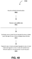
- the computer system estimates, based on the user profile data, one or more future requests by one or more of the users for use of one or more of the autonomous vehicles. Each estimated future request is associated with a respective geographical location and a respective time.
- the computer system transmits one or more command signals to one or more of the autonomous vehicles based on the one or more estimated future requests.
- Each command signal includes instructions for a respective autonomous vehicle to navigate to a respective geographical location at a respective time.
- Implementations of this aspect can include one or more of the following features.
- the vehicle telemetry data includes an indication of a speed of an autonomous vehicle of the plurality of autonomous vehicles.
- the vehicle telemetry data includes an indication of a location of an autonomous vehicle of the plurality of autonomous vehicles.
- the vehicle telemetry data includes an indication of a heading of an autonomous vehicle of the plurality of autonomous vehicles
- the vehicle telemetry data includes an indication of a route of an autonomous vehicle of the plurality of autonomous vehicles.
- the user profile data includes an indication of a location of a user of the plurality of users.
- the user profile data includes an indication of a travel history of a user of the plurality of users.
- the user profile data includes one or more demographic indicators of a user of the plurality of users.
- the user profile data includes an indication of a preference of a user of the plurality of users.
- the user profile data includes an indication of a trend associated with a user of the plurality of users.
- the one or more command signals include instructions to an autonomous vehicle of the plurality of autonomous vehicles to navigate to a location associated with a user of the plurality of users.
- the one or more command signals include instructions to an autonomous vehicle of the plurality of autonomous vehicles to navigate to an idling location.
- the one or more command signals include instructions to an autonomous vehicle of the plurality of autonomous vehicles to navigate to a geographical region different from a current geographical region of the autonomous vehicle.
- the one or more command signals include instructions to an autonomous vehicle of the plurality of autonomous vehicles to navigate to a location associated with a package.
- the one or more command signals include instructions to an autonomous vehicle of the plurality of autonomous vehicles to navigate to a location associated with an electrical charging station.
- the one or more future requests are estimated based on a predictive model of a future demand for use of one or more of the autonomous vehicles.
- the one or more future requests are estimated based on event information indicating an occurrence or predicted occurrence of one or more events.
- the one or more future requests are estimated based on a current demand for use of one or more of the autonomous vehicles.
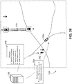
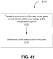
- the one or more command signals include instructions for a first autonomous vehicle to convey a first user along a first portion of a route to a destination requested by the first user. Further, the computer system transmits instructions to the first user to navigate a second portion of the route using a public transportation system. In some embodiments a travel itinerary is generated for the first user. Travel itinerary includes instructions to the first user to navigate the first portion of the route using the first autonomous vehicle, and instructions to the first user to navigate the second portion of the route using the public transportation system.
- the one or more command signals include instructions to a first autonomous vehicle to idle at a first location. Further, the computer system receives a request by a first user for use of the first autonomous vehicle at the first location, and responsive to receiving the request by the first user, assigns the first autonomous vehicle to the first user.
- the computer system receives a request by a first user for use of an autonomous vehicle, The computer system estimates a first length of time associated with assigning a first autonomous vehicle of the plurality of autonomous vehicles for exclusive use of the first user and fulfilling the request using the first autonomous vehicle, and estimates a second length of time associated with assigning a second autonomous vehicle of the plurality of autonomous vehicles for shared use between the first user and one or more additional users and fulfilling the request using the second autonomous vehicle.
- the computer system transmits an indication of the first length of time and the second length of time to the user.
- the computer system receives an input from the first user selecting one of the first autonomous vehicle or the second autonomous vehicle. Responsive to receiving the input from the first user, the computer system assigns the selected first autonomous vehicle or second autonomous vehicle to fulfill the request.
- the computer system determines that a first autonomous vehicle is conveying a first user to a first destination requested by the first user, and determines that navigating to a second destination different from the first destination increases an efficiency of an operation of the first autonomous vehicle.
- the computer system transmits an indication of the second destination for display to the first user, and receives an input by the first user accepting the second destination, Responsive to receiving the input by the first user, the computer system transmits, to the first autonomous vehicle, one or more command signals instructing the first autonomous vehicle to navigate to the second destination instead of the first destination.
- the computer system receives a request from a first user for a first autonomous vehicle.
- the request includes an indication of a first location of the first user.
- the computer system determines that picking up the user at a second location different from the first location increases an efficiency of an operation of the first autonomous vehicle.
- the computer system transmits, to the first user, an indication of the second location.
- the computer system receives, from the first user, an input by the first user accepting the second location.
- the computer system transmits, to the first autonomous vehicle, one or more command signals instructing the first autonomous vehicle to navigate to the second location instead of the first location, and transmits, to the first user, an instruction to navigate to the second location for pickup by the first autonomous vehicle.
- the computer system receives a first request from a first user for use of one of the autonomous vehicles.
- the first request is associated with a first priority metric.
- the computer system receives a second request from a second user for use of one of the autonomous vehicles.
- the second request is associated with a second priority metric.
- the computer system determines that the first priority metric is greater than the second priority metric, and responsive to determining that the first priority metric is greater than the second priority metric, assigns an autonomous vehicle to the first user prior to assigning an autonomous vehicle to the second user.
- connecting elements such as solid or dashed lines or arrows
- the absence of any such connecting elements is not meant to imply that no connection, relationship, or association can exist.
- some connections, relationships, or associations between elements are not shown in the drawings so as not to obscure the disclosure.
- a single connecting element is used to represent multiple connections, relationships or associations between elements.
- a connecting element represents a communication of signals, data, or instructions
- such element represents one or multiple signal paths (e.g., a bus), as may be needed, to affect the communication.
- a computer system can control the operation of a fleet of autonomous vehicles.
- a computer system can deploy autonomous vehicles to one or more locations or regions, assign transportation tasks to each of the autonomous vehicles (e.g., pick up and transport passengers, pick up and transport cargo, etc.), and assign maintenance tasks to each of the autonomous vehicles (e.g., charge their batteries at charging stations, receive repairs at a service station, etc.), and/or assign other tasks to each of the autonomous vehicles.
- the computer system can include one or more devices on a communications network (e.g., a centralized network, peer-to-peer network, decentralized network, etc.).
- the computer system is a centralized computer system.
- a computer system dynamically positions each of the autonomous vehicles based on past, present, or future demand for the autonomous vehicles. For example, the computer system can determine that autonomous vehicles are currently in high demand at a particular location, and direct autonomous vehicles to that location from locations having a lower demand. As another example, the computer system can estimate a future demand for autonomous vehicles (e.g., based on historical and/or current information gathered from the autonomous vehicles, potential passengers, and/or environmental information), and direct autonomous vehicles to certain locations to better meet the estimated demand.
- a future demand for autonomous vehicles e.g., based on historical and/or current information gathered from the autonomous vehicles, potential passengers, and/or environmental information
- some implementation can improve the efficiency and effectiveness of a fleet of autonomous vehicles as a whole, as well as autonomous vehicles individually.
- vehicles can fulfill requests more quickly, thereby increasing the effective capacity of the fleet.
- vehicles spend less time idling without a passenger or cargo, and thus operate more efficiently.
- vehicles can be deployed in an automated manner (e.g., using computer-specific rules), rather than based on the subjective predictions of a human.
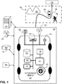
- FIG. 1 shows an example of an autonomous vehicle 100 having autonomous capability.
- autonomous capability refers to a function, feature, or facility that enables a vehicle to be operated without real-time human intervention unless specifically requested by the vehicle.
- an autonomous vehicle is a vehicle that possesses autonomous capability.
- vehicle includes means of transposition of goods or people.
- vehicles for example, cars, buses, trains, airplanes, drones, trucks, boats, ships, submersibles, dirigibles, etc.
- a driverless car is an example of an AV.
- trajectory refers to a path or route generated by an AV to navigate from a first spatiotemporal location to second spatiotemporal location.
- first spatiotemporal location is referred to as the initial or starting location and the second spatiotemporal location is referred to as the destination, final location, goal, goal position, or goal location.
- a trajectory is made up of one or more segments (e.g., sections of road) and each segment is made up of one or more blocks (e.g., portions of a lane or intersection).
- the spatiotemporal locations correspond to real world locations.
- the spatiotemporal locations are pick up or drop-off locations to pick up or drop-off persons or goods.
- sensor includes one or more physical components that detect information about the environment surrounding the physical components.
- Some of the physical components can include electronic components such as analog-to-digital converters, a buffer (such as a RAM and/or a nonvolatile storage) as well as data processing components such as an ASIC (application-specific integrated circuit), a microprocessor and/or a microcontroller.
- ASIC application-specific integrated circuit
- One or more includes a function being performed by one element, a function being performed by more than one element, e.g., in a distributed fashion, several functions being performed by one element, several functions being performed by several elements, or any combination of the above.
- first, second, etc. are, in some instances, used herein to describe various elements, these elements should not be limited by these terms. These terms are only used to distinguish one element from another.
- a first contact could be termed a second contact, and, similarly, a second contact could be termed a first contact, without departing from the scope of the various described embodiments.
- the first contact and the second contact are both contacts, but they are not the same contact.
- the term “if' is, optionally, construed to mean “when” or “upon” or “in response to determining” or “in response to detecting,” depending on the context.
- the phrase “if it is determined” or “if [a stated condition or event] is detected” is, optionally, construed to mean “upon determining” or “in response to determining” or “upon detecting [the stated condition or event]” or “in response to detecting [the stated condition or event],” depending on the context.
- an AV system refers to the AV along with the array of hardware, software, stored data, and data generated in real-time that supports the operation of the AV.
- the AV system is incorporated within the AV.
- the AV system is spread across several locations.
- some of the software of the AV system is implemented on a cloud computing environment similar to cloud computing environment 300 described below with respect to FIG. 3 .
- this document describes technologies applicable to any vehicles that have one or more autonomous capabilities including fully autonomous vehicles, highly autonomous vehicles, and conditionally autonomous vehicles, such as so-called Level 5, Level 4 and Level 3 vehicles, respectively (see SAE International's standard J3016: Taxonomy and Definitions for Terms Related to On-Road Motor Vehicle Automated Driving Systems , which is incorporated by reference in its entirety, for more details on the classification of levels of autonomy in vehicles).
- the technologies descried in this document also are also applicable to partially autonomous vehicles and driver assisted vehicles, such as so-called Level 2 and Level 1 vehicles (see SAE International's standard J3016: Taxonomy and Definitions for Terms Related to On-Road Motor Vehicle Automated Driving Systems).
- one or more of the Level 1, 2, 3, 4 and 5 vehicle systems may automate certain vehicle operations (e.g., steering, braking, and using maps) under certain operating conditions based on processing of sensor inputs.
- vehicle operations e.g., steering, braking, and using maps
- the technologies described in this document can benefit vehicles in any levels, ranging from fully autonomous vehicles to human-operated vehicles.
- an AV system 120 operates the AV 100 autonomously or semi-autonomously along a trajectory 198 through an environment 190 to a destination 199 (sometimes referred to as a final location) while avoiding objects (e.g., natural obstructions 191, vehicles 193, pedestrians 192, cyclists, and other obstacles) and obeying rules of the road (e.g., rules of operation or driving preferences).
- objects e.g., natural obstructions 191, vehicles 193, pedestrians 192, cyclists, and other obstacles
- rules of the road e.g., rules of operation or driving preferences
- the AV system 120 includes devices 101 that are instrumented to receive and act on operational commands from the computer processors 146.
- computing processors 146 are similar to the processor 304 described below in reference to FIG. 3 .
- Examples of devices 101 include a steering control 102, brakes 103, gears, accelerator pedal or other acceleration control mechanisms, windshield wipers, side-door locks, window controls, and turn-indicators.
- the AV system 120 includes sensors 121 for measuring or inferring properties of state or condition of the AV 100, such as the AV's position, linear and angular velocity and acceleration, and heading (e.g., an orientation of the leading end of AV 100).
- sensors 121 are GPS, inertial measurement units (IMU) that measure both vehicle linear accelerations and angular rates, wheel speed sensors for measuring or estimating wheel slip ratios, wheel brake pressure or braking torque sensors, engine torque or wheel torque sensors, and steering angle and angular rate sensors.
- IMU inertial measurement units
- the sensors 121 also include sensors for sensing or measuring properties of the AV's environment.
- sensors for sensing or measuring properties of the AV's environment For example, monocular or stereo video cameras 122 in the visible light, infrared or thermal (or both) spectra, LiDAR 123, radar, ultrasonic sensors, time-of-flight (TOF) depth sensors, speed sensors, temperature sensors, humidity sensors, and precipitation sensors.
- monocular or stereo video cameras 122 in the visible light, infrared or thermal (or both) spectra LiDAR 123, radar, ultrasonic sensors, time-of-flight (TOF) depth sensors, speed sensors, temperature sensors, humidity sensors, and precipitation sensors.
- TOF time-of-flight
- the AV system 120 includes a data storage unit 142 and memory 144 for storing machine instructions associated with computer processors 146 or data collected by sensors 121.
- the data storage unit 142 is similar to the ROM 308 or storage device 310 described below in relation to FIG. 3 .
- memory 144 is similar to the main memory 306 described below.
- the data storage unit 142 and memory 144 store historical, real-time, and/or predictive information about the environment 190.
- the stored information includes maps, driving performance, traffic congestion updates or weather conditions.
- data relating to the environment 190 is transmitted to the AV 100 via a communications channel from a remotely located database 134.
- the AV system 120 includes communications devices 140 for communicating measured or inferred properties of other vehicles' states and conditions, such as positions, linear and angular velocities, linear and angular accelerations, and linear and angular headings to the AV 100.
- These devices include Vehicle-to-Vehicle (V2V) and Vehicle-to-Infrastructure (V2I) communication devices and devices for wireless communications over point-to-point or ad hoc networks or both.
- the communications devices 140 communicate across the electromagnetic spectrum (including radio and optical communications) or other media (e.g., air and acoustic media).
- V2V Vehicle-to-Vehicle
- V2I Vehicle-to-Infrastructure
- V2X Vehicle-to-Everything
- V2X communication typically conforms to one or more communications standards for communication with, between, and among autonomous vehicles.
- the communication devices 140 include communication interfaces. For example, wired, wireless, WiMAX, Wi-Fi, Bluetooth, satellite, cellular, optical, near field, infrared, or radio interfaces.
- the communication interfaces transmit data from a remotely located database 134 to AV system 120.
- the remotely located database 134 is embedded in a cloud computing environment 200 as described in FIG. 2 .
- the communication interfaces 140 transmit data collected from sensors 121 or other data related to the operation of AV 100 to the remotely located database 134.
- communication interfaces 140 transmit information that relates to teleoperations to the AV 100.
- the AV 100 communicates with other remote (e.g., "cloud") servers 136.
- the remotely located database 134 also stores and transmits digital data (e.g., storing data such as road and street locations). Such data is stored on the memory 144 on the AV 100, or transmitted to the AV 100 via a communications channel from the remotely located database 134.
- digital data e.g., storing data such as road and street locations.
- the remotely located database 134 stores and transmits historical information about driving properties (e.g., speed and acceleration profiles) of vehicles that have previously traveled along trajectory 198 at similar times of day.
- driving properties e.g., speed and acceleration profiles
- data may be stored on the memory 144 on the AV 100, or transmitted to the AV 100 via a communications channel from the remotely located database 134.
- Computing devices 146 located on the AV 100 algorithmically generate control actions based on both real-time sensor data and prior information, allowing the AV system 120 to execute its autonomous driving capabilities.
- the AV system 120 includes computer peripherals 132 coupled to computing devices 146 for providing information and alerts to, and receiving input from, a user (e.g., an occupant or a remote user) of the AV 100.
- peripherals 132 are similar to the display 312, input device 314, and cursor controller 316 discussed below in reference to FIG. 3 .
- the coupling is wireless or wired. Any two or more of the interface devices may be integrated into a single device.
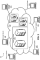
- FIG. 2 illustrates an exemplary "cloud" computing environment.
- Cloud computing is a model of service delivery for enabling convenient, on-demand network access to a shared pool of configurable computing resources (e.g. networks, network bandwidth, servers, processing, memory, storage, applications, virtual machines, and services).
- one or more large cloud data centers house the machines used to deliver the services provided by the cloud.
- the cloud computing environment 200 includes cloud data centers 204a, 204b, and 204c that are interconnected through the cloud 202.
- Data centers 204a, 204b, and 204c provide cloud computing services to computer systems 206a, 206b, 206c, 206d, 206e, and 206f connected to cloud 202.
- the cloud computing environment 200 includes one or more cloud data centers.
- a cloud data center for example the cloud data center 204a shown in FIG. 2 , refers to the physical arrangement of servers that make up a cloud, for example the cloud 202 shown in FIG. 2 , or a particular portion of a cloud.
- servers are physically arranged in the cloud datacenter into rooms, groups, rows, and racks.
- a cloud datacenter has one or more zones, which include one or more rooms of servers. Each room has one or more rows of servers, and each row includes one or more racks. Each rack includes one or more individual server nodes.
- servers in zones, rooms, racks, and/or rows are arranged into groups based on physical infrastructure requirements of the datacenter facility, which include power, energy, thermal, heat, and/or other requirements.
- the server nodes are similar to the computer system described in FIG. 3 .
- the data center 204a has many computing systems distributed through many racks.
- the cloud 202 includes cloud data centers 204a, 204b, and 204c along with the network and networking resources (for example, networking equipment, nodes, routers, switches, and networking cables) that interconnect the cloud data centers 204a, 204b, and 204c and help facilitate the computing systems' 206a-f access to cloud computing services.
- the network represents any combination of one or more local networks, wide area networks, or internetworks coupled using wired or wireless links deployed using terrestrial or satellite connections. Data exchanged over the network, is transferred using any number of network layer protocols, such as Internet Protocol (IP), Multiprotocol Label Switching (MPLS), Asynchronous Transfer Mode (ATM), Frame Relay, etc.
- IP Internet Protocol
- MPLS Multiprotocol Label Switching
- ATM Asynchronous Transfer Mode
- Frame Relay etc.
- the network represents a combination of multiple sub-networks
- different network layer protocols are used at each of the underlying sub-networks.
- the network represents one or more interconnected internetworks, such as the public Internet.
- the computing systems 206a-f or cloud computing services consumers are connected to the cloud 202 through network links and network adapters.
- the computing systems 206a-f are implemented as various computing devices, for example servers, desktops, laptops, tablet, smartphones, IoT devices, autonomous vehicles (including, cars, drones, shuttles, trains, buses, etc.) and consumer electronics.
- the computing systems 206a-f are implemented in or as a part of other systems.
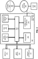
- FIG. 3 illustrates a computer system 300.
- the computer system 300 is a special purpose computing device.
- the special-purpose computing device is hard-wired to perform the techniques or includes digital electronic devices such as one or more application-specific integrated circuits (ASICs) or field programmable gate arrays (FPGAs) that are persistently programmed to perform the techniques, or may include one or more general purpose hardware processors programmed to perform the techniques pursuant to program instructions in firmware, memory, other storage, or a combination.
- ASICs application-specific integrated circuits
- FPGAs field programmable gate arrays
- Such special-purpose computing devices may also combine custom hard-wired logic, ASICs, or FPGAs with custom programming to accomplish the techniques.
- the special-purpose computing devices are desktop computer systems, portable computer systems, handheld devices, network devices or any other device that incorporates hard-wired and/or program logic to implement the techniques.
- the computer system 300 includes a bus 302 or other communication mechanism for communicating information, and a hardware processor 304 coupled with a bus 302 for processing information.
- the hardware processor 304 is, for example, a general-purpose microprocessor.
- the computer system 300 also includes a main memory 306, such as a random-access memory (RAM) or other dynamic storage device, coupled to the bus 302 for storing information and instructions to be executed by processor 304.
- the main memory 306 is used for storing temporary variables or other intermediate information during execution of instructions to be executed by the processor 304.
- Such instructions when stored in non-transitory storage media accessible to the processor 304, render the computer system 300 into a special-purpose machine that is customized to perform the operations specified in the instructions.
- the computer system 300 further includes a read only memory (ROM) 308 or other static storage device coupled to the bus 302 for storing static information and instructions for the processor 304.
- ROM read only memory
- a storage device 310 such as a magnetic disk, optical disk, solid-state drive, or three-dimensional cross point memory is provided and coupled to the bus 302 for storing information and instructions.
- the computer system 300 is coupled via the bus 302 to a display 312, such as a cathode ray tube (CRT), a liquid crystal display (LCD), plasma display, light emitting diode (LED) display, or an organic light emitting diode (OLED) display for displaying information to a computer user.
- a display 312 such as a cathode ray tube (CRT), a liquid crystal display (LCD), plasma display, light emitting diode (LED) display, or an organic light emitting diode (OLED) display for displaying information to a computer user.
- An input device 314, including alphanumeric and other keys, is coupled to bus 302 for communicating information and command selections to the processor 304.
- a cursor controller 316 such as a mouse, a trackball, a touch-enabled display, or cursor direction keys for communicating direction information and command selections to the processor 304 and for controlling cursor movement on the display 312.
- This input device typically has two degrees of freedom in two axes, a first axis (e.g., x-axis) and a second axis (e.g., y-axis), that allows the device to specify positions in a plane.
- a first axis e.g., x-axis
- a second axis e.g., y-axis
- the techniques herein are performed by the computer system 300 in response to the processor 304 executing one or more sequences of one or more instructions contained in the main memory 306. Such instructions are read into the main memory 306 from another storage medium, such as the storage device 310. Execution of the sequences of instructions contained in the main memory 306 causes the processor 304 to perform the process steps described herein. In alternative embodiments, hard-wired circuitry is used in place of or in combination with software instructions.
- Non-volatile media includes, for example, optical disks, magnetic disks, solid-state drives, or three-dimensional cross point memory, such as the storage device 310.
- Volatile media includes dynamic memory, such as the main memory 306.
- Common forms of storage media include, for example, a floppy disk, a flexible disk, hard disk, solid-state drive, magnetic tape, or any other magnetic data storage medium, a CD-ROM, any other optical data storage medium, any physical medium with patterns of holes, a RAM, a PROM, and EPROM, a FLASH-EPROM, NV-RAM, or any other memory chip or cartridge.
- Storage media is distinct from but may be used in conjunction with transmission media.
- Transmission media participates in transferring information between storage media.
- transmission media includes coaxial cables, copper wire and fiber optics, including the wires that comprise the bus 302.
- transmission media can also take the form of acoustic or light waves, such as those generated during radio-wave and infrared data communications.
- various forms of media are involved in carrying one or more sequences of one or more instructions to the processor 304 for execution.
- the instructions are initially carried on a magnetic disk or solid-state drive of a remote computer.
- the remote computer loads the instructions into its dynamic memory and send the instructions over a telephone line using a modem.
- a modem local to the computer system 300 receives the data on the telephone line and use an infrared transmitter to convert the data to an infrared signal.
- An infrared detector receives the data carried in the infrared signal and appropriate circuitry places the data on the bus 302.
- the bus 302 carries the data to the main memory 306, from which processor 304 retrieves and executes the instructions.
- the instructions received by the main memory 306 may optionally be stored on the storage device 310 either before or after execution by processor 304.
- the computer system 300 also includes a communication interface 318 coupled to the bus 302.
- the communication interface 318 provides a two-way data communication coupling to a network link 320 that is connected to a local network 322.
- the communication interface 318 is an integrated service digital network (ISDN) card, cable modem, satellite modem, or a modem to provide a data communication connection to a corresponding type of telephone line.
- ISDN integrated service digital network
- the communication interface 318 is a local area network (LAN) card to provide a data communication connection to a compatible LAN.
- LAN local area network
- wireless links are also implemented.
- the communication interface 318 sends and receives electrical, electromagnetic, or optical signals that carry digital data streams representing various types of information.
- the network link 320 typically provides data communication through one or more networks to other data devices.
- the network link 320 provides a connection through the local network 322 to a host computer 324 or to a cloud data center or equipment operated by an Internet Service Provider (ISP) 326.
- the ISP 326 in turn provides data communication services through the world-wide packet data communication network now commonly referred to as the "Internet" 328.
- the local network 322 and Internet 328 both use electrical, electromagnetic or optical signals that carry digital data streams.
- the signals through the various networks and the signals on the network link 320 and through the communication interface 318, which carry the digital data to and from the computer system 300, are example forms of transmission media.
- the network 320 contains the cloud 202 or a part of the cloud 202 described above.
- the computer system 300 sends messages and receives data, including program code, through the network(s), the network link 320, and the communication interface 318.
- the computer system 300 receives code for processing.
- the received code is executed by the processor 304 as it is received, and/or stored in storage device 310, or other non-volatile storage for later execution.
- FIG. 4 shows an example architecture 400 for an autonomous vehicle (e.g., the AV 100 shown in FIG. 1 ).
- the architecture 400 includes a perception module 402 (sometimes referred to as a perception circuit), a planning module 404 (sometimes referred to as a planning circuit), a control module 406 (sometimes referred to as a control circuit), a localization module 408 (sometimes referred to as a localization circuit), and a database module 410 (sometimes referred to as a database circuit).
- Each module plays a role in the operation of the AV 100.
- the modules 402, 404, 406, 408, and 410 may be part of the AV system 120 shown in FIG. 1 .
- any of the modules 402, 404, 406, 408, and 410 is a combination of computer software and computer hardware.
- the planning module 404 receives data representing a destination 412 and determines data representing a trajectory 414 (sometimes referred to as a route) that can be traveled by the AV 100 to reach (e.g., arrive at) the destination 412. In order for the planning module 404 to determine the data representing the trajectory 414, the planning module 404 receives data from the perception module 402, the localization module 408, and the database module 410.
- a trajectory 414 sometimes referred to as a route
- the planning module 404 receives data from the perception module 402, the localization module 408, and the database module 410.
- the perception module 402 identifies nearby physical objects using one or more sensors 121, e.g., as also shown in FIG. 1 .
- the objects are classified (e.g., grouped into types such as pedestrian, bicycle, automobile, traffic sign, etc.) and data representing the classified objects 416 is provided to the planning module 404.
- the planning module 404 also receives data representing the AV position 418 from the localization module 408.
- the localization module 408 determines the AV position by using data from the sensors 121 and data from the database module 410 (e.g., a geographic data) to calculate a position.
- the localization module 408 uses data from a GNSS (Global Navigation Satellite System) sensor and geographic data to calculate a longitude and latitude of the AV.
- GNSS Global Navigation Satellite System
- data used by the localization module 408 includes high-precision maps of the roadway geometric properties, maps describing road network connectivity properties, maps describing roadway physical properties (such as traffic speed, traffic volume, the number of vehicular and cyclist traffic lanes, lane width, lane traffic directions, or lane marker types and locations, or combinations of them), and maps describing the spatial locations of road features such as crosswalks, traffic signs or other travel signals of various types.
- the control module 406 receives the data representing the trajectory 414 and the data representing the AV position 418 and operates the control functions 420a-c (e.g., steering, throttling, braking, ignition) of the AV in a manner that will cause the AV 100 to travel the trajectory 414 to the destination 412. For example, if the trajectory 414 includes a left turn, the control module 406 will operate the control functions 420a-c in a manner such that the steering angle of the steering function will cause the AV 100 to turn left and the throttling and braking will cause the AV 100 to pause and wait for passing pedestrians or vehicles before the turn is made.
- the control functions 420a-c e.g., steering, throttling, braking, ignition
- FIG. 5 shows an example of inputs 502a-d (e.g., sensors 121 shown in FIG. 1 ) and outputs 504a-d (e.g., sensor data) that is used by the perception module 402 ( FIG. 4 ).
- One input 502a is a LiDAR (Light Detection And Ranging) system (e.g., LiDAR 123 shown in FIG. 1 ).
- LiDAR is a technology that uses light (e.g., bursts of light such as infrared light) to obtain data about physical objects in its line of sight.
- a LiDAR system produces LiDAR data as output 504a.
- LiDAR data is collections of 3D or 2D points (also known as a point clouds) that are used to construct a representation of the environment 190.
- radar data are one or more radio frequency electromagnetic signals that are used to construct a representation of the environment 190.
- a camera system uses one or more cameras (e.g., digital cameras using a light sensor such as a charge-coupled device [CCD]) to obtain information about nearby physical objects.
- a camera system produces camera data as output 504c.
- Camera data often takes the form of image data (e.g., data in an image data format such as RAW, JPEG, PNG, etc.).
- the camera system has multiple independent cameras, e.g., for the purpose of stereopsis (stereo vision), which enables the camera system to perceive depth.
- stereopsis stereo vision
- the camera system may be configured to "see" objects far, e.g., up to a kilometer or more ahead of the AV. Accordingly, the camera system may have features such as sensors and lenses that are optimized for perceiving objects that are far away.
- TLD traffic light detection
- a TLD system uses one or more cameras to obtain information about traffic lights, street signs, and other physical objects that provide visual navigation information.
- a TLD system produces TLD data as output 504d.
- TLD data often takes the form of image data (e.g., data in an image data format such as RAW, JPEG, PNG, etc.).
- a TLD system differs from a system incorporating a camera in that a TLD system uses a camera with a wide field of view (e.g., using a wide-angle lens or a fish-eye lens) in order to obtain information about as many physical objects providing visual navigation information as possible, so that the AV 100 has access to all relevant navigation information provided by these objects.
- the viewing angle of the TLD system may be about 120 degrees or more.
- outputs 504a-d are combined using a sensor fusion technique.
- the individual outputs 504a-d are provided to other systems of the AV 100 (e.g., provided to a planning module 404 as shown in FIG. 4 ), or the combined output can be provided to the other systems, either in the form of a single combined output or multiple combined outputs of the same type (e.g., using the same combination technique or combining the same outputs or both) or different types type (e.g., using different respective combination techniques or combining different respective outputs or both).
- an early fusion technique is used.
- An early fusion technique is characterized by combining outputs before one or more data processing steps are applied to the combined output.
- a late fusion technique is used.
- a late fusion technique is characterized by combining outputs after one or more data processing steps are applied to the individual outputs.
- FIG. 6 shows an example of a LiDAR system 602 (e.g., the input 502a shown in FIG. 5 ).
- the LiDAR system 602 emits light 604a-c from a light emitter 606 (e.g., a laser transmitter).
- a light emitter 606 e.g., a laser transmitter.
- Light emitted by a LiDAR system is typically not in the visible spectrum; for example, infrared light is often used.
- Some of the light 604b emitted encounters a physical object 608 (e.g., a vehicle) and reflects back to the LiDAR system 602.
- a physical object 608 e.g., a vehicle
- the LiDAR system 602 also has one or more light detectors 610, which detect the reflected light.
- one or more data processing systems associated with the LiDAR system generates an image 612 representing the field of view 614 of the LiDAR system.
- the image 612 includes information that represents the boundaries 616 of a physical object 608. In this way, the image 612 is used to determine the boundaries 616 of one or more physical objects near an AV.
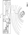
- FIG. 7 shows the LiDAR system 602 in operation.
- the AV 100 receives both camera system output 504c in the form of an image 702 and LiDAR system output 504a in the form of LiDAR data points 704.
- the data processing systems of the AV 100 compares the image 702 to the data points 704.
- a physical object 706 identified in the image 702 is also identified among the data points 704. In this way, the AV 100 perceives the boundaries of the physical object based on the contour and density of the data points 704.
- FIG. 8 shows the operation of the LiDAR system 602 in additional detail.
- the AV 100 detects the boundary of a physical object based on characteristics of the data points detected by the LiDAR system 602.
- a flat object such as the ground 802
- the ground 802 will reflect light 804a-d emitted from a LiDAR system 602 in a consistent manner.
- the ground 802 will reflect light back to the LiDAR system 602 with the same consistent spacing.
- the LiDAR system 602 will continue to detect light reflected by the next valid ground point 806 if nothing is obstructing the road.
- the AV 100 can determine that the object 808 is present.
- FIG. 9 shows a block diagram 900 of the relationships between inputs and outputs of a planning module 404 (e.g., as shown in FIG. 4 ).
- the output of a planning module 404 is a route 902 from a start point 904 (e.g., source location or initial location), and an end point 906 (e.g., destination or final location).
- the route 902 is typically defined by one or more segments. For example, a segment is a distance to be traveled over at least a portion of a street, road, highway, driveway, or other physical area appropriate for automobile travel.
- the route 902 includes "off-road" segments such as unpaved paths or open fields.
- a planning module also outputs lane-level route planning data 908.
- the lane-level route planning data 908 is used to traverse segments of the route 902 based on conditions of the segment at a particular time. For example, if the route 902 includes a multi-lane highway, the lane-level route planning data 908 includes trajectory planning data 910 that the AV 100 can use to choose a lane among the multiple lanes, e.g., based on whether an exit is approaching, whether one or more of the lanes have other vehicles, or other factors that vary over the course of a few minutes or less.
- the lane-level route planning data 908 includes speed constraints 912 specific to a segment of the route 902. For example, if the segment includes pedestrians or un-expected traffic, the speed constraints 912 may limit the AV 100 to a travel speed slower than an expected speed, e.g., a speed based on speed limit data for the segment.
- the inputs to the planning module 404 includes database data 914 (e.g., from the database module 410 shown in FIG. 4 ), current location data 916 (e.g., the AV position 418 shown in FIG. 4 ), destination data 918 (e.g., for the destination 412 shown in FIG. 4 ), and object data 920 (e.g., the classified objects 416 as perceived by the perception module 402 as shown in FIG. 4 ).
- the database data 914 includes rules used in planning. Rules are specified using a formal language, e.g., using Boolean logic. In any given situation encountered by the AV 100, at least some of the rules will apply to the situation.
- a rule applies to a given situation if the rule has conditions that are met based on information available to the AV 100, e.g., information about the surrounding environment. Rules can have priority. For example, a rule that says, "if the road is a freeway, move to the leftmost lane” can have a lower priority than "if the exit is approaching within a mile, move to the rightmost lane.”
- FIG. 10 shows a directed graph 1000 used in path planning, e.g., by the planning module 404 ( FIG. 4 ).
- a directed graph 1000 like the one shown in FIG. 10 is used to determine a path between any start point 1002 and end point 1004.
- the distance separating the start point 1002 and end point 1004 may be relatively large (e.g., in two different metropolitan areas) or may be relatively small (e.g., two intersections abutting a city block or two lanes of a multi-lane road).
- the directed graph 1000 has nodes 1006a-d representing different locations between the start point 1002 and the end point 1004 that could be occupied by an AV 100.
- the nodes 1006a-d represent segments of roads.
- the nodes 1006a-d represent different positions on that road.
- the directed graph 1000 includes information at varying levels of granularity.
- a directed graph having high granularity is also a subgraph of another directed graph having a larger scale.
- a directed graph in which the start point 1002 and the end point 1004 are far away (e.g., many miles apart) has most of its information at a low granularity and is based on stored data, but also includes some high granularity information for the portion of the graph that represents physical locations in the field of view of the AV 100.
- the nodes 1006a-d are distinct from objects 1008a-b which cannot overlap with a node.
- the objects 1008a-b when granularity is low, represent regions that cannot be traversed by automobile, e.g., areas that have no streets or roads.
- the objects 1008a-b represent physical objects in the field of view of the AV 100, e.g., other automobiles, pedestrians, or other entities with which the AV 100 cannot share physical space.
- some or all of the objects 1008a-b are a static objects (e.g., an object that does not change position such as a street lamp or utility pole) or dynamic objects (e.g., an object that is capable of changing position such as a pedestrian or other car).
- static objects e.g., an object that does not change position such as a street lamp or utility pole
- dynamic objects e.g., an object that is capable of changing position such as a pedestrian or other car.
- the nodes 1006a-d are connected by edges 1010a-c. If two nodes 1006a-b are connected by an edge 1010a, it is possible for an AV 100 to travel between one node 1006a and the other node 1006b, e.g., without having to travel to an intermediate node before arriving at the other node 1006b. (When we refer to an AV 100 traveling between nodes, we mean that the AV 100 travels between the two physical positions represented by the respective nodes.)
- the edges 1010a-c are often bidirectional, in the sense that an AV 100 travels from a first node to a second node, or from the second node to the first node.
- edges 1010a-c are unidirectional, in the sense that an AV 100 can travel from a first node to a second node, however the AV 100 cannot travel from the second node to the first node.
- Edges 1010a-c are unidirectional when they represent, for example, one-way streets, individual lanes of a street, road, or highway, or other features that can only be traversed in one direction due to legal or physical constraints.
- the planning module 404 uses the directed graph 1000 to identify a path 1012 made up of nodes and edges between the start point 1002 and end point 1004.
- An edge lOlOa-c has an associated cost 1014a-b.
- the cost 1014a-b is a value that represents the resources that will be expended if the AV 100 chooses that edge.
- a typical resource is time. For example, if one edge 1010a represents a physical distance that is twice that as another edge 1010b, then the associated cost 1014a of the first edge 1010a may be twice the associated cost 1014b of the second edge 1010b. Other factors that affect time include expected traffic, number of intersections, speed limit, etc. Another typical resource is fuel economy. Two edges 1010a-b may represent the same physical distance, but one edge 1010a may require more fuel than another edge 1010b, e.g., because of road conditions, expected weather, etc.
- the planning module 404 When the planning module 404 identifies a path 1012 between the start point 1002 and end point 1004, the planning module 404 typically chooses a path optimized for cost, e.g., the path that has the least total cost when the individual costs of the edges are added together.
- FIG. 11 shows a block diagram 1100 of the inputs and outputs of a control module 406 (e.g., as shown in FIG. 4 ).
- a control module operates in accordance with a controller 1102 which includes, for example, one or more processors (e.g., one or more computer processors such as microprocessors or microcontrollers or both) similar to processor 304, short-term and/or long-term data storage (e.g., memory random-access memory or flash memory or both) similar to main memory 306, ROM 1308, and storage device 210, and instructions stored in memory that carry out operations of the controller 1102 when the instructions are executed (e.g., by the one or more processors).
- processors e.g., one or more computer processors such as microprocessors or microcontrollers or both
- short-term and/or long-term data storage e.g., memory random-access memory or flash memory or both
- main memory 306, ROM 1308, and storage device 210 e.g., main memory
- the controller 1102 receives data representing a desired output 1104.
- the desired output 1104 typically includes a velocity, e.g., a speed and a heading.
- the desired output 1104 can be based on, for example, data received from a planning module 404 (e.g., as shown in FIG. 4 ).
- the controller 1102 produces data usable as a throttle input 1106 and a steering input 1108.
- the throttle input 1106 represents the magnitude in which to engage the throttle (e.g., acceleration control) of an AV 100, e.g., by engaging the steering pedal, or engaging another throttle control, to achieve the desired output 1104.
- the throttle input 1106 also includes data usable to engage the brake (e.g., deceleration control) of the AV 100.
- the steering input 1108 represents a steering angle, e.g., the angle at which the steering control (e.g., steering wheel, steering angle actuator, or other functionality for controlling steering angle) of the AV should be positioned to achieve the desired output 1104.
- the controller 1102 receives feedback that is used in adjusting the inputs provided to the throttle and steering. For example, if the AV 100 encounters a disturbance 1110, such as a hill, the measured speed 1112 of the AV 100 is lowered below the desired output speed. In an embodiment, any measured output 1114 is provided to the controller 1102 so that the necessary adjustments are performed, e.g., based on the differential 1113 between the measured speed and desired output.
- the measured output 1114 includes measured position 1116, measured velocity 1118, (including speed and heading), measured acceleration 1120, and other outputs measurable by sensors of the AV 100.
- information about the disturbance 1110 is detected in advance, e.g., by a sensor such as a camera or LiDAR sensor, and provided to a predictive feedback module 1122.
- the predictive feedback module 1122 then provides information to the controller 1102 that the controller 1102 can use to adjust accordingly. For example, if the sensors of the AV 100 detect ("see") a hill, this information can be used by the controller 1102 to prepare to engage the throttle at the appropriate time to avoid significant deceleration.
- FIG. 12 shows a block diagram 1200 of the inputs, outputs, and components of the controller 1102.
- the controller 1102 has a speed profiler 1202 which affects the operation of a throttle/brake controller 1204.
- the speed profiler 1202 instructs the throttle/brake controller 1204 to engage acceleration or engage deceleration using the throttle/brake 1206 depending on, e.g., feedback received by the controller 1102 and processed by the speed profiler 1202.
- the controller 1102 also has a lateral tracking controller 1208 which affects the operation of a steering controller 1210.
- the lateral tracking controller 1208 instructs the steering controller 1204 to adjust the position of the steering angle actuator 1212 depending on, e.g., feedback received by the controller 1102 and processed by the lateral tracking controller 1208.
- the controller 1102 receives several inputs used to determine how to control the throttle/brake 1206 and steering angle actuator 1212.
- a planning module 404 provides information used by the controller 1102, for example, to choose a heading when the AV 100 begins operation and to determine which road segment to traverse when the AV 100 reaches an intersection.
- a localization module 408 provides information to the controller 1102 describing the current location of the AV 100, for example, so that the controller 1102 can determine if the AV 100 is at a location expected based on the manner in which the throttle/brake 1206 and steering angle actuator 1212 are being controlled.
- the controller 1102 receives information from other inputs 1214, e.g., information received from databases, computer networks, etc.
- a computer system controls the operation of a fleet of autonomous vehicles.
- a computer system can deploy autonomous vehicles to one or more locations or regions, assign transportation tasks to each of the autonomous vehicles (e.g., pick up and transport passengers, pick up and transport cargo, etc.), assign maintenance tasks to each of the autonomous vehicles (e.g., charge their batteries at charging stations, receive repairs at a service station, etc.), and/or assign other tasks to each of the autonomous vehicles.
- transportation tasks to each of the autonomous vehicles e.g., pick up and transport passengers, pick up and transport cargo, etc.
- maintenance tasks e.g., charge their batteries at charging stations, receive repairs at a service station, etc.
- FIG. 13 shows an example computer system 1300 for controlling the operation of a fleet of autonomous vehicles 1302a-d.
- the computer system 1300 is remote from each of the autonomous vehicle 1302a-d, and communicates with the autonomous vehicles 1302a-d (e.g., via a wireless communications network).
- the computer system 1300 is implemented in a similar manner as the remote servers 136 described with respect to FIG. 1 and/or the cloud computing environment 300 described with respect to FIGS. 1 and 3 .
- one or more of the autonomous vehicles 1302a-d are implemented in a similar manner as the autonomous vehicle 100 described with respect to FIG. 1A .
- the geographical region 1304 can correspond to a particular political region (e.g., a particular country, state, county, province, city, town, borough, or other political region), a particular pre-defined region (e.g., a region having particular pre-defined boundaries such as a software determined geo-fenced area), a transiently-defined region (e.g., a region having dynamic boundaries such as a group of streets affected by dense traffic), or any other region.
- a particular political region e.g., a particular country, state, county, province, city, town, borough, or other political region
- a particular pre-defined region e.g., a region having particular pre-defined boundaries such as a software determined geo-fenced area
- a transiently-defined region e.g., a region having dynamic boundaries such as a group of streets affected by dense traffic
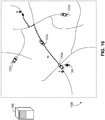
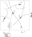
- a user 1306 positioned at a location "A" wishes to travel to a location "B" in an autonomous vehicle.
- the user 1306 transmits a request 1308 to the computer system 1300 (e.g., via a mobile device 1310, such as a smartphone, tablet computer, or wearable computing device).
- the request 1308 includes one or more data items indicating the user's desired pick up location (e.g., the current location of the user or another pick up location specified by the user), a desired pick up time, and/or a desired destination location (e.g., a destination location specified by the user).
- the computer system 1300 selects one of the autonomous vehicles 1302a-d to fulfill the request.
- the computer system 1300 considers one or more different criteria in selecting an autonomous vehicle.
- the computer system 1300 can determine which of the autonomous vehicles is currently available (e.g., is not currently assigned to transport a passenger and/or cargo, and/or is not actively transporting a passenger and/or or cargo), and select one of the available autonomous vehicles for assignment to the user 1306.
- the computer system 1300 can also consider whether an autonomous vehicle is currently unavailable, but is anticipated to be available in the future (e.g., an autonomous vehicle that is currently assigned to another task, but is anticipated to complete its task sufficiently soon for subsequent assignment to the user 1306 and arrival at the user's desired pick up location at the desired time). In some embodiments, the computer system 1300 prioritizes certain autonomous vehicles for selection over others (e.g., based on the proximity of the autonomous vehicles with respect to the user 1306, the orientation or heading of the autonomous vehicles with respect to the user 1306, time and/or ease in which the autonomous vehicles can reach the user 1306, the ability for autonomous vehicles to navigate to users while minimally affecting traffic flows, etc.).
- the computer system 1300 selects the autonomous vehicle 1302a for assignment to the user 1306.
- the computer system 1300 transmits a command signal 1400 to the autonomous vehicle 1302a instructing the autonomous vehicle 1302a to fulfill the user's request.
- the command signal 1400 includes one or more data items indicating a pick up location for the user 1306 (e.g., the pick up location specified by the user), a pick up time, and/or the destination location (e.g., the destination location specified by the user).
- the autonomous vehicle 1302a navigates to the specified pick up location (e.g., the location A along a path P1) to pick up the user 1306 (along with her travel party and/or any cargo, if applicable) at the specified time.
- the autonomous vehicle 1302a navigates to the destination location (e.g., the location B along a path P2).
- the autonomous vehicle 1302a stops, and allows the user 106 to disembark.
- the autonomous vehicle 1302a is then made available for use by others (e.g., to transport one or more other users and/or cargo).
- the path of the autonomous vehicle 1302a can be determined by the autonomous vehicle 1302a itself and/or by the computer system 1300. For instance, in some implementations, the autonomous vehicle 1302a determines a path of travel based on its current location and its goal location (e.g., the specified pick up location and/or the specified destination location). In some implementations, the computer system 1300 determines a path of travel for the autonomous vehicle 1302a, and transmit the determined path to the autonomous vehicle 1302a (e.g., in the command signal 1400, or some other data transmission).
- the operation of the computer system 1300 can provide various technical benefits.
- the computer system 1300 can facilitate the automatic operation of a fleet of autonomous vehicles, enabling autonomous vehicles to fulfill requests in an automated manner without human intervention.
- the computer system can automatically control the operation of the fleet of autonomous vehicles such that requests are fulfilled in an efficient and effective manner (e.g., by reducing the amount of time that autonomous vehicles are idle, and increasing the speed at which requests are fulfilled).
- an autonomous vehicle is used to transport cargo (e.g., packages, items, or other objects) instead of or in addition to transporting passengers.
- a user can transmit a request to the computer system 1300 indicating a desired pick up location (e.g., a location of cargo), a desired pick up time, and/or a desired destination location (e.g., a destination location where the cargo is to be delivered).
- the computer system 1300 assigns an autonomous vehicle to transport the cargo, and transmit command signals to the autonomous vehicle specifying the pickup and destination locations and pick up time (e.g., in a similar manner as described with respect to FIGS. 13-16 ).
- two or more autonomous vehicles are positioned at a similar location at a similar time, and/or have a similar destination location.
- the computer system 1300 can provide different paths of travel to one or more of the autonomous vehicles, such that their impact on vehicular traffic in the transportation network is reduced. For instance, if multiple autonomous vehicles were to be assigned an identical route to a destination location, each of the autonomous vehicles would travel along the same roads of the transportation network in close session. This can potentially increase the congestion of those roads, and decrease the effective travel speed across them.
- one or more autonomous vehicles can be assigned to an alternative route to the destination, such that their impact is not concentrated to a single route (e.g., as it instead spread among several different roads).
- two autonomous vehicles 1302a and 1302b are positioned at a similar location (e.g., in proximity to a pick up location A) and have been assigned to travel to a similar destination location (e.g., to a specified location B).
- the computer system 1300 can transmit a first command signal 1700a to a first autonomous vehicle 1302a including instructions to navigate to the destination location along a path PI, and a second command signal 1700b to a second autonomous vehicle 1302b including instructions to navigate to the destination location along a path P2.
- Paths P1 and P2 are different from one another, and utilize at least some different roads from one another. Accordingly, the impact on traffic flows and route conditions of the autonomous vehicles is spread among different routes, rather than concentrated on a single route.
- a computer system 1300 estimates a future demand for use of autonomous vehicles, and preemptively direct autonomous vehicles to certain locations to better meet the estimated demand. For instance, the computer system 1300 can direct autonomous vehicles to certain locations, even if it has not yet received a request from a user associated with that location. In some embodiments, the computer system 1300 estimates a relatively higher future demand for autonomous vehicles at a particular location, and direct autonomous vehicles to that location from locations having a relatively lower current and/or estimated future demand.
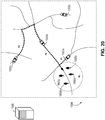
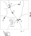
- FIG. 18 shows a region 1304 having several autonomous vehicles 1302a-d and several users 1800a-d.
- none of the users 1800a-d have yet submitted a request for use of an autonomous vehicle.
- the computer system 1300 has estimated that there will be a future demand in a region Rl.
- the computer system 1300 transmits command signals to some or all of the autonomous vehicles 1302a-d to reposition those autonomous vehicles in anticipation of the estimated future demand. For instance, as shown in FIG. 19 , the computer system 1300 can determine that three additional vehicles are needed in the region Rl to fulfill the estimated demand, and transmit command signals 1900 to each of the autonomous vehicles 1302a-c instructing them to travel to the region Rl.
- the autonomous vehicles 1302a-c navigate to the region Rl (e.g., along paths PI, P2, and P3).
- the paths PI, P2, and P3 are determined by the autonomous vehicles themselves.
- some or all of the paths PI, P2, and P3 are determined by the computer system 1300 and transmitted to a respective autonomous system (e.g., as a part of the command signals 1900 or some other data transmission).
- the computer system 1300 can estimate future demand using a variety of different techniques.
- the computer system 1300 collects current and/and historical information regarding one or more users and their behavior, one or more autonomous vehicles and their operation, the environment of the users and/or autonomous vehicles, the usage of the autonomous vehicles, and other factors that can potentially indicate or influence future demand. Using this information as inputs, the computer system 1300 can generate a predictive model to estimate the future demand with respect to one or more particular regions or locations and with respect to one or more particular spans or points in item.
- the computer system 1300 can collect user profile data from one or more of its users.
- User profile data can include any information regarding one or more users.
- user profile data can include information regarding the current location of one or more users (e.g., based on location information provided by a mobile device of each user).
- User profile data can also include demographic information regarding one or more users (e.g., one or more demographic indicators, such as an age, gender, occupation, are or location of residence, etc. of each user).
- the user profile data can further includes user's social media data.
- the user profile data can also include information regarding the historical behavior of one or more users (e.g., previous locations of the user and the associated times, previous trips taken by the user and the associated times, etc.)
- user profile data includes information regarding one or more trends associated with a user.
- the user profile data can include information regarding a user's a tendency to travel between certain locations under certain conditions (e.g., time of day, day of week, month, season, etc.).
- the user profile can include information regarding a user's trends to request use of an autonomous vehicle under certain conditions (e.g., time of day, day of week, month, season, weather, traffic, etc.).
- user profile data could include information indicating a user's frequency of travel and/or changes to his frequency of travel (e.g., increasing over time or decreasing over time). Further, the user profile data can also include information regarding the preferences of one or more users (e.g., indicating that the user prefers a particular types of vehicles for travel, prefers a particular level of service for travel, etc.). The user profile data can include contact information for one or more users (e.g., phone number, mailing address, e-mail address, residential address, business address, etc.), In some implementations, user profile data can be collected from one or more devices associated with one or more users (e.g., mobile devices or other devices operated by the users).
- devices associated with one or more users e.g., mobile devices or other devices operated by the users.
- Vehicle telemetry data can include information regarding the current operation of one or more autonomous vehicles (e.g., an autonomous vehicle's location, speed, heading, orientation, route, path, etc.). Vehicle telemetry data can also include information regarding the historical behavior of one or more users (e.g., the previous locations of the autonomous and the associated time, previous routes taken by the autonomous vehicle and the associated time, etc.). Vehicle telemetry data can include information regarding the current or historical environmental conditions observed by one or more autonomous vehicles (e.g., a traffic condition of a road observed by the autonomous vehicle, a closure or an obstruction of a road observed by the autonomous vehicle, an object or hazard observed by the autonomous vehicle, etc.).
- a traffic condition of a road observed by the autonomous vehicle e.g., a closure or an obstruction of a road observed by the autonomous vehicle, an object or hazard observed by the autonomous vehicle, etc.
- the computer system 1300 can collect event information regarding one or more events that have occurred in the past, are currently occurring, and/or are expected to occur in the future.
- Example events include civic events (e.g., parades, sports events, festivals, concerts, etc.), traffic events (e.g., road closures, detours, congestion, change in a direction of traffic flow, etc.), and weather events (e.g., rain, flooding, wind, fog, lightning, snow, ice, sleet, etc.), among others.
- the computer system 1300 collects historical information regarding one or more events (e.g., information describing the occurrence of an event, the time at which in occurred, and the location of occurrence).
- the computer system 1300 collects information regarding one or more currently occurring events (e.g., information describing the occurrence of an event, the time of occurrence, and the location of occurrence). In some embodiments, the computer system 1300 collects information regarding one or more planned events in the future (e.g., information describing the anticipated occurrence of an event, the anticipated time of occurrence, and the anticipated location of occurrence). In some embodiments, the computer system 1300 estimates or predicts the future occurrence of one or more events (e.g., based on a predictive model using collected event information as inputs). In some implementations, event information is collected from one or more devices associated with one or more users, the autonomous vehicles, and/or from third-parties (e.g., a transportation authority, weather information service, traffic information service, governmental agency or organization, etc.).
- third-parties e.g., a transportation authority, weather information service, traffic information service, governmental agency or organization, etc.
- the computer system 1300 can generate a statistical model (e.g., a predictive model, a stochastic model, a regression model etc.) to estimate the future demand with respect to one or more particular regions or locations and with respect to one or more particular spans or points in item.
- a statistical model e.g., a Bayesian statistical model
- a statistical model can be generated based on the user profile data, the vehicle telemetry data, event information, and other information collected by the computer system 1300.
- the computer system 1300 can identify one or more factors or conditions correlating with an increased or decreased likelihood that a user will submit a request for use of an autonomous vehicle at a particular region or location, and at a particular time. Using this information, the computer system 1300 can identify particular regions or locations that are associated with a higher likelihood of having a future user request at particular times. Similarly, future demand estimates can be generated using stochastic differential equations describing demand evolution and generation across a range of different locations, regions, and/or time, and/or these estimates can be aggregated together to determine an overall estimated future demand.
- the region R1 corresponds to the geographical location of several users 1800a-d.
- this is merely an illustrative example.
- a geographical concentration of users can be but one factor in estimating a future demand for use of the autonomous vehicles.
- the computer system 1300 can estimate future demand with respect to a more specific geographical area (e.g., a specific location) or more general geographical area (e.g., a larger geographical region).
- a more specific geographical area e.g., a specific location
- more general geographical area e.g., a larger geographical region
- the computer system 1300 can estimate future with respect to a relatively specific range of time (e.g., an instantaneous point in time) or a relatively broader range of time (e.g., a range of time on the order of seconds, minutes, hours, days, weeks, months, seasons, years, or other ranges of time). Further still, the computer system 1300 can estimate future demand for a relatively nearer time in the future (e.g., on the order of seconds or minutes in the future), to for a relatively further time in the future (e.g., on the order of hours, days, weeks, months, or years in the future). Further, upon estimating future demand, the computer system 1300 can delay transmitting command signals to autonomous vehicles in accordance with the estimated future time of that demand. For instance, if the computer system 1300 estimates that demand will increase at a particular location several hours from the current time, the computer system 1300 can delay transmitting commands with repositioning instructing to autonomous vehicles until closer to the estimated time.
- a relatively specific range of time e.g
- the computer system 1300 instructs one or more autonomous vehicles to "roam" in a particular region or along a particular path (e.g., to search for potential users or cargo to transport).
- FIG. 21 shows a region 1304 having several autonomous vehicles 1302a-d and several users 2100a-d.
- none of the users 2100a-d have yet submitted a request for use of an autonomous vehicle.
- the autonomous vehicle 1302b is not actively transporting a user or cargo, and has not yet been assigned to transport a user or cargo.
- the computer system 1300 transmits a command signal 2102 to the autonomous vehicle 1302b instructing the autonomous vehicle 1302b to "roam" along a path P1.
- the autonomous vehicle 102B navigates the path P1 (e.g., until it is assigned to transport a user or cargo, or assigned to some other task).
- the computer system 1300 specifies the roaming path based on information regarding the known and/or predicted locations of users. For example, the computer system 1300 can collect user profile data including the current locations of one or more users. Based on this information, the computer system 1300 can define a roaming path such that an autonomous vehicle travels into a proximity of one or more of those users (e.g., in anticipation of a potential request). As another example, the computer system 1300 can use a statistical model to estimate a future request by one or more users at particular locations. Based on this information, the computer system 1300 can define a roaming path such that an autonomous vehicle travels into a proximity of one or more of those locations (e.g., in anticipation of a potential request). In some embodiments, the computer system 1300 can generate different roaming paths for different autonomous vehicles such that each autonomous vehicle roams in a different region and/or along a different path (e.g., to reduce redundancy).
- the computer system 1300 instructs one or more autonomous vehicles to "idle” at a particular location (e.g., to await a potential user or cargo to transport, or assignment to another task).
- FIG. 23 shows a region 1304 having several autonomous vehicles 1302a-d.
- the autonomous vehicle 1302b is not actively transporting a user or cargo, and has not yet been assigned to transport a user or cargo.
- the computer system 1300 transmits a command signal 2302 to the autonomous vehicle 1302b instructing the autonomous vehicle 1302b to navigate to a location A and idle at that location (e.g., until the autonomous vehicle is assigned another task).
- the autonomous vehicle 102B navigates to the location A along a path P1 and remains that that location (e.g., until it is assigned to transport a user or cargo, or assigned to some other task).
- the autonomous vehicle 102B identifies and navigates to a safe idling location at or in proximity to the specified location (e.g., a parking space, designed waiting area, etc.).
- the computer system 1300 specifies an idling location based on information regarding the known and/or predicted locations of users. For example, the computer system 1300 can collect user profile data including the current locations of one or more users. Based on this information, the computer system 1300 can identify an idling location that is in proximity of one or more of those users (e.g., in anticipation of a potential request). As example, the computer system 1300 can use a statistical model to estimate a future request by one or more users at particular locations. Based on this information, the computer system 1300 can define an idling location that is in proximity of one or more of those locations (e.g., in anticipation of a potential request). In some embodiments, the computer system 1300 generates different idling locations for different autonomous vehicles such that each autonomous vehicle idles a different region (e.g., to reduce redundancy).
- a user can request an autonomous vehicle by physically approaching an idling autonomous vehicle, and submitting a request identifying that autonomous vehicle. For example, as shown in FIG. 25 , a user 2304 can approach the idling autonomous vehicle 1302b and submit a request 2306 to reserve the autonomous vehicle 1302b for use (e.g., using her mobile device 2308).
- the request 2306 includes one or more data items identifying the autonomous vehicle 1302b.
- the user can input an identifier associated with the autonomous vehicle 102B (e.g., an alphanumeric sequence displayed on the autonomous vehicle 1302b, such as a serial number or vehicle name), and the identifier can be included in the request 2306.
- the autonomous vehicle can include a visually distinctive graphical element (e.g., a bar code, QR code, or other identifier), and the user can capture a video or image of the graphical element (e.g., using a camera on her mobile device 2308).
- the graphical element and/or a representation of the graphical element e.g., an underlying identifier encoded in the graphical element
- the autonomous vehicle includes a proximity based communications transceiver (e.g., a Bluetooth or near-field communications module).
- the user can select the autonomous vehicle 1302b by placing her mobile device 2308 (having its own communications transceiver) in proximity to the communications transceiver of the autonomous vehicle 1302b.
- the communications transceiver of the autonomous vehicle 1302b can transmit an identifier of the autonomous vehicle 1302b to the mobile device 2308. The identifier can be included in the request 2306.
- the user selects the autonomous vehicle 1302b by placing her mobile device 2308 in proximity to the communications transceiver of the autonomous vehicle 1302b.
- the mobile device 2308 transmits an identifier associated with the user 2304 (e.g., a user name and/or other access credentials) to the autonomous vehicle 1302b.
- the autonomous vehicle 1302b can transmit the request 2306 to the computer system 1300 (e.g., on behalf of the user 2304).
- the request can include one or more data items identifying the user and/or the autonomous vehicle.
- the user selects the autonomous vehicle 1302b by using a biometric scanner (e.g., an iris scanner, a fingerprint reader, or a facial recognition system) to verify the user's identity.
- a user that has not hailed/utilized autonomous vehicles previously is directed to a service sign-up internet link/webpage/website/microsite/app download link on their mobile device upon attempting to select the autonomous vehicle.
- the computer system 1300 can assign the autonomous vehicle 102B for use by the user 2304 and transport the user to a desired location (e.g., in a similar manner as described with respect to FIGS. 13-16 ). For instance, upon reserving the autonomous vehicle 1302b for use, the user 2304 can input a desired destination and board the autonomous vehicle 1302b. In response, the autonomous vehicle 1302b can navigate to the specified location (e.g., on its own accord or based on information provided by the computer system 1300), and allow the user 2304 is disembark.
- the specified location e.g., on its own accord or based on information provided by the computer system 1300
- the computer system 1300 instructs one or more autonomous vehicles to travel to a particular location to receive maintenance and/or charge its batteries.
- the computer system 1300 can instruct an autonomous vehicle to travel to a charging station and recharge its batteries for a period of time.
- the computer system 1300 instructs an autonomous vehicle to travel to a charging station based on vehicle telemetry data. For instance, if a low battery charge condition or depleted battery condition is detected (e.g., based on sensor data included in the vehicle telemetry data), the computer system 1300 can instruct the autonomous vehicle to travel to a charging station to recharge its batteries such that the autonomous vehicle can continue operation.
- FIG. 26 shows a region 1304 having several autonomous vehicles 1302a-d.
- the autonomous vehicle 1302c has a low battery charge, and will need to recharge its batteries to sustain operation.
- the computer system 1300 transmits a command signal 2600 to the autonomous vehicle 1302 instructing the autonomous vehicle 1302c to navigate to a recharging station located at a location A and recharge its batteries.
- the autonomous vehicle 102C navigates to the location A along a path P1 and remains that that location (e.g., until its batteries have been recharged, or until it has been assigned another task).
- the computer system 1300 prioritizes the performance of certain tasks over the performance of other tasks. For instance, the computer system 1300 can prioritize fulfilling requests for transporting users (e.g., to convey users between different locations) over requests for transporting cargo (e.g., to convey cargo between different locations). Further, when an autonomous vehicle is not actively transporting users and/or cargo, and has not yet been assigned to transport users and/or cargo, the computer system 1300 can instruct the autonomous vehicle to perform various tasks while it waits for a potential request.
- requests for transporting users e.g., to convey users between different locations
- cargo e.g., to convey cargo between different locations
- the computer system 1300 can reposition the autonomous vehicle to a different region or location in anticipation of a request, instruct the autonomous vehicle to idle at a particular location, instruct the autonomous vehicle to roam at a particular region or along a particular path, instruct the autonomous vehicle to recharge its batteries at a charging station, instruct the autonomous vehicle to receive maintenance at a service station, and/or perform some other task.
- This is beneficial, for example, as it prioritizes the transportation of users and/or cargo (e.g., thereby improving the effectiveness and responsiveness of the fleet of autonomous vehicles), while reducing wastefulness or unbeneficial inactivity in the autonomous vehicles while they are not transporting users and/or cargo (e.g., thereby improve the efficiency of operation of the fleet of autonomous vehicles).
- the computer system 1300 prioritizes the transportation of certain users and/or cargo over others.
- each request can be associated with a particular level of service (e.g., "economy,” “standard,” “premium,” etc.), each having a different priority level.
- Higher priority requests can take precedence over lower priority requests (e.g., such that they are more likely to be fulfilled first).
- higher levels of service are associated with higher fares or rates charged to the user.
- the computer system 1300 can prioritize the transportation of users and/or cargo to certain destinations over other destinations.
- transportation to certain destinations e.g., airports
- transportation to other destinations e.g., the beach
- the computer system 1300 can thus prioritize certain requests such that certain destinations take precedence over others.
- an autonomous vehicle is assigned to a single request at a time (e.g., to transport a single user along with her travel party and/or any cargo at a time).
- a time e.g., to transport a single user along with her travel party and/or any cargo at a time.
- an autonomous vehicle are concurrently assigned to multiple different requests a time. For instance, an autonomous vehicle can be assigned to pick up a first user (and her travel party) having a first request, pick up a second user (along with her travel party and/or any cargo, if applicable) having a second request, transport both the first user and the second user concurrently, and individually drop each of the users off at their respective destinations (e.g., a "carpooling" arrangement).
- the computer system 1300 assigns autonomous vehicles based on demand. For example, if autonomous vehicles are in low demand, the computer system 1300 can assign each request a dedicated autonomous vehicle (e.g., such the user and her party do not have to ride with others). However, if autonomous vehicles are in high demand, the computer system 1300 can concurrently assign multiple requests the same autonomous vehicle (e.g., to improve the effectiveness and efficiency of the fleet of autonomous vehicles). In some embodiments, each request is associated with a particular level of service (e.g., "economy,” "standard,” “premium,” etc.), each having a different priority level. Higher priority requests can take precedence over lower priority requests, such that they are more likely to be assigned a dedicated autonomous vehicle. In some embodiments, higher levels of service are associated with higher fares or rates charged to the user.
- level of service e.g., "economy,” "standard,” “premium,” etc.
- the computer system 1300 offers a user a shared or carpooled ride with one or more other requestors in exchange for a shorter wait time. If the user accepts the offer, the computer system 1300 can concurrently assign the user's request and another user's request to the same autonomous vehicle. If the user declines, the computer system 1300 can assign the user's request to a dedicated autonomous vehicle when an autonomous vehicle is made available for dedicated use.
- the computer system 1300 estimates a first length of time associated with fulfilling the user's request using a shared or carpool ride and a second length of time associated with fulfilling the user's request using a dedicated ride, and provide this information to the user (e.g., to assist the user in coming to a decision).
- the computer system 1300 determines a priority metric for each user and/or request, and prioritize the fulfillment of requests based on that metric.
- a priority metric can be, for example, a score or rank associated with each user and/or request.
- Priority metrics can be determined based on one or more of the factors discussed above (e.g., the task associated with the request, the pick up and/or destination locations associated with the request, a level of service associated with the user and/or request, a demand for use of the autonomous vehicles, etc.).
- the computer system 1300 can estimate a future demand for direct autonomous vehicles in a particular region, and direct autonomous vehicles to that location to meet the predicted future demand. In some embodiments, the computer system 1300 does so by repositioning autonomous vehicles from a region of relatively lower demand or estimated future demand to a region of relatively higher demand or estimated future demand.
- FIG. 28 shows a first region 1304 having several autonomous vehicles 1302a-d and a second region 2800 having an autonomous vehicle 2802.
- the different regions 1304 and 2800 can correspond to different political regions, different pre-defined regions, different transiently-defined region, and/or any other different regions.
- the computer system 1300 has estimated that there will be a relatively lower future demand for use of autonomous vehicles in the first region 1304, and a relatively higher future demand for use of autonomous vehicles in the second region 2800 (e.g., based on a statistical model). Further, the computer system 1300 can determine that additional autonomous vehicles are required in the second region 2800 to fulfill the estimated demand in that region, while there are an excess of autonomous vehicles in the first region 1304 needed to fulfill the estimated demand in that region.
- the computer system 1300 transmits command signals 2804 to one or more of the autonomous vehicles in the region 1304 (e.g., the autonomous vehicles 1302a and 1302c) instructing them to navigate to the region 2800.
- the autonomous vehicles 1302a and 1302c transverse to the region 2800 (e.g., using a network of roads 2806 interconnecting the regions 1304 and 2800).
- the repositioned autonomous vehicles 1302a and 1302c can be assigned one or more tasks within the region 2800 (e.g., transport users and/or cargo, roam along a particular path, idle at a particular location, charge its batteries at a charging station, receive maintenance at a service station, etc.).
- a user can submit a request specifying a desired pick up location.
- a computer system transmits a command signal instructing an autonomous vehicle to navigate to that pick up location.
- the computer system identifies an alternative pick up location and suggest that location to the user. If the user accepts the alternative pick up location, the computer system can instruct both the user and the autonomous vehicle to meet at the alternative pick up location instead.
- a pick up location specified by a user may be unsafe or otherwise unsuitable for conducting pick ups (e.g., a location near a high volume of vehicle traffic, a location without a designed pick up area, a location near a fast flow of traffic, etc.).
- the computer system can determine a nearby alternative location that is safer for the user, and suggest that location for pick up instead.
- a pick up location specified by a user may be relatively inefficient.
- the specified pick up location may require that an autonomous vehicle take a cumbersome path to reach the location (or the location may be entirely inaccessible by an autonomous vehicle).
- the specified pick up location may require that an autonomous vehicle take a detour from a direct path between the autonomous vehicle's current location and the user's desired destination.
- the computer system can determine a nearby alternative location that is more efficient, and suggest that location for pick up instead.
- the alternative location can be a location that is more accessible to vehicles and/or a location that requires that the autonomous vehicle take fewer, shorter, or quicker detours to transport the user to the specified destination.
- FIG. 30 shows a region 1304 having several autonomous vehicles 1302a-d.
- a user 3000 positioned at a location "Al" wishes to travel to a location "B" in an autonomous vehicle.
- the user 3000 transmits a request 3002 to the computer system 1300 (e.g., in a similar manner as described with respect to FIG. 13 ).
- the request 3002 can include one or more data items indicating the user's desired pick up location (e.g., the current location of the user or another pick up location specified by the user), a desired pick up time, and/or a desired destination location (e.g., a destination location specified by the user).
- the computer system 1300 selects one of the autonomous vehicles 1302a-d to fulfill the request.
- the computer system 1300 has selected autonomous vehicle 1302a.
- the computer system 1300 determines a path P1 for the autonomous vehicle 1302a to first navigate to the pick up location A1, and then transverse to the destination location B.
- the path P1 is relatively inefficient, as it requires that the autonomous vehicle 1302a deviate from a direct path P2 to the destination B.
- the computer system 1300 determines an alternative pick up location A2 that is nearer to the direct path P2, and transmits a suggestion message 3004 to the user 3000 indicating the alternative location A2.
- the user can accept the alternative location A2 by transmitting a response message 3006 (e.g., indicating that the alternative location A2 is acceptable).
- the computer system 1300 transmits a command signal 3008 to the autonomous vehicle 1302a instructing the autonomous vehicle 1302a to fulfill the user's request by first picking up the user 3000 at the pick up location A2 (instead of at the originally specified location A2), and then transporting the user 3000 to the location B (e.g., along the path P2).
- the user 3000 has been notified of the new pick up location A2, the user 3000 can travel to the new pick up location A2 to meet the autonomous vehicle 1302a.
- the computer system also identifies an alternative destination location and suggest that destination location to the user. If the user accepts the alternative destination up location, the computer system can instruct the autonomous vehicle to drop off the user at the alternative destination location instead.
- a destination location specified by a user may be unsafe or otherwise unsuitable for conducting drop offs (e.g., a location near a high volume of vehicle traffic, a location without a designed pick up area, a location near a fast flow of traffic, etc.).
- the computer system can determine a nearby alternative location that is safer for the user, and suggest that location for drop offs instead.
- a pick up location specified by a user may be relatively inefficient.
- the specified destination location may require that an autonomous vehicle take a cumbersome path to reach the location (or the location may be entirely inaccessible by an autonomous vehicle).
- the computer system can determine a nearby alternative location that is more efficient, and suggest that location for drop off instead.
- the alternative location can be a location that is more accessible to vehicles.
- FIG. 34 shows a region 1304 having several autonomous vehicles 1302a-d.
- a user 3400 has boarded the autonomous vehicle 1302a and has specified that she wishes to be transported to a location A1.
- the computer system 1300 determines that the path to the destination location A1 is obstructed by a construction zone 3402, and identifies an alternative destination location A2 for drop off of the user 3400 (e.g., an accessible location in proximity to the originally specified location Al).
- the computer system 1300 transmits a suggestion message 3404 to the user 3400 indicating the alternative location A2.
- the user can accept the alternative location A2 by transmitting a response message 3406 (e.g., indicating that the alternative location A2 is acceptable).
- the acceptance may be indicated though the user's mobile device or some other computer device that includes a suitable input device installed in the autonomous vehicle.
- the computer system 1300 transmits a command signal 3408 to the autonomous vehicle 1302a instructing the autonomous vehicle 1302a to transport the user 3400 to the location A2 (instead of the originally specified location A1). The user then disembarks at location A2.
- a computer system manages the operation of a fleet of autonomous vehicles in conjunction with one or more additional modes of transportation (e.g., trains, subways, boats, airplanes, biking, walking, etc.). For instance, a user can submit a request for transportation between two locations. In response, the computer system can determine whether an autonomous vehicle can transport the user at least a portion of the way between the two locations, and whether other modes of transportation can also be used to transport the user. Based on this information, the computer system can generate a travel itinerary for the user identifying one or more different modes of transportation to the user to travel between the two locations.
- additional modes of transportation e.g., trains, subways, boats, airplanes, biking, walking, etc.
- the computer system can generate an itinerary identifying the autonomous vehicle as the sole mode of transportation, and instruct the autonomous vehicle to pick up the user at the specified location and transport the user to the specified destination.
- the user can refer to the itinerary to ensure that she meets the autonomous vehicle at the appropriate time and place.
- the computer system can generate an itinerary identifying the autonomous vehicle as a first mode of transportation for a first portion of the travel (e.g., between two waypoints defining a first leg of travel), and one or more other modes of transportation for other portions of the travel (e.g., between other waypoints defining other legs of travel). Further, the computer system can instruct the autonomous vehicle to pick up the user at a particular location (e.g., a first waypoint) and to transport the user to another location (e.g., a second waypoint). The user can refer to the itinerary to ensure that she meets the autonomous vehicle at the appropriate time and place to complete one leg of travel, and to correctly navigate using the other modes of transportation to complete the other legs of travel.
- the computer system generates a travel itinerary specifying multiple modes of transportation if an autonomous vehicle alone cannot transport the user the entirety of the way between the two locations (e.g., if the pick up location and/or the destination location is inaccessible to vehicles, or it is impractical to do so).
- the computer system generates a travel itinerary specifying multiple modes of transportation if the resulting travel time is shorter than that of an autonomous vehicle alone. For instance, due to traffic congestion between two locations, an autonomous vehicle alone might require an hour to transport the user between two locations. However, the use of an autonomous vehicle for a first leg of travel and a subway for a second leg of travel might reduce the travel time by 20 minutes. To save the user time, the computer system can generate a travel itinerary identifying these two different legs to the user, and instruct the autonomous vehicle to transport the user in accordance with the itinerary.
- one or more modes of transportation are public transportation (e.g., modes of transportation provided at least in part by a governmental body or authority).
- Examples forms of public transportation include buses, ferries, subways, and trains operated by a municipality, state, county, country, or other governmental body.
- FIG. 37 shows a region 1304 having an autonomous vehicle 1302a.
- the region 1304 also includes two train stations S1 and S2 interconnected by a rail network 3700.
- a user 3702 positioned at a location "A" wishes to travel to a location "B" in an autonomous vehicle.
- the user 3702 transmits a request 3704 to the computer system 1300 (e.g., in a similar manner as described with respect to FIG. 13 ).
- the request 3704 can include one or more data items indicating the user's desired pick up location (e.g., the current location of the user or another pick up location specified by the user), a desired pick up time, and/or a desired destination location (e.g., a destination location specified by the user).
- the autonomous vehicle 1302a cannot access the location B (e.g., due to a lack of contiguous roads between the locations A and B).
- the computer system 1300 determines that the autonomous vehicle 1302a alone is unable to transport the user, but determines that the user can successfully travel between locations A and B using a combination of an autonomous vehicle (e.g., from the location A to the station S1), a train (e.g., from the station S1 to the station S2), and walking (e.g., from the station S2 and the location B).
- This determination can be made, for example, using information collected by the computer system 1300 regarding each of the modes of transportation (e.g., based on user profile data, vehicle telemetry data, environmental data, event data, and other information).
- the computer system 1300 Based on this determination, the computer system 1300 generates a travel itinerary 3706 identifying, for each leg of travel, the mode of transportation used for that leg (e.g., autonomous vehicle, train, walking, etc.), and details regarding the leg of travel (e.g., a start point and end point for the leg, an estimated time of travel for the leg, an estimated start time and end time for the leg, etc.).
- This itinerary is transmitted to the user 3702 (e.g., to a mobile device of the user 3702) for reference during travel.
- the computer system 1300 generates a command signal 3708 instructing the autonomous vehicle 1302a to fulfill a leg of the user's travel (e.g., instructions to pick up the user 3702 at the location A, and transport the user 3702 to the station S1).
- a leg of the user's travel e.g., instructions to pick up the user 3702 at the location A, and transport the user 3702 to the station S1.
- a computer system can assign various tasks to one or more autonomous vehicles (e.g., transporting users and/or cargo, repositioning to different regions, roaming, idling, etc.).
- the autonomous vehicles automatically accepts each of the assigned tasks as they are received, and proceed to carry out the assigned tasks in an automated manner.
- one or more autonomous vehicles declines an assigned task.
- FIG. 39 shows a first fleet of autonomous vehicles 3900a and a second fleet of autonomous vehicles 3900b.
- the computer system 1300 can propose assignments to autonomous vehicles in each of the fleets, and allow the autonomous vehicles to accept or decline the tasks.
- tasks are automatically accepted or declined based on certain conditions (e.g., logical rules defined by the operators of each fleet).
- tasks are manually accepted or declined (e.g., based on human input).
- certain fleets of autonomous vehicles are prioritized for assignment over others. For instance, if the availability of autonomous vehicles from one fleet is sufficiently low (e.g., below a threshold level), autonomous vehicles from another fleet can be draw for service. As an example, a primary fleet can be assigned tasks to transport users and/or cargo in a particular region. If availability of autonomous vehicles from the primary fleet is sufficiently low, additional autonomous vehicles from a secondary fleet can be draw for service to meet the demand.
- different fleets of autonomous vehicles are controlled, operated, maintained, and/or operated by different business entities.
- several different business entities can each operate one or more autonomous vehicles in a particular region.
- a computer system 1300 can coordinate the operation of the autonomous vehicles across each of the fleets (e.g., to automatically assign tasks of each of the autonomous vehicles), while allowing each of the business entities individual control over the autonomous vehicles of its respective fleet (e.g., to accept or decline assigned tasks as desired).
- FIG. 40 shows an example process 4000 for controlling the operation of a fleet of autonomous vehicles.
- the process 4000 can be performed, at least in part, using one or more of the systems described herein (e.g., using one or more computer systems, AV systems, autonomous vehicles, etc.).
- a computer system receives vehicle telemetry data (step 4010).
- the vehicle telemetry data indicates a respective geographical location of each autonomous vehicle of a plurality of autonomous vehicles.
- vehicle telemetry data can include an indication of a speed of an autonomous vehicle of the plurality of autonomous vehicles, an indication of a location of an autonomous vehicle of the plurality of autonomous vehicles, an indication of a heading of an autonomous vehicle of the plurality of autonomous vehicles, and/or an indication of a route of an autonomous vehicle of the plurality of autonomous vehicles.
- the computer system also receives user profile data (step 4020).
- the user profile data indicates a respective geographical location of each user of a plurality of users.
- user profile data can include an indication of a location of a user of the plurality of users, an indication of a travel history of a user of the plurality of users, an indication of a demographic one or more demographic indicators of a user of the plurality of users, an indication of a preference of a user of the plurality of users, and/or an indication of a trend associated with a user of the plurality of users.
- the compute system estimates one or more future requests by one or more of the users for use of one or more of the autonomous vehicles based on the user profile data (step 4030).
- Each estimated future request is associated with a respective geographical location and a respective time.
- future requests can be estimated using a predictive model of a future demand for use of one or more of the autonomous vehicles (e.g., a statistical model, such as a Bayesian model).
- the predictive model can be generated based on user profile data, vehicle telemetry data, event information, and any other information collected by the computer system.
- one or more future requests are estimated based on event information indicating an occurrence or predicted occurrence of one or more events (e.g., civic events, road construction, traffic patterns, weather events, etc.). In some embodiments, one or more future requests are estimated based on a current demand for use of one or more of the autonomous vehicles.
- event information indicating an occurrence or predicted occurrence of one or more events (e.g., civic events, road construction, traffic patterns, weather events, etc.).
- one or more future requests are estimated based on a current demand for use of one or more of the autonomous vehicles.
- the computer transmits one or more command signals to one or more autonomous vehicles based on one or more of the estimated future requests (step 4040).
- Each command signal includes instructions for a respective autonomous vehicle to navigate to a respective geographical location at a respective time.
- a command signal includes instructions to an autonomous vehicle to navigate to a location associated with a user, an idling location, a geographical region different from a current geographical region of the autonomous vehicle, a location associated with a package, or a location associated with an electrical charging station.
- a command signal includes instructions for a first autonomous vehicle to convey a first user along a first portion of a route to a destination requested by the first user.
- the computer system can transmit instructions to the first user to navigate a second portion of the route using a public transportation system (e.g., a public bus, a subway, a train, etc.) (step 4110).
- the computer system also generates a travel itinerary for the first user (step 4120).
- the travel itinerary can include instructions to the first user to navigate the first portion of the route using the first autonomous vehicle, and instructions to the first user to navigate the second portion of the route using the public transportation system.
- a command signal includes instructions to a first autonomous vehicle to idle at a first location (e.g., an idling location to await passengers).
- the computer system receives a request by a first user for use of the first autonomous vehicle at the first location (e.g., a request including an identifier of the autonomous vehicle, such as a serial number, name, or QR code) (step 4210). Responsive to receiving the request, the computer system can assign the first autonomous vehicle to the first user (step 4220).
- the computer system when a user requests use of an autonomous vehicle, the computer system offers the user a choice between a shared or carpooled ride (e.g., shared use of an autonomous vehicle with other users), or a dedicated ride (e.g., use of an autonomous vehicle assigned for exclusive use by the user). For example, as shown in FIG. 43 , the computer system can receive a request by a first user for use of an autonomous vehicle (step 4310).
- a shared or carpooled ride e.g., shared use of an autonomous vehicle with other users
- a dedicated ride e.g., use of an autonomous vehicle assigned for exclusive use by the user.
- the computer system can estimate a first length of time associated with assigning a first autonomous vehicle for exclusive use of the first user and fulfilling the request using the first autonomous vehicle (e.g., a dedicated ride), and a second length of time associated with assigning a second autonomous vehicle for shared use between the first user and one or more additional users and fulfilling the request using the second autonomous vehicle (e.g., a shared ride) (step 4320).
- the computer system can transmit an indication of the first length of time and the second length of time to the user, and request that the user select one of the options (step 4330).
- the computer system can assign an appropriate autonomous vehicle to the user (e.g., a shared ride or carpooled ride) to fulfil the user's request (step 4350).
- the computer system prompts a customer for an alternative drop off location (e.g., during a trip, such as when the autonomous vehicle is nearing the selected destination). For example, a computer system can determine that a first autonomous vehicle is conveying a first user to a first destination requested by the first user, and determining that navigating to a second destination different from the first destination increases an efficiency of an operation of the first autonomous vehicle (e.g., a location is easier for the autonomous vehicle to reach). The computer system can transmit an indication of the second destination for display to the first user, and request that the user accept or decline the suggested second destination. Upon receiving an input from the first user accepting the second destination, the computer system can transmit one or more command signals to the first autonomous vehicle (e.g., instructing the first autonomous vehicle to traverse navigate to the second destination instead of the first destination).
- a computer system can determine that a first autonomous vehicle is conveying a first user to a first destination requested by the first user, and determining that navigating to a second destination different from the first destination increases an efficiency of
- the computer system prompts a customer for an alternative pick up location (e.g., prior to picking up the user to commence a trip).
- a computer system can receive a request from a first user for a first autonomous vehicle (step 4410).
- the request can include an indication of a first location of the first user (e.g., a desired or proposed pick up location).
- the computer system can determine whether picking up the user at a second location different from the first location increases an efficiency of an operation of the first autonomous vehicle (e.g., a location is easier for the autonomous vehicle to reach) (step 4420).
- the computer system can transmit an indication of the second location to the user, and request that the user accept or decline the suggested second location (step 4430).
- the computer system can transmit one or more command signals instructing the first autonomous vehicle to navigate to the second location instead of the first location (step 4450).
- the computer system can transmit an instruction to the user to navigate to the second location for pickup by the first autonomous vehicle (step 4460).
- the computer system can transmit one or more command signals instructing the first autonomous vehicle to navigate to the first location (step 4470).
- the computer system can transmit an instruction to the user to navigate to the first location for pickup by the first autonomous vehicle (step 4480).
- autonomous vehicles are assigned according to certain priority factors or rules.
- users can be associated with a level of service that provides priority service with reduced wait time and priority queueing.
- the computer system can receive a first request from a first user for use of one of the autonomous vehicles (step 4510).
- the first request can be associated with a first priority metric (e.g., a score or rank indicating the priority of a request or user relative to other requests or users).
- the computer system can also receive a second request from a second user for use of one of the autonomous vehicles (step 4520).
- the second request can be associated with a second priority metric.
- the computer system can assign an autonomous vehicle to the first user prior to assigning an autonomous vehicle to the second user (step 4540).
Landscapes
- Engineering & Computer Science (AREA)
- Physics & Mathematics (AREA)
- General Physics & Mathematics (AREA)
- Business, Economics & Management (AREA)
- Remote Sensing (AREA)
- Radar, Positioning & Navigation (AREA)
- Human Resources & Organizations (AREA)
- Economics (AREA)
- Strategic Management (AREA)
- Tourism & Hospitality (AREA)
- Automation & Control Theory (AREA)
- Marketing (AREA)
- General Business, Economics & Management (AREA)
- Theoretical Computer Science (AREA)
- Quality & Reliability (AREA)
- Development Economics (AREA)
- Mathematical Physics (AREA)
- Computer Networks & Wireless Communication (AREA)
- Operations Research (AREA)
- Entrepreneurship & Innovation (AREA)
- Signal Processing (AREA)
- Game Theory and Decision Science (AREA)
- Health & Medical Sciences (AREA)
- Analytical Chemistry (AREA)
- Chemical & Material Sciences (AREA)
- General Health & Medical Sciences (AREA)
- Primary Health Care (AREA)
- Human Computer Interaction (AREA)
- Transportation (AREA)
- Mechanical Engineering (AREA)
- Traffic Control Systems (AREA)
Applications Claiming Priority (2)
| Application Number | Priority Date | Filing Date | Title |
|---|---|---|---|
| US201862713949P | 2018-08-02 | 2018-08-02 | |
| DKPA201870686A DK201870686A1 (en) | 2018-08-02 | 2018-10-19 | MANAGEMENT OF MULTIPLE AUTONOMOUS VEHICLES |
Publications (2)
| Publication Number | Publication Date |
|---|---|
| EP3605488A1 true EP3605488A1 (de) | 2020-02-05 |
| EP3605488B1 EP3605488B1 (de) | 2024-12-11 |
Family
ID=67438109
Family Applications (1)
| Application Number | Title | Priority Date | Filing Date |
|---|---|---|---|
| EP19187197.9A Active EP3605488B1 (de) | 2018-08-02 | 2019-07-19 | Verwaltung mehrerer autonomer fahrzeuge |
Country Status (1)
| Country | Link |
|---|---|
| EP (1) | EP3605488B1 (de) |
Cited By (1)
| Publication number | Priority date | Publication date | Assignee | Title |
|---|---|---|---|---|
| US20220147203A1 (en) | 2020-11-06 | 2022-05-12 | Motional Ad Llc | Augmented reality enabled autonomous vehicle command center |
Citations (3)
| Publication number | Priority date | Publication date | Assignee | Title |
|---|---|---|---|---|
| US20160209220A1 (en) * | 2014-01-21 | 2016-07-21 | Tribal Rides, Inc. | Method and system for anticipatory deployment of autonomously controlled vehicles |
| US20180202822A1 (en) * | 2017-01-19 | 2018-07-19 | Andrew DeLizio | Managing autonomous vehicles |
| US20180209806A1 (en) * | 2017-01-25 | 2018-07-26 | Via Transportation, Inc. | Route Planning Based on Environmental Conditions |
-
2019
- 2019-07-19 EP EP19187197.9A patent/EP3605488B1/de active Active
Patent Citations (3)
| Publication number | Priority date | Publication date | Assignee | Title |
|---|---|---|---|---|
| US20160209220A1 (en) * | 2014-01-21 | 2016-07-21 | Tribal Rides, Inc. | Method and system for anticipatory deployment of autonomously controlled vehicles |
| US20180202822A1 (en) * | 2017-01-19 | 2018-07-19 | Andrew DeLizio | Managing autonomous vehicles |
| US20180209806A1 (en) * | 2017-01-25 | 2018-07-26 | Via Transportation, Inc. | Route Planning Based on Environmental Conditions |
Cited By (7)
| Publication number | Priority date | Publication date | Assignee | Title |
|---|---|---|---|---|
| US20220147203A1 (en) | 2020-11-06 | 2022-05-12 | Motional Ad Llc | Augmented reality enabled autonomous vehicle command center |
| GB2601014A (en) * | 2020-11-06 | 2022-05-18 | Motional Ad Llc | Augmented reality enabled autonomous vehicle command center |
| CN114527740A (zh) * | 2020-11-06 | 2022-05-24 | 动态Ad有限责任公司 | 用于增强现实的方法和系统 |
| GB2601014B (en) * | 2020-11-06 | 2023-03-22 | Motional Ad Llc | Augmented reality enabled autonomous vehicle command centre |
| GB2616960A (en) * | 2020-11-06 | 2023-09-27 | Motional Ad Llc | Augmented reality enabled autonomous vehicle command center |
| US11775148B2 (en) | 2020-11-06 | 2023-10-03 | Motional Ad Llc | Augmented reality enabled autonomous vehicle command center |
| GB2616960B (en) * | 2020-11-06 | 2024-04-24 | Motional Ad Llc | Augmented reality enabled autonomous vehicle command center |
Also Published As
| Publication number | Publication date |
|---|---|
| EP3605488B1 (de) | 2024-12-11 |
Similar Documents
| Publication | Publication Date | Title |
|---|---|---|
| US20200042019A1 (en) | Management of multiple autonomous vehicles | |
| US20230113298A1 (en) | Autonomous vehicle fleet management for reduced traffic congestion | |
| US11814046B2 (en) | Estimating speed profiles | |
| CN111121776B (zh) | 用于对运载工具进行导航的最佳轨迹的生成 | |
| US12296819B2 (en) | Operation of a vehicle using multiple motion constraints | |
| US11731653B2 (en) | Conditional motion predictions | |
| US12214787B2 (en) | Estimating speed profiles | |
| US20250074471A1 (en) | Autonomous vehicle operation using linear temporal logic | |
| US11898859B2 (en) | System and method for updating map data | |
| US11803184B2 (en) | Methods for generating maps using hyper-graph data structures | |
| US11970183B2 (en) | AV path planning with calibration information | |
| EP3702983A1 (de) | Transportsystem und -verfahren | |
| US11970190B2 (en) | Autonomous vehicle stations | |
| US20220258761A1 (en) | Controlling an autonomous vehicle using variable time periods | |
| EP3605488B1 (de) | Verwaltung mehrerer autonomer fahrzeuge |
Legal Events
| Date | Code | Title | Description |
|---|---|---|---|
| PUAI | Public reference made under article 153(3) epc to a published international application that has entered the european phase |
Free format text: ORIGINAL CODE: 0009012 |
|
| STAA | Information on the status of an ep patent application or granted ep patent |
Free format text: STATUS: REQUEST FOR EXAMINATION WAS MADE |
|
| 17P | Request for examination filed |
Effective date: 20190719 |
|
| AK | Designated contracting states |
Kind code of ref document: A1 Designated state(s): AL AT BE BG CH CY CZ DE DK EE ES FI FR GB GR HR HU IE IS IT LI LT LU LV MC MK MT NL NO PL PT RO RS SE SI SK SM TR |
|
| AX | Request for extension of the european patent |
Extension state: BA ME |
|
| RAP1 | Party data changed (applicant data changed or rights of an application transferred) |
Owner name: MOTIONAL AD LLC |
|
| STAA | Information on the status of an ep patent application or granted ep patent |
Free format text: STATUS: EXAMINATION IS IN PROGRESS |
|
| 17Q | First examination report despatched |
Effective date: 20220105 |
|
| RIC1 | Information provided on ipc code assigned before grant |
Ipc: H04W 4/40 20180101ALI20240315BHEP Ipc: H04W 4/02 20180101ALI20240315BHEP Ipc: G08G 1/0968 20060101ALI20240315BHEP Ipc: G01C 21/34 20060101ALI20240315BHEP Ipc: G06Q 50/40 20240101ALI20240315BHEP Ipc: G06Q 10/047 20230101ALI20240315BHEP Ipc: G06Q 10/04 20120101ALI20240315BHEP Ipc: G06Q 10/02 20120101ALI20240315BHEP Ipc: G08G 1/005 20060101ALI20240315BHEP Ipc: G08G 1/01 20060101ALI20240315BHEP Ipc: G08G 1/00 20060101AFI20240315BHEP |
|
| GRAP | Despatch of communication of intention to grant a patent |
Free format text: ORIGINAL CODE: EPIDOSNIGR1 |
|
| STAA | Information on the status of an ep patent application or granted ep patent |
Free format text: STATUS: GRANT OF PATENT IS INTENDED |
|
| INTG | Intention to grant announced |
Effective date: 20240702 |
|
| RIN1 | Information on inventor provided before grant (corrected) |
Inventor name: SPEISER, KEVIN Inventor name: ALBERT, MARC LARS LJUNGDAHL Inventor name: MARCZUK, KATARZYNA ANNA |
|
| GRAS | Grant fee paid |
Free format text: ORIGINAL CODE: EPIDOSNIGR3 |
|
| GRAA | (expected) grant |
Free format text: ORIGINAL CODE: 0009210 |
|
| STAA | Information on the status of an ep patent application or granted ep patent |
Free format text: STATUS: THE PATENT HAS BEEN GRANTED |
|
| AK | Designated contracting states |
Kind code of ref document: B1 Designated state(s): AL AT BE BG CH CY CZ DE DK EE ES FI FR GB GR HR HU IE IS IT LI LT LU LV MC MK MT NL NO PL PT RO RS SE SI SK SM TR |
|
| P01 | Opt-out of the competence of the unified patent court (upc) registered |
Free format text: CASE NUMBER: APP_59734/2024 Effective date: 20241105 |
|
| REG | Reference to a national code |
Ref country code: GB Ref legal event code: FG4D |
|
| REG | Reference to a national code |
Ref country code: CH Ref legal event code: EP |
|
| REG | Reference to a national code |
Ref country code: DE Ref legal event code: R096 Ref document number: 602019063299 Country of ref document: DE |
|
| REG | Reference to a national code |
Ref country code: IE Ref legal event code: FG4D |
|
| REG | Reference to a national code |
Ref country code: LT Ref legal event code: MG9D |
|
| PG25 | Lapsed in a contracting state [announced via postgrant information from national office to epo] |
Ref country code: HR Free format text: LAPSE BECAUSE OF FAILURE TO SUBMIT A TRANSLATION OF THE DESCRIPTION OR TO PAY THE FEE WITHIN THE PRESCRIBED TIME-LIMIT Effective date: 20241211 |
|
| PG25 | Lapsed in a contracting state [announced via postgrant information from national office to epo] |
Ref country code: FI Free format text: LAPSE BECAUSE OF FAILURE TO SUBMIT A TRANSLATION OF THE DESCRIPTION OR TO PAY THE FEE WITHIN THE PRESCRIBED TIME-LIMIT Effective date: 20241211 |
|
| PG25 | Lapsed in a contracting state [announced via postgrant information from national office to epo] |
Ref country code: BG Free format text: LAPSE BECAUSE OF FAILURE TO SUBMIT A TRANSLATION OF THE DESCRIPTION OR TO PAY THE FEE WITHIN THE PRESCRIBED TIME-LIMIT Effective date: 20241211 |
|
| REG | Reference to a national code |
Ref country code: NL Ref legal event code: MP Effective date: 20241211 |
|
| PG25 | Lapsed in a contracting state [announced via postgrant information from national office to epo] |
Ref country code: ES Free format text: LAPSE BECAUSE OF FAILURE TO SUBMIT A TRANSLATION OF THE DESCRIPTION OR TO PAY THE FEE WITHIN THE PRESCRIBED TIME-LIMIT Effective date: 20241211 |
|
| PG25 | Lapsed in a contracting state [announced via postgrant information from national office to epo] |
Ref country code: NO Free format text: LAPSE BECAUSE OF FAILURE TO SUBMIT A TRANSLATION OF THE DESCRIPTION OR TO PAY THE FEE WITHIN THE PRESCRIBED TIME-LIMIT Effective date: 20250311 |
|
| PG25 | Lapsed in a contracting state [announced via postgrant information from national office to epo] |
Ref country code: LV Free format text: LAPSE BECAUSE OF FAILURE TO SUBMIT A TRANSLATION OF THE DESCRIPTION OR TO PAY THE FEE WITHIN THE PRESCRIBED TIME-LIMIT Effective date: 20241211 Ref country code: GR Free format text: LAPSE BECAUSE OF FAILURE TO SUBMIT A TRANSLATION OF THE DESCRIPTION OR TO PAY THE FEE WITHIN THE PRESCRIBED TIME-LIMIT Effective date: 20250312 |
|
| PG25 | Lapsed in a contracting state [announced via postgrant information from national office to epo] |
Ref country code: RS Free format text: LAPSE BECAUSE OF FAILURE TO SUBMIT A TRANSLATION OF THE DESCRIPTION OR TO PAY THE FEE WITHIN THE PRESCRIBED TIME-LIMIT Effective date: 20250311 |
|
| PG25 | Lapsed in a contracting state [announced via postgrant information from national office to epo] |
Ref country code: NL Free format text: LAPSE BECAUSE OF FAILURE TO SUBMIT A TRANSLATION OF THE DESCRIPTION OR TO PAY THE FEE WITHIN THE PRESCRIBED TIME-LIMIT Effective date: 20241211 |
|
| REG | Reference to a national code |
Ref country code: AT Ref legal event code: MK05 Ref document number: 1751019 Country of ref document: AT Kind code of ref document: T Effective date: 20241211 |
|
| PG25 | Lapsed in a contracting state [announced via postgrant information from national office to epo] |
Ref country code: SM Free format text: LAPSE BECAUSE OF FAILURE TO SUBMIT A TRANSLATION OF THE DESCRIPTION OR TO PAY THE FEE WITHIN THE PRESCRIBED TIME-LIMIT Effective date: 20241211 |
|
| PG25 | Lapsed in a contracting state [announced via postgrant information from national office to epo] |
Ref country code: PL Free format text: LAPSE BECAUSE OF FAILURE TO SUBMIT A TRANSLATION OF THE DESCRIPTION OR TO PAY THE FEE WITHIN THE PRESCRIBED TIME-LIMIT Effective date: 20241211 |
|
| PG25 | Lapsed in a contracting state [announced via postgrant information from national office to epo] |
Ref country code: IS Free format text: LAPSE BECAUSE OF FAILURE TO SUBMIT A TRANSLATION OF THE DESCRIPTION OR TO PAY THE FEE WITHIN THE PRESCRIBED TIME-LIMIT Effective date: 20250411 |
|
| PG25 | Lapsed in a contracting state [announced via postgrant information from national office to epo] |
Ref country code: PT Free format text: LAPSE BECAUSE OF FAILURE TO SUBMIT A TRANSLATION OF THE DESCRIPTION OR TO PAY THE FEE WITHIN THE PRESCRIBED TIME-LIMIT Effective date: 20250411 |
|
| PG25 | Lapsed in a contracting state [announced via postgrant information from national office to epo] |
Ref country code: EE Free format text: LAPSE BECAUSE OF FAILURE TO SUBMIT A TRANSLATION OF THE DESCRIPTION OR TO PAY THE FEE WITHIN THE PRESCRIBED TIME-LIMIT Effective date: 20241211 |
|
| PG25 | Lapsed in a contracting state [announced via postgrant information from national office to epo] |
Ref country code: RO Free format text: LAPSE BECAUSE OF FAILURE TO SUBMIT A TRANSLATION OF THE DESCRIPTION OR TO PAY THE FEE WITHIN THE PRESCRIBED TIME-LIMIT Effective date: 20241211 Ref country code: AT Free format text: LAPSE BECAUSE OF FAILURE TO SUBMIT A TRANSLATION OF THE DESCRIPTION OR TO PAY THE FEE WITHIN THE PRESCRIBED TIME-LIMIT Effective date: 20241211 |
|
| PG25 | Lapsed in a contracting state [announced via postgrant information from national office to epo] |
Ref country code: SK Free format text: LAPSE BECAUSE OF FAILURE TO SUBMIT A TRANSLATION OF THE DESCRIPTION OR TO PAY THE FEE WITHIN THE PRESCRIBED TIME-LIMIT Effective date: 20241211 |
|
| PG25 | Lapsed in a contracting state [announced via postgrant information from national office to epo] |
Ref country code: CZ Free format text: LAPSE BECAUSE OF FAILURE TO SUBMIT A TRANSLATION OF THE DESCRIPTION OR TO PAY THE FEE WITHIN THE PRESCRIBED TIME-LIMIT Effective date: 20241211 |
|
| PG25 | Lapsed in a contracting state [announced via postgrant information from national office to epo] |
Ref country code: IT Free format text: LAPSE BECAUSE OF FAILURE TO SUBMIT A TRANSLATION OF THE DESCRIPTION OR TO PAY THE FEE WITHIN THE PRESCRIBED TIME-LIMIT Effective date: 20241211 |
|
| PG25 | Lapsed in a contracting state [announced via postgrant information from national office to epo] |
Ref country code: SE Free format text: LAPSE BECAUSE OF FAILURE TO SUBMIT A TRANSLATION OF THE DESCRIPTION OR TO PAY THE FEE WITHIN THE PRESCRIBED TIME-LIMIT Effective date: 20241211 |
|
| REG | Reference to a national code |
Ref country code: DE Ref legal event code: R097 Ref document number: 602019063299 Country of ref document: DE |
|
| PG25 | Lapsed in a contracting state [announced via postgrant information from national office to epo] |
Ref country code: DK Free format text: LAPSE BECAUSE OF FAILURE TO SUBMIT A TRANSLATION OF THE DESCRIPTION OR TO PAY THE FEE WITHIN THE PRESCRIBED TIME-LIMIT Effective date: 20241211 |
|
| PGFP | Annual fee paid to national office [announced via postgrant information from national office to epo] |
Ref country code: DE Payment date: 20250618 Year of fee payment: 7 |
|
| PGFP | Annual fee paid to national office [announced via postgrant information from national office to epo] |
Ref country code: GB Payment date: 20250721 Year of fee payment: 7 |
|
| PLBE | No opposition filed within time limit |
Free format text: ORIGINAL CODE: 0009261 |
|
| STAA | Information on the status of an ep patent application or granted ep patent |
Free format text: STATUS: NO OPPOSITION FILED WITHIN TIME LIMIT |
|
| REG | Reference to a national code |
Ref country code: CH Ref legal event code: L10 Free format text: ST27 STATUS EVENT CODE: U-0-0-L10-L00 (AS PROVIDED BY THE NATIONAL OFFICE) Effective date: 20251022 |
|
| 26N | No opposition filed |
Effective date: 20250912 |
|
| REG | Reference to a national code |
Ref country code: CH Ref legal event code: H13 Free format text: ST27 STATUS EVENT CODE: U-0-0-H10-H13 (AS PROVIDED BY THE NATIONAL OFFICE) Effective date: 20260224 |
|
| PG25 | Lapsed in a contracting state [announced via postgrant information from national office to epo] |
Ref country code: LU Free format text: LAPSE BECAUSE OF NON-PAYMENT OF DUE FEES Effective date: 20250719 |
|
| REG | Reference to a national code |
Ref country code: BE Ref legal event code: MM Effective date: 20250731 |
|
| PG25 | Lapsed in a contracting state [announced via postgrant information from national office to epo] |
Ref country code: BE Free format text: LAPSE BECAUSE OF NON-PAYMENT OF DUE FEES Effective date: 20250731 |
|
| PG25 | Lapsed in a contracting state [announced via postgrant information from national office to epo] |
Ref country code: FR Free format text: LAPSE BECAUSE OF NON-PAYMENT OF DUE FEES Effective date: 20250731 |
|
| PG25 | Lapsed in a contracting state [announced via postgrant information from national office to epo] |
Ref country code: CH Free format text: LAPSE BECAUSE OF NON-PAYMENT OF DUE FEES Effective date: 20250731 |