EP3605565A1 - Composant de bobine - Google Patents
Composant de bobine Download PDFInfo
- Publication number
- EP3605565A1 EP3605565A1 EP18775335.5A EP18775335A EP3605565A1 EP 3605565 A1 EP3605565 A1 EP 3605565A1 EP 18775335 A EP18775335 A EP 18775335A EP 3605565 A1 EP3605565 A1 EP 3605565A1
- Authority
- EP
- European Patent Office
- Prior art keywords
- coil
- projection
- hook
- members
- magnetic core
- Prior art date
- Legal status (The legal status is an assumption and is not a legal conclusion. Google has not performed a legal analysis and makes no representation as to the accuracy of the status listed.)
- Withdrawn
Links
- 239000011347 resin Substances 0.000 claims abstract description 36
- 229920005989 resin Polymers 0.000 claims abstract description 36
- 230000003014 reinforcing effect Effects 0.000 claims description 25
- 238000009413 insulation Methods 0.000 description 16
- 229910045601 alloy Inorganic materials 0.000 description 6
- 239000000956 alloy Substances 0.000 description 6
- 239000004020 conductor Substances 0.000 description 5
- 238000004804 winding Methods 0.000 description 5
- 229910019819 Cr—Si Inorganic materials 0.000 description 2
- 239000000853 adhesive Substances 0.000 description 2
- 230000001070 adhesive effect Effects 0.000 description 2
- 238000004519 manufacturing process Methods 0.000 description 2
- 239000002966 varnish Substances 0.000 description 2
- 229910000838 Al alloy Inorganic materials 0.000 description 1
- 229910021364 Al-Si alloy Inorganic materials 0.000 description 1
- 229910000521 B alloy Inorganic materials 0.000 description 1
- RYGMFSIKBFXOCR-UHFFFAOYSA-N Copper Chemical compound [Cu] RYGMFSIKBFXOCR-UHFFFAOYSA-N 0.000 description 1
- 229910000599 Cr alloy Inorganic materials 0.000 description 1
- 229910017060 Fe Cr Inorganic materials 0.000 description 1
- 229910002544 Fe-Cr Inorganic materials 0.000 description 1
- 229910017082 Fe-Si Inorganic materials 0.000 description 1
- 229910017133 Fe—Si Inorganic materials 0.000 description 1
- 229910001030 Iron–nickel alloy Inorganic materials 0.000 description 1
- 239000004698 Polyethylene Substances 0.000 description 1
- 229910001035 Soft ferrite Inorganic materials 0.000 description 1
- UCKMPCXJQFINFW-UHFFFAOYSA-N Sulphide Chemical compound [S-2] UCKMPCXJQFINFW-UHFFFAOYSA-N 0.000 description 1
- 229920000122 acrylonitrile butadiene styrene Polymers 0.000 description 1
- 239000000919 ceramic Substances 0.000 description 1
- UPHIPHFJVNKLMR-UHFFFAOYSA-N chromium iron Chemical compound [Cr].[Fe] UPHIPHFJVNKLMR-UHFFFAOYSA-N 0.000 description 1
- 239000000470 constituent Substances 0.000 description 1
- 229910052802 copper Inorganic materials 0.000 description 1
- 239000010949 copper Substances 0.000 description 1
- 210000003298 dental enamel Anatomy 0.000 description 1
- 239000000428 dust Substances 0.000 description 1
- 230000002500 effect on skin Effects 0.000 description 1
- 230000000694 effects Effects 0.000 description 1
- 229920006351 engineering plastic Polymers 0.000 description 1
- 238000005470 impregnation Methods 0.000 description 1
- 230000037431 insertion Effects 0.000 description 1
- 238000003780 insertion Methods 0.000 description 1
- 229920003023 plastic Polymers 0.000 description 1
- 239000004033 plastic Substances 0.000 description 1
- -1 polyethylene Polymers 0.000 description 1
- 229920000573 polyethylene Polymers 0.000 description 1
- 238000000926 separation method Methods 0.000 description 1
- 125000006850 spacer group Chemical group 0.000 description 1
Images



Classifications
-
- H—ELECTRICITY
- H01—ELECTRIC ELEMENTS
- H01F—MAGNETS; INDUCTANCES; TRANSFORMERS; SELECTION OF MATERIALS FOR THEIR MAGNETIC PROPERTIES
- H01F27/00—Details of transformers or inductances, in general
- H01F27/24—Magnetic cores
- H01F27/26—Fastening parts of the core together; Fastening or mounting the core on casing or support
- H01F27/263—Fastening parts of the core together
-
- H—ELECTRICITY
- H01—ELECTRIC ELEMENTS
- H01F—MAGNETS; INDUCTANCES; TRANSFORMERS; SELECTION OF MATERIALS FOR THEIR MAGNETIC PROPERTIES
- H01F27/00—Details of transformers or inductances, in general
- H01F27/28—Coils; Windings; Conductive connections
- H01F27/30—Fastening or clamping coils, windings, or parts thereof together; Fastening or mounting coils or windings on core, casing, or other support
-
- H—ELECTRICITY
- H01—ELECTRIC ELEMENTS
- H01F—MAGNETS; INDUCTANCES; TRANSFORMERS; SELECTION OF MATERIALS FOR THEIR MAGNETIC PROPERTIES
- H01F27/00—Details of transformers or inductances, in general
- H01F27/02—Casings
-
- H—ELECTRICITY
- H01—ELECTRIC ELEMENTS
- H01F—MAGNETS; INDUCTANCES; TRANSFORMERS; SELECTION OF MATERIALS FOR THEIR MAGNETIC PROPERTIES
- H01F27/00—Details of transformers or inductances, in general
- H01F27/24—Magnetic cores
-
- H—ELECTRICITY
- H01—ELECTRIC ELEMENTS
- H01F—MAGNETS; INDUCTANCES; TRANSFORMERS; SELECTION OF MATERIALS FOR THEIR MAGNETIC PROPERTIES
- H01F27/00—Details of transformers or inductances, in general
- H01F27/28—Coils; Windings; Conductive connections
- H01F27/2823—Wires
-
- H—ELECTRICITY
- H01—ELECTRIC ELEMENTS
- H01F—MAGNETS; INDUCTANCES; TRANSFORMERS; SELECTION OF MATERIALS FOR THEIR MAGNETIC PROPERTIES
- H01F27/00—Details of transformers or inductances, in general
- H01F27/28—Coils; Windings; Conductive connections
- H01F27/32—Insulating of coils, windings, or parts thereof
- H01F27/324—Insulation between coil and core, between different winding sections, around the coil; Other insulation structures
- H01F27/325—Coil bobbins
-
- H—ELECTRICITY
- H01—ELECTRIC ELEMENTS
- H01F—MAGNETS; INDUCTANCES; TRANSFORMERS; SELECTION OF MATERIALS FOR THEIR MAGNETIC PROPERTIES
- H01F37/00—Fixed inductances not covered by group H01F17/00
-
- H—ELECTRICITY
- H01—ELECTRIC ELEMENTS
- H01F—MAGNETS; INDUCTANCES; TRANSFORMERS; SELECTION OF MATERIALS FOR THEIR MAGNETIC PROPERTIES
- H01F27/00—Details of transformers or inductances, in general
- H01F27/28—Coils; Windings; Conductive connections
- H01F27/2895—Windings disposed upon ring cores
Definitions
- the present invention relates to a coil device used for transformers, reactors, choke coils, etc., particularly to an annularly assembled coil device.
- Coil devices such as transformers, reactors, choke coils, etc. have conventionally been used in various applications such as home electric appliances, industrial appliances, vehicles, etc.
- a general coil device has a basic structure comprising a coil, an insulating resin bobbin around which the coil is wound, and a magnetic core arranged inside the bobbin.
- the coil device has an annular structure as a whole, and the magnetic core constitutes a closed magnetic circuit.
- some magnetic cores have annular structures constituted by assembling pluralities of divided members for easiness of winding wires around magnetic cores, etc.
- Japanese Utility Model Laid-Open Application 3-117820 discloses a rectangularly annular coil device constituted by assembling coil members each comprising a coil wound around an insulation case containing a magnetic core.
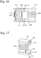
- Fig. 16 is a front view showing this coil device, with a partial cross section for easy understanding of the internal structure.
- Fig. 17 is a perspective view showing a coil member constituting the coil device.
- the coil device comprises two assembled U-shaped magnetic cores 308 (308a, 308b).
- Each magnetic core 308 (308a, 308b) has a straight portion around which a coil is wound, and a bent portion extending in a direction crossing the longitudinal direction of the straight portion from both ends of the straight portion.
- the magnetic cores 308 (308a, 308b) are connected with their end surfaces 310 abutting each other to constitute the rectangularly annular magnetic core.
- Each magnetic core 308 (308a, 308b) is received in each insulation case 301 (301a, 301b), and each coil 309a, 309b is wound around each case to constitute each coil member.
- the insulation case 301 (301a, 301b) has a partially opened hollow portion 311, in which the magnetic core 308 (308a, 308b) is received, with rear and side surfaces of the magnetic core 308 (308a, 308b) covered by the insulation case 301 (301a, 301b).
- One insulation case 301b of the coil member has a projection 307 extending in the abutting direction, and the other insulation case 301a has a recess 306 for receiving the projection.
- the projection 307 comprises a thin-plate-shaped arm having a nail at its tip end, and the recess 306 acts as a fixing hole receiving the arm.
- Each insulation case 301 (301a, 301b) has a spring portion 315 pushing the magnetic core 308 (308a, 308b) toward the abutting surface 310.
- Such structure can provide a coil device with easy coil winding and assembling.
- the magnetic core is not entirely covered with the insulation case, high insulation is necessary between the coil and the magnetic core, when used for high-voltage, high-current reactors, etc.
- an object of the present invention is to provide a coil device constituted by annularly assembling divided magnetic cores, which has improved insulation between coils and magnetic cores, and easiness in handling because the assembled coil members are not easily detached before adhering.
- the present invention provides a coil device comprising a pair of annularly assembled coil members each comprising a coil arranged on a resin case containing a U-shaped magnetic core; each of the coil members having connecting portions on both end sides of the magnetic core; each of the connecting portions having a connecting part and a reinforcing part; the reinforcing part being constituted by a gap between an inner wall of the resin case and an outer wall of the magnetic core, and a projection plate extending in the assembling direction of the coil members, a projection plate of one coil member being insertable into the gap of the other coil member; and the connecting part comprising a hook-shaped projection extending in the assembling direction and a projection receiver, the hook-shaped projection of one coil member being loosely fittable into the projection receiver of the other coil member.
- each coil member preferably has the hook-shaped projection of the connecting part on one side of the magnetic core, and the projection receiver on the other side, when viewed in the assembling direction, and further has a projection plate of the reinforcing part on the side of the projection receiver of the connecting part, and the gap on the side of the hook-shaped projection of the connecting part.
- the positional relation between the hook-shaped projection and projection receiver of the connecting part in one connecting portion of the coil member is 180° inverse to that in the other connecting portion.
- abutting portions of the opposing magnetic cores are preferably surrounded by the projection plates of the reinforcing parts.
- the hook-shaped projection of the connecting part preferably has two arms, each arm having a hook-shaped portion at its tip end.
- the resin case is constituted by two assembled case members, each case member receiving the magnetic core in its bottomed space.
- the resin case preferably has flanges for positioning the coil.
- the present invention provides an easy-to-handle coil device constituted by annularly assembling divided magnetic cores to have improved insulation between coils and magnetic cores, whose coil members are not easily separated even before adhering.
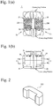
- Fig. 1(a) is a plan view showing an appearance of the coil device
- Fig. 1(b) is its front view
- Fig. 2 is a perspective view showing an example of magnetic cores used in the coil device
- Fig. 3 is a perspective view showing a coil member
- Fig. 4 is a right side view showing the coil member in a direction C
- Fig. 5 is a front view showing it in a direction B.
- a coil is omitted in Figs. 3, 4 and 5 .
- the coil device 1 of the present invention is constituted by assembled coil members 2a, 2b.
- Each coil member 2a, 2b comprises a magnetic core 250, a resin case 3 entirely enclosing the magnetic core, and a coil 200 wound around the resin case 3, the coil members 2a, 2b being assembled with their two connecting portions abutting each other and fixed by an adhesive, to constitute a rectangularly annular coil device 1.
- the coil 200 is wound around a straight portion between flanges 30.
- the straight portion between the flanges 30 has chamfered corners for easy winding of the conductor wire without damage.
- Each end portion of the coil 200 extends through a notch of the flange 30.
- the coil 200 may be constituted by a single conductor wire or a flat, rectangularly cross-sectional conductor wire, which is coated with insulating enamel, or a Litz wire formed by several tens to hundreds of twisted, enameled, thin copper wires to have an increased conductor surface area to reduce temperature elevation by increased resistance due to skin effect. Because the coil member 2a, 2b has a shape making the winding of a coil easy, the type and number of winding of a conductor wire in the coil 200 are not restrictive, but may be selected depending on applications.
- the resin case 3 is constituted by assembling two case members 4a, 4b, and each case member 4a, 4b has a U-shaped, bottomed space partially receiving the magnetic core 250.
- the magnetic core 250 is placed in a space defined by assembled case members 4a, 4b, and the coil members 2a, 2b are assembled with the end surfaces of one magnetic core 250 and the other magnetic core 250 opposing each other.
- the magnetic cores 250 are entirely covered by the resin cases 3 for improved insulation between the coil 200 and the magnetic core 250.
- the magnetic core 250 is preferably a magnetic core of Mn- or Ni- soft ferrite, or a dust magnetic core of crystalline or amorphous alloys such as Fe-Si alloys, Fe-Cr alloys, Fe-Cr-Si alloys, Fe-Al alloys, Fe-Al-Si alloys, Fe-Al-Cr alloys, Fe-Al-Cr-Si alloys, Fe-Ni alloys, Fe-M-B alloys, etc.
- Fe-Si alloys Fe-Cr alloys, Fe-Cr-Si alloys, Fe-Al alloys, Fe-Al-Cr alloys, Fe-Al-Cr-Si alloys, Fe-Ni alloys, Fe-M-B alloys, etc.
- Each coil member 2a, 2b has two connecting portions each comprising a connecting part and a reinforcing part, on both end sides of the U-shaped magnetic core 250.
- Each connecting part is constituted by hook-shaped projections 20a, 20b integral with the resin case 3 and projection receivers 23a, 23b.
- Each reinforcing part is constituted by a gap 26a, 26b defined by an inner surface of the resin case and the magnetic core, and a projection plate 25a, 25b integrally extending from the resin case 3 in the assembling direction of the coil members 2a, 2b.
- Each hook-shaped projection 20a, 20b comprises an arm portion 21 extending in the assembling direction of the coil members 2a, 2b, and a hook-shaped portion at a tip end of the arm portion 21.
- Each projection receiver 23a, 23b is a wall-like portion of the resin case projecting in a direction perpendicular to the assembling direction, which comprises a hollow portion 24a, 24b engageable with a corresponding hook-shaped projection 20a, 20b.
- the hook-shaped projection 20a is loosely fit into the projection receiver 23a
- the hook-shaped projection 20b is loosely fit into the projection receiver 23b.
- the hook-shaped tip portions 22 of the hook-shaped projections 20a, 20b are inserted into the hollow portions 24a, 24b of the projection receivers 23a, 23b, to connect the coil members 2a, 2b.
- each hook-shaped projection 20a, 20b comprises a pair of arms 21 with a space therebetween, and hook-shaped portions 22 connected to their tip ends.
- a pair of arms 21 and a pair of hook-shaped portions 22 are respectively linearly symmetric with respect to a centerline of the space, though they may have different shapes.
- the hook-shaped projections 20a, 20b and the projection receivers 23a, 23b are not restricted to have the depicted shapes as long as they are engageable.
- each projection plate 25a, 25b is a thin plate portion extending from the resin case 3 in the assembling direction of the coil members, slightly receding from an outer surface of the resin case 3.
- Each projection plate 25a, 25b is in a U shape when viewed in the assembling direction, such that it partially surrounds the magnetic core 250. A projection plate of one coil member can be inserted into the gap of the other coil member.
- the projection plate 25a is inserted into the gap 26a, and the projection plate 25b is inserted into the gap 26b, between the opposing coil members.
- abutting portions of the opposing magnetic cores 250 are surrounded by the projection plates 25a, 25b of the reinforcing parts, providing high strength to the connecting portions.
- the movement of the coil members can be limited in the assembling direction. As a result, cooperating with the connecting parts, the disconnection of the coil members 2a, 2b can be prevented during production.
- connection of the coil members 2a, 2b will then be explained.
- the hook-shaped portions 22 of the hook-shaped projections 20a, 20b of the connecting parts are put near the projection receivers 23a, 23b, and then inserted into the hollow portions 24a, 24b of the projection receivers 23a, 23b.
- the insertion elastically flexes the arm portions 21 to reduce their space, so that hook-shaped portions 22 enter the hollow portions 24a, 24b.
- the space between the arm portions 21 expands to the original one, resulting in latching to connect the coil members 2a, 2b. Because the total width of the arm portions 21 including their space is slightly smaller than the width of each hollow portion 24a, 24b, the coil members 2a, 2b can be connected with loose engagement.
- the hook-shaped projections 20a, 20b of the connecting parts are so long as to extend beyond the end surfaces of the projection plates 25a, 25b of the reinforcing parts. Accordingly, to assemble the coil members 1, the projection plates 25a, 25b are inserted into the gaps 26a, 26b of the reinforcing parts, after the hook-shaped portions 22 of the hook-shaped projections 20a, 20b of the connecting parts are inserted into the hollow portions 24a, 24b of the opposing projection receivers 23a, 23b.
- the projection plates are inserted into the gaps of the reinforcing parts formed in the connecting portions, so that the horizontal and vertical, relative positions of the magnetic cores 250 in two core members 2a, 2b can be precisely and easily set to abut the end surfaces of the magnetic cores 250 for assembling, with high precision and little unevenness.
- the hook-shaped projection 20a, 20b and the projection receiver 23a, 23b of each connecting part are positioned, such that the hook-shaped projection 20a, 20b is on one side of the magnetic core 250, while the projection receiver 23a, 23b is on the other side, when viewed in the assembling direction.
- the projection plate 25a of the reinforcing part is on the side of the projection receiver 23a of the connecting part, while the projection plate 25b is on the side of the projection receiver 23b.
- the gap 26a of the reinforcing part is on the side of the hook-shaped projection 20a of the connecting part, while the gap 26b is on the side of the hook-shaped projection 20b.
- the hook-shaped projections 20a, 20b and projection receivers 23a, 23b of the connecting parts of the coil members 2a, 2b are at 180°-inversed positions between one connecting portion and the other connecting portion.
- end portions of the magnetic cores 250 slightly project at the connecting portions of the resin case 3 in the assembled coil members, such that the end surfaces of the magnetic cores 250 can abut each other.
- the projecting width D is preferably 0.5 mm or less.
- the reinforcing parts restrict the moving directions of the coil members, and the loose fitting of the connecting parts enables the use of common resin cases without necessitating different resin cases, even when the uneven sizes of the magnetic cores 250 provide different projecting widths D between the coil members, and even when an insulating spacer such as a resin film, a ceramic or oil paper, etc. is placed between the end surfaces of the magnetic cores 250 to constitute a magnetic gap.
- an annular coil device whose gap may vary from 0 can be easily obtained regardless of a combination of coil members 2a, 2b.
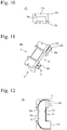
- Figs. 6-15 show the structure of the resin case, Fig. 6 being a perspective view showing one case member (first case member), Fig. 7 being a bottom view showing the first case member in a direction A, Fig. 8 being a right side view showing it in a direction B, Fig. 9 being a left side view showing it in a direction C, Fig. 10 being a front view showing it in a direction D, Fig. 11 being a perspective view showing the other case member (second case member), Fig. 12 being a bottom view showing the second case member in a direction A, Fig. 13 being a right side view showing it in a direction B, Fig. 14 being a left side view showing it in a direction C, and Fig. 15 being a front view showing it in a direction D.
- first case member first case member
- Fig. 7 being a bottom view showing the first case member in a direction A
- Fig. 8 being a right side view showing it in a direction B
- Fig. 9 being
- the resin case is constituted by two case members, a first case member 4a and a second case member 4b.
- Figs. 6-10 show the structure of the first case member.
- the first case member 4a receiving the magnetic core has a basic structure comprising a U-shaped space 13 having a bottom, from which an outer wall 10a and an inner wall 10b integrally extend upward.
- One end portion of the first case member 4a is provided with a projection receiver 23a of the connecting part and a projection plate 25a of the reinforcing part, while the other end portion is provided with a hook-shaped projection 20a and a receded step 14 for constituting the gap 26a of the reinforcing part.
- the outer wall 10a and inner wall 10b are provided with outer steps 11a, 11b for receiving the end portions of the second case member 2b.
- the outer steps 11a, 11b are continuous with the projection plate 25a, and their upper ends are connected at the same height.
- Figs. 11-15 show the structure of the second case member in detail.
- the second case member 4b has a basic structure comprising a U-shaped space 18 having a bottom, from which an outer wall 15a and an inner wall 15b integrally extend downward.
- the second case member 4b is also provided with a connecting part and a reinforcing part at both ends.
- One end portion is provided with a projection receiver 23b of the connecting part and a projection plate 25b of the reinforcing part, while the other end portion is provided with a hook-shaped projection 20b and a receded step 17 for constituting the gap 26b of the reinforcing part.
- Expanded corner portions are provided with four notches supporting end portions of the coil.
- the outer wall 15a and the inner wall 15b are provided with inner steps 16a, 16b.
- the walls are thin on the opening side of the bottomed space 18 and thick on the bottom side, to receive the end portions of the first case member 4a.
- the positioning of the case members is conducted by combining the outer steps 11a, 11b of the first case member 4a with the inner steps 16a, 16b of the second case member 4b. Because the steps of the case members 4a, 4b are fit without gaps, the assembled resin case 3 has substantially no steps on its outer and inner surfaces.
- the resin case is preferably formed by resins having excellent insulation, heat resistance, flexibility and moldability, specifically plastics such as polypunylene sulfide, polyethylene terebuthalate, ABS resins, engineering plastics, etc.
- the present invention can be applied to various coil devices.
Landscapes
- Engineering & Computer Science (AREA)
- Power Engineering (AREA)
- Coils Or Transformers For Communication (AREA)
Applications Claiming Priority (2)
| Application Number | Priority Date | Filing Date | Title |
|---|---|---|---|
| JP2017061681 | 2017-03-27 | ||
| PCT/JP2018/011725 WO2018180998A1 (fr) | 2017-03-27 | 2018-03-23 | Composant de bobine |
Publications (2)
| Publication Number | Publication Date |
|---|---|
| EP3605565A1 true EP3605565A1 (fr) | 2020-02-05 |
| EP3605565A4 EP3605565A4 (fr) | 2020-12-30 |
Family
ID=63675787
Family Applications (1)
| Application Number | Title | Priority Date | Filing Date |
|---|---|---|---|
| EP18775335.5A Withdrawn EP3605565A4 (fr) | 2017-03-27 | 2018-03-23 | Composant de bobine |
Country Status (5)
| Country | Link |
|---|---|
| US (1) | US11515076B2 (fr) |
| EP (1) | EP3605565A4 (fr) |
| JP (1) | JP7020481B2 (fr) |
| CN (1) | CN110476216B (fr) |
| WO (1) | WO2018180998A1 (fr) |
Families Citing this family (2)
| Publication number | Priority date | Publication date | Assignee | Title |
|---|---|---|---|---|
| JPWO2020066631A1 (ja) * | 2018-09-28 | 2021-08-30 | 三菱電機株式会社 | リアクトル |
| US11710595B2 (en) * | 2019-03-10 | 2023-07-25 | Cyntec Co., Ltd. | Magnetic component structure with thermal conductive filler and method of fabricating the same |
Family Cites Families (28)
| Publication number | Priority date | Publication date | Assignee | Title |
|---|---|---|---|---|
| JPS5247056Y2 (fr) | 1973-05-25 | 1977-10-26 | ||
| DE2914447C2 (de) * | 1979-04-10 | 1982-04-22 | Philips Patentverwaltung Gmbh, 2000 Hamburg | Schnittbandkerntransformator mit einem oder mehreren Spulenkörpern |
| US4311978A (en) * | 1979-06-01 | 1982-01-19 | Teccor Electronics, Inc. | U-Core pulse transformer |
| JP2676901B2 (ja) * | 1989-04-14 | 1997-11-17 | 株式会社明電舎 | 三巻線スコット結線変圧器 |
| JPH03117820U (fr) | 1990-03-15 | 1991-12-05 | ||
| DE19814432C1 (de) * | 1998-03-31 | 1999-12-23 | Moeller Gmbh | Elektromagnetisches Schaltgerät mit einem mehrteiligen Gehäuse |
| JP3117820U (ja) | 2005-10-21 | 2006-01-12 | 知司 小林 | マッサージチェアー |
| WO2007108201A1 (fr) * | 2006-03-17 | 2007-09-27 | Tamura Corporation | Element et structure destines a fixer un noyau |
| CN103219135B (zh) * | 2009-03-25 | 2016-01-13 | 住友电气工业株式会社 | 电抗器 |
| DE102009016238B4 (de) * | 2009-04-03 | 2017-09-14 | SUMIDA Components & Modules GmbH | Transformator mit modularem Wicklungsaufbau |
| JP5310460B2 (ja) * | 2009-10-09 | 2013-10-09 | Jfeスチール株式会社 | 積層コアの製造方法 |
| JP5465151B2 (ja) * | 2010-04-23 | 2014-04-09 | 住友電装株式会社 | リアクトル |
| JP5597106B2 (ja) * | 2010-11-19 | 2014-10-01 | 住友電気工業株式会社 | リアクトル |
| JP5120679B1 (ja) * | 2011-05-10 | 2013-01-16 | 住友電気工業株式会社 | リアクトル |
| DE112011105383B4 (de) * | 2011-06-27 | 2022-11-24 | Toyota Jidosha Kabushiki Kaisha | Drossel und Herstellungsverfahren dafür |
| DE112011105382B4 (de) * | 2011-06-27 | 2016-06-30 | Toyota Jidosha Kabushiki Kaisha | Drossel und Herstellungsverfahren dafür |
| JP5951969B2 (ja) * | 2011-11-30 | 2016-07-13 | 株式会社タムラ製作所 | コイル装置 |
| JP6179701B2 (ja) * | 2012-02-24 | 2017-08-16 | 住友電気工業株式会社 | リアクトル、コンバータ、および電力変換装置 |
| JP6005961B2 (ja) * | 2012-03-23 | 2016-10-12 | 株式会社タムラ製作所 | リアクトル及びその製造方法 |
| JP5949137B2 (ja) | 2012-05-18 | 2016-07-06 | トヨタ自動車株式会社 | リアクトル、および、その製造方法 |
| FR2994762B1 (fr) * | 2012-08-23 | 2015-11-20 | Hispano Suiza Sa | Transformateur tournant triphase-diphase a connexion scott |
| WO2015017477A1 (fr) * | 2013-07-31 | 2015-02-05 | US Nano LLC | Appareils et procédés pour synthèse à flux continu de nanofils semi-conducteurs |
| JP5997111B2 (ja) * | 2013-08-04 | 2016-09-28 | 株式会社タムラ製作所 | 樹脂モールドコアとそれを用いたリアクトル |
| JP6315256B2 (ja) * | 2013-12-26 | 2018-04-25 | 住友電装株式会社 | リアクトル |
| HUE044015T2 (hu) * | 2014-01-28 | 2019-09-30 | Soc Es De Electromedicina Y Calidad S A | Nagyfeszültségû, nagyfrekvenciájú, nagyteljesítményû transzformátor |
| CN204390889U (zh) * | 2015-01-30 | 2015-06-10 | 天威云南变压器股份有限公司 | 斯科特平衡变压器 |
| JP6458720B2 (ja) | 2015-12-04 | 2019-01-30 | トヨタ自動車株式会社 | リアクトル |
| JP6747383B2 (ja) * | 2017-06-08 | 2020-08-26 | 株式会社オートネットワーク技術研究所 | リアクトル |
-
2018
- 2018-03-23 EP EP18775335.5A patent/EP3605565A4/fr not_active Withdrawn
- 2018-03-23 WO PCT/JP2018/011725 patent/WO2018180998A1/fr not_active Ceased
- 2018-03-23 CN CN201880022550.XA patent/CN110476216B/zh active Active
- 2018-03-23 JP JP2019509712A patent/JP7020481B2/ja active Active
- 2018-03-23 US US16/496,533 patent/US11515076B2/en active Active
Also Published As
| Publication number | Publication date |
|---|---|
| WO2018180998A1 (fr) | 2018-10-04 |
| US20200381171A1 (en) | 2020-12-03 |
| JPWO2018180998A1 (ja) | 2020-02-13 |
| EP3605565A4 (fr) | 2020-12-30 |
| CN110476216B (zh) | 2022-07-08 |
| JP7020481B2 (ja) | 2022-02-16 |
| CN110476216A (zh) | 2019-11-19 |
| US11515076B2 (en) | 2022-11-29 |
Similar Documents
| Publication | Publication Date | Title |
|---|---|---|
| KR101995737B1 (ko) | 트랜스포머 및 트랜스포머의 제조방법 | |
| US6608544B2 (en) | Reactor | |
| US4603314A (en) | Inductor | |
| US5157368A (en) | Thin type transformer | |
| US20090237196A1 (en) | Method for manufacturing transformer, and transformer | |
| KR20150050025A (ko) | 코일 부품 | |
| KR102359297B1 (ko) | Smps용 변압기 | |
| JP2010219473A (ja) | チョークコイル | |
| US11515076B2 (en) | Coil device | |
| KR101989172B1 (ko) | 플랫 타입 트랜스포머 | |
| JPH06105657B2 (ja) | 変成器 | |
| JP7255153B2 (ja) | リアクトルおよびその製造方法 | |
| US4075590A (en) | Bobbin construction for electrical coils | |
| KR101932232B1 (ko) | 전원공급장치의 트랜스포머용 분리형 보빈 구조 | |
| JP2012164914A (ja) | トランス | |
| KR102143868B1 (ko) | 플랫 타입 트랜스포머 | |
| JPH09115745A (ja) | トランス | |
| KR101779071B1 (ko) | Llc 회로용 트랜스포머 | |
| KR20150045694A (ko) | 코어 및 이를 구비하는 코일 부품 | |
| JP2019169562A (ja) | コイル部品及びトランス | |
| KR200338261Y1 (ko) | 트랜스포머 | |
| JP7338275B2 (ja) | リアクトル用ボビン、リアクトルおよびリアクトルの製造方法 | |
| KR102762547B1 (ko) | 고밀도 및 고효율 트랜스포머 | |
| US20240331934A1 (en) | Coil device | |
| JP7793365B2 (ja) | リアクトル |
Legal Events
| Date | Code | Title | Description |
|---|---|---|---|
| STAA | Information on the status of an ep patent application or granted ep patent |
Free format text: STATUS: THE INTERNATIONAL PUBLICATION HAS BEEN MADE |
|
| PUAI | Public reference made under article 153(3) epc to a published international application that has entered the european phase |
Free format text: ORIGINAL CODE: 0009012 |
|
| STAA | Information on the status of an ep patent application or granted ep patent |
Free format text: STATUS: REQUEST FOR EXAMINATION WAS MADE |
|
| 17P | Request for examination filed |
Effective date: 20191011 |
|
| AK | Designated contracting states |
Kind code of ref document: A1 Designated state(s): AL AT BE BG CH CY CZ DE DK EE ES FI FR GB GR HR HU IE IS IT LI LT LU LV MC MK MT NL NO PL PT RO RS SE SI SK SM TR |
|
| AX | Request for extension of the european patent |
Extension state: BA ME |
|
| DAV | Request for validation of the european patent (deleted) | ||
| DAX | Request for extension of the european patent (deleted) | ||
| A4 | Supplementary search report drawn up and despatched |
Effective date: 20201202 |
|
| RIC1 | Information provided on ipc code assigned before grant |
Ipc: H01F 27/26 20060101ALI20201126BHEP Ipc: H01F 27/32 20060101ALI20201126BHEP Ipc: H01F 27/24 20060101AFI20201126BHEP Ipc: H01F 37/00 20060101ALI20201126BHEP Ipc: H01F 30/10 20060101ALI20201126BHEP |
|
| GRAP | Despatch of communication of intention to grant a patent |
Free format text: ORIGINAL CODE: EPIDOSNIGR1 |
|
| STAA | Information on the status of an ep patent application or granted ep patent |
Free format text: STATUS: GRANT OF PATENT IS INTENDED |
|
| INTG | Intention to grant announced |
Effective date: 20210512 |
|
| STAA | Information on the status of an ep patent application or granted ep patent |
Free format text: STATUS: THE APPLICATION IS DEEMED TO BE WITHDRAWN |
|
| 18D | Application deemed to be withdrawn |
Effective date: 20210923 |