EP3605809A1 - Entraînement de moyeu de roue électrique à dissipation de chaleur améliorée - Google Patents
Entraînement de moyeu de roue électrique à dissipation de chaleur améliorée Download PDFInfo
- Publication number
- EP3605809A1 EP3605809A1 EP18187321.7A EP18187321A EP3605809A1 EP 3605809 A1 EP3605809 A1 EP 3605809A1 EP 18187321 A EP18187321 A EP 18187321A EP 3605809 A1 EP3605809 A1 EP 3605809A1
- Authority
- EP
- European Patent Office
- Prior art keywords
- wheel hub
- hub drive
- electric
- windings
- drive
- Prior art date
- Legal status (The legal status is an assumption and is not a legal conclusion. Google has not performed a legal analysis and makes no representation as to the accuracy of the status listed.)
- Withdrawn
Links
Images



Classifications
-
- H—ELECTRICITY
- H02—GENERATION; CONVERSION OR DISTRIBUTION OF ELECTRIC POWER
- H02K—DYNAMO-ELECTRIC MACHINES
- H02K21/00—Synchronous motors having permanent magnets; Synchronous generators having permanent magnets
- H02K21/26—Synchronous motors having permanent magnets; Synchronous generators having permanent magnets with rotating armatures and stationary magnets
-
- B—PERFORMING OPERATIONS; TRANSPORTING
- B60—VEHICLES IN GENERAL
- B60L—PROPULSION OF ELECTRICALLY-PROPELLED VEHICLES; SUPPLYING ELECTRIC POWER FOR AUXILIARY EQUIPMENT OF ELECTRICALLY-PROPELLED VEHICLES; ELECTRODYNAMIC BRAKE SYSTEMS FOR VEHICLES IN GENERAL; MAGNETIC SUSPENSION OR LEVITATION FOR VEHICLES; MONITORING OPERATING VARIABLES OF ELECTRICALLY-PROPELLED VEHICLES; ELECTRIC SAFETY DEVICES FOR ELECTRICALLY-PROPELLED VEHICLES
- B60L50/00—Electric propulsion with power supplied within the vehicle
- B60L50/20—Electric propulsion with power supplied within the vehicle using propulsion power generated by humans or animals
-
- H—ELECTRICITY
- H02—GENERATION; CONVERSION OR DISTRIBUTION OF ELECTRIC POWER
- H02K—DYNAMO-ELECTRIC MACHINES
- H02K7/00—Arrangements for handling mechanical energy structurally associated with dynamo-electric machines, e.g. structural association with mechanical driving motors or auxiliary dynamo-electric machines
- H02K7/18—Structural association of electric generators with mechanical driving motors, e.g. with turbines
- H02K7/1807—Rotary generators
- H02K7/1846—Rotary generators structurally associated with wheels or associated parts
-
- H—ELECTRICITY
- H02—GENERATION; CONVERSION OR DISTRIBUTION OF ELECTRIC POWER
- H02K—DYNAMO-ELECTRIC MACHINES
- H02K3/00—Details of windings
- H02K3/32—Windings characterised by the shape, form or construction of the insulation
- H02K3/38—Windings characterised by the shape, form or construction of the insulation around winding heads, equalising connectors, or connections thereto
-
- H—ELECTRICITY
- H02—GENERATION; CONVERSION OR DISTRIBUTION OF ELECTRIC POWER
- H02K—DYNAMO-ELECTRIC MACHINES
- H02K7/00—Arrangements for handling mechanical energy structurally associated with dynamo-electric machines, e.g. structural association with mechanical driving motors or auxiliary dynamo-electric machines
- H02K7/10—Structural association with clutches, brakes, gears, pulleys or mechanical starters
- H02K7/116—Structural association with clutches, brakes, gears, pulleys or mechanical starters with gears
-
- Y—GENERAL TAGGING OF NEW TECHNOLOGICAL DEVELOPMENTS; GENERAL TAGGING OF CROSS-SECTIONAL TECHNOLOGIES SPANNING OVER SEVERAL SECTIONS OF THE IPC; TECHNICAL SUBJECTS COVERED BY FORMER USPC CROSS-REFERENCE ART COLLECTIONS [XRACs] AND DIGESTS
- Y02—TECHNOLOGIES OR APPLICATIONS FOR MITIGATION OR ADAPTATION AGAINST CLIMATE CHANGE
- Y02T—CLIMATE CHANGE MITIGATION TECHNOLOGIES RELATED TO TRANSPORTATION
- Y02T10/00—Road transport of goods or passengers
- Y02T10/60—Other road transportation technologies with climate change mitigation effect
- Y02T10/64—Electric machine technologies in electromobility
Definitions
- the present invention relates to an electric wheel hub drive according to the preamble of independent claim 1.
- a wheel hub drive for a vehicle consists of a frame-fixed axle and a hub housing rotatably mounted about the axle, to which the driven rim is fastened with tires of the vehicle via several spokes.
- a gear can be provided to operate the electric motor at a better operating point. For reasons of noise and costs, however, a transmission is often dispensed with.
- Wheel hub drives with different electric motors are known from the prior art. Permanently excited synchronous machines or electronically commutated electric motors are often used. In such electric motors, the stator has a stator winding, the rotor not being wound but equipped with one or more permanent magnets. Heat losses therefore mainly occur on the stator side.
- the stator is rotatably connected to the axle or fastened to the axle, the rotor being rotatably mounted with respect to the axle and generally being directly connected to the hub housing. Due to the small cross-sectional area of the axis, only little heat can be dissipated to the environment via the axis.
- the waste heat generated in the stator must therefore predominantly be transferred to the hub housing via the air gap between the stator and rotor and finally dissipated to the environment.
- the air gap represents a significant thermal resistance, which is why the thermally limited continuous power of the electric motor is reduced.
- the performance of wheel hub drives with a permanently excited synchronous machine is therefore limited for thermal reasons.
- the object of the present invention is to provide an electric wheel hub drive with an advantageous structure and improved heat dissipation.
- independent claim 1 the object is achieved by the features of independent claim 1. Accordingly, in the case of a wheel hub drive according to the preamble of independent claim 1, there is an inventive solution to the problem if there is a direct thermal contact between windings, iron back yoke and hub housing and the windings with iron back iron the axis are rotatably mounted.
- the electric motor is arranged inside the hub shell.
- the permanent magnets are advantageously arranged on the inside and are surrounded radially by windings with iron sheet back yoke. Due to the external arrangement of the windings, which are the main source of thermal losses, the waste heat generated in the windings no longer has to be dissipated to the outside via the air gap between the windings and the magnet.
- a winding can be defined by several turns consisting of an electrical conductor.
- a winding system can consist of several windings. The winding system is non-rotatably connected to the iron plate yoke and the hub shell. This minimizes the thermal resistance, which leads to particularly good heat dissipation. If possible, materials with a high thermal conductivity should be used for the hub shell.
- the magnetic iron sheet yoke preferably consists of an iron sheet package, the hub shell can be made of aluminum, for example.
- the electric motor is a grooved motor, particularly preferably the grooved motor has a single tooth winding.
- the iron plate yoke conducts the magnetic flux better than the surrounding air. The magnetic flux is thus conducted through the iron sheet yoke. Teeth in the iron sheet back yoke which are wrapped in windings guide the magnetic flux close to the permanent magnets. This means that a small effective air gap between the iron sheet yoke and the magnet can be realized. This leads to high attraction and repulsion forces between the permanent magnets and the teeth and thus to a high torque of the motor.
- the wheel hub drive has a control, the windings having two or more phases.
- the controller can be mechanically connected to the axle of the wheel hub drive, the wheel hub drive being set up in such a way that an electric current is transmitted from the axle to the rotatably mounted windings for each of the phases.
- the controller can be connected to the axis either directly or indirectly.
- the control in this embodiment is designed to be non-rotatable with the axis.
- the control can be integrated in the hub housing.
- the controller can be mechanically connected to the hub housing, the wheel hub drive being set up in such a way that the controller is supplied with direct current, with a BUS or communication signal, for example for controlling the electric motor or for transmitting the support level to the Control is transferred.
- the control is thus directly or indirectly non-rotatably connected to the windings or the iron sheet yoke or the hub shell.
- the direct current can be transmitted by means of a sliding contact or also inductively.
- the communication signal is preferably transmitted inductively, also capacitive coupling or radio technology, e.g. according to the Bluetooth standard, is conceivable as a transmission method.
- this variant allows the power electronics to be mounted on the rotating hub housing with the power transistors in direct contact with the hub housing, which allows good heat dissipation of the control losses to the outside.
- the wheel hub drive has at least two sliding contacts for transmitting electrical energy to the rotatably mounted windings.
- a brush contact can also preferably be provided as the sliding contact.
- At least two sliding contacts are required to transfer the at least two poles of an electrical circuit.
- the wheel hub drive can have at least one inductive coupling for transmitting electrical energy to the rotatably mounted windings.
- the wheel hub drive according to the invention thus has no wear parts that would require complex maintenance of the wheel hub drive.
- the electric wheel hub drive is well protected against dirt and there is less risk of electrical short circuits or interruptions due to contamination or moisture.
- the wheel hub drive has a motor freewheel.
- iron losses occur in all soft magnetic components. These are mainly dependent on the speed of rotation and also occur when driving with the engine switched off, if no engine freewheel is installed.
- the motor can be decoupled by a freewheel. This is the case, for example, when the batteries are empty and rotating the motor would only require additional energy from the driver due to the iron losses.
- the engine be decoupled if the bike is braked by the engine on a slight slope or the engine is switched off for legal or other reasons.
- the wheel hub drive is designed as a direct drive.
- a direct drive could save the weight and cost of a transmission.
- a direct drive also produces less noise.
- the wheel hub drive has a transmission.
- the motor can be operated at a higher speed, which can result in an optimal working range or a higher torque.
- the wheel hub drive has a single-stage or multi-stage planetary gear, the sun gear of the first stage is connected to the magnet system in a rotationally fixed manner and the ring gear of the last stage is connected to the hub housing in a rotationally fixed manner or via a freewheel and drives the hub housing.
- a planetary gear has a compact design and can be easily integrated into the wheel hub drive.
- a planet carrier can be firmly connected to the axis.
- the freewheel can be switched on or off depending on the speed of the bicycle or the speed of the motor.
- the vehicle is a two-wheeler, particularly preferably a bicycle with a support motor.
- bicycles are also called pedelecs or e-bikes.
- Figure 1 shows a longitudinal section through a wheel hub drive 1 according to the invention according to a first embodiment.
- the wheel hub drive 1 has a fixed axle 2, which can be fixed, for example, to a bicycle frame (not shown further).
- the wheel hub drive 1 also has a hub housing 3 rotatably mounted about the axis 2 and an electric motor designed as a permanently excited synchronous machine for driving the hub housing 3.
- the hub housing 3 is rotatably supported with respect to the axis 2 via at least two bearings, of which only the left bearing is provided with the reference number 16 in the drawing.
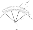
- the electric motor has external windings 5 and a magnet system 6 radially enclosed by the windings 5.
- the windings are usually arranged in a rotationally fixed manner and are therefore referred to as a stator.
- the magnet system or the permanent magnets move in relation to the non-rotatable stator and are therefore usually referred to as a rotor.
- the iron sheet yoke 4 can have a plurality of teeth 17 arranged uniformly distributed over the circumference, each of which is wound with a coil 5.
- the coils 5 are connected to form a three-phase winding 5.
- a plurality of permanent magnets 7 arranged over the circumference are arranged on the outer circumference of the magnet system 6. Between windings 5 and magnet system 6 there is one in both Figures 1 and 2 shown air gap 8.
- the magnet system 6 is rotatably connected to the axis 2.
- the winding 5, however, is rotatably mounted with respect to the axis 2 and is directly connected to the hub housing 3.
- the outer circumference of the iron yoke 4 is in full contact with the inside of the hub shell 3, so that an optimal transfer of the waste heat generated in the windings 5 via the hub shell 3 to the surroundings is ensured.
- a controller in the form of a hub housing-side controller 9 is provided.
- the controller 9 can be arranged on a control board.
- the control board is supplied with direct current via a current transmission unit 10.
- the current transmission unit 10 can be designed, for example, as a sliding contact between the fixed axis 2 and the rotatably mounted assembly.
- a conventional brush contact is particularly suitable for transmitting the direct current.
- an additional BUS or communication signal must be transmitted to the controller 9, for example to control the electronic commutation of the electric motor or to transmit the support level.
- the BUS signal can be transmitted by means of radio technology and preferably via a Bluetooth connection.
- the three phases of the windings are energized by the controller 9 via the phase connections 11, 12 and 13, which are only shown schematically.
- FIG. 3 shows a longitudinal section through a wheel hub drive according to the invention according to a second embodiment.
- the basic structure corresponds to the structure according to the exemplary embodiment from FIGS Figures 1 and 2 , The difference is that the controller 9 in the exemplary embodiment according to FIG Figure 3 is connected to the fixed assembly.
- the control board 9 is axially fixed.
- a current must be applied to the rotatably mounted one Module are transferred.
- a total of three power transmission units 10 are provided between the fixed axis 2 and the rotating hub housing 3.
- the transmission can take place by means of sliding contact or inductive coupling.
- Figure 4 shows a longitudinal section through a wheel hub drive 1 according to the invention according to a further embodiment.
- the control 9 can be arranged on the hub housing 3 and thus on the rotating part of the wheel.
- the current commutation for the electric motor can take place in the controller 9.
- the current can thus be transmitted from the rotationally fixed to the rotating part via only two current transmission units 10.
- the embodiment in the Figure 4 shows a direct drive.
- a motor freewheel 17 can be installed between magnet system 6 and axis 2.
- the motor freewheel 17 can decouple the motor from the rotationally fixed axis 2.
- the motor freewheel 17 can prevent the magnet system 6 from turning backwards when the motor is active.
- the magnet system 6 In a first state, the magnet system 6 is rotatably connected to the axis 2.
- the motor can drive the vehicle by supplying electrical energy.
- the motor freewheel 17 can be active, so that the magnet system 6 also rotates with the windings 5.
- the magnet system 6 rotates with the hub housing 3, so the relative speed between the windings 5 and the magnet system 6 is zero and there are no iron losses.
- the vehicle is braked less because, for example, no iron losses of the engine have to be overcome, which increases driving comfort, among other things.
- FIG. 5 shows a longitudinal section through a wheel hub drive according to the invention according to a further embodiment with a gear 21.
- the gear 21 may be a single or multi-stage planetary gear.
- the sun gear 20 can be connected in a rotationally fixed manner to the magnet system 6 and thus to the permanent magnet 7.
- the magnet system 6 is rotatably supported with respect to the axis 2 by magnet system bearings 22.
- magnet system bearings 22 In the exemplary embodiment, two magnetic system bearings 22 are shown.
- the sun gear 20 is in engagement with the planet gear 23.
- a ring gear 18 is engaged on the planet gear 23.
- the ring gear 18 can be non-rotatably connected to the hub shell 3.
- the electric motor can be operated at a higher speed while the vehicle is being moved with a normal speed bicycle.
- the transmission 21 can generate a higher torque on the wheel of the vehicle, as a result of which, for example, steeper increases can be overcome.
- a freewheel could additionally be placed between planet carrier 19 and axis 2.
- the entire gear 21 and the magnet system 6 with the windings 5 and the hub housing 3 also rotate when the freewheel is active, so that no iron losses in the iron yoke 4 or friction losses in the gear 21 occur.
- Figure 6 shows a longitudinal section through a wheel hub drive according to the invention according to a further embodiment with a gear 21 and a motor freewheel 17 and a clutch 24.
- the combination of the gear 21 with one or more freewheels and / or one or more clutches makes it possible to implement a manual transmission.
- the freewheels represent a special clutch form, with power transmission taking place in one direction of rotation, while no power transmission taking place in the other direction of rotation.
- the power transmission can be made dependent on factors other than the direction of rotation.
- a controller can give a signal to the clutch, for example, when the signal is active there is a power transmission and when the signal is inactive there is no power transmission via the clutch or vice versa.
- the embodiment shown in the figure shows a single-stage planetary gear, a motor freewheel 17 being arranged between the ring gear 18 and the hub housing 3.
- a clutch 24 is arranged between magnet system 6 and axis 2. This arrangement results in three sensible operating states.
- the engine In a first operating state, the engine is active and the clutch 24 is open (there is no power transmission).
- the transmission 21 is active and the electric wheel hub drive 1 delivers a high torque to the wheel of the vehicle.
- a second operating state the engine is active and the clutch 24 is closed.
- the drive behaves like a direct drive without a gear.
- the gear 21 is switched off via the freewheel and the gear 21 therefore generates neither friction losses nor noise.
- a smaller torque is generated on the wheel of the vehicle, but a higher speed of rotation of the wheel and thus a higher speed for the vehicle is possible.
- the engine In a third operating state, the engine is deactivated and the clutch is open.
- the magnet system 6 rotates with the iron sheet yoke 4, there are no iron losses.
- the gear 21 rotates slowly backwards and generates low friction losses, which can be prevented by a further freewheel between the sun gear 20 and the magnet system 6.
- the magnet system stops and there are iron losses but no friction losses. In any case, the state with the lowest losses occurs; intermediate states are also possible.
- the electric motor as a generator and to recuperate energy.
- mechanical energy can be converted into electrical energy, for example when driving downhill or braking.
- the electrical energy can, for example, be stored in the battery or the rechargeable battery.
Landscapes
- Engineering & Computer Science (AREA)
- Power Engineering (AREA)
- Transportation (AREA)
- Mechanical Engineering (AREA)
- Arrangement Or Mounting Of Propulsion Units For Vehicles (AREA)
Priority Applications (3)
| Application Number | Priority Date | Filing Date | Title |
|---|---|---|---|
| EP18187321.7A EP3605809A1 (fr) | 2018-08-03 | 2018-08-03 | Entraînement de moyeu de roue électrique à dissipation de chaleur améliorée |
| DE212019000276.5U DE212019000276U1 (de) | 2018-08-03 | 2019-07-30 | Elektrischer Radnabenantrieb mit verbesserter Wärmeabfuhr |
| PCT/EP2019/070506 WO2020025613A1 (fr) | 2018-08-03 | 2019-07-30 | Entraînement de moyeu de roue présentant une dissipation thermique améliorée |
Applications Claiming Priority (1)
| Application Number | Priority Date | Filing Date | Title |
|---|---|---|---|
| EP18187321.7A EP3605809A1 (fr) | 2018-08-03 | 2018-08-03 | Entraînement de moyeu de roue électrique à dissipation de chaleur améliorée |
Publications (1)
| Publication Number | Publication Date |
|---|---|
| EP3605809A1 true EP3605809A1 (fr) | 2020-02-05 |
Family
ID=63144916
Family Applications (1)
| Application Number | Title | Priority Date | Filing Date |
|---|---|---|---|
| EP18187321.7A Withdrawn EP3605809A1 (fr) | 2018-08-03 | 2018-08-03 | Entraînement de moyeu de roue électrique à dissipation de chaleur améliorée |
Country Status (3)
| Country | Link |
|---|---|
| EP (1) | EP3605809A1 (fr) |
| DE (1) | DE212019000276U1 (fr) |
| WO (1) | WO2020025613A1 (fr) |
Cited By (1)
| Publication number | Priority date | Publication date | Assignee | Title |
|---|---|---|---|---|
| DE102023210396B3 (de) * | 2023-10-23 | 2024-12-24 | Zf Friedrichshafen Ag | Nabenantrieb für ein Fahrzeug |
Families Citing this family (1)
| Publication number | Priority date | Publication date | Assignee | Title |
|---|---|---|---|---|
| DE102022212724A1 (de) * | 2022-11-28 | 2024-05-29 | M. L. DriveSolutions GmbH | Antrieb für ein leichtes Elektrofahrzeug und ein leichtes Elektrofahrzeug |
Citations (5)
| Publication number | Priority date | Publication date | Assignee | Title |
|---|---|---|---|---|
| EP0695662A1 (fr) * | 1994-08-04 | 1996-02-07 | Chen-Chi Yang | Dispositif d'actionnement pour roue à moteur et procédé de fabrication correspondant |
| US5600191A (en) * | 1994-12-19 | 1997-02-04 | Yang; Chen-Chi | Driving assembly for motor wheels |
| WO2010077300A2 (fr) * | 2008-12-15 | 2010-07-08 | I2C Catalyst Partners | Bicyclette électrique |
| DE102012018888A1 (de) * | 2012-09-26 | 2014-03-27 | Sew-Eurodrive Gmbh & Co Kg | Elektromotor |
| DE102012110055A1 (de) * | 2012-10-22 | 2014-06-12 | Frederick Adler | Freilaufnabe |
Family Cites Families (2)
| Publication number | Priority date | Publication date | Assignee | Title |
|---|---|---|---|---|
| EP1729397B1 (fr) * | 2004-03-25 | 2017-01-11 | Mitsubishi Denki Kabushiki Kaisha | Machine électrique rotative |
| JP4637959B2 (ja) * | 2009-06-24 | 2011-02-23 | パナソニック株式会社 | 電動機のステータおよび電動機および電動自転車 |
-
2018
- 2018-08-03 EP EP18187321.7A patent/EP3605809A1/fr not_active Withdrawn
-
2019
- 2019-07-30 WO PCT/EP2019/070506 patent/WO2020025613A1/fr not_active Ceased
- 2019-07-30 DE DE212019000276.5U patent/DE212019000276U1/de active Active
Patent Citations (5)
| Publication number | Priority date | Publication date | Assignee | Title |
|---|---|---|---|---|
| EP0695662A1 (fr) * | 1994-08-04 | 1996-02-07 | Chen-Chi Yang | Dispositif d'actionnement pour roue à moteur et procédé de fabrication correspondant |
| US5600191A (en) * | 1994-12-19 | 1997-02-04 | Yang; Chen-Chi | Driving assembly for motor wheels |
| WO2010077300A2 (fr) * | 2008-12-15 | 2010-07-08 | I2C Catalyst Partners | Bicyclette électrique |
| DE102012018888A1 (de) * | 2012-09-26 | 2014-03-27 | Sew-Eurodrive Gmbh & Co Kg | Elektromotor |
| DE102012110055A1 (de) * | 2012-10-22 | 2014-06-12 | Frederick Adler | Freilaufnabe |
Cited By (1)
| Publication number | Priority date | Publication date | Assignee | Title |
|---|---|---|---|---|
| DE102023210396B3 (de) * | 2023-10-23 | 2024-12-24 | Zf Friedrichshafen Ag | Nabenantrieb für ein Fahrzeug |
Also Published As
| Publication number | Publication date |
|---|---|
| DE212019000276U1 (de) | 2020-12-18 |
| WO2020025613A1 (fr) | 2020-02-06 |
Similar Documents
| Publication | Publication Date | Title |
|---|---|---|
| EP2562072B1 (fr) | Entraînement de roue électrique pour un véhicule, notamment un vélo | |
| DE112009005302B4 (de) | Rotierende elektrische Maschinenvorrichtung | |
| DE60127462T2 (de) | Federbein, versehen mit Antriebsmitteln | |
| DE69116160T2 (de) | Ein elektrischer leistungsantrieb für fahrzeuge | |
| EP2668053B1 (fr) | Système convertisseur électromécanique pour véhicules électriques | |
| DE69515393T2 (de) | Motor mit Reduktionsgetriebe | |
| DE102009060199A1 (de) | Elektrische Rotationsmaschine mit variablem Magnetfluss | |
| DE112008002978T5 (de) | Elektromotor und Antriebsvorrichtung | |
| WO2012019690A2 (fr) | Unité d'entraînement pour une roue de véhicule, roue de véhicule et procédé pour entraîner une roue de véhicule | |
| EP1685642A1 (fr) | Transmission magnetodynamique a reglage continu | |
| DE3908234A1 (de) | Zusatzbremseinrichtung fuer fahrzeuge | |
| WO1991001897A1 (fr) | Commande, notamment pour fauteuils roulants | |
| DE102012004287A1 (de) | Elektromotor | |
| DE102011084092A1 (de) | Elektrische Maschine, insbesondere Antriebsmaschine für Fahrzeuge | |
| EP3605809A1 (fr) | Entraînement de moyeu de roue électrique à dissipation de chaleur améliorée | |
| DE10053265C2 (de) | Feststellbremseinrichtung an Fahrzeugen und Antriebssystem mit einer Feststellbremseinrichtung | |
| DE202018103172U1 (de) | Motoranordnung | |
| DE102007045413A1 (de) | Trommelantrieb | |
| EP0914272B1 (fr) | Systeme convertisseur d'energie arrange a ou dans un moyeu de roue | |
| EP2331447B1 (fr) | Système d'entraînement de chariot élévateur | |
| DE102020105915A1 (de) | Axialflussmotor sowie fahrerloses Transportfahrzeug | |
| DE102021112693A1 (de) | Antriebsmodul mit Scheibenläufermotor für ein elektrisch betriebenes Fahrzeug sowie Antriebsanordnung mit dem Antriebsmodul | |
| DE102009036890A1 (de) | Antriebseinheit für ein Fahrrad mit elektromotorischem Antrieb | |
| DE102013219309A1 (de) | Baukastensystem und Verfahren zur Herstellung einer Elektromaschine | |
| DE102007033838A1 (de) | Außenläufer-Elektromotor, Kraftfahrzeug mit Außenläufer-Elektromotor und Verfahren zum Betreiben eines solchen Fahrzeugs |
Legal Events
| Date | Code | Title | Description |
|---|---|---|---|
| PUAI | Public reference made under article 153(3) epc to a published international application that has entered the european phase |
Free format text: ORIGINAL CODE: 0009012 |
|
| AK | Designated contracting states |
Kind code of ref document: A1 Designated state(s): AL AT BE BG CH CY CZ DE DK EE ES FI FR GB GR HR HU IE IS IT LI LT LU LV MC MK MT NL NO PL PT RO RS SE SI SK SM TR |
|
| AX | Request for extension of the european patent |
Extension state: BA ME |
|
| RAP1 | Party data changed (applicant data changed or rights of an application transferred) |
Owner name: MAXON INTERNATIONAL AG |
|
| STAA | Information on the status of an ep patent application or granted ep patent |
Free format text: STATUS: THE APPLICATION IS DEEMED TO BE WITHDRAWN |
|
| 18D | Application deemed to be withdrawn |
Effective date: 20200806 |