EP3605834B1 - Dispositif de direction assistée électrique - Google Patents
Dispositif de direction assistée électrique Download PDFInfo
- Publication number
- EP3605834B1 EP3605834B1 EP17903924.3A EP17903924A EP3605834B1 EP 3605834 B1 EP3605834 B1 EP 3605834B1 EP 17903924 A EP17903924 A EP 17903924A EP 3605834 B1 EP3605834 B1 EP 3605834B1
- Authority
- EP
- European Patent Office
- Prior art keywords
- current
- control
- phase
- abnormality
- armature winding
- Prior art date
- Legal status (The legal status is an assumption and is not a legal conclusion. Google has not performed a legal analysis and makes no representation as to the accuracy of the status listed.)
- Active
Links
Images


Classifications
-
- H—ELECTRICITY
- H02—GENERATION; CONVERSION OR DISTRIBUTION OF ELECTRIC POWER
- H02P—CONTROL OR REGULATION OF ELECTRIC MOTORS, ELECTRIC GENERATORS OR DYNAMO-ELECTRIC CONVERTERS; CONTROLLING TRANSFORMERS, REACTORS OR CHOKE COILS
- H02P29/00—Arrangements for regulating or controlling electric motors, appropriate for both AC and DC motors
- H02P29/02—Providing protection against overload without automatic interruption of supply
- H02P29/024—Detecting a fault condition, e.g. short circuit, locked rotor, open circuit or loss of load
- H02P29/028—Detecting a fault condition, e.g. short circuit, locked rotor, open circuit or loss of load the motor continuing operation despite the fault condition, e.g. eliminating, compensating for or remedying the fault
-
- B—PERFORMING OPERATIONS; TRANSPORTING
- B62—LAND VEHICLES FOR TRAVELLING OTHERWISE THAN ON RAILS
- B62D—MOTOR VEHICLES; TRAILERS
- B62D5/00—Power-assisted or power-driven steering
- B62D5/04—Power-assisted or power-driven steering electrical, e.g. using an electric servo-motor connected to, or forming part of, the steering gear
- B62D5/0457—Power-assisted or power-driven steering electrical, e.g. using an electric servo-motor connected to, or forming part of, the steering gear characterised by control features of the drive means as such
- B62D5/046—Controlling the motor
- B62D5/0463—Controlling the motor calculating assisting torque from the motor based on driver input
-
- B—PERFORMING OPERATIONS; TRANSPORTING
- B62—LAND VEHICLES FOR TRAVELLING OTHERWISE THAN ON RAILS
- B62D—MOTOR VEHICLES; TRAILERS
- B62D5/00—Power-assisted or power-driven steering
- B62D5/04—Power-assisted or power-driven steering electrical, e.g. using an electric servo-motor connected to, or forming part of, the steering gear
- B62D5/0457—Power-assisted or power-driven steering electrical, e.g. using an electric servo-motor connected to, or forming part of, the steering gear characterised by control features of the drive means as such
- B62D5/0481—Power-assisted or power-driven steering electrical, e.g. using an electric servo-motor connected to, or forming part of, the steering gear characterised by control features of the drive means as such monitoring the steering system, e.g. failures
-
- B—PERFORMING OPERATIONS; TRANSPORTING
- B62—LAND VEHICLES FOR TRAVELLING OTHERWISE THAN ON RAILS
- B62D—MOTOR VEHICLES; TRAILERS
- B62D5/00—Power-assisted or power-driven steering
- B62D5/04—Power-assisted or power-driven steering electrical, e.g. using an electric servo-motor connected to, or forming part of, the steering gear
- B62D5/0457—Power-assisted or power-driven steering electrical, e.g. using an electric servo-motor connected to, or forming part of, the steering gear characterised by control features of the drive means as such
- B62D5/0481—Power-assisted or power-driven steering electrical, e.g. using an electric servo-motor connected to, or forming part of, the steering gear characterised by control features of the drive means as such monitoring the steering system, e.g. failures
- B62D5/0484—Power-assisted or power-driven steering electrical, e.g. using an electric servo-motor connected to, or forming part of, the steering gear characterised by control features of the drive means as such monitoring the steering system, e.g. failures for reaction to failures, e.g. limp home
-
- B—PERFORMING OPERATIONS; TRANSPORTING
- B62—LAND VEHICLES FOR TRAVELLING OTHERWISE THAN ON RAILS
- B62D—MOTOR VEHICLES; TRAILERS
- B62D5/00—Power-assisted or power-driven steering
- B62D5/04—Power-assisted or power-driven steering electrical, e.g. using an electric servo-motor connected to, or forming part of, the steering gear
- B62D5/0457—Power-assisted or power-driven steering electrical, e.g. using an electric servo-motor connected to, or forming part of, the steering gear characterised by control features of the drive means as such
- B62D5/0481—Power-assisted or power-driven steering electrical, e.g. using an electric servo-motor connected to, or forming part of, the steering gear characterised by control features of the drive means as such monitoring the steering system, e.g. failures
- B62D5/0493—Power-assisted or power-driven steering electrical, e.g. using an electric servo-motor connected to, or forming part of, the steering gear characterised by control features of the drive means as such monitoring the steering system, e.g. failures detecting processor errors, e.g. plausibility of steering direction
-
- H—ELECTRICITY
- H02—GENERATION; CONVERSION OR DISTRIBUTION OF ELECTRIC POWER
- H02P—CONTROL OR REGULATION OF ELECTRIC MOTORS, ELECTRIC GENERATORS OR DYNAMO-ELECTRIC CONVERTERS; CONTROLLING TRANSFORMERS, REACTORS OR CHOKE COILS
- H02P27/00—Arrangements or methods for the control of AC motors characterised by the kind of supply voltage
- H02P27/04—Arrangements or methods for the control of AC motors characterised by the kind of supply voltage using variable-frequency supply voltage, e.g. inverter or converter supply voltage
- H02P27/06—Arrangements or methods for the control of AC motors characterised by the kind of supply voltage using variable-frequency supply voltage, e.g. inverter or converter supply voltage using DC to AC converters or inverters
-
- H—ELECTRICITY
- H02—GENERATION; CONVERSION OR DISTRIBUTION OF ELECTRIC POWER
- H02P—CONTROL OR REGULATION OF ELECTRIC MOTORS, ELECTRIC GENERATORS OR DYNAMO-ELECTRIC CONVERTERS; CONTROLLING TRANSFORMERS, REACTORS OR CHOKE COILS
- H02P27/00—Arrangements or methods for the control of AC motors characterised by the kind of supply voltage
- H02P27/04—Arrangements or methods for the control of AC motors characterised by the kind of supply voltage using variable-frequency supply voltage, e.g. inverter or converter supply voltage
- H02P27/06—Arrangements or methods for the control of AC motors characterised by the kind of supply voltage using variable-frequency supply voltage, e.g. inverter or converter supply voltage using DC to AC converters or inverters
- H02P27/08—Arrangements or methods for the control of AC motors characterised by the kind of supply voltage using variable-frequency supply voltage, e.g. inverter or converter supply voltage using DC to AC converters or inverters with pulse width modulation
Definitions
- the present invention relates to an electric power steering apparatus in which an electric motor produces assist torque for assisting steering torque produced by a vehicle driver and more particularly to an electric power steering apparatus in which a control unit for controlling the motor has a fail-safe function.
- an electric power steering apparatus in which an electric motor produces assist torque for assisting steering torque produced by a vehicle driver is configured in such a way as to control the electric motor based on signals from various kinds of sensors.
- the conventional electric power steering apparatus disclosed in Patent Document 1 utilizes other values excluding the abnormal value and performs backup control that is different from the backup control at a time when no abnormality exists so as to continue the control of the electric motor; in addition, when two or more kinds of detection values are abnormal, the conventional electric power steering apparatus stops the control of the electric motor or tries to perform additional backup control.
- Patent Document 1 makes it possible that even when due to a failure in a sensor, an abnormality occurs in a detection value, driving of the electric motor is continued without utilizing the abnormal detection value so that the steering assist can be continued, and makes it possible that the driver can appropriately be aware of the occurrence of the failure, there can be prevented the situation that while the driver continues to utilize the apparatus without being aware of the failure in the apparatus, another member also fails and hence the driving of the electric motor cannot be performed, and eventually, the steering assist cannot be performed.
- a current feedback computing section includes a current sum controller and a current difference controller.
- Patent Document 1 Japanese Patent Publication No. 5920050
- the invention is to be found in the appended claim 1.
- the control of the electric motor can be continued as long as possible, and when an abnormality occurs in a sensor, control that is different from the control at a time when the sensor is normal is performed through the backup control; however, provided an additional abnormality at a time when the backup control is performed is detected by use of a threshold value the same as the threshold value for detecting an abnormality at a time when no abnormality occurs, it may be determined that an abnormality exists, even when no abnormality exists, or it may be determined that no abnormality exists, even when an abnormality exists. Therefore, it has been required that in order to detect an additional abnormality at a time when the backup control is performed, the contents of abnormality determination is reviewed.
- the present invention has been implemented in order to solve the foregoing problem in a conventional electric power steering apparatus; the objective thereof is to provide an electric power steering apparatus in which when an abnormality in portions related to the control of an electric motor is detected and the control of the electric motor is continued, detection of an additional abnormality can be determined without performing erroneous determination.
- An electric power steering apparatus has an abnormality control mode in which when detecting an abnormality in part of the plurality of sensors, the electric power steering apparatus calculates a control amount that is different at least from a control amount at a normal time, in accordance with the sensor in which the abnormality has occurred and the contents of the abnormality, and then continues control of the electric motor; when control of the electric motor is continued in the abnormality control mode, a threshold value for detecting the abnormality is changed to a value different from a value at a normal time, in accordance with the contents of the control in the abnormality control mode.
- FIG. 1 is an overall circuit diagram of an electric power steering apparatus according to Embodiment 1 of the present invention.
- an electric motor 2 that produces assist torque for assisting steering torque produced by a vehicle driver has two sets of armature windings including a three-phase first armature winding 2a and a three-phase second armature winding 2b.
- the first armature winding 2a and the second armature winding 2b are configured substantially in the same manner; however, they are arranged in such a way as to be shifted by 120° electric angle from each other.
- a control system for controlling a motor current flowing in the first armature winding 2a may be referred to as “the first group”
- a control system for controlling a motor current flowing in the second armature winding 2b may be referred to as "the second group”.
- Two sets of control units including a first control unit 1a and a second control unit 1b are each configured with the same constituent members; thus, they are configured substantially in the same manner.
- the first control unit 1a can independently supply electric power to the first armature winding 2a; the second control unit 1b can independently supply electric power to the second armature winding 2b.
- the first control unit 1a is provided with a first control circuit unit 4a equipped with a first CPU 10a, a first inverter circuit 3a that supplies a motor current to the first armature winding 2a of the electric motor 2, a first power-source relay 5a, and a first filter 6a.
- a pair of respective power-source terminals of the first control unit 1a are connected with a +B power source to be connected with the positive-polarity terminal of a battery 9 mounted in a vehicle and with a ground terminal GND, which is the negative-polarity terminal of the battery 9.
- the first control circuit unit 4a is supplied with the +B power source through an ignition switch 7; moreover, information pieces, for example, from a torque sensor that is mounted in the vicinity of a vehicle handwheel and detects steering torque, a speed sensor that detects the traveling speed of a vehicle, and the like are inputted from sensors 8 to the control circuit unit 4.
- the first control circuit unit 4a is provided with a first power source circuit 13a, a first input circuit 12a, a first CPU 10a, and a first driving circuit 11a.
- the first power source circuit 13a is supplied with a power source by the battery 9 so as to produce a power source to be supplied to constituent elements of the first control circuit unit 4a.
- the information pieces from the sensors 8 are transferred to the first CPU 10a by way of the first input circuit 12a provided in the first control circuit unit 4a. From those transferred information pieces, the first CPU 10a calculates a current value, which is a control amount for rotating the electric motor 2, and then outputs an output signal corresponding to the calculation value.
- the output signal from the first CPU 10a is transferred to the first driving circuit 11a forming a first output circuit and to the first inverter circuit 3a.
- the first driving circuit 11a receives a first command signal, which is the output signal from the first CPU 10a, and then outputs a first driving signal for driving after-mentioned switching devices in the first inverter circuit 3a. Because only a small current flows in the first driving circuit 11a, the first driving circuit 11a is mounted in the first control circuit unit 4a, in Embodiment 1; however, the first driving circuit 11a can be disposed also in the first inverter circuit 3a.
- the first inverter circuit 3a is formed of a three-phase bridge circuit and is provided with a U-phase arm including a U-phase upper arm switching device 31Ua and a U-phase lower arm switching device 32Ua that are connected in series with each other, a V-phase arm including a V-phase upper arm switching device 31Va and a V-phase lower arm switching device 32Va that are connected in series with each other, and a W-phase arm including a W-phase upper arm switching device 31Wa and a W-phase lower arm switching device 32Wa that are connected in series with each other.
- the series connection portion between the U-phase upper arm switching device 31Ua and the U-phase lower arm switching device 32Ua is connected with the connection portion between a U-phase winding U1 and a V-phase winding V1 of the first armature winding 2a by way of a U-phase motor relaying switching device 34Ua.
- the series connection portion between the V-phase upper arm switching device 31Va and the V-phase lower arm switching device 32Va is connected with the connection portion between the V-phase winding V1 and a W-phase winding W1 of the first armature winding 2a by way of a V-phase motor relaying switching device 34Va.
- the series connection portion between the W-phase upper arm switching device 31Wa and the W-phase lower arm switching device 32Wa is connected with the connection portion between the W-phase winding W1 and the U-phase winding U1 of the first armature winding 2a by way of a W-phase motor relaying switching device 34Wa.
- a U-phase shunt resistor 33Ua for detecting a U-phase current is connected in series with the U-phase lower arm switching device 32Ua; a V-phase shunt resistor 33Va for detecting a V-phase current is connected in series with the V-phase lower arm switching device 32Va; a W-phase shunt resistor 33Wa for detecting a W-phase current is connected in series with the W-phase lower arm switching device 32Wa.
- a U-phase noise suppression capacitor 30Ua is connected in parallel with the U-phase arm including the U-phase upper arm switching device 31Ua and the U-phase lower arm switching device 32Ua.
- a V-phase noise suppression capacitor 30Va is connected in parallel with the V-phase arm including the V-phase upper arm switching device 31Va and the V-phase lower arm switching device 32Va.
- a W-phase noise suppression capacitor 30Wa is connected in parallel with the W-phase arm including the W-phase upper arm switching device 31Wa and the W-phase lower arm switching device 32Wa.
- Respective potential differences across the U-phase shunt resistor 33Ua, the V-phase shunt resistor 33Va, and the W-phase shunt resistor 33Wa and respective voltages at the winding terminals of the first armature winding 2a are transferred to the first control circuit unit 4a and are inputted to the first CPU 10a.
- the first CPU 10a calculates the difference between a current command value, calculated by itself based on steering torque produced by the driver and the like, and a current detection value, calculated based on the respective potential differences across the shunt resistors 33Ua, 33Va, and 33Wa, and then provides a first driving command for making the difference zero to the first driving circuit 11a.
- the first driving circuit 11a Based on the first driving command from the first CPU 10a, the first driving circuit 11a provides driving signals to the respective gate electrodes of the U-phase upper arm switching device 31Ua and the U-phase lower arm switching device 32Ua, the V-phase upper arm switching device 31Va and the V-phase lower arm switching device 32Va, and the W-phase upper arm switching device 31Wa and the W-phase lower arm switching device 32Wa in the first inverter circuit 3a so as to perform PWM (Pulse Width Modulation) control of the switching devices.
- PWM Pulse Width Modulation
- the first control unit 1a performs feedback control in such a way that the difference between the current command value and the current detection value becomes zero, so that a desired motor current is supplied to the first armature winding 2a and hence assist torque for assisting steering torque produced by the driver is produced in the electric motor 2.
- the first control unit 1a is provided with the first power-source relay 5a that performs on/off operation of power-source supply from the +B power source of the battery 9 to the first inverter circuit 3a.
- the first power-source relay 5a is formed of a power-source relaying switching device Qa1 and a power-source relaying switching device Qa2 that are connected in series with each other.
- Each of the power-source relaying switching device Qa1 and the power-source relaying switching device Qa2 has a parasitic diode that is connected in parallel therewith; the parasitic diode connected in parallel with the power-source relaying switching device Qa1 and the parasitic diode connected in parallel with the power-source relaying switching device Qa2 are connected with each other in such a way that the respective polarities thereof are opposite to each other.
- a driving signal from the first control circuit unit 4a performs on/off operation of the power-source relaying switching devices Qa1 and Qa2, so that the first power-source relay 5a can perform on/off operation of a current to be supplied to the first armature winding 2a of the electric motor 2. Because large currents flow in the power-source relaying switching devices Qa1 and Qa2 of the first power-source relay 5a and hence heat is generated in each of them, it may be allowed that the first power-source-relay switching device 5a is included in the first inverter circuit 3a.
- the U-phase motor relaying switching device 34Ua, the V-phase motor relaying switching device 34Va, and the W-phase motor relaying switching device 34Wa provided in the first inverter circuit 3a can separately perform on/off operation of currents to be supplied from the first inverter circuit 3a to the U-phase winding U1, the V-phase winding V1, and the W-phase winding W1, respectively, of the first armature winding 2a.
- the first CPU 10a has an abnormality detection function of detecting an abnormality in the first driving circuit 11a, the first inverter circuit 3a, the first armature winding 2a or the like, in addition to performing calculation of a current value, which is a control amount for rotating the foregoing electric motor, based on inputted various kinds of information pieces, such as a steering torque detection value and a vehicle speed, from the sensors 8; when an abnormality in these units is detected, it is made possible to turn off the upper-arm switching device, the lower-arm switching device, and the motor relaying switching device of the phase in which the abnormality is detected, so that for example, only the current supply to a predetermined phase is cut off in accordance with the abnormality.
- the first power-source relay 5a is turned off in order to cut off the power source itself to be supplied to the first control unit 1a.
- the first inverter circuit 3a is PWM-driven by a driving signal that is provided from the first driving circuit 11a, based on the first driving command from the first CPU 10a; however, due to turn-on/off of the respective switching devices in the first inverter circuit 3a through the PWM driving, switching noise occurs. Accordingly, in order to suppress the switching noise from being emitted, the first filter circuit 6a including a filter capacitor Ca and a filter coil CLa is disposed at the input side of the first inverter circuit 3a, by way of the first power-source relay 5a.
- the second control unit 1b is provided with a second control circuit unit 4b equipped with a second CPU 10b, a second inverter circuit 3b that supplies a motor current to the second armature winding 2b of the electric motor 2, a second power-source relay 5b, and a second filter 6b.
- a pair of respective power-source terminals of the second control unit 1b are connected with a +B power source to be connected with the positive-polarity terminal of the battery 9 mounted in a vehicle and with a ground terminal GND, which is the negative-polarity terminal of the battery 9.
- the second control circuit unit 4b is supplied with the +B power source through the ignition switch 7; moreover, information pieces, for example, from a torque sensor that is mounted in the vicinity of a vehicle handwheel and detects steering torque, a speed sensor that detects the traveling speed of a vehicle, and the like are inputted from sensors 8.
- the second control circuit unit 4b is provided with a second power source circuit 13b, a second input circuit 12b, a second CPU 10b, and a second driving circuit 11b.
- the second power source circuit 13b is supplied with a power source by the battery 9 so as to produce a power source to be supplied to constituent elements of the second control circuit unit 4b.
- the information pieces from the sensors 8 are transferred to the second CPU 10b by way of the second input circuit 12b provided in the second control circuit unit 4b. From those transferred information pieces, the second CPU 10b calculates a current value, which is a control amount for rotating the electric motor 2, and then outputs an output signal corresponding to the calculation value.
- the output signal from the second CPU 10b is transferred to the second driving circuit 11b forming a second output circuit and to the second inverter circuit 3b.
- the second driving circuit 11b receives a second command signal, which is the output signal from the second CPU 10b, and then outputs a second driving signal for driving after-mentioned switching devices in the second inverter circuit 3b. Because only a small current flows in the second driving circuit 11b, the second driving circuit 11b is mounted in the second control circuit unit 4b, in Embodiment 1; however, the second driving circuit 11b can be disposed also in the second inverter circuit 3b.
- the second inverter circuit 3b is formed of a three-phase bridge circuit and is provided with a U-phase arm including a U-phase upper arm switching device 31Ub and a U-phase lower arm switching device 32Ub that are connected in series with each other, a V-phase arm including a V-phase upper arm switching device 31Vb and a V-phase lower arm switching device 32Vb that are connected in series with each other, and a W-phase arm including a W-phase upper arm switching device 31Wb and a W-phase lower arm switching device 32Wb that are connected in series with each other.
- the series connection portion between the U-phase upper arm switching device 31Ub and the U-phase lower arm switching device 32Ub is connected with the connection portion between a U-phase winding U2 and a V-phase winding V2 of the second armature winding 2b by way of a U-phase motor relaying switching device 34Ub.
- the series connection portion between the V-phase upper arm switching device 31Vb and the V-phase lower arm switching device 32Vb is connected with the connection portion between a V-phase winding V2 and a W-phase winding W2 of the second armature winding 2b by way of a V-phase motor relaying switching device 34Vb.
- the series connection portion between the W-phase upper arm switching device 31Wb and the W-phase lower arm switching device 32Wb is connected with the connection portion between the W-phase winding W2 and the U-phase winding U2 of the second armature winding 2b by way of a W-phase motor relaying switching device 34Wb.
- a U-phase shunt resistor 33Ub for detecting a U-phase current is connected in series with the U-phase lower arm switching device 32Ub; a V-phase shunt resistor 33Vb for detecting a V-phase current is connected in series with the V-phase lower arm switching device 32Vb; a W-phase shunt resistor 33Wb for detecting a W-phase current is connected in series with the W-phase lower arm switching device 32Wb.
- a U-phase noise suppression capacitor 30Ub is connected in parallel with the U-phase arm including the U-phase upper arm switching device 31Ub and the U-phase lower arm switching device 32Ub.
- a V-phase noise suppression capacitor 30Vb is connected in parallel with the V-phase arm including the V-phase upper arm switching device 31Vb and the V-phase lower arm switching device 32Vb.
- a W-phase noise suppression capacitor 30Wb is connected in parallel with the W-phase arm including the W-phase upper arm switching device 31Wb and the W-phase lower arm switching device 32Wb.
- Respective potential differences across the U-phase shunt resistor 33Ub, the V-phase shunt resistor 33Vb, and W-phase shunt resistor 33Wb and respective voltages at the winding terminals of the second armature winding 2b are transferred to the second control circuit unit 4b and are inputted to the second CPU 10b.
- the second CPU 10b calculates the difference between a current command value, calculated by itself based on steering torque produced by the driver and the like, and a current detection value, calculated based on the respective potential differences across the shunt resistors 33Ub, 33Vb, and 33Wb, and then provides a second driving command for making the difference zero to the second driving circuit 11b.
- the second driving circuit 11b Based on the second driving command from the second CPU 10b, the second driving circuit 11b provides driving signals to the respective gate electrodes of the U-phase upper arm switching device 31Ub and the U-phase lower arm switching device 32Ub, the V-phase upper arm switching device 31Vb and the V-phase lower arm switching device 32Vb, and the W-phase upper arm switching device 31Wb and the W-phase lower arm switching device 32Wb in the second inverter circuit 3b so as to perform PWM control of the switching devices.
- the second control unit 1b performs feedback control in such a way that the difference between the current command value and the current detection value becomes zero, so that a desired motor current is supplied to the second armature winding 2b and hence assist torque for assisting steering torque produced by the driver is produced in the electric motor 2.
- the second control unit 1b is provided with the second power-source relay 5b that performs on/off operation of power-source supply from the +B power source of the battery 9 to the second inverter circuit 3b.
- the second power-source relay 5b is formed of a power-source relaying switching device Qb1 and a power-source relaying switching device Qb2 that are connected in series with each other.
- Each of the power-source relaying switching device Qb1 and the power-source relaying switching device Qb2 has a parasitic diode that is connected in parallel therewith; the parasitic diode connected in parallel with the power-source relaying switching device Qb1 and the parasitic diode connected in parallel with the power-source relaying switching device Qb2 are connected with each other in such a way that the respective polarities thereof are opposite to each other.
- the second power-source relay 5b can perform on/off operation of a current to be supplied to the second armature winding 2b of the electric motor 2. Because large currents flow in the power-source relaying switching devices Qb1 and Qb2 of second power-source relay 5b and hence heat is generated in each of them, it may be allowed that the second power-source relay 5b is included in the second inverter circuit 3b.
- the U-phase motor relaying switching device 34Ub, the V-phase motor relaying switching device 34Vb, and the W-phase motor relaying switching device 34Wb provided in the second inverter circuit 3b can separately perform on/off operation of currents to be supplied from the second inverter circuit 3b to the U-phase winding U2, the V-phase winding V2, and the W-phase winding W2, respectively, of the second armature winding 2b.
- the second CPU 10b has an abnormality detection function of detecting an abnormality in the second driving circuit 11b, the second inverter circuit 3b, the second armature winding 2b, or the like, in addition to various kinds of information pieces, such as a steering torque detection value and a vehicle speed, from the sensors 8; when an abnormality in these units is detected, it is made possible to turn off the upper-arm switching device, the lower-arm switching device, and the motor relaying switching device of the phase in which the abnormality is detected, so that for example, only the current supply to a predetermined phase is cut off in accordance with the abnormality. Alternatively, it is also made possible that in the case where the foregoing abnormality is detected, the second power-source relay 5b is turned off in order to cut off the power source itself to be supplied to the second control unit 1b.
- the second inverter circuit 3b is PWM-driven by a driving signal that is provided from the second driving circuit 11b, based on the second driving command from the second CPU 10b; however, due to turn-on/off of the respective switching devices in the second inverter circuit 3b through the PWM driving, switching noise occurs. Accordingly, in order to suppress the switching noise from being emitted, the second filter 6b including a filter capacitor Cb and a filter coil CLb is disposed at the input side of the second inverter circuit 3b, by way of the second power-source relay 5b.
- the electric motor 2 is formed of a brushless electric motor in which as described above, the two sets of armature windings including the three-phase first armature winding 2a and the three-phase second armature winding 2b are each delta-connected. Because being a brushless electric motor, the motor 2 is equipped with a first rotation sensor 17a and a second rotation sensor 17b for detecting the rotation position of the rotor. As described above, in order to secure the redundancy, two sets of rotation sensors, which are substantially in the same configuration, are provided. The information on the rotation position of the rotor, detected by the first rotation sensor 17a, is transferred to the first control circuit unit 4a and then is inputted to the first input circuit 12a. The information on the rotation position of the rotor, detected by the second rotation sensor 17b, is transferred to the second control circuit unit 4b and then is inputted to the second input circuit 12b.
- the electric motor 2 may be not a three-phase delta-connection brushless motor but a three-phase star connection brushless motor or a double-pole two-pair brush motor.
- the winding specification of the armature winding may be either distributed winding or concentrated winding.
- the electric motor 2 may be a so-called tandem electric motor having two stators. In this case, it may be allowed that only one set of armature winding is provided or that two sets of armature windings are provided and driving is performed by collaboration of these armature windings; what matters is that any configuration is allowed as long as a desired motor rotation speed is achieved and desired torque can be outputted.
- a notification means 15 is configured, for example, in such a way as to be able to light a lamp; in the case where the first CPU 10a detects the foregoing abnormality, action such as lighting a lamp is taken based on an alarm signal to be outputted from the first CPU 10a by way of the first output circuit 16a, so that the abnormality is notified to the driver; alternatively, in the case where the second CPU 10b detects the foregoing abnormality, an action such as lighting a lamp is taken based on an alarm signal to be outputted from the second CPU 10b by way of the second output circuit 16b, so that the abnormality is notified to the driver.
- each of the first control unit 1a and the second control unit 1b independently utilizes input information and the calculation value for a control amount and is capable of independently driving the electric motor 2.
- the first control unit 1a and the second control unit 1b are connected with each other through a communication line 14 so that data and information of the opposite party can be transmitted and received.
- the communication line 14 connects the first CPU 10a with the second CPU 10b, so that the first CPU 10a can comprehend the condition of the second CPU 10b, and vice versa.
- the first CPU 10a detects the foregoing abnormality and hence turns off the foregoing predetermined switching device, the contents of abnormality detection, abnormal components, the contents of motor driving, and the like can be transferred to the second CPU 10b.
- the periodic predetermined-format communication signal can be neither transmitted nor received; thus, it is also made possible that one of the CPUs detects the fact that an abnormality has occurred in the other one of the CPUs.
- FIG. 2 is a control block diagram for explaining a control unit in the electric power steering apparatus, which is a basis of the present invention;
- FIG. 2 represents the first CPU 10a in the first control circuit unit 4a, the second CPU 10b in the second control circuit unit 4b, and the electric motor 2 that are represented in FIG. 1 .
- the electric motor 2 which is a brushless motor, has, as control elements for the first armature winding 2a, a first control block 22a including a q-axis self-inductance Lq and an armature resistance R and a first interference block 23a that provides, through a mutual inductance Mq, a control subject with an effect from a motor current flowing in the second armature winding 2b.
- the electric motor 2 has, as control elements for the second armature winding 2b, a second control block 22b including the q-axis self-inductance Lq and the armature resistance R and a second interference block 23b that provides, through the mutual inductance Mq, a control subject with an effect from a motor current flowing in the first armature winding 2a.
- the first CPU 10a in the first control circuit unit 4a has a first PI controller 21a and an after-mentioned first excessive current determination device 24a.
- Kp, Ki, and s denote a proportional gain, an integration gain, and a Laplace operator, respectively.
- the second CPU 10b in the second control circuit unit 4b has a second PI controller 21b and an after-mentioned second excessive current determination device 24b.
- Kp, Ki, and s denote the proportional gain, the integration gain, and the Laplace operator, respectively.
- the first CPU 10a for controlling a motor current in the first armature winding 2a compares a detection current Iq1 of the motor current flowing in the first armature winding 2a with a target current Iq10; the PI controller 21a performs feedback-control of the motor current in the first armature winding 2a so that the detection current Iq1 keeps track of the target current Iq10.
- the detection current Iq1 of the motor current flowing in the first armature winding 2a exceeds an excessive current determination threshold value Iq1_thh
- the first excessive current determination device 24a determines that the motor driving system for the first armature winding 2a is out of order or abnormal.
- the second CPU 10b for controlling a motor current in the second armature winding 2b compares a detection current Iq2 of the motor current flowing in the second armature winding 2b with a target current Iq20; the second PI controller 21b performs feedback-control of the motor current in the second armature winding 2b so that the detection current Iq2 keeps track of the target current Iq20.
- the detection current Iq2 of the motor current flowing in the second armature winding 2b exceeds the excessive current determination threshold value Iq1_thh, the second excessive current determination device 24b determines that the motor driving system for the second armature winding 2b is out of order or abnormal.
- the excessive current determination threshold value Iq1_thh as an abnormality determination threshold value is set to a fixed value, as described later.
- Kp, Ki, Lq, R, and Mq are set to 0.4, 75, 100 [ ⁇ H], 0.02 [ ⁇ ], and 50 [ ⁇ H], respectively, and the target current Iq10 is fixed to a rated current 100 [Arms]
- an abnormality in the circuit or the like makes the detection current Iq2 in the second armature winding 2b change from 100 [Arms] to 0 [Arms], the detection current Iq1, of the motor current in the first armature winding 2a, that is generated due to the mutual inductance Mq, is simulated as represented in each of FIGS. 3A and 3B .
- FIG. 3A is a timing chart for explaining the operation of the electric power steering apparatus, which is a basis of the present invention
- the ordinate denotes the target current Iq10 [Arms] in the first armature winding 2a, the detection current Iq1 [Arms], and the excessive current determination threshold value Iq1_thh [Arms] as an abnormality determination threshold value
- the abscissa denotes the time [sec].
- the excessive current determination threshold value Iq1_thh is set to a predetermined fixed value, as described above.
- 3B is a timing chart for explaining the operation of the electric power steering apparatus, which is a basis of the present invention
- the ordinate denotes the target current Iq20 [Arms] in the second armature winding 2b and the detection current Iq2 [Arms]
- the abscissa denotes the time [sec].
- the detection current Iq2 of the motor current flowing in the second armature winding 2b rapidly decreases at a time point "0.1"
- an effect obtained by multiplying the differential component of the detection current Iq2 by the mutual inductance Mq is provided to the detection current Iq1 of the motor current flowing in the first armature winding 2a; thus, at the time point "0.1", the detection current Iq1 of the motor current overshoots the target current Iq10, even when the first control block 22a for the first armature winding 2a is normal.
- FIG. 4 is a flowchart for explaining the operation of the electric power steering apparatus, which is a basis of the present invention; there is represented the operation of an excessive-current detection abnormality determination in which a short-circuit failure in the first inverter circuit 3a or the second inverter circuit 3b in FIG. 1 or a failure due to a short-circuit among the lines of the respective phases are determined by detecting an excessive current in the motor.
- the flowchart represented in FIG. 4 is periodically implemented by each of the first CPU 10a and the second CPU 10b. Because the first CPU 10a and the second CPU 10b each perform the same processing, the contents of the processing performed by the first CPU 10a will be explained.
- the first CPU 10a receives a U-phase motor current Iu1, a V-phase motor current Iv1, and a W-phase motor current Iw1 detected by the U-phase shunt resistor 33Ua, the V-phase shunt resistor 33Va, and the W-phase shunt resistor 33Wa, respectively, in FIG. 1 , by way of the first input circuit 12a.
- step S101 is followed by the step S102.
- current control is performed by use of a q-axis current Iq, which is a current component of torque, and a d-axis current Id, which is a current component in a magnetic-field flux direction; thus, in the step S102, the U-phase motor current Iu1, the V-phase motor current Iv1, and the W-phase motor current Iw1 that have been detected in the step S101 are transformed into respective [d-q]-axis currents.
- each of the q-axis currents that are [three-phase/d-q]-transformed from the detected U-phase motor current Iu1, the detected V-phase motor current Iv1, and the detected W-phase motor current Iw1 is referred to as a detection current Iq1.
- step S102 is followed by the step S103, where it is determined whether or not the detection current Iq1 is larger than the excessive current determination threshold value Iq1_thh.
- the detection current Iq1 is larger than the excessive current determination threshold value Iq1_thh, it is determined that an excessive current has been detected (Y), and the step S103 is followed by the step S104, where an excessive current determination time (Iq1_timer) is incremented; then, the step S104 is followed by the step S106.
- an excessive current in the motor is determined by setting the value of each of the q-axis currents that are [three-phase/d-q]-transformed from the detected U-phase motor current Iu1, the detected V-phase motor current Iv1, and the detected W-phase motor current Iw1 to the detection current Iq1; however, when an excessive current in the motor is determined by directly utilizing the detected U-phase motor current Iu1, the detected V-phase motor current Iv1, and the detected W-phase motor current Iw1, the same result is obtained.
- the step S103 is followed by the step S105, where the excessive current determination time Iq1_timer is cleared.
- the excessive current determination threshold value Iq1_thh is set to a fixed value, for example, a value that is 10 percent as large as the rated current.
- the excessive current determination threshold value Iq1_thh is set to a fixed value, the value obtained by multiplying the variation component of the motor current in the second armature winding 2b, which is represented as the second control block 22b in FIG. 2 , by the mutual inductance Mq, which is represented as the first interference block 23a in FIG. 2 , provides an effect to the control of the motor current in the first armature winding 2a.
- the value obtained by multiplying the variation component of the motor current in the first armature winding 2a, which is represented as the first control block 22a in FIG. 2 , by the mutual inductance Mq, which is represented as the second interference block 23b in FIG. 2 , provides an effect to the control of the motor current in the second armature winding 2b. Accordingly, even when the motor driving system for the second armature winding 2b is normal, the motor current in the second armature winding 2b exceeds the excessive current determination threshold value Iq1_thh and hence the excessive current determination time Iq1_timer is incremented in the foregoing step S104.
- the step S104 when in the step S104, the excessive current determination time Iq1_timer is incremented and then the step S104 is followed by the step S106, it is determined whether or not the excessive current determination time Iq1_timer is larger than a determination time threshold value Iq1_timer_th; in the case where the excessive current determination time Iq1_timer is larger than the determination time threshold value Iq1_timer_th (Y), the step S106 is followed by the step S107, where a failure is determined; then, the processing is ended. In the case where it is determined in the step S106 that the excessive current determination time Iq1_timer is the same as or smaller than the determination time threshold value Iq1_timer_th (N), the processing is ended.
- the excessive current determination threshold value Iq1_thh is set to a fixed value, the motor current in the first armature winding 2a exceeds the excessive current determination threshold value Iq1_thh even when the motor driving system for the first armature winding 2a is normal and hence in the foregoing step S104, the excessive current determination time Iq1_timer is incremented and it is determined that motor driving system for the first armature winding 2a is out of order or abnormal; similarly, because even when the motor driving system for the second armature winding 2b is normal, the motor current in the second armature winding 2b exceeds the excessive current determination threshold value Iq1_thh, the excessive current determination time Iq1_timer is incremented in the foregoing step S104 and hence it is determined that motor driving system for the second armature winding 2b is out of order or abnormal.
- FIG. 5 is a block diagram of the control units in the electric power steering apparatus according to Embodiment 1 of the present invention.
- FIG. 5 represents the first CPU 10a in the first control circuit unit 4a, the second CPU 10b in the second control circuit unit 4b, and the electric motor 2 that are represented in FIG. 1 .
- the first CPU 10a for controlling a motor current flowing in the first armature winding 2a receives a motor current flowing in the second armature winding 2b; there is calculated the effect that is caused by the preliminarily set motor mutual inductance Mq, motor self-inductance Lq, and motor armature resistance R and that is provided to the motor current flowing in the first armature winding 2a; in the case where the calculation value is larger than the preliminarily set excessive current determination threshold value Iq1_thh, the first excessive current determination device 24a, configured in such a way as to replace the excessive current determination threshold value, suppresses an erroneous determination caused by the effect of the motor current in the second armature winding 2b.
- the second CPU 10b for controlling the motor current flowing in the second armature winding 2b receives the motor current flowing in the first armature winding 2a; there is calculated the effect that is caused by the preliminarily set motor mutual inductance Mq, motor self-inductance Lq, and motor armature resistance R and that is provided to the motor current flowing in the first armature winding 2a; in the case where the calculation value is larger than the preliminarily set excessive current determination threshold value Iq1_thh, the second excessive current determination device 24b, configured in such a way as to replace the excessive current determination threshold value, suppresses an erroneous determination caused by the effect of the motor current in the first armature winding 2a.
- the electric motor 2 which is a brushless motor, has, as control elements for the first armature winding 2a, the first control block 22a including a q-axis self-inductance Lq and an armature resistance R and the first interference block 23a that provides, through a mutual inductance Mq, a control subject with an effect from a motor current flowing in the second armature winding 2b.
- the electric motor 2 has, as control elements for the second armature winding 2b, the second control block 22b including the q-axis self-inductance Lq and the armature resistance R and the second interference block 23b that provides, through the mutual inductance Mq, a control subject with an effect from a motor current flowing in the first armature winding 2a.
- the first CPU 10a in the first control circuit unit 4a has the first PI controller 21a and the first excessive current determination device 24a.
- Kp, Ki, and s denote a proportional gain, an integration gain, and a Laplace operator, respectively.
- the second CPU 10b in the second control circuit unit 4b has the second PI controller 21b and the second excessive current determination device 24b.
- Kp, Ki, and s denote the proportional gain, the integration gain, and the Laplace operator, respectively.
- the first CPU 10a for controlling a motor current in the first armature winding 2a compares the detection current Iq1 of the motor current flowing in the first armature winding 2a with the target current Iq10; the PI controller 21a performs feedback-control of the motor current in the first armature winding 2a so that the detection current Iq1 keeps track of the target current Iq10.
- the second CPU 10b for controlling a motor current in the second armature winding 2b compares the detection current Iq2 of the motor current flowing in the second armature winding 2b with the target current Iq20; the second PI controller 21b performs feedback-control of the motor current in the second armature winding 2b so that the detection current Iq2 keeps track of the target current Iq20.
- the first excessive current determination device 24a in the first CPU 10a receives the excessive current determination threshold value Iq1_thh, the detection current Iq1 of the motor current in the first armature winding 2a, and the detection current Iq2 of the motor current in the second armature winding 2b; there is calculated the effect that is caused by the preliminarily set motor mutual inductance Mq, motor self-inductance Lq, and motor armature resistance R and that is provided to the motor current flowing in the first armature winding 2a; in the case where the calculation value is larger than the preliminarily set excessive current determination threshold value Iq1_thh, the excessive current determination threshold value is replaced.
- the second excessive current determination device 24b in the second CPU 10b receives the excessive current determination threshold value Iq1_thh, the detection current Iq2 of the motor current in the second armature winding 2b, and the detection current Iq1 of the motor current in the first armature winding 2a; there is calculated the effect that is caused by the preliminarily set motor mutual inductance Mq, motor self-inductance Lq, and motor armature resistance R and that is provided to the motor current flowing in the second armature winding 2b; in the case where the calculation value is larger than the preliminarily set excessive current determination threshold value Iq1_thh, the excessive current determination threshold value is replaced.
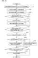
- FIG. 6 is a flowchart for explaining the operation of the electric power steering apparatus according to Embodiment 1 of the present invention.
- the flowchart represented in FIG. 6 is obtained by replacing the step S101 in the flowchart represented in foregoing FIG. 4 by the step S110 and by inserting the steps S111 and S112 between the step S102 and the step S103 in the flowchart represented in foregoing FIG. 4 ; the other parts are substantially the same as those of the flowchart represented in FIG. 4 .
- the flowchart represented in FIG. 6 is periodically implemented by each of the first CPU 10a and the second CPU 10b. Because the first CPU 10a and the second CPU 10b each perform the same processing, the contents of the processing performed by the first CPU 10a will mainly be explained.
- the U-phase motor current Iu1, the V-phase motor current Iv1, and the W-phase motor current Iw1, as the currents flowing in the first armature winding 2a, and a U-phase motor current Iu2, a V-phase motor current Iv2, and a W-phase motor current Iw2, as the currents flowing in the second armature winding 2b, are obtained.
- the second CPU 10b also detects the motor currents flowing in the second armature winding 2b; thus, it may be allowed that through communication between the first CPU 10a and the second CPU 10b, the motor currents flowing in the second armature winding 2b are obtained.
- the U-phase motor current Iu1, the V-phase motor current Iv1, and the W-phase motor current Iw1, which have been detected in the step S101, and the U-phase motor current Iu2, the V-phase motor current Iv2, and the W-phase motor current Iw2, as the currents flowing in the second armature winding 2b, are transformed into the detection current Iq1 of the motor current flowing in the first armature winding 2a and the detection current Iq2 of the motor current flowing in the second armature winding 2b, based on the transformation into the respective [d-q]-axis currents.
- each of the q-axis currents that are [three-phase/d-q]-transformed from the detected U-phase motor current Iu1, the detected V-phase motor current Iv1, and the detected W-phase motor current Iw1 is referred to as a detection current Iq1
- each of the q-axis currents that are [three-phase/d-q]-transformed from the U-phase motor current Iu2, the V-phase motor current Iv2, and the W-phase motor current Iw2 is referred to as a detection current Iq2.
- the first CPU 10a represented in FIG. 5 calculates the effect that is caused by a change in the motor current flowing in the second armature winding 2b and is provided to the detection current Iq1, by use of the first interference block 23a and the first control block 22a.
- detection current Iq2 ⁇ Mq ⁇ s + 1 ⁇ 1 Lq ⁇ s + 1 ⁇ Mq ⁇ s Lq ⁇ s + R detection current Iq2
- Kp, Ki, Lq, R, and Mq are set to 0.4, 75, 100 [ ⁇ H], 0.02 [ ⁇ ], and 50 [ ⁇ H], respectively, and the target current Iq1 is fixed to a rated current 100 [Arms] and that an abnormality in the circuit or the like makes the detection current Iq2 in the second armature winding 2b change from 100 [Arms] to 0 [Arms].
- FIGS. 7A and 7B represents a timing chart at a time when the excessive current determination threshold value is replaced by the value calculated based on the equation (2). That is to say, each of FIGS. 7A and 7B is a timing chart for explaining the operation of the electric power steering apparatus according to Embodiment 1 of the present invention;
- the ordinate in FIG. 7A denotes the target current Iq10 [Arms] in the first armature winding 2a, the detection current Iq1 [Arms], and the excessive current determination threshold value Iq1_thh [Arms] as an abnormality determination threshold value;
- the abscissa denotes the time [sec].
- the ordinate in FIG. 7B denotes the target current Iq20 [Arms] in the second armature winding 2b and the detection current Iq2 [Arms];
- the abscissa denotes the time [sec].
- the detection current Iq2 of the motor current flowing in the second armature winding 2b rapidly changes at a time point "0.1" and hence an effect is provided to the motor current in the first group, the detection current Iq1 of the motor current flowing in the first armature winding 2a does not exceed the threshold value for the excessive current determination current; thus, erroneous detection of a failure can be suppressed.
- Equation (2) has been described, as an equation in a continuous system, by use of the Laplace operator s; however, because calculation utilizing a CPU is performed in a discrete system, it may be allowed that the equation (2) is transformed into an equation in the discrete system, by use of, for example, the bilinear transformation represented in the equation (3) below.
- Embodiment 2 of the present invention the failure determination is performed in the following manner: in the case where it is difficult to calculate the excessive current determination threshold value based on the equation (2) or the equation (5) in foregoing Embodiment 1, in a period with which an excessive current can be determined, the fact that the differential component based on the Laplace operator s in the equation (2) is replaced by the detection current [Iq2(n)-Iq2(n-1)] in the equation (5) is utilized; in the case where the difference value is large, the excessive current determination threshold value is increased, and in the case where the difference value becomes small, the excessive current determination threshold value is restored to the original value.
- FIG. 8 is a flowchart for explaining the operation of the electric power steering apparatus according to Embodiment 2 of the present invention.
- the flowchart in FIG. 8 is different from the flowchart of Embodiment 1 represented in FIG. 6 only in terms of the determination logic for excessive current determination, and the overall circuit diagram in FIG. 1 of the foregoing Embodiment and the block diagram of the control unit in FIG. 5 thereof are the same as those in Embodiment 2; therefore, the explanations therefor will be omitted and the flowchart in FIG. 8 will mainly be explained.
- step S120 in FIG. 8 in the case where the effect of the mutual inductance is large in the first interference block 23a represented in FIG. 5 and hence the difference between the present value of the detection current of the motor current flowing in the second group, i.e., the second armature winding 2b, and the immediately previous value of the detection current in the second group is larger than a first excessive current difference switching determination threshold value Iq_thh1, the step S120 is followed by the step S121, where the excessive current determination threshold value Iq1_thh is increased, for example, to [Iq_typ ⁇ 1.3] so that no erroneous determination is made; then, the step S121 is followed by the step S122.
- the excessive current determination threshold value is not changed, and the step S120 is followed by the step S122.
- step S122 in the case where the difference between the present value of the 2nd group detection current and the immediately previous value of the 2nd group detection current is smaller than a second excessive current difference switching determination threshold value Iq_thh2, with which it can be determined whether or not the effect that is caused by the second group motor current and is provided through the mutual inductance is small, the step S122 is followed by the step S123, where as is the case with the foregoing technology as a basis of the present invention, the excessive current determination threshold value is set to, for example, [Iq_typ ⁇ 1.1]; then, the step 123 is followed by the step S103.
- the excessive current determination threshold value is not changed, and the step S122 is followed by the step S103.
- FIGS. 9A and 9B represents a timing chart at a time when the foregoing determination is performed. That is to say, each of FIGS. 9A and 9B is a timing chart for explaining the operation of the electric power steering apparatus according to Embodiment 2 of the present invention;
- the ordinate in FIG. 9A denotes the target current Iq10 [Arms] in the first armature winding 2a, the detection current Iq1 [Arms], and the excessive current determination threshold value Iq1_thh [Arms] as an abnormality determination threshold value;
- the abscissa denotes the time [sec].
- the ordinate in FIG. 9B denotes the target current Iq20 [Arms] in the second armature winding 2b and the detection current Iq2 [Arms];
- the abscissa denotes the time [sec].
- the excessive current determination threshold value is increased as represented by "X" so that an abnormality in the normal group is prevented from being erroneously determined; in the case where the difference between the present value and the immediately previous value of the second group motor current is small, the excessive current determination threshold value is decreased so that excessive current determination can be performed in a manner the same as that in the technology as a basis of the present invention. Because the steps after and including the step S103 are the same as those in Embodiment 1, the explanation therefor will be omitted.
- Embodiment 3 it can be prevented that in Embodiment 1, when in the case where the motor current in the second group oscillates, the excessive current determination time is switched, the excessive current determination threshold value becomes oscillatory when the motor current oscillates.
- FIG. 10 is a flowchart for explaining the operation of an electric power steering apparatus according to Embodiment 3 of the present invention.
- the steps after and including the step S102 are changed in the flowchart in FIG. 10 .
- the overall circuit diagram in FIG. 1 and the block diagram of the control unit in FIG. 5 in the foregoing embodiment are the same as those in Embodiment 3; therefore, the details thereof will be omitted, and only the flowchart represented in FIG. 10 will be explained.
- the time-extending timer (sw1_timer) is incremented in the step S130.
- the time-extending timer is to prevent it for a predetermined time that a failure determination time is shortened, so that erroneous determination at a time when the failure determination time has been extended once is prevented.
- the steps S130 is followed by the step S120.
- step S120 in the case where the difference between the present value of the 2nd group detection current and the immediately previous value of the 2nd group detection current is larger than the first excessive current difference switching determination threshold value Iq_thh1 and hence it can be determined that the effect that is provided through the mutual inductance in the first interference block 23a represented in FIG. 5 is large (Y), the step S120 is followed by the step S131, where the excessive current determination time is set with the time constant (Lq/R), calculated through the arithmetic expression represented in the equation (1), set to be, for example, thrice as long as a normal time constant, so that it is prevented that the time is so short that the determination is erroneously performed.
- the time constant Lq/R
- time constant (Lq/R), calculated through the arithmetic expression, is set to be thrice as long as the normal time constant is that in order to secure the stability, the time constant is set to a time with which erroneous determination is prevented; in general, the time constant may be set to a time in which the change in the sensor output reaches 95%.
- the time-extending timer sw1_timer is cleared in the step S132 so that after the excessive current determination threshold value has been once switched, the excessive current determination time is not shortened for a predetermined time; then, the step S132 is followed by the step S133.
- step S120 the difference between the present value of the 2nd group detection current and the immediately previous value of the 2nd group detection current is the same as or smaller than the first excessive current difference switching determination threshold value Iq_thh1, the excessive current determination time is not switched, and the step S120 is followed by the step S133.
- step S133 in the case where the difference between the present value of the 2nd group detection current and the immediately previous value of the 2nd group detection current is smaller than the second excessive current difference switching determination threshold value Iq_thh2 and hence it can be determined that the effect that is provided through the mutual inductance in the first interference block 23a represented in FIG.
- step S1330 is followed by the step S134, where the excessive current determination time is switched to Iq1_timer _th2 so as to become as short as that in the technology, which is a basis of the present invention; then, the step S134 is followed by the step S103.
- step S133 the difference between the present value of the 2nd group detection current and the immediately previous value of the 2nd group detection current is the same as or larger than the second excessive current difference switching determination threshold value Iq_thh2 (N), the excessive current determination time is not switched, and the step S133 is followed by the step S103. Because the steps after and including the step S103 are the same as those in Embodiment 1, the explanation therefor will be omitted.
- control items of each of the first CPU 10a and the second CPU 10b change in accordance with a detected abnormality in the motor current.
- the control contents can roughly be classified into the following three kinds.
- the respective detection values of the two sensors are substantially equal to each other; therefore, even in the case where when one of the two sensors is abnormal, the other sensor is utilized, the respective control amounts at a normal time and an abnormal time are hardly different from each other, and hence there exists only an error as large as the device-level difference between the rotation sensors.
- a control amount substantially the same as that at a normal time is outputted, it is not required to change the excessive current determination threshold value; therefore, the excessive current determination threshold value is not intentionally changed.
- the excessive current determination threshold value for detecting an abnormality while the control is continued can be changed in accordance with the control contents in a particular timing.
- the variation width of the torque value corresponding to the value obtained through addition or subtraction is set in order to detect an adhesion abnormality in the torque sensor; in the case where a change larger than the threshold value occurs, it is determined that the sensor is normal; in contrast, in the case where even when addition/subtraction control is performed, no change in the torque value can be detected, it is determined that the sensor is abnormal.
- Two torque sensors are utilized in such a way that in contrast to a normal time, the variation width of the torque, an adhesion determination time, and the like for determining an adhesion abnormality are made variable.
- the threshold value for an abnormality in the sensor can be changed in accordance with the control contents, so that erroneous determination is prevented.
- the control in which the rotation angle is shifted by a predetermined angle from the rotation angle at a normal time.
- the control with such a shift makes it possible to make the torque value, for example, smaller than the target torque value at a normal time, i.e., to make the steering power lighter, and vice versa, conversely.
- Such control contents make it possible that not the abnormality threshold value for the rotation sensor but, for example, the threshold value for a current sensor is changed so that a threshold value corresponding to the "shifting" control is obtained and hence the correctness of the abnormality determination on the current sensor is raised.
- the abnormality threshold value for the other sensor can be changed in accordance with the control contents, so that erroneous determination on the other sensor is prevented. According to the foregoing two specific examples, even when unlike FIG. 1 , all of both the first control unit 1a and the second control unit 1b are not provided, one control unit alone can perform the control.
- the continuous control at an abnormal time is substantially the same as that at a normal time.
- the temperature sensor is utilized for limiting the maximum current supply value for the electric motor 2 at a time when the temperature is high.
- the temperature is estimated from the magnitude of the current, the supply time thereof, and the like and the maximum current supply value is set to a value smaller than the value at a time when the temperature sensor is utilized so that the safety is secured.
- the difference between the respective control amounts at a normal time and at an abnormal time is substantially zero until the current limitation starts to function.
- the threshold value for current detection for example, based on the voltage across the shunt resistor is made changeable.
- the abnormality threshold value for the shunt resistor as a current sensor is set to be smaller than the value at a normal time, so that contribution is made not only to the abnormality determination but also to limitation of the temperature estimation; thus, eventually, there is demonstrated an effect that the overall functionality of the apparatus is prevented from being deteriorated.
- Embodiment 5 of the present invention There will be considered an abnormality in which when in FIG. 1 , part of components in any one of the first inverter circuit 3a, the second inverter circuit 3b, the first driving circuit 11a, and the second driving circuit 11b fail or the first-phase system or the second-phase system of the electric motor 2 fails, as disconnection of the first-phase winding of the electric motor 2, control cannot be performed as per the control command from the first CPU 10a or the second CPU 10b.
- the first CPU 10a or the second CPU 10b can detect this abnormality by monitoring the voltage at each of the portions.
- An initial check makes it possible that immediately after the engine is started, whether or not each of the components and each of connections is normal is preliminarily detected.
- the control can be continued with the remaining two phases and the three phases of the normal armature winding. It is also made possible that the control of the armature winding in which an abnormality exists is stopped and the control is continued with the normal armature winding alone.
- the present invention can be applied to the field of an electric power steering apparatus or a vehicle such as an automobile that is equipped with the electric power steering apparatus.
Landscapes
- Engineering & Computer Science (AREA)
- Chemical & Material Sciences (AREA)
- Combustion & Propulsion (AREA)
- Transportation (AREA)
- Mechanical Engineering (AREA)
- Power Engineering (AREA)
- Power Steering Mechanism (AREA)
- Control Of Ac Motors In General (AREA)
- Steering Control In Accordance With Driving Conditions (AREA)
- Control Of Electric Motors In General (AREA)
Claims (4)
- Un appareil de direction assistée électrique comprenant :un moteur électrique (2) qui produit un couple d'assistance, sur la base d'un couple de direction produit par un conducteur d'un véhicule ; etune unité de commande (1a, 1b) qui commande le moteur électrique (2),le moteur électrique (2) étant équipé de deux ensembles d'enroulements d'induit (2a, 2b) comprenant un premier enroulement d'induit (2a) et un second enroulement d'induit (2b) qui sont constitués de la même manière, outre le fait qu'ils sont agencés de manière à être décalés d'un angle électrique de 120°,l'unité de commande (1a, 1b) étant constituée de deux ensembles d'unités de commande qui sont formées des mêmes éléments constitutifs et qui comprennent une première unité de commande (1a) conçue pour pouvoir contrôler indépendamment le premier enroulement d'induit (2a) et une deuxième unité de commande (1b) conçue pour pouvoir contrôler indépendamment le deuxième enroulement d'induit (2b),la première unité de commande (1a) et la seconde unité de commande (1b) ayant chacuneun circuit d'entrée (12a, 12b) dans lequel des informations provenant d'une pluralité de capteurs (8) sont entrées,un circuit d'entraînement (11a, 11b) qui génère un signal d'entraînement pour entraîner le moteur électrique (2),un circuit inverseur (3a, 3b) commandé par le signal d'entraînement, etune unité de circuit de commande (4a, 4b) dotée d'un processeur (10a, 10b) qui émet un signal de commande au circuit d'entraînement (11a, 11b) pour contrôler le moteur électrique (2), sur la base des informations entrées dans le circuit d'entrée (12a, 12b), etle processeur (10a, 10b) disposant d'un mode de contrôle d'anomalie dans lequel, lors de la détection d'une anomalie dans une partie de la pluralité de capteurs (8), le processeur calcule une quantité de contrôle qui est différente au moins d'une quantité de contrôle à un moment normal, conformément au capteur (8) dans lequel l'anomalie s'est produite et conformément aux contenus de l'anomalie, puis continue un contrôle du moteur électrique (2) ; lorsqu'un contrôle du moteur électrique (2) se poursuit en mode de contrôle d'anomalie, une valeur seuil pour la détection de l'anomalie est modifiée à une valeur différente d'une valeur à un moment normal, conformément aux contenus du contrôle en mode de contrôle d'anomalie, caractérisé en ce quele processeur (10a, 10b) calcule la valeur seuil à laquelle la valeur à un moment normal est modifiée, sur la base d'une inductance mutuelle entre le premier enroulement d'induit (2a) et le second enroulement d'induit (2b).
- L'appareil de direction assistée électrique selon la revendication 1, dans lequel la valeur seuil présente une hystérésis.
- L'appareil de direction assistée électrique selon l'une quelconque des revendications 1 et 2, dans lequel le processeur (10a, 10b) est configuré pour pouvoir modifier un temps de détermination d'anomalie pour la détection de l'anomalie.
- L'appareil de direction assistée électrique selon la revendication 3, dans lequel le temps de détermination d'anomalie présente une hystérésis.
Applications Claiming Priority (1)
| Application Number | Priority Date | Filing Date | Title |
|---|---|---|---|
| PCT/JP2017/013157 WO2018179197A1 (fr) | 2017-03-30 | 2017-03-30 | Dispositif de direction assistée électrique |
Publications (3)
| Publication Number | Publication Date |
|---|---|
| EP3605834A1 EP3605834A1 (fr) | 2020-02-05 |
| EP3605834A4 EP3605834A4 (fr) | 2020-03-04 |
| EP3605834B1 true EP3605834B1 (fr) | 2025-01-01 |
Family
ID=63675032
Family Applications (1)
| Application Number | Title | Priority Date | Filing Date |
|---|---|---|---|
| EP17903924.3A Active EP3605834B1 (fr) | 2017-03-30 | 2017-03-30 | Dispositif de direction assistée électrique |
Country Status (5)
| Country | Link |
|---|---|
| US (1) | US10864937B2 (fr) |
| EP (1) | EP3605834B1 (fr) |
| JP (1) | JP6815483B2 (fr) |
| CN (1) | CN110463026B (fr) |
| WO (1) | WO2018179197A1 (fr) |
Families Citing this family (16)
| Publication number | Priority date | Publication date | Assignee | Title |
|---|---|---|---|---|
| CN108966685A (zh) * | 2016-03-04 | 2018-12-07 | 日本电产株式会社 | 电力转换装置、马达驱动单元、电动助力转向装置和继电器模块 |
| KR20190111118A (ko) * | 2017-03-23 | 2019-10-01 | 히다치 오토모티브 시스템즈 가부시키가이샤 | 모터 시스템 |
| JP6798476B2 (ja) * | 2017-11-30 | 2020-12-09 | 株式会社デンソー | モータ制御装置、モータ駆動システム、及び、モータ制御方法 |
| JPWO2020075693A1 (ja) * | 2018-10-10 | 2021-10-07 | 日本電産株式会社 | モータ制御システム、モータおよび電動パワーステアリング装置 |
| JP2020125996A (ja) * | 2019-02-05 | 2020-08-20 | 日本電産モビリティ株式会社 | 制御装置および制御方法 |
| JP6695473B1 (ja) * | 2019-04-17 | 2020-05-20 | 三菱電機株式会社 | 冗長系センサ装置 |
| JP7188285B2 (ja) * | 2019-06-14 | 2022-12-13 | 株式会社デンソー | 電源システム |
| JP7375357B2 (ja) * | 2019-07-30 | 2023-11-08 | マツダ株式会社 | 車両制御システム |
| JP7205414B2 (ja) * | 2019-08-15 | 2023-01-17 | 株式会社デンソー | 回転電機制御装置 |
| JP7230886B2 (ja) * | 2020-06-17 | 2023-03-01 | 株式会社デンソー | モータ制御装置、及び操舵システム |
| US11431275B2 (en) * | 2020-07-07 | 2022-08-30 | Mando Corporation | Motor control system having redundant electric control unit |
| JP7360560B2 (ja) * | 2020-09-17 | 2023-10-12 | 日立Astemo株式会社 | 電子制御装置 |
| DE102021131083A1 (de) * | 2020-11-30 | 2022-06-02 | Steering Solutions Ip Holding Corporation | Diagnose eines zustands einer eingangsenergie für eine elektrische servolenkung |
| US11936317B2 (en) * | 2021-02-10 | 2024-03-19 | Blue Origin, Llc | Low-voltage fault-tolerant rotating electromechanical actuators, and associated systems and methods |
| US11581832B2 (en) | 2021-02-22 | 2023-02-14 | Infineon Technologies Austria Ag | Motor winding monitoring and switching control |
| KR20240176200A (ko) * | 2023-06-15 | 2024-12-24 | 에이치엘만도 주식회사 | 차량의 조향 제어 장치 및 방법 |
Family Cites Families (16)
| Publication number | Priority date | Publication date | Assignee | Title |
|---|---|---|---|---|
| US7207412B2 (en) * | 2004-02-17 | 2007-04-24 | Denso Corporation | Motor-driven power steering system |
| JP5233178B2 (ja) * | 2007-06-14 | 2013-07-10 | 株式会社ジェイテクト | モータ制御装置及び電動パワーステアリング装置 |
| JP5057908B2 (ja) * | 2007-09-13 | 2012-10-24 | オムロンオートモーティブエレクトロニクス株式会社 | 多相交流モータ駆動装置 |
| JP5436592B2 (ja) | 2012-02-07 | 2014-03-05 | 三菱電機株式会社 | モータ制御装置、モータ制御装置に適用される電流制御方法、およびモータ制御装置を用いた電動パワーステアリング装置 |
| JP5398861B2 (ja) | 2012-03-07 | 2014-01-29 | 三菱電機株式会社 | 多重巻線モータの駆動装置 |
| JP5556845B2 (ja) * | 2012-04-26 | 2014-07-23 | 株式会社デンソー | 3相回転機の制御装置 |
| JP5920050B2 (ja) | 2012-06-21 | 2016-05-18 | 株式会社デンソー | 電動機制御装置、および、これを用いた電動パワーステアリング装置 |
| JP5590076B2 (ja) * | 2012-07-04 | 2014-09-17 | 株式会社デンソー | 多相回転機の制御装置 |
| JP2014072973A (ja) * | 2012-09-28 | 2014-04-21 | Denso Corp | 交流電動機の制御装置 |
| JP5614661B2 (ja) * | 2012-10-09 | 2014-10-29 | 株式会社デンソー | 回転電機制御装置、および、これを用いた電動パワーステアリング装置 |
| JP2015039256A (ja) * | 2013-03-15 | 2015-02-26 | 日本精工株式会社 | モータ制御装置、これを使用した電動パワーステアリング装置及び車両 |
| JP6211443B2 (ja) | 2014-03-14 | 2017-10-11 | 日立オートモティブシステムズ株式会社 | 電動モータの制御装置 |
| JP2016135042A (ja) * | 2015-01-21 | 2016-07-25 | 株式会社リコー | 駆動制御装置、搬送装置、画像形成装置及び駆動制御方法 |
| WO2016135805A1 (fr) * | 2015-02-23 | 2016-09-01 | 三菱電機株式会社 | Dispositif d'entraînement électrique et son procédé de commande |
| WO2016135840A1 (fr) * | 2015-02-24 | 2016-09-01 | 三菱電機株式会社 | Dispositif d'entraînement électrique et dispositif de direction assistée électrique |
| JP6467670B2 (ja) * | 2015-11-04 | 2019-02-13 | 日立オートモティブシステムズ株式会社 | パワーステアリング装置、およびパワーステアリング装置の制御装置 |
-
2017
- 2017-03-30 US US16/345,775 patent/US10864937B2/en not_active Expired - Fee Related
- 2017-03-30 EP EP17903924.3A patent/EP3605834B1/fr active Active
- 2017-03-30 CN CN201780089010.9A patent/CN110463026B/zh active Active
- 2017-03-30 WO PCT/JP2017/013157 patent/WO2018179197A1/fr not_active Ceased
- 2017-03-30 JP JP2019507997A patent/JP6815483B2/ja not_active Expired - Fee Related
Also Published As
| Publication number | Publication date |
|---|---|
| US20200055542A1 (en) | 2020-02-20 |
| US10864937B2 (en) | 2020-12-15 |
| EP3605834A1 (fr) | 2020-02-05 |
| CN110463026A (zh) | 2019-11-15 |
| EP3605834A4 (fr) | 2020-03-04 |
| JP6815483B2 (ja) | 2021-01-20 |
| WO2018179197A1 (fr) | 2018-10-04 |
| CN110463026B (zh) | 2023-09-22 |
| JPWO2018179197A1 (ja) | 2019-11-07 |
Similar Documents
| Publication | Publication Date | Title |
|---|---|---|
| EP3605834B1 (fr) | Dispositif de direction assistée électrique | |
| EP2803556B1 (fr) | Dispositif électrique de direction assistée | |
| CN108778896B (zh) | 电动机控制系统及具备电动机控制系统的电动助力转向装置 | |
| JP6211443B2 (ja) | 電動モータの制御装置 | |
| JP6505257B2 (ja) | 電動パワーステアリング装置 | |
| CN105934879B (zh) | 马达控制装置、使用该马达控制装置的电动助力转向装置以及车辆 | |
| CN104584423B (zh) | 马达控制装置、使用该马达控制装置的电动助力转向装置以及车辆 | |
| EP3331158A1 (fr) | Appareil de direction assistée électrique | |
| CN101401295B (zh) | 电动机控制装置 | |
| CN108352800B (zh) | 电动助力转向装置及其控制方法 | |
| KR101692195B1 (ko) | 전동 모터의 구동 제어 장치 및 구동 제어 방법 | |
| CN102687389B (zh) | 马达驱动系统、马达驱动系统的控制方法、以及行驶装置 | |
| US9174667B2 (en) | Electric power steering | |
| EP3171507B1 (fr) | Dispositif de commande de moteur, dispositif de direction assistée électrique équipé de celui-ci, et véhicule | |
| JP2015202019A (ja) | 電動モータの制御装置 | |
| CN104170242A (zh) | 马达控制装置、使用该马达控制装置的电动动力转向装置以及车辆 | |
| US8892296B2 (en) | Power state diagnosis method and apparatus | |
| US8886411B2 (en) | Power steering system | |
| US8981690B2 (en) | Electric power steering system | |
| JP4371844B2 (ja) | ブラシレスモータ駆動装置 | |
| CN114144347A (zh) | 电动转向装置及方法 | |
| JP7292507B2 (ja) | モータ制御装置、及び電動パワーステアリング装置 | |
| CN118770359A (zh) | 用于操作转向系统的方法、转向系统及载具 | |
| WO2013168279A1 (fr) | Dispositif de direction à assistance électrique |
Legal Events
| Date | Code | Title | Description |
|---|---|---|---|
| STAA | Information on the status of an ep patent application or granted ep patent |
Free format text: STATUS: THE INTERNATIONAL PUBLICATION HAS BEEN MADE |
|
| PUAI | Public reference made under article 153(3) epc to a published international application that has entered the european phase |
Free format text: ORIGINAL CODE: 0009012 |
|
| STAA | Information on the status of an ep patent application or granted ep patent |
Free format text: STATUS: REQUEST FOR EXAMINATION WAS MADE |
|
| REG | Reference to a national code |
Ref country code: DE Ref legal event code: R079 Free format text: PREVIOUS MAIN CLASS: H02P0027060000 Ipc: H02P0029028000 Ref document number: 602017087158 Country of ref document: DE |
|
| 17P | Request for examination filed |
Effective date: 20190409 |
|
| AK | Designated contracting states |
Kind code of ref document: A1 Designated state(s): AL AT BE BG CH CY CZ DE DK EE ES FI FR GB GR HR HU IE IS IT LI LT LU LV MC MK MT NL NO PL PT RO RS SE SI SK SM TR |
|
| AX | Request for extension of the european patent |
Extension state: BA ME |
|
| A4 | Supplementary search report drawn up and despatched |
Effective date: 20200131 |
|
| RIC1 | Information provided on ipc code assigned before grant |
Ipc: B62D 5/04 20060101ALI20200127BHEP Ipc: B62D 6/00 20060101ALI20200127BHEP Ipc: H02P 29/028 20160101AFI20200127BHEP Ipc: H02P 27/06 20060101ALI20200127BHEP |
|
| DAV | Request for validation of the european patent (deleted) | ||
| DAX | Request for extension of the european patent (deleted) | ||
| STAA | Information on the status of an ep patent application or granted ep patent |
Free format text: STATUS: EXAMINATION IS IN PROGRESS |
|
| 17Q | First examination report despatched |
Effective date: 20201203 |
|
| GRAP | Despatch of communication of intention to grant a patent |
Free format text: ORIGINAL CODE: EPIDOSNIGR1 |
|
| STAA | Information on the status of an ep patent application or granted ep patent |
Free format text: STATUS: GRANT OF PATENT IS INTENDED |
|
| INTG | Intention to grant announced |
Effective date: 20240930 |
|
| GRAS | Grant fee paid |
Free format text: ORIGINAL CODE: EPIDOSNIGR3 |
|
| GRAA | (expected) grant |
Free format text: ORIGINAL CODE: 0009210 |
|
| STAA | Information on the status of an ep patent application or granted ep patent |
Free format text: STATUS: THE PATENT HAS BEEN GRANTED |
|
| AK | Designated contracting states |
Kind code of ref document: B1 Designated state(s): AL AT BE BG CH CY CZ DE DK EE ES FI FR GB GR HR HU IE IS IT LI LT LU LV MC MK MT NL NO PL PT RO RS SE SI SK SM TR |
|
| REG | Reference to a national code |
Ref country code: GB Ref legal event code: FG4D |
|
| REG | Reference to a national code |
Ref country code: CH Ref legal event code: EP |
|
| REG | Reference to a national code |
Ref country code: DE Ref legal event code: R096 Ref document number: 602017087158 Country of ref document: DE |
|
| REG | Reference to a national code |
Ref country code: IE Ref legal event code: FG4D |
|
| REG | Reference to a national code |
Ref country code: LT Ref legal event code: MG9D |
|
| REG | Reference to a national code |
Ref country code: NL Ref legal event code: MP Effective date: 20250101 |
|
| REG | Reference to a national code |
Ref country code: AT Ref legal event code: MK05 Ref document number: 1757335 Country of ref document: AT Kind code of ref document: T Effective date: 20250101 |
|
| PG25 | Lapsed in a contracting state [announced via postgrant information from national office to epo] |
Ref country code: NL Free format text: LAPSE BECAUSE OF FAILURE TO SUBMIT A TRANSLATION OF THE DESCRIPTION OR TO PAY THE FEE WITHIN THE PRESCRIBED TIME-LIMIT Effective date: 20250101 |
|
| PG25 | Lapsed in a contracting state [announced via postgrant information from national office to epo] |
Ref country code: FI Free format text: LAPSE BECAUSE OF FAILURE TO SUBMIT A TRANSLATION OF THE DESCRIPTION OR TO PAY THE FEE WITHIN THE PRESCRIBED TIME-LIMIT Effective date: 20250101 |
|
| PG25 | Lapsed in a contracting state [announced via postgrant information from national office to epo] |
Ref country code: PL Free format text: LAPSE BECAUSE OF FAILURE TO SUBMIT A TRANSLATION OF THE DESCRIPTION OR TO PAY THE FEE WITHIN THE PRESCRIBED TIME-LIMIT Effective date: 20250101 |
|
| PG25 | Lapsed in a contracting state [announced via postgrant information from national office to epo] |
Ref country code: ES Free format text: LAPSE BECAUSE OF FAILURE TO SUBMIT A TRANSLATION OF THE DESCRIPTION OR TO PAY THE FEE WITHIN THE PRESCRIBED TIME-LIMIT Effective date: 20250101 |
|
| PG25 | Lapsed in a contracting state [announced via postgrant information from national office to epo] |
Ref country code: IS Free format text: LAPSE BECAUSE OF FAILURE TO SUBMIT A TRANSLATION OF THE DESCRIPTION OR TO PAY THE FEE WITHIN THE PRESCRIBED TIME-LIMIT Effective date: 20250501 Ref country code: NO Free format text: LAPSE BECAUSE OF FAILURE TO SUBMIT A TRANSLATION OF THE DESCRIPTION OR TO PAY THE FEE WITHIN THE PRESCRIBED TIME-LIMIT Effective date: 20250401 |
|
| PG25 | Lapsed in a contracting state [announced via postgrant information from national office to epo] |
Ref country code: HR Free format text: LAPSE BECAUSE OF FAILURE TO SUBMIT A TRANSLATION OF THE DESCRIPTION OR TO PAY THE FEE WITHIN THE PRESCRIBED TIME-LIMIT Effective date: 20250101 |
|
| PG25 | Lapsed in a contracting state [announced via postgrant information from national office to epo] |
Ref country code: LV Free format text: LAPSE BECAUSE OF FAILURE TO SUBMIT A TRANSLATION OF THE DESCRIPTION OR TO PAY THE FEE WITHIN THE PRESCRIBED TIME-LIMIT Effective date: 20250101 Ref country code: PT Free format text: LAPSE BECAUSE OF FAILURE TO SUBMIT A TRANSLATION OF THE DESCRIPTION OR TO PAY THE FEE WITHIN THE PRESCRIBED TIME-LIMIT Effective date: 20250502 |
|
| PG25 | Lapsed in a contracting state [announced via postgrant information from national office to epo] |
Ref country code: BG Free format text: LAPSE BECAUSE OF FAILURE TO SUBMIT A TRANSLATION OF THE DESCRIPTION OR TO PAY THE FEE WITHIN THE PRESCRIBED TIME-LIMIT Effective date: 20250101 Ref country code: GR Free format text: LAPSE BECAUSE OF FAILURE TO SUBMIT A TRANSLATION OF THE DESCRIPTION OR TO PAY THE FEE WITHIN THE PRESCRIBED TIME-LIMIT Effective date: 20250402 |
|
| PG25 | Lapsed in a contracting state [announced via postgrant information from national office to epo] |
Ref country code: AT Free format text: LAPSE BECAUSE OF FAILURE TO SUBMIT A TRANSLATION OF THE DESCRIPTION OR TO PAY THE FEE WITHIN THE PRESCRIBED TIME-LIMIT Effective date: 20250101 |
|
| PG25 | Lapsed in a contracting state [announced via postgrant information from national office to epo] |
Ref country code: CZ Free format text: LAPSE BECAUSE OF FAILURE TO SUBMIT A TRANSLATION OF THE DESCRIPTION OR TO PAY THE FEE WITHIN THE PRESCRIBED TIME-LIMIT Effective date: 20250101 |
|
| PG25 | Lapsed in a contracting state [announced via postgrant information from national office to epo] |
Ref country code: SE Free format text: LAPSE BECAUSE OF FAILURE TO SUBMIT A TRANSLATION OF THE DESCRIPTION OR TO PAY THE FEE WITHIN THE PRESCRIBED TIME-LIMIT Effective date: 20250101 |
|
| P01 | Opt-out of the competence of the unified patent court (upc) registered |
Free format text: CASE NUMBER: UPC_APP_4903_3605834/2025 Effective date: 20250827 |
|
| REG | Reference to a national code |
Ref country code: DE Ref legal event code: R097 Ref document number: 602017087158 Country of ref document: DE |
|
| PG25 | Lapsed in a contracting state [announced via postgrant information from national office to epo] |
Ref country code: SM Free format text: LAPSE BECAUSE OF FAILURE TO SUBMIT A TRANSLATION OF THE DESCRIPTION OR TO PAY THE FEE WITHIN THE PRESCRIBED TIME-LIMIT Effective date: 20250101 |
|
| PG25 | Lapsed in a contracting state [announced via postgrant information from national office to epo] |
Ref country code: DK Free format text: LAPSE BECAUSE OF FAILURE TO SUBMIT A TRANSLATION OF THE DESCRIPTION OR TO PAY THE FEE WITHIN THE PRESCRIBED TIME-LIMIT Effective date: 20250101 |
|
| PG25 | Lapsed in a contracting state [announced via postgrant information from national office to epo] |
Ref country code: MC Free format text: LAPSE BECAUSE OF FAILURE TO SUBMIT A TRANSLATION OF THE DESCRIPTION OR TO PAY THE FEE WITHIN THE PRESCRIBED TIME-LIMIT Effective date: 20250101 |
|
| PG25 | Lapsed in a contracting state [announced via postgrant information from national office to epo] |
Ref country code: IT Free format text: LAPSE BECAUSE OF FAILURE TO SUBMIT A TRANSLATION OF THE DESCRIPTION OR TO PAY THE FEE WITHIN THE PRESCRIBED TIME-LIMIT Effective date: 20250101 |
|
| PG25 | Lapsed in a contracting state [announced via postgrant information from national office to epo] |
Ref country code: EE Free format text: LAPSE BECAUSE OF FAILURE TO SUBMIT A TRANSLATION OF THE DESCRIPTION OR TO PAY THE FEE WITHIN THE PRESCRIBED TIME-LIMIT Effective date: 20250101 |
|
| PG25 | Lapsed in a contracting state [announced via postgrant information from national office to epo] |
Ref country code: RO Free format text: LAPSE BECAUSE OF FAILURE TO SUBMIT A TRANSLATION OF THE DESCRIPTION OR TO PAY THE FEE WITHIN THE PRESCRIBED TIME-LIMIT Effective date: 20250101 |
|
| REG | Reference to a national code |
Ref country code: CH Ref legal event code: H13 Free format text: ST27 STATUS EVENT CODE: U-0-0-H10-H13 (AS PROVIDED BY THE NATIONAL OFFICE) Effective date: 20251023 |
|
| PG25 | Lapsed in a contracting state [announced via postgrant information from national office to epo] |
Ref country code: SK Free format text: LAPSE BECAUSE OF FAILURE TO SUBMIT A TRANSLATION OF THE DESCRIPTION OR TO PAY THE FEE WITHIN THE PRESCRIBED TIME-LIMIT Effective date: 20250101 |
|
| PLBE | No opposition filed within time limit |
Free format text: ORIGINAL CODE: 0009261 |
|
| STAA | Information on the status of an ep patent application or granted ep patent |
Free format text: STATUS: NO OPPOSITION FILED WITHIN TIME LIMIT |
|
| PG25 | Lapsed in a contracting state [announced via postgrant information from national office to epo] |
Ref country code: LU Free format text: LAPSE BECAUSE OF NON-PAYMENT OF DUE FEES Effective date: 20250330 |
|
| 26N | No opposition filed |
Effective date: 20251002 |
|
| REG | Reference to a national code |
Ref country code: BE Ref legal event code: MM Effective date: 20250331 |
|
| GBPC | Gb: european patent ceased through non-payment of renewal fee |
Effective date: 20250401 |
|
| PG25 | Lapsed in a contracting state [announced via postgrant information from national office to epo] |
Ref country code: GB Free format text: LAPSE BECAUSE OF NON-PAYMENT OF DUE FEES Effective date: 20250401 |
|
| PG25 | Lapsed in a contracting state [announced via postgrant information from national office to epo] |
Ref country code: BE Free format text: LAPSE BECAUSE OF NON-PAYMENT OF DUE FEES Effective date: 20250331 |
|
| PG25 | Lapsed in a contracting state [announced via postgrant information from national office to epo] |
Ref country code: CH Free format text: LAPSE BECAUSE OF NON-PAYMENT OF DUE FEES Effective date: 20250331 |
|
| PG25 | Lapsed in a contracting state [announced via postgrant information from national office to epo] |
Ref country code: IE Free format text: LAPSE BECAUSE OF NON-PAYMENT OF DUE FEES Effective date: 20250330 |
|
| PGFP | Annual fee paid to national office [announced via postgrant information from national office to epo] |
Ref country code: DE Payment date: 20260204 Year of fee payment: 10 |
|
| PGFP | Annual fee paid to national office [announced via postgrant information from national office to epo] |
Ref country code: FR Payment date: 20260209 Year of fee payment: 10 |