EP3606037B1 - Lentille liquide, module de caméra et dispositif optique le comprenant - Google Patents
Lentille liquide, module de caméra et dispositif optique le comprenant Download PDFInfo
- Publication number
- EP3606037B1 EP3606037B1 EP18770719.5A EP18770719A EP3606037B1 EP 3606037 B1 EP3606037 B1 EP 3606037B1 EP 18770719 A EP18770719 A EP 18770719A EP 3606037 B1 EP3606037 B1 EP 3606037B1
- Authority
- EP
- European Patent Office
- Prior art keywords
- voltage
- electrode
- individual
- individual electrode
- liquid lens
- Prior art date
- Legal status (The legal status is an assumption and is not a legal conclusion. Google has not performed a legal analysis and makes no representation as to the accuracy of the status listed.)
- Active
Links
Images


Classifications
-
- G—PHYSICS
- G02—OPTICS
- G02B—OPTICAL ELEMENTS, SYSTEMS OR APPARATUS
- G02B26/00—Optical devices or arrangements for the control of light using movable or deformable optical elements
- G02B26/004—Optical devices or arrangements for the control of light using movable or deformable optical elements based on a displacement or a deformation of a fluid
- G02B26/005—Optical devices or arrangements for the control of light using movable or deformable optical elements based on a displacement or a deformation of a fluid based on electrowetting
-
- H—ELECTRICITY
- H04—ELECTRIC COMMUNICATION TECHNIQUE
- H04N—PICTORIAL COMMUNICATION, e.g. TELEVISION
- H04N23/00—Cameras or camera modules comprising electronic image sensors; Control thereof
- H04N23/60—Control of cameras or camera modules
- H04N23/65—Control of camera operation in relation to power supply
-
- G—PHYSICS
- G02—OPTICS
- G02B—OPTICAL ELEMENTS, SYSTEMS OR APPARATUS
- G02B27/00—Optical systems or apparatus not provided for by any of the groups G02B1/00 - G02B26/00, G02B30/00
- G02B27/64—Imaging systems using optical elements for stabilisation of the lateral and angular position of the image
-
- G—PHYSICS
- G02—OPTICS
- G02B—OPTICAL ELEMENTS, SYSTEMS OR APPARATUS
- G02B27/00—Optical systems or apparatus not provided for by any of the groups G02B1/00 - G02B26/00, G02B30/00
- G02B27/64—Imaging systems using optical elements for stabilisation of the lateral and angular position of the image
- G02B27/646—Imaging systems using optical elements for stabilisation of the lateral and angular position of the image compensating for small deviations, e.g. due to vibration or shake
-
- G—PHYSICS
- G02—OPTICS
- G02B—OPTICAL ELEMENTS, SYSTEMS OR APPARATUS
- G02B3/00—Simple or compound lenses
- G02B3/12—Fluid-filled or evacuated lenses
- G02B3/14—Fluid-filled or evacuated lenses of variable focal length
-
- H—ELECTRICITY
- H04—ELECTRIC COMMUNICATION TECHNIQUE
- H04N—PICTORIAL COMMUNICATION, e.g. TELEVISION
- H04N23/00—Cameras or camera modules comprising electronic image sensors; Control thereof
-
- H—ELECTRICITY
- H04—ELECTRIC COMMUNICATION TECHNIQUE
- H04N—PICTORIAL COMMUNICATION, e.g. TELEVISION
- H04N23/00—Cameras or camera modules comprising electronic image sensors; Control thereof
- H04N23/50—Constructional details
- H04N23/55—Optical parts specially adapted for electronic image sensors; Mounting thereof
-
- H—ELECTRICITY
- H04—ELECTRIC COMMUNICATION TECHNIQUE
- H04N—PICTORIAL COMMUNICATION, e.g. TELEVISION
- H04N23/00—Cameras or camera modules comprising electronic image sensors; Control thereof
- H04N23/60—Control of cameras or camera modules
Definitions
- Embodiments relate to a camera module including a liquid lens and a method for controlling the same. More particularly, embodiments relate to a camera module and an optical device which include a control module or a control device for controlling a liquid lens capable of adjusting a focal length using electrical energy.
- EP 1 870 740 A1 discloses a drive circuitry for driving a plurality of liquid lenses.
- Each liquid lens comprises first and second immiscible liquids. An interface between the first and second liquids is movable by electrowetting by application of a drive voltage signal.
- the drive circuitry is arranged to generate an independent drive voltage Signal for each of the liquid lenses.
- KR 100 462 520 B1 relates to a liquid lens driving circuit that generates a liquid lens driving signal and to a liquid lens driving circuit integrated with the liquid lens driving circuit.
- the liquid lens driving circuit generates a high voltage driving signal from a low voltage source.
- a differential type driving signal is generated to improve the root mean square (RMS) voltage between two electrodes of the liquid lens applied by the high voltage driving signal that drives the liquid lens.
- RMS root mean square
- the various capture functions include, for example, an auto-focus (AF) function and an optical image stabilization (OIS) function for compensating for tremor of user's hands or counteracting shaking of an optical device.
- AF auto-focus
- OIS optical image stabilization
- Such capture functions may be implemented through a method of combining multiple lenses to directly move the lenses. However, if the number of lenses increases, the size of the optical device may increase.
- AF and OIS functions a module of multiple lenses which are fixed in a lens holder and have arranged optical axes moves or tilts in the direction of the optical axes or in a vertical direction of the optical axes and an additional lens driving device is used to drive the lens module.
- the lens driving device has high power consumption and is thick in thickness because a cover glass for protecting the lens module should be provided separately from a camera module. Accordingly, studies on a liquid lens for performing the AF and OIS functions by electrically adjusting the curvature of an interface of two types of liquid have been conducted.
- a high driving voltage is generated to drive the lens even by a low voltage, using a switching circuit and a negative voltage, thereby reducing the size of an integrated circuit for controlling the lens.
- a positive voltage and a negative voltage are alternately supplied to a common electrode even when a low voltage is supplied to a plurality of terminals of a lens capable of adjusting a focal length, thereby generating a high voltage for driving the lens.
- distortion of an interface which may occur when the difference in voltage between electrodes increases is prevented by floating partial electrodes to control a driving voltage of a lens capable of adjusting a focal length, thereby more stably performing optical image stabilization, i.e., an OIS function.
- a pulse of a voltage provided to a common terminal and a plurality of terminals is controlled in detail using floating to control a driving voltage of a lens capable of adjusting a focal length, thereby raising resolution and a range of lens control.
- embodiments are applied to a portable device and a circuit for controlling a lens adjusting a focal length in correspondence to a driving voltage applied between a common terminal and a plurality of terminals uses a ground voltage as a power voltage, thereby reducing power consumption of the circuit and a camera module.
- the invention is as defined in claim 1.
- the second voltage generator may include a charge pump for receiving the first voltage from the first voltage generator and changing a polarity of the first voltage to output the first voltage having the changed polarity.
- the first voltage may have a positive polarity and the second voltage generator may output the second voltage of a negative polarity having the same magnitude as the first voltage independently of the first voltage generator.
- Switching elements included in at least one first switch may be commonly disposed in the plural subelectrodes of the individual electrode and switching elements included in plural third switches may be independently disposed in each subelectrode of the individual electrode.
- Subelectrodes of at least two individual electrodes disposed at a symmetrical location based on the center of the liquid lens among plural electrode sectors may be floated during a preset time.
- All of the subelectrodes of the individual electrode may be floated during a preset time.
- a method of controlling a liquid lens having a plurality of subelectrodes including a first subelectrode may include applying a first voltage, a second voltage having a polarity opposite to the first voltage, or a ground voltage to the first subelectrode; floating the first subelectrode during a preset time; and applying the first voltage, the second voltage, or the ground voltage after floating the first subelectrode during a preset time.
- the third switch may include a first switch element connected to the first switch and a second switch element connected to the second switch and cut off the first switch element and the second switch element during a preset time to prevent the first voltage, the second voltage, or the ground voltage from being transmitted to the at least one subelectrode.
- Embodiments may achieve a compact size of an element constituting an integrated circuit for controlling a lens by generating a driving voltage of the lens capable of adjusting a focal length using a negative voltage.
- embodiments may reduce the size of a circuit for generating a supply voltage for controlling a lens capable of adjusting a focal length, and raise productivity and decrease manufacturing cost because resolution and a range may be ensured even by a low-end control circuit.
- embodiments increase a range within which an image may be corrected through optical image stabilization (OIS) and perform efficient image correction by performing a stable optical image stabilization function, i.e., OIS function even when there is a big difference in driving voltage between electrodes in a process of controlling movement of an interface in a liquid lens.
- OIS optical image stabilization
- relational terms such as “on”/"upper part”/"above”, “under”/”lower part”/”below,” and the like, are used solely to distinguish one entity or element from another entity or element without necessarily requiring or implying any physical or logical relationship or order between such entities or elements.
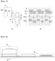
- FIG. 1 illustrates problems of a method of controlling a lens capable of adjusting a focal length using electrical energy.
- FIG. 1(a) illustrates a control circuit for applying a driving voltage to a lens
- FIG. 1(b) is a waveform diagram illustrating a method of applying a driving voltage to a lens.
- the control circuit may include a voltage booster 12 for receiving a supply voltage VIN and boosting the level of the received voltage, a voltage stabilizer 14 for stabilizing the output of the voltage booster 12, and a switching unit 16 for selectively supplying the output of the voltage booster 12 to a lens 10.
- the switching unit 16 may include a circuit configuration typically called an H bridge. A high voltage output from the voltage booster 12 is applied as a power voltage of the switching unit 16. The switching unit 16 may selectively supply the applied power voltage and a ground voltage to both terminals of the lens 10.
- a voltage of a pulse type having a predetermined width may be applied to the both terminals of the lens 10, i.e., a common terminal C0 and an individual electrode L1.
- a driving voltage Vop applied to the lens 10 corresponds to the difference in voltage between the common terminal C0 and the individual electrode L1. Accordingly, if a voltage of the same level is applied with a time difference to the common terminal C0 and the individual electrode L1, it may be understood that the driving voltage Vop of 0 V is applied to the lens 10.
- an operating voltage output from the voltage booster 12 has a level of about 70 V. Therefore, elements included in the switching unit 16 need to be driven at a high voltage of a level of 70 V.
- the elements that should be driven at the high voltage have difficulty in being miniaturized.
- the elements that may be driven at the high voltage should satisfy characteristics of a breakdown voltage, specific on-resistance, a safe operating area (SOA), and a maximum forward voltage. If the elements operating at the high voltage are made excessively small, an element such as a transistor may not perform a function of switching or amplification. For these reasons, it is difficult to miniaturize a control circuit for supplying a driving voltage of the lens 10 and production cost may be raised due to low productivity.
- FIG. 2 is a cross-sectional view of a camera module according to an embodiment.
- the camera module illustrated in FIG. 2 may include a lens assembly 22, a control circuit 24, and an image sensor 26.
- the lens assembly 22 may include a plurality of lenses.
- the plural lenses may include a first lens, a focal length of which is adjusted in correspondence to a driving voltage applied between a common terminal and a plurality of individual electrodes.
- the control circuit 24 may serve to supply the driving voltage to the first lens.
- the image sensor 26 is aligned with the lens assembly 22 and may convert light transmitted through the lens assembly 22 into an electrical signal.
- the camera module may include the plural circuits 24 and 26 and the lens assembly 22 including a plurality of lenses, which are formed on one printed circuit board (PCB), but this is purely exemplary and embodiments are not limited thereto.
- the construction of the control circuit 24 may be differently designed according to specifications required for the camera module. Particularly, if the magnitude of an operating voltage applied to the lens assembly 22 is reduced, the control circuit 24 may be implemented by a single chip. Then, the size of the camera module mounted in a portable device may be further reduced.
- FIG. 3 is a cross-sectional view of the lens assembly 22 included in the camera module according to an embodiment.
- the lens assembly 22 illustrated in FIG. 3 may include a first lens unit 100, a second lens unit 200, a liquid lens 300, a lens housing 400, and a connection terminal 500.
- the structure of the lens assembly 22 illustrated in FIG. 3 is purely exemplary and may differ according to specifications required for the camera module.
- the liquid lens unit 300 is located between the first lens unit 100 and the second lens unit 200.
- the liquid lens unit 300 may be located on (in front of) the first lens unit 100.
- the first lens unit 100 is disposed at the front portion of the lens assembly and light is incident thereon from the exterior of the lens assembly.
- the first lens unit 100 may include at least one lens.
- the first lens unit 100 may include two or more lenses arranged based on a central axis PL to form an optical system.
- the first lens unit 100 and second lens unit 200 may be mounted in the lens housing 400.
- a through hole may be formed in the lens housing 400 and the first lens unit 100 and the second lens unit 200 may be arranged in the through hole.
- the liquid lens unit 300 may be inserted into a space between the first lens unit 100 and the second lens unit 200 arranged in the lens housing 400.
- the first lens unit 100 may include an exposure lens 110.
- the exposure lens 110 is extruded to the exterior of the lens housing 400 so that the exposure lens 110 may be externally exposed. Since the exposure lens 110 is exposed to the exterior, the surface thereof may be damaged. If the surface of the exposure lens 110 is damaged, the picture quality of an image captured by the camera module may be deteriorated.
- a cover glass (not illustrated) may be disposed on the exposure lens 110 or a coating layer (not illustrated) may be formed on the exposure lens 110.
- the exposure lens 110 may be formed of an abrasion-resistant material.
- the second lens unit 200 may be disposed at the back side of the first lens unit 100 and the liquid lens unit 300 and light incident from the exterior to the first lens unit 100 may pass through the liquid lens unit 300 and then may be incident to the second lens unit 200.
- the second lens unit 200 may be separated from the first lens unit 100 and may be disposed in the through hole formed in the lens housing 400.
- the second lens unit 200 may include at least one lens. If the second lens unit 200 includes two or more lenses, the plural lenses may be arranged based on the central axis PL to form an optical system.
- the liquid lens unit 300 may be disposed between the first lens unit 100 and the second lens unit 200 and may be inserted into an insertion hole 410 of the lens housing 400.
- the liquid lens unit 300 may also be arranged based on the central axis PL, like the first lens unit 100 and the second lens unit 200.
- a lens region 310 may be included in the liquid lens unit 300.
- the lens region 310 is a region to which light which has passed through the first lens unit 100 is transmitted and may include liquid in at least a part thereof.
- the lens region 310 may include two types of liquids, i.e., a conductive liquid and a non-conductive liquid.
- the conductive liquid and the non-conductive liquid may not be mixed to form an interface.
- the interface of the conductive liquid and the nonconductive liquid may be modified by a driving voltage applied through the connection terminal 500, so that the curvature and focal length of the liquid lens unit 300 may be changed. If the modification of the interface and change of the curvature of the liquid lens unit are controlled, the liquid lens unit 300, and the lens assembly and the camera module including the liquid lens unit 300 may perform an optical zoom function, an AF function, and an OIS function, etc.
- FIG. 4(a) and FIG. 4(b) illustrate a lens, a focal length of which is adjusted in correspondence to a driving voltage.
- FIG. 4(a) illustrates a first lens 28 included in the lens assembly 22 (refer to FIG. 3) and FIG. 4(b) is an equivalent circuit of the lens 28.
- the lens 28, a focal length of which is adjusted according to a driving voltage may receive an operating voltage through individual electrodes L1, L2, L3, and L4.
- the individual electrodes may have the same angular distance and may include four individual electrodes arranged in different directions. If the operating voltage is applied through the individual electrodes L1, L2, L3, and L4, an interface of a conductive liquid and a nonconductive liquid formed in the lens region 310 may be modified.
- the lens 28 may be regarded as a plurality of capacitors 30 each having one terminal configured to receive the operating voltage from the different individual electrodes L1, L2, L3, and L4 and the other terminal connected to a common terminal C0.
- each of the plural capacitors 30 included in the equivalent circuit may have small capacitance of a level of about 200 pico-Farad (pF) .
- FIG. 5 illustrates movement of an interface of a liquid lens.
- FIGS. 5(a) to FIG. 5(d) illustrate movements of interfaces 30a, 30b, 30c, and 30d which may occur when driving voltages are applied to individual electrodes L1, L2, L3, and L4 of the liquid lens 28.
- an interface 30a may maintain a shape similar to a circle.
- a distance LH between the first and third individual electrodes L1 and L3 is substantially the same as a distance LV between the second and forth individual electrodes L2 and L4 and movement of the interface 30a (e.g., a slant angle) may keep equilibrium.
- each of the driving voltages applied to the first and third individual electrodes L1 and L3 of the liquid lens 28, respectively is slightly lower than each of the driving voltages applied to the second and fourth individual electrodes L2 and L4, respectively.
- the length of the horizontal direction i.e., the distance LH between the first and third individual electrodes L1 and L3
- the distance LV between the second and fourth individual electrodes L2 and L4 may be shorter than the distance of the vertical direction (i.e., the distance LV between the second and fourth individual electrodes L2 and L4).
- the respective driving voltages applied to the first and third individual electrodes L1 and L3 of the liquid lens 28 and the respective driving voltages applied to the second and fourth individual electrodes L2 and L4 of the liquid lens 28 are different to some degree, whether the liquid lens 28 is distorted and a distortion level of the liquid lens 28 may differ according to the structure and properties of the liquid lens 28. For example, a slant of 0.6° or more in a specific direction is compensated for by an OIS function, the interface 30c of the liquid lens 28 may be twisted.
- the difference between the length of the horizontal direction (i.e., the length LH between the first and third individual electrodes L1 and L3) and the length of the vertical direction (i.e., the distance LV between the second and fourth individual electrodes L2 and L4) may further increase compared with the case of the interface 30b described with reference to FIG. 5 (b) .
- the outer shape, i.e., the edge, of the interface 30d can be prevented from being curved or the interface 30d may be prevented from being twisted, by floating the first and third individual electrodes L1 and L3 in a state in which the driving voltages applied to the second and fourth individual electrodes L2 and L4 are maintained.
- floating state which is well-known to the person skilled in the art, may mean an unknown state because the state is floated.
- the liquid lens 28 may be prevented from being distorted.
- FIG. 6 is a diagram for explaining a first driving method of a liquid lens according to an embodiment.
- an interface of the liquid lens may be controlled by applying preset voltages (e.g., a ground voltage of 0 V and a high voltage of 70 V) to a plurality of individual electrodes L1, L2, L3, and L4 and a common electrode C0 of the liquid lens.
- preset voltages e.g., a ground voltage of 0 V and a high voltage of 70 V
- the ground voltage may be a reference potential in a control circuit and a reference voltage of the control circuit.
- Movement of the interface of the liquid lens may be controlled by potential differences between the individual electrodes and the common electrode.
- To apply a ground voltage of 0 V to one electrode of the liquid lens and a high voltage of 70 V to another electrode of the liquid lens an operation of turning on a switch connected between the ground voltage 0 V and one electrode and on operation of turning on a switch capable of supplying the high voltage of 70 V output from a voltage booster in the control circuit to the other electrode may be performed.
- FIG. 7 is a diagram for explaining a second driving method of a liquid lens according to an embodiment.
- FIG. 8 is a diagram illustrating a first embodiment of a control circuit.
- the control circuit is a circuit for applying an operating voltage to the lens 28 (refer to FIG. 4 ) which is included in the lens assembly 22 and has a focal distance adjusted according to a driving voltage.
- the lens 28 may be regarded as including the plural capacitors 30 and the individual electrodes L1, L2, L3, and L4 for supplying the operating voltage to the respective capacitors 30 may be independently controlled.
- one capacitor 30 connected to one individual terminal will be explained by way of example to describe the control circuit.
- the control circuit illustrated in FIG. 8 may include an individual electrode controller 34 and a common terminal controller 36.
- the individual electrode controller 34 and the common terminal controller 36 may receive a ground voltage as a power voltage and receive an operating voltage having the magnitude of 1/2 of a driving voltage from a voltage booster 32.
- the individual electrode controller 34 may supply the operating voltage to the individual electrode of the capacitor 30 in the form of a positive voltage and a negative voltage and the common terminal controller 36 may supply the operating voltage to the common terminal of the capacitor 30 in the form of the positive voltage and the negative voltage.
- the individual electrode controller 34 may supply the operating voltage to the individual electrode in the form of the positive voltage and the negative voltage when a ground voltage, a reference potential, or a reference voltage is regarded as 0 V, and the common terminal controller 36 may supply the operating voltage to the common electrode of the capacitor 30 in the form of the positive voltage and the negative voltage.
- the individual electrode controller 34 and the common terminal controller 36 may have substantially the same construction. Hereinafter, the individual electrode controller 34 will be described in more detail.
- the individual electrode controller 34 may include a charge pump 46 for adjusting the operating voltage provided by a voltage booster 32 to a negative voltage.
- the individual electrode controller 34 may also include a switching unit including a plurality of switches.
- the switching unit may include a first switch 42 for selecting one of the ground voltage and the operating voltage, a second switch 48 for selecting one of an output of the charge pump 46 and the ground voltage, and a third switch 44 for selecting one of outputs of the first switch 42 and the second switch 48 and applying the selected output to the individual electrode of the capacitor 30.
- each of the first switch 42, the second switch 48, and the third switch 44 may include at least one transistor.
- each of the switches 42, 48, 44 may include two transistors.
- the first switch 42 and the second switch 48 in the individual electrode controller 34 may use the ground voltage as a bias voltage to determine the operating voltage applied to the individual electrode or the common electrode of the capacitor 30.
- the control circuit may further include the voltage booster 32 for converting a supply voltage Vin to the magnitude of the operating voltage.
- the supply voltage input to the voltage booster 32 may have a level of 2.5 V to 3.0 V and the operating voltage output by the voltage booster 32 may have a level of 30 V to 40 V.
- the supply voltage input to the voltage booster 32 may be an operating voltage of a portable device in which a camera module is mounted.
- the individual electrode controller 34 and the common terminal controller 36 receive the ground voltage as the power voltage. Therefore, power consumption may be reduced as compared with the case in which the operating voltage, which is the output of the voltage booster 32, is applied as the power voltage. For example, when it is unnecessary for the control circuit to operate, if the operating voltage, which is the output of the voltage booster 32, is applied as the power voltage, the operating voltage is not transmitted to the capacitor 30 by the switches 42, 44, and 48. However, since the operating voltage continues to be applied to the switches, power consumption may occur. It may be important to reduce power consumption in the camera module mounted in the portable device. Therefore, the output of the voltage booster 32 is not provided as the power voltage of the individual electrode controller 34 and the common terminal controller 36 and is connected to the switch 42.
- FIG. 9 illustrates a second embodiment of the control circuit.
- control circuit connected to a voltage booster 32 for receiving a supply voltage Vin and outputting an operating voltage may control a voltage applied to an individual electrode of a capacitor 30.
- the control circuit may include a first voltage stabilizer 52 for stabilizing the output of the voltage booster 32.
- the output of the voltage booster 32 may be transmitted to a first charge pump 46.
- the first charge pump 46 may include a first element for selectively transmitting a ground voltage, a second element for selectively transmitting an operating voltage, and a first capacitor located between the outputs of the first and second elements and a switching unit.
- Each of the first and second elements may include a transistor.
- a first switch 42 for selecting one of the ground voltage and the operating voltage may include a third element for selectively transmitting the ground voltage and a fourth element for selectively transmitting the operating voltage.
- a second switch 48 for selecting one of the output of the first charge pump 46 and the ground voltage may include a fifth element for selectively transmitting the output of the first charge pump 46 and a sixth element for selectively transmitting the ground voltage.
- both the first switch 42 and the second switch 48 may selectively transmit the ground voltage. Since both the first switch 42 and the second switch 48 may transmit the ground voltage as the operating voltage applied to one terminal of the capacitor 30, if one of the two switches transmits the operating voltage, the other may be connected to the ground voltage. Therefore, a positive voltage or a negative voltage of the operating voltage may be determined.
- a third switch 44 for selecting one of the outputs of the first switch 42 and the second switch 48 and applying the selected output to the individual electrode of the capacitor 30 may include a seventh element for selectively transmitting the output of the first switch 42 and an eighth element for selectively transmitting the output of the second switch 48.
- the control circuit may include a common terminal controller 36.
- the common terminal controller 36 may include a second voltage stabilizer 54, a second charge pump 66, a fourth switch 62, a fifth switch 68, and a sixth switch 64.
- the second voltage stabilizer 54 may have the same construction as the first voltage stabilizer 54 and the second charge pump 66 may have the same construction as the first charge pump 46.
- the fourth switch 62 may have the same construction as the first switch 42
- the fifth switch 68 may have the same construction as the second switch 48
- the sixth switch 64 may have the same construction as the third switch 44.
- FIG. 10 is a cross-sectional diagram of a liquid lens according to an embodiment.
- a liquid lens 28 may include a liquid, a first plate 114, and electrodes.
- Liquids 122 and 124 included in the liquid lens 28 may include a conductive liquid and a nonconductive liquid.
- the first plate 114 may include a cavity 150 in which the conductive liquid and the nonconductive liquid are disposed.
- the cavity 150 may include a slanted surface.
- Electrodes 132 and 134 may be disposed on the first plate 114. That is, the electrodes 132 and 134 may be disposed at the upper portion of the first plate 114 and the lower portion of the first plate 114, respectively.
- the liquid lens 28 may further include a second plate 112 which may be disposed at the upper (or lower) portion of the electrodes 132 and 134.
- the liquid lens 28 may further include a third plate 116 which may be disposed at the lower (or upper) portion of the electrodes 132 and 134. As illustrated, an embodiment of the liquid lens 28 may include an interface 130 formed by the two different liquids 122 and 124. An embodiment of the liquid lens 28 may include at least one or more substrates 142 and 144 for supplying a voltage to the liquid lens 28. An edge of the liquid lens 28 may be thinner in thickness than the center of the liquid lens 28.
- the liquid lens 28 includes two different liquids, for example, the conductive liquid 122 and the nonconductive liquid 124.
- the curvature and shape of the interface 130 formed by the two liquids may be adjusted by a driving voltage applied to the liquid lens 28.
- the driving voltage supplied to the liquid lens 28 may be transmitted through the first substrate 142 and the second substrate 144.
- the second substrate 144 may transmit four distinguishable individual driving voltages and the first substrate 142 may transmit one common voltage. Voltages supplied through the second substrate 144 and the first substrate 142 may be applied to the plural electrodes 134 and 132 exposed to each edge of the liquid lens 28.
- the liquid lens 28 may include the third plate 116 and the second plate 112 having a transparent material and the first plate 114 which is disposed between the third plate 116 and the second plate 112.
- the first plate 114 may include an opening area having a slanted surface which is predetermined.
- the liquid lens 28 may include the cavity 150 determined by the third plate 116, the second plate 112, and the opening area of the first plate 114.
- the cavity 150 may be filled with the two liquids 122 and 124 having different properties (e.g., a conductive liquid and a nonconductive liquid) and the interface 130 may be formed between the two liquids 122 and 124 having different properties.
- the liquid lens 28 may further include an insulation layer 118 disposed on the two electrodes 132 and 134 disposed on the upper portion and lower portion of the first plate 114 and on a slanted surface at which the conductive liquid may touch.
- the insulation layer 118 covers one electrode (e.g., the second electrode 134) of the two electrodes 132 and 134 and exposes a part of the other electrode (e.g., the first electrode 132) so that electrical energy may be applied to the conductive liquid (e.g., 122).
- the first electrode 132 may include at least one electrode sector (e.g., C0) and the second electrode 134 may include two or more electrode sectors (e.g., L1, L2, L3, and L4 of FIG. 4 ).
- the second electrode 134 may include a plurality of electrode sectors which are sequentially disposed clockwise based on an optical axis.
- an electrode sector may be called a subelectrode.
- One or more substrates 142 and 144 may be connected to transmit a driving voltage to the two electrodes 132 and 134 included in the liquid lens 28.
- a focal length of the liquid lens 28 may be adjusted by changing the curvature and slant level of the interface 130 formed in the liquid lens according to the driving voltage.
- FIG. 11 illustrates a third embodiment of the control circuit.
- control circuit may include a driving voltage output unit 230A for outputting a voltage of a preset magnitude having a polarity (positive polarity or negative polarity), a first switching unit 240 for selectively transmitting one of a voltage transmitted by the driving voltage output unit 230A and a ground voltage, and a second switching unit 250 for selectively transmitting a driving voltage transmitted by the first switching unit 240 to an electrode 260 of the liquid lens 28 (refer to FIG. 7 ).
- driving voltage output unit 230A for outputting a voltage of a preset magnitude having a polarity (positive polarity or negative polarity)
- first switching unit 240 for selectively transmitting one of a voltage transmitted by the driving voltage output unit 230A and a ground voltage
- second switching unit 250 for selectively transmitting a driving voltage transmitted by the first switching unit 240 to an electrode 260 of the liquid lens 28 (refer to FIG. 7 ).
- the driving voltage output unit 230A may include a first voltage generator for increasing the magnitude of a power voltage or a supply voltage to a preset magnitude and outputting a first voltage of the increased magnitude, and a charge pump 234 for receiving the first voltage from the first voltage generator 232, changing the polarity of the first voltage, and outputting a second voltage having the changed polarity.
- the first switching unit 240 may include a first switch 242 for selectively transmitting the first voltage transmitted by the first voltage generator 232 and a second switch 244 for selectively transmitting a first ground voltage.
- the first switching unit 240 may further include a fourth switch 246 for selectively transmitting the second voltage transmitted by the charge pump 234 and a fifth switch 248 for selectively transmitting a second ground voltage.
- the first switching unit 240 may include two different input terminals and two different output terminals.
- the first ground voltage and the second ground voltage may be electrically connected to each other.
- the second switching unit 250 may include a third switch 252 and a sixth switch 254.
- the third switch 252 may selectively transmit one of the received first voltage and first ground voltage to the liquid lens electrode 260 and the sixth switch 254 may selectively transmit one of the received second voltage and second ground voltage to the liquid lens electrode 260.
- the first switching unit 240 may be commonly disposed in electrodes included in the liquid lens 28.
- the first switching unit 240 may be shared between a plurality of individual electrodes included in the liquid lens and the driving voltage may be transmitted to the plural individual electrodes through at least one first switching unit 240.
- the second switching unit 250 needs to be individually disposed in each electrode included in the liquid lens 28.
- the second switching unit 250 may be independently connected to each of the plural individual electrodes included in the liquid lens 28, so that the second switching unit 250 may not be shared between the liquid lens electrodes 260.
- FIG. 12 illustrates a fourth embodiment of the control circuit.
- the control circuit may include a voltage generator 232 for generating a voltage having a preset polarity and magnitude, a charge pump 234 for converting the polarity of a voltage generated by the voltage generator 232, a plurality of switching elements 242a, 242b, 244a, 244b, 244c, 244d, 244e, 246a, 246b, 248a, and 248b for transmitting a driving voltage to a plurality of electrodes L1, L2, L3, L4, and C0 included in a liquid lens, and a plurality of second switching units 250a, 250b, 250c, 250d, and 250e for selectively transmitting voltages transmitted by the plural switching elements 242a, 242b, 244a, 244b, 244c, 244d, 244e, 246a, 246b, 248a, and 248b to the plural electrodes L1, L2, L3, L4, and C0 included in the liquid lens.
- a voltage generator 232 for generating a voltage
- the plural switching elements 242a, 242b, 244a, 244b, 244c, 244d, 244e, 246a, 246b, 248a, and 248b may correspond to the first switching unit 240 described with reference to FIG. 11 .
- the 6 switches elements i.e., the first to sixth switches 242, 244, 246, 248, 252, and 254 may be connected to each liquid lens electrode 260 according to the control circuit described with reference to FIG. 11 .
- the control circuit described with reference to FIG. 12 partial switch elements disposed in the individual electrodes L1, L2, L3, and L4 among the plural electrodes L1, L2, L3, L4, and C0 included in the liquid lens are commonly connected, thereby reducing the number of switch elements.
- FIG. 13 illustrates a fifth embodiment of the control circuit.
- the control circuit may include a voltage generator 232 for generating a voltage having a preset polarity and magnitude, a charge pump 234 for converting the polarity of the voltage generated by the voltage generator 232, a plurality of switching elements 242a, 242b, 244a, 244b, 246a, 246b, 248a, and 248b for transmitting a driving voltage to a plurality of electrodes L1, L2, L3, L4, and C0 included in a liquid lens, and a plurality of second switching units 250a, 250b, 250c, 250d, 250e for selectively transmitting voltages transmitted by the plural switching elements 242a, 242b, 244a, 244b, 246a, 246b, 248a, and 248b to the plural electrodes L1, L2, L3, L4, and C0 included in the liquid lens.
- the plural switching elements 242a, 242b, 244a, 244b, 246a, 246b, 248a, and 248b for transmit
- the control circuit described in FIG. 12 may include 21 switching elements, whereas the control circuit described in FIG. 13 may include 18 switching elements. Switching elements for selectively transmitting a ground voltage to each individual electrode included in the liquid lens may be connected commonly without being individually disposed, so that the number of switching elements included in the control circuit may be further reduced as illustrated in FIG. 13 . If the number of switching elements is reduced, the total size of the control circuit may be reduced and power consumption may be decreased.
- the number of the plural switching elements 242a, 242b, 244a, 244b, 246a, 246b, 248a, and 248b corresponding to the first switching unit 240 described in FIG. 11 may be fixed regardless of the number of electrodes included in the liquid lens.
- the first switching unit 240 shown in FIG. 11 may be implemented only by 8 switching elements.
- the number of switching elements included in the plural second switching units 250a, 250b, 250c, 250d, and 250e may be the number of electrodes included in the liquid lens, i.e., the sum of the number of individual electrodes and the number of common electrodes.
- the number of switching elements included in the plural second switching units 250a, 250b, 250c, 250d, and 250e may be twice the sum of the number of individual electrodes and the number of common electrodes included in the liquid lens. For example, if four individual electrodes and one common electrode are included in the liquid lens, the number of electrodes is 5 and the number of switching elements included in the plural second switching units may be 10.
- the number of electrodes is 9 and the number of switching elements included in the plural second switching units may be 18.
- the number of switching elements included in the driving voltage control circuit may be fixed.
- FIG. 14 is a diagram illustrating a first operation example according to an embodiment of the control circuit illustrated in FIG. 13 .
- the liquid lens 28 (refer to FIGS. 4 and 10 ) includes four individual electrodes L1, L2, L3, and L4 and one common electrode C0 and it is assumed that the first individual electrode L1 and the third individual electrode L3 are symmetrically arranged based on the center of the liquid lens 28 and the second individual electrode L2 and the fourth individual electrode L4 are symmetrically arranged based on the center of the liquid lens 28.
- description will be given focusing on driving voltages applied to the first individual electrode L1, the second individual electrode L2, and the common electrode C0. Particularly, the case in which a positive voltage is applied to the common electrode C0 in FIG. 14 is explained.
- first individual electrode L1 and the third individual electrode L3 are symmetrically arranged based on the center of the liquid lens 28 and the second individual electrode L2 and the fourth individual electrode L4 are symmetrically arranged based on the center of the liquid lens 28, the same driving voltages may be applied to the first individual electrode L1 and the third individual electrode L3 and the same driving voltages may be applied to the second individual electrode L2 and the fourth individual electrode L4. According to an embodiment, different driving voltages may be applied to the first individual electrode L1, the second individual electrode L2, the third individual electrode L3, and the fourth individual electrode L4.
- the driving voltages symmetrical to or different from the driving voltages applied to the first and second individual electrodes L1 and L2 may be applied at the same time t to the third and fourth individual electrodes L3 and L4. That is, at the same time t, a driving voltage having the same level as or a different level from a driving voltage applied to the first individual electrode L1 may be applied to the third individual electrode L3 and a driving voltage having the same level as or a different level from a driving voltage applied to the second individual electrode L2 may be applied to the fourth individual electrode L4.
- a plurality of operating modes 1, 2, 3, 4, 5, and 6 may be present according to timings at which the driving voltage is applied to the first individual electrode L1, the second individual electrode L2, and the common electrode C0.
- a ground voltage is applied to all of the common electrode C0, the second individual electrode L2, and the first individual electrode L1.
- a positive voltage generated by the voltage generator 232 is applied to the common electrode C0 and the ground voltage is applied to each of the first individual electrode L1 and the second individual electrode L2.
- the positive voltage generated by the voltage generator 232 is applied to the common electrode C0 and a negative voltage transmitted by the charge pump is applied to each of the first individual electrode L1 and the second individual electrode L2.
- the first individual electrode L1 is floated and the second individual electrode L2 and the common electrode C0 are not floated. Then, in the fourth mode 4, the positive voltage generated by the voltage generator 232 is applied to the common electrode C0 and the negative voltage is applied to the second individual electrode L2, whereas the first individual electrode L1 is floated.
- the level of a voltage applied to the floated first individual electrode L1 is gradually raised, the voltage of the floated first individual electrode L1 may have a level which is difficult to predict.
- a potential difference between the second individual electrode L2 and the common electrode C0 which are not floated may be clear.
- the potential difference between the first individual electrode L1 and the common electrode C0 may be naturally performed in a floated state as compared with artificial control of movement of charges. If movement of charges is naturally performed, the potential difference between the first individual electrode L1 and the common electrode C0 may be gradually reduced as illustrated in the timing chart.
- the ground voltage is applied to the common electrode C0 and the first individual electrode L1 is still floated, whereas the negative voltage transmitted by the charge pump is applied to the second individual electrode L2.
- the ground voltage is applied to all of the common electrode C0, the first individual electrode L1, and the second individual electrode L2.
- movement of an interface 130 included in the liquid lens 28 may be determined by the magnitude of a driving voltage Vop applied between the common electrode C0 and the first individual electrode L1 or between the common electrode C0 and the second individual electrode L2.
- movement of the interface 130 may be controlled by an absolute value of the magnitude of the driving voltage Vop regardless of the polarity of the driving voltage Vop. For example, if the first individual electrode L1 and the third individual electrode L3 are floated and the second individual electrode L2 and the fourth individual electrode L4 maintain a constant potential difference (i.e., the driving voltage), more natural movement of the interface 130 may be implemented as described in FIG. 5(d) and damping which may occur due to a potential difference between individual electrodes may be reduced.
- the driving voltage applied to the first individual electrode L1 and the common electrode C0 may be determined by ON/OFF of a plurality of switch elements included in the control circuit.
- the ground voltage, the positive voltage, or the negative voltage is applied to the first individual electrode L1, the second individual electrode L2, and the common electrode C0, which path and which switch element are used are denoted by dotted lines and arrows as illustrated in FIG. 14 .
- Paths denoted by dotted lines and arrows in the circuit of FIG. 14 are purely exemplary and various combinations of different paths may be used to transmit the driving voltage to the first individual electrode L1, the second individual electrode L2, and the common electrode C0 according to an embodiment.
- FIG. 15 is a diagram illustrating a second operation example according to an embodiment of the control circuit illustrated in FIG. 13 .
- the liquid lens 28 (refer to FIGS. 4 and 10 ) includes four individual electrodes L1, L2, L3, and L4 and one common electrode C0 and it is assumed that the first individual electrode L1 and the third individual electrode L3 are symmetrically arranged based on the center of the liquid lens 28 and the second individual electrode L2 and the fourth individual electrode L4 are symmetrically arranged based on the center of the liquid lens 28.
- description will be given focusing on a driving voltage applied to the first individual electrode L1, the second individual electrode L2, and the common electrode C0. Particularly, the case in which a negative voltage is applied to the common electrode C0 in FIG. 15 is explained.
- first individual electrode L1 and the third individual electrode L3 are symmetrically arranged based on the center of the liquid lens 28 and the second individual electrode L2 and the fourth individual electrode L4 are symmetrically arranged based on the center of the liquid lens 28
- the same driving voltage may be applied to the first individual electrode L1 and the third individual electrode L3 and the same driving voltage may be applied to the second individual electrode L2 and the fourth individual electrode L4.
- different driving voltages may be applied to the first individual electrode L1, the second individual electrode L2, the third individual electrode L3, and the fourth individual electrode L4.
- driving voltages symmetrical to or different from driving voltages applied to the first and second individual electrodes L1 and L2 may be applied at the same time t to the third and fourth individual electrodes L3 and L4. That is, at the same time t, a driving voltage having the same level as or a different level from a driving voltage applied to the first individual electrode L1 may be applied to the third individual electrode L3 and a driving voltage having the same level as or a different level from a driving voltage applied to the second individual electrode L2 may be applied to the fourth individual electrode L4.
- a plurality of operating modes 1, 2, 3, 4, 5, and 6 may be present according to timings at which the driving voltage is applied to the first individual electrode L1, the second individual electrode L2, and the common electrode C0.
- a ground voltage is applied to all of the common electrode C0, the second individual electrode L2, and the first individual electrode L1.
- a negative voltage transmitted by the charge pump which converts a positive voltage generated by the voltage generator 232 into the negative voltage is applied to the common electrode C0 and the ground voltage is applied to the first individual electrode L1 and the second individual electrode L2.
- the negative voltage transmitted by the charge pump is applied to the common electrode C0 and the positive voltage generated by the voltage generator 232 is applied to the first individual electrode L1 and the second individual electrode L2.
- the first individual electrode L1 is floated and the second individual electrode L2 and the common electrode C0 are not floated.
- the negative voltage is applied to the common electrode C0 and the positive voltage is applied to the second individual electrode L2, whereas the first individual electrode L1 is floated.
- the level of a voltage applied to the floated first individual electrode L1 gradually lowered, the voltage of the floated first individual electrode L1 may have a level which is difficult to predict.
- a potential difference between the second individual electrode L2 and the common electrode C0, which are not floated, may be clear.
- movement of charges may be naturally performed in a floated state as compared with artificial control of movement of charges. If movement of charges is naturally performed, the potential difference between the first individual electrode L1 and the common electrode C0 may be gradually reduced as illustrated in the timing chart.
- the ground voltage is applied to the common electrode C0 and the first individual electrode L1 is floated, whereas the positive voltage generated by the voltage generator 232 is applied to the second individual electrode L2.
- the ground voltage is applied to all of the common electrode C0, the first individual electrode L1, and the second individual electrode L2.
- movement of an interface 130 included in the liquid lens 28 may be determined by the magnitude of a driving voltage Vop applied between the common electrode C0 and the first individual electrode L1 or between the common electrode C0 and the second individual electrode L2.
- movement of the interface 130 may be controlled by an absolute value of the magnitude of the driving voltage Vop regardless of the polarity of the driving voltage Vop. For example, if the first individual electrode L1 and the third individual electrode L3 are floated and the second individual electrode L2 and the fourth individual electrode L4 maintain a constant potential difference (i.e., the driving voltage), more natural movement of the interface 130 may be implemented as described in FIG. 5 and damping which may occur due to a potential difference between individual electrodes may be reduced.
- the driving voltages applied to the first individual electrode L1 and the common electrode C0 may be determined by ON/OFF of a plurality of switch elements included in the control circuit.
- the ground voltage, the positive voltage, or the negative voltage is applied to the first individual electrode L1, the second individual electrode L2, and the common electrode C0, which path and which switch element are used are denoted by dotted lines and arrows as illustrated in FIG. 15 .
- a driving voltage having a magnitude which is twice the magnitude of a voltage applied to an electrode may be applied to the liquid lens by applying voltages having opposite polarities to the first individual electrode L1 and the common electrode C0 or applying voltages having opposite polarities to the second individual electrode L2 and the common electrode C0.
- a driving voltage of about 70 V is needed to control movement of the interface included in the liquid lens
- voltages of about 35 V having different polarities are applied to the first individual electrode L1 and the common electrode C0
- substantially the same effect as applying a driving voltage of about 70 V may be obtained.
- a switching element for selectively transmitting a lower voltage may be reduced in size. Then, the control circuit may be miniaturized and integration thereof may be raised.
- the control circuit illustrated in FIG. 16 may include a driving voltage output unit 230B for outputting a plurality of voltages of a preset magnitude having a polarity (positive polarity or negative polarity), a first switching unit 240 for selectively transmitting one of a voltage transmitted by the driving voltage output unit 230B and a ground voltage, and a second switching unit 250 for selectively transmitting a driving voltage transmitted by the first switching unit 240 to a liquid lens electrode 260.
- the liquid lens electrode 260 may be one of the plural electrodes 132 and 134 included in the liquid lens 28 (refer to FIG. 10 ).
- the driving voltage output unit 230B may include a first voltage generator 232 for generating a first voltage of a preset increased size based on a power voltage or a supply voltage and a second voltage generator 236 for generating a second voltage having a preset increased size based on the power voltage ot the supply voltage and generating the second voltage having an opposite polarity to the first voltage.
- the driving voltage output unit 230B may include the second voltage generator 236 capable of individually generating the second voltage instead of using the charge pump 234.
- the first switching unit 240 may include a first switch 242 for selectively transmitting the first voltage transmitted by the first voltage generator 232 and a second switch 244 for selectively transmitting a first ground voltage.
- the first switching unit 240 may further include a fourth switch 246 for selectively transmitting a second voltage transmitted by the charge pump 234 and a fifth switch 248 for selectively transmitting a second ground voltage.
- the first switching unit 240 may include two different input terminals and two different output terminals.
- the first ground voltage and the second ground voltage may be electrically connected.
- the second switching unit 250 may include a third switch 252 for selectively transmitting one of the received first voltage and first ground voltage to the liquid lens electrode 260 and a sixth switch 254 for selectively transmitting one of the received second voltage and second ground voltage to the liquid lens electrode 260.
- the first switching unit 240 may be commonly disposed in electrodes included in the liquid lens 28.
- the first switching unit 240 may be shared between a plurality of individual electrodes included in the liquid lens so that a driving voltage may be transmitted to the plural individual electrodes through at least one first switching unit 240.
- the second switching unit 250 needs to be individually disposed in each electrode included in the liquid lens 28.
- the second switching unit 250 may be independently connected to each of the plural individual electrodes included in the liquid lens 28, so that the second switching unit 250 may not be shared between the liquid lens electrodes 260.
- FIG. 17 illustrates a seventh embodiment of the control circuit.
- the control circuit illustrated in FIG. 17 may include a first voltage generator 232 for generating a voltage having a preset polarity and magnitude, a second voltage generator 236 for generating a voltage having an opposite polarity to the voltage generated from the first voltage generator 232 independently of the first voltage generator 232, a plurality of switching elements 242a, 242b, 244a, 244b, 244c, 244d, 244e, 246a, 246b, 248a, and 248b for transmitting a driving voltage to a plurality of electrodes L1, L2, L3, L4, and C0 included in a liquid lens, and a plurality of second switching units 250a, 250b, 250c, 250d, and 250e for selectively transmitting voltages transmitted by the plural switching elements 242a, 242b, 244a, 244b, 244c, 244d, 244e, 246a, 246b, 248a, and 248b to the plural electrodes L1, L2, L3, L4, and C0
- the plural switching elements 242a, 242b, 244a, 244b, 244c, 244d, 244e, 246a, 246b, 248a, and 248b may correspond to the first switching unit 240 described with reference to FIG. 16 .
- 6 switching elements may be connected to the liquid lens electrode 260.
- partial switch elements disposed in the individual electrodes L1, L2, L3, and L4 among the plural electrodes L1, L2, L3, L4, and C0 included in the liquid lens are commonly connected, thereby reducing the number of switch elements.
- FIG. 18 illustrates an eighth embodiment of the control circuit.
- the control circuit illustrated in FIG. 18 may include a first voltage generator 232 for generating a voltage having a preset polarity and magnitude, a second voltage generator 236 for generating a voltage having an opposite polarity to the voltage generated from the first voltage generator 232 independently of the first voltage generator 232, a plurality of switching elements 242a, 242b, 244a, 244b, 246a, 246b, 248a, and 248b for transmitting a driving voltage to a plurality of electrodes L1, L2, L3, L4, and C0 included in a liquid lens, and a plurality of second switching units 250a, 250b, 250c, 250d, 250e for selectively transmitting voltages transmitted by the plural switching elements 242a, 242b, 244a, 244b, 246a, 246b, 248a, and 248b to the plural electrodes L1, L2, L3, L4, and C0 included in the liquid lens.
- the control circuit described in FIG. 12 includes 21 switching elements, whereas the control circuit described in FIG. 18 may include 18 switching elements. Switching elements for selectively transmitting a ground voltage to each individual electrode included in the liquid lens may be connected commonly without being individually disposed, so that the number of switching elements included in the control circuit may further be reduced as illustrated in FIG. 18 . If the number of switching elements is reduced, the total size of the control circuit may be reduced and power consumption may be decreased.
- the number of the plural switching elements 242a, 242b, 244a, 244b, 246a, 246b, 248a, and 248b corresponding to the first switching unit 240 described in FIG. 16 may be fixed regardless of the number of electrodes included in the liquid lens. For example, irrespective of whether 4, 8, 12, or 16 individual electrodes are included in the liquid lens, the first switching unit 240 described in FIG. 16 may be implemented only by 8 switching elements.
- the number of switching elements included in the plural second switching units 250a, 250b, 250c, 250d, and 250e may correspond to the number of electrodes included in the liquid lens, i.e., the sum of the number of individual electrodes and the number of common electrodes.
- the number of switching elements included in the plural second switching units 250a, 250b, 250c, 250d, and 250e may be twice the sum of the number of individual electrodes and the number of common electrodes included in the liquid lens. For example, if there are four individual electrodes and one common electrode included in the liquid lens, the number of electrodes is 5 and the number of switching elements included in the plural second switching units may be 10.
- the number of individual electrodes included in the liquid lens is 8 and the number of common electrodes included in the liquid lens is 1, the number of electrodes is 9 and the number of switching elements included in the plural second switching units may be 18. According to an embodiment, even when the number of electrodes included in the liquid lens varies, the number of switching elements included in the driving voltage control circuit may be fixed.
- FIG. 19 illustrates a first operation example according to an embodiment of the control circuit illustrated in FIG. 18 .
- the liquid lens 28 (refer to FIGS. 4 and 10 ) includes four individual electrodes L1, L2, L3, and L4 and one common electrode C0 and it is assumed that the first individual electrode L1 and the third individual electrode L3 are symmetrically arranged based on the center of the liquid lens 28 and the second individual electrode L2 and the fourth individual electrode L4 are symmetrically arranged based on the center of the liquid lens 28.
- description will be given focusing on driving voltages applied to the first individual electrode L1, the second individual electrode L2, and the common electrode C0. Particularly, the case in which a positive voltage is applied to the common electrode C0 in FIG. 19 is explained.
- first individual electrode L1 and the third individual electrode L3 are symmetrically arranged based on the center of the liquid lens 28 and the second individual electrode L2 and the fourth individual electrode L4 are symmetrically arranged based on the center of the liquid lens 28, the same driving voltages may be applied to the first individual electrode L1 and the third individual electrode L3 and the same driving voltages may be applied to the second individual electrode L2 and the fourth individual electrode L4. According to an embodiment, different driving voltages may be applied to the first individual electrode L1, the second individual electrode L2, the third individual electrode L3, and the fourth individual electrode L4.
- driving voltages symmetrical to or different from driving voltages applied to the first and second individual electrodes L1 and L2 may be applied at the same time t to the third and fourth individual electrodes L3 and L4. That is, at the same time t, a driving voltage having the same level as or a different level from a driving voltage applied to the first individual electrode L1 may be applied to the third individual electrode L3 and a driving voltage having the same level as or a different level from a driving voltage applied to the second individual electrode L2 may be applied to the fourth individual electrode L4.
- a plurality of operating modes 1, 2, 3, 4, 5, and 6 may be present according to timings at which the driving voltage is applied to the first individual electrode L1, the second individual electrode L2, and the common electrode C0.
- first mode 1 a ground voltage is applied to all of the common electrode C0, the second individual electrode L2, and the first individual electrode L1.
- second mode 2 a positive voltage generated by the first voltage generator 232 is applied to the common electrode C0 and the ground voltage is applied to each of the first individual electrode L1 and the second individual electrode L2.
- the positive voltage generated by the first voltage generator 232 is applied to the common electrode C0 and a negative voltage transmitted by the second voltage generator 236 is applied to each of the first individual electrode L1 and the second individual electrode L2.
- the first individual electrode L1 is floated and the second individual electrode L2 and the common electrode C0 are not floated. That is, in the fourth mode 4, the positive voltage is applied to the common electrode C0 and the negative voltage is applied to the second individual electrode L2, whereas the first individual electrode L1 is floated.
- the voltage of the floated first individual electrode L1 may have a level which is difficult to predict. Accordingly, a potential difference between the second individual electrode L2 and the common electrode C0, which are not floated, may be clear. Meanwhile, although it is difficult to clearly explain a potential difference between the first individual electrode L1 and the common electrode C0, movement of charges may be naturally performed in a floated state as compared with artificial control of movement of charges. If movement of charges is naturally performed, the potential difference between the first individual electrode L1 and the common electrode C0 may be gradually reduced as illustrated in the timing chart.
- the ground voltage is applied to the common electrode C0 and the first individual electrode L1 is floated, whereas the negative voltage transmitted by the second voltage generator 236 is applied to the second individual electrode L2.
- the ground voltage is applied to all of the common electrode C0, the first individual electrode L1, and the second individual electrode L2.
- movement of an interface 130 included in the liquid lens 28 may be determined by the magnitude of a driving voltage Vop applied between the common electrode C0 and the first individual electrode L1 or between the common electrode C0 and the second individual electrode L2.
- movement of the interface 130 may be controlled by an absolute value of the magnitude of the driving voltage Vop regardless of the polarity of the driving voltage Vop. For example, if the first individual electrode L1 and the third individual electrode L3 are floated and the second individual electrode L2 and the fourth individual electrode L4 maintain a constant potential difference (i.e., the driving voltage), more natural movement of the interface 130 may be implemented as described in FIG. 5(d) and damping which may occur due to a potential difference between individual electrodes may be reduced.
- the driving voltage applied to the first individual electrode L1 and the common electrode C0 may be determined by ON/OFF of a plurality of switch elements included in the control circuit.
- the ground voltage, the positive voltage, or the negative voltage is applied to the first individual electrode L1, the second individual electrode L2, and the common electrode C0, which path and which switch element are used are denoted by dotted lines and arrows as illustrated in FIG. 19 .
- Paths denoted by dotted lines and arrows in the circuit of FIG. 19 are purely exemplary and various combinations of different paths may be used to transmit the driving voltage to the first individual electrode L1 and the common electrode C0 according to an embodiment.
- FIG. 20 illustrates a second operation example according to an embodiment of the control circuit illustrated in FIG. 18 .
- the liquid lens 28 (refer to FIGS. 4 and 10 ) includes four individual electrodes L1, L2, L3, and L4 and one common electrode C0 and it is assumed that the first individual electrode L1 and the third individual electrode L3 are symmetrically arranged based on the center of the liquid lens 28 and the second individual electrode L2 and the fourth individual electrode L4 are symmetrically arranged based on the center of the liquid lens 28.
- description will be given focusing on a driving voltage applied to the first individual electrode L1, the second individual electrode L2, and the common electrode C0. Particularly, the case in which a negative voltage is applied to the common electrode C0 in FIG. 20 is explained.
- first individual electrode L1 and the third individual electrode L3 are symmetrically arranged based on the center of the liquid lens 28 and the second individual electrode L2 and the fourth individual electrode L4 are symmetrically arranged based on the center of the liquid lens 28
- the same driving voltage may be applied to the first individual electrode L1 and the third individual electrode L3 and the same driving voltage may be applied to the second individual electrode L2 and the fourth individual electrode L4.
- different driving voltages may be applied to the first individual electrode L1, the second individual electrode L2, the third individual electrode L3, and the fourth individual electrode L4.
- a driving voltage symmetrical to or different from a driving voltage applied to the first and second individual electrodes L1 and L2 may be applied at the same time t to the third and fourth individual electrodes L3 and L4. That is, at the same time t, a driving voltage having the same level as or a different level from a driving voltage applied to the first individual electrode L1 may be applied to the third individual electrode L3 and a driving voltage having the same level as or a different level from a driving voltage applied to the second individual electrode L2 may be applied to the fourth individual electrode L4.
- the negative voltage generated by second voltage generator 236 is applied to the common electrode C0 and the positive voltage generated by the first voltage generator 232 is applied to each of the first individual electrode L1 and the second individual electrode L2.
- the first individual electrode L1 is floated and the second individual electrode L2 and the common electrode C0 are not floated. That is, in the fourth mode 4, the negative voltage is applied to the common electrode C0 and the positive voltage is applied to the second individual electrode L2, whereas the first individual electrode L1 is floated.
- the level of a voltage applied to the floated first individual electrode L1 in the fourth mode 4 is gradually lowered, the voltage of the floated first individual electrode L1 may have a level which is difficult to predict.
- a potential difference between the second individual electrode L2 and the common electrode C0 which are not floated may be clear.
- movement of charges may be naturally performed in a floated state as compared with artificial control of movement of charges. If movement of charges is naturally performed, the potential difference between the first individual electrode L1 and the common electrode C0 may be gradually reduced as illustrated in the timing chart.
- the ground voltage is applied to the common electrode C0 and the first individual electrode L1 is floated, whereas the positive voltage generated by the voltage generator 232 is applied to the second individual electrode L2.
- the ground voltage is applied to all of the common electrode C0, the first individual electrode L1, and the second individual electrode L2.
- movement of an interface 130 included in the liquid lens 28 may be determined by the magnitude of a driving voltage Vop applied between the common electrode C0 and the first individual electrode L1 or between the common electrode C0 and the second individual electrode L2.
- movement of the interface 130 may be controlled by an absolute value of the magnitude of the driving voltage Vop regardless of the polarity of the driving voltage Vop. For example, if the first individual electrode L1 and the third individual electrode L3 are floated and the second individual electrode L2 and the fourth individual electrode L4 maintain a constant potential difference (i.e., the driving voltage), more natural movement of the interface 130 may be implemented as described in FIG. 5 and damping which may occur due to a potential difference between individual electrodes may be reduced.
- the driving voltage applied to the first individual electrode L1 and the common electrode C0 may be determined by ON/OFF of a plurality of switch elements included in the control circuit.
- the ground voltage, the positive voltage, or the negative voltage is applied to the first individual electrode L1, the second individual electrode L2, and the common electrode C0, which path and which switch element are used are denoted by dotted lines and arrows as illustrated in FIG. 20 .
- Paths denoted by dotted lines and arrows in the circuit of FIG. 20 are purely exemplary and various combinations of different paths may be used to transmit the driving voltage to the first individual electrode L1 and the common electrode C0, according to the embodiment.
- a driving voltage having a magnitude which is twice the magnitude of a voltage applied to an electrode may be applied to the liquid lens by applying voltages having opposite polarities to the first individual electrode L1 and the common electrode C0. Then, when a driving voltage of about 70 V is needed to control movement of the interface included in the liquid lens, if voltages of about 35 V having different polarities are applied to the first individual electrode L1 and the common electrode C0, substantially the same effect as applying a driving voltage of about 70 V may be obtained.
- a switching element for selectively transmitting a lower voltage may be reduced in size. Then, the control circuit may be miniaturized and integration thereof may be raised.
- the above-described liquid lens may be included in a camera module.
- the camera module may include a lens assembly including a liquid lens mounted in a housing and at least one solid lens disposed in front of or behind the liquid lens, an image sensor for converting an optical signal transmitted through the lens assembly to an electrical signal, and a control circuit for supplying a driving voltage to the liquid lens.
- a camera module may include a liquid lens including a common electrode and a plurality of individual electrodes; and a control circuit connected electrically to the common electrode and the individual electrodes and configured to control the liquid lens, wherein, when a driving voltage for driving the liquid lens is changed, the control circuit floats at least one of the plural individual electrodes in a state in which a first voltage is applied to the common electrode.
- the control circuit may apply a second voltage to the at least one individual electrode after floating the at least one individual electrode.
- the control circuit may include a voltage generator configured to generate a voltage; a first switching unit configured to selectively switch the voltage generated from the voltage generator or a ground voltage; and a second switching unit configured to switch a voltage output from the first switching unit ON or OFF.
- the voltage generator may include a first voltage generator; and a second voltage generator, wherein a voltage output from the first voltage generator is different from a voltage output from the second voltage generator.
- the second switching unit may include a first switch configured to switch the voltage output from the first switching unit ON or OFF; and a second switch configured to switch the voltage output from the second voltage generator ON or OFF.
- the floating may be a state in which the first switch and the second switch are simultaneously switched OFF.
- the control circuit may float the individual electrode when driving voltages applied to at least two individual electrodes among the plural individual electrodes are different.
- the first voltage and the second voltage may be the same voltage.
- the driving voltage may be a root mean square voltage of a voltage applied between the common electrode and the individual electrodes.
- a camera module may include a liquid lens including a common electrode and a plurality of individual electrodes; and a control circuit connected electrically to the common electrode and the plural individual electrodes and configured to control the liquid lens, wherein the control circuit may include a voltage generator configured to generate a voltage; a first switching element disposed between the voltage generator and the individual electrodes; and a second switching unit disposed between the first switching unit and the individual electrodes, and wherein, when a driving voltage applied to the liquid lens is changed, the control circuit may switch the second switching unit OFF during a preset time.
- the voltage generator may include a first voltage generator; and a second voltage generator, wherein a voltage output from the first voltage generator is different from a voltage output from the second voltage generator, and wherein the second switching unit may include a first switch disposed between the first switching unit and the individual electrodes; and a second switch disposed between the second voltage generator and the individual electrodes.
- the switching of the second switching unit OFF during the preset time may be a state in which the first switch and the second switch are simultaneously switched OFF.
- Change of the driving voltage may be made from a low driving voltage to a high driving voltage.
- the plural individual electrodes may include first to fourth individual electrodes disposed sequentially in a circumferential direction, and when a driving voltage applied to the first individual electrode is different from a driving voltage applied to the third individual electrode, at least one of the plural individual electrodes may be floated.
- a method of controlling a liquid lens including a common electrode and a plurality of individual electrodes may include, when a driving voltage applied to the liquid lens is changed, floating at least one of the plural individual electrodes during a preset time in a state in which a voltage is applied to the common electrode; and reapplying a voltage to the at least one individual electrode after floating the at least one individual electrode.
- the floating may include floating at least one of two individual electrodes when driving voltages applied to the two individual electrodes among the plural individual electrodes are different.
- the voltage may be a first voltage, a second voltage, or a ground voltage.
- the optical device may include a device capable of processing or analyzing an optical signal.
- Examples of the optical device may include a camera/video device, a telescope, a microscope, an interferometer, a photometer, a polarimeter, a spectrometer, a reflectometer, an autocollimator, a lensmeter, etc. and the embodiments of the present invention may be applied to an optical device including a liquid lens.
- the optical device may also be implemented by a portable device such as a smartphone, a notebook computer, or a tablet computer.
- Such an optical device may include a camera module, a display unit for outputting an image, and a body housing in which the camera module and the display unit are mounted.
- the computer-readable recording medium can be distributed over a computer system connected to a network so that computer-readable code is written thereto and executed therefrom in a decentralized manner.
- Functional programs, code, and code segments needed to realize the above-described method can be easily derived by programmers skilled in the art.
- the liquid lens, and the camera module and the optical device including the same may be used in a camera/video device, a telescope, a microscope, an interferometer, a photometer, a polarimeter, a spectrometer, a reflectometer, an autocollimator, a lensmeter, and a portable device such as a smartphone, a notebook computer, or a tablet computer.
Landscapes
- Physics & Mathematics (AREA)
- General Physics & Mathematics (AREA)
- Optics & Photonics (AREA)
- Engineering & Computer Science (AREA)
- Multimedia (AREA)
- Signal Processing (AREA)
- Lens Barrels (AREA)
- Adjustment Of Camera Lenses (AREA)
- Mechanical Light Control Or Optical Switches (AREA)
- Studio Devices (AREA)
Claims (12)
- Module de caméra, comprenant :une lentille liquide incluant une électrode commune (C0) et une pluralité d'électrodes individuelles (L1, L2, L3, L4) ; etun circuit de contrôle connecté électriquement à l'électrode commune (C0) et aux électrodes individuelles (L1, L2, L3, L4) et configuré pour contrôler la lentille liquide,dans lequel, lorsqu'une tension d'attaque pour commander la lentille liquide est modifiée, le circuit de contrôle fait flotter au moins une des multiples électrodes individuelles (L1, L2, L3, L4) dans un état dans lequel une première tension est appliquée à l'électrode commune (C0), etdans lequel le circuit de contrôle comprend :un générateur de tension (232) configuré pour générer une tension ;une première unité de commutation (240) configurée pour commuter sélectivement la tension générée par le générateur de tension (232) ou une tension de terre ; etune seconde unité de commutation (250) configurée pour activer ou désactiver une tension émise par la première unité de commutation (240).
- Module de caméra selon la revendication 1, dans lequel le circuit de contrôle applique une seconde tension à la au moins une électrode individuelle (L1, L2, L3, L4) après avoir fait flotter le au moins une électrode individuelle (L1, L2, L3, L4).
- Module de caméra selon la revendication 1, dans lequel le générateur de tension comprend :un premier générateur de tension (232) ; etun second générateur de tension (236),dans lequel une tension émise par le premier générateur de tension (232) est différente d'une tension émise par le second générateur de tension (236).
- Module de caméra selon la revendication 3, dans lequel la seconde unité de commutation (250) comprend :un premier interrupteur (42, 242) configuré pour activer ou désactiver la sortie de tension de la première unité de commutation (240) ; etun second interrupteur (48) configuré pour activer ou désactiver la sortie de tension du second générateur de tension (236).
- Module de caméra selon la revendication 4, dans lequel le circuit de contrôle fait flotter la au moins une électrode individuelle (L1) en désactivant simultanément le premier interrupteur (42, 242) et le second interrupteur (48).
- Module de caméra selon la revendication 1, dans lequel le circuit de contrôle fait flotter la au moins une électrode individuelle (L1) lorsque les tensions d'attaque appliquées à au moins deux électrodes individuelles (L1, L2, L3, L4) parmi les multiples électrodes individuelles (L1, L2, L3, L4) sont différentes.
- Module de caméra selon la revendication 2, dans lequel la première tension et la seconde tension ont la même tension.
- Module de caméra selon la revendication 1, dans lequel la tension d'attaque est une tension efficace d'une tension appliquée entre l'électrode commune (C0) et les électrodes individuelles (L1, L2, L3, L4).
- Module de caméra selon la revendication 1, dans lequel le changement de la tension d'attaque passe d'une tension d'attaque faible à une tension d'attaque élevée.
- Module de caméra selon la revendication 1,dans lequel les multiples électrodes individuelles (L1, L2, L3, L4) incluent les première à quatrième électrodes individuelles (L1, L2, L3, L4) disposées séquentiellement dans une direction circonférentielle, etlorsqu'une tension d'attaque appliquée à la première électrode individuelle (L1) est différente d'une tension d'attaque appliquée à la troisième électrode individuelle (L3), au moins une des multiples électrodes individuelles (L1, L2, L3, L4) est flottante.
- Procédé de contrôle d'une lentille liquide incluant une électrode commune (C0) et une pluralité d'électrodes individuelles (L1, L2, L3, L4), le procédé comprenant :lorsqu'une tension d'attaque appliquée à la lentille liquide est modifiée, le flottement d'au moins une des multiples électrodes individuelles (L1, L2, L3, L4) pendant un temps prédéfini dans un état dans lequel une tension est appliquée à l'électrode commune (C0) ; etla réapplication d'une tension à la au moins une électrode individuelle (L1, L2, L3, L4) après avoir laissé flotter la au moins une électrode individuelle (L1, L2, L3, L4) .
- Module de caméra selon la revendication 1,
dans lequel la lentille liquide comprend :une première plaque (114) dans laquelle une cavité (150) pour recevoir un liquide conducteur et un liquide non conducteur (L2) est formée ;l'électrode commune (C0) disposée sur la première plaque (114) ;les multiples électrodes individuelles (L1, L2, L3, L4) disposées sous la première plaque (114) ;une deuxième plaque (112) disposée sur l'électrode commune (C0) ; etune troisième plaque (116) disposée sous la première plaque (114).
Applications Claiming Priority (2)
| Application Number | Priority Date | Filing Date | Title |
|---|---|---|---|
| KR1020170036872A KR101944412B1 (ko) | 2017-03-23 | 2017-03-23 | 액체렌즈 및 이를 포함하는 카메라 모듈 및 광학기기 |
| PCT/KR2018/003468 WO2018174655A1 (fr) | 2017-03-23 | 2018-03-23 | Lentille liquide, module de caméra et dispositif optique le comprenant |
Publications (3)
| Publication Number | Publication Date |
|---|---|
| EP3606037A1 EP3606037A1 (fr) | 2020-02-05 |
| EP3606037A4 EP3606037A4 (fr) | 2020-12-16 |
| EP3606037B1 true EP3606037B1 (fr) | 2024-12-25 |
Family
ID=63584537
Family Applications (1)
| Application Number | Title | Priority Date | Filing Date |
|---|---|---|---|
| EP18770719.5A Active EP3606037B1 (fr) | 2017-03-23 | 2018-03-23 | Lentille liquide, module de caméra et dispositif optique le comprenant |
Country Status (6)
| Country | Link |
|---|---|
| US (1) | US11496681B2 (fr) |
| EP (1) | EP3606037B1 (fr) |
| JP (1) | JP7085563B2 (fr) |
| KR (1) | KR101944412B1 (fr) |
| CN (1) | CN110463180B (fr) |
| WO (1) | WO2018174655A1 (fr) |
Families Citing this family (1)
| Publication number | Priority date | Publication date | Assignee | Title |
|---|---|---|---|---|
| KR102777662B1 (ko) * | 2019-07-09 | 2025-03-11 | 엘지이노텍 주식회사 | 렌즈 곡률 가변 장치 |
Family Cites Families (26)
| Publication number | Priority date | Publication date | Assignee | Title |
|---|---|---|---|---|
| KR100462520B1 (ko) | 2003-11-27 | 2004-12-17 | 주식회사 포인칩스 | 고전압 구동신호를 발생시키는 액체렌즈 구동회로 |
| JP4719736B2 (ja) | 2004-03-31 | 2011-07-06 | コーニンクレッカ フィリップス エレクトロニクス エヌ ヴィ | エレクトロウェッティング現象に基づくマクロスイッチを有する集束レンズ |
| JP2006064948A (ja) * | 2004-08-26 | 2006-03-09 | Fuji Photo Film Co Ltd | レンズユニット、および撮像装置 |
| FR2877734B1 (fr) | 2004-11-08 | 2007-06-01 | Eastman Kodak Co | Lentille a focale et a symetrie variable |
| US7910868B2 (en) * | 2004-11-16 | 2011-03-22 | Citizen Holdings Co., Ltd. | Autofocus device detecting focus point with liquid crystal lens |
| JP4707176B2 (ja) * | 2005-04-28 | 2011-06-22 | シチズンホールディングス株式会社 | 撮像レンズおよびカメラモジュール |
| KR100797677B1 (ko) * | 2006-06-20 | 2008-01-23 | 삼성전기주식회사 | 액체 렌즈 시스템 |
| EP1870740A1 (fr) * | 2006-06-20 | 2007-12-26 | Varioptic | Commande pour plusieures lentilles liquides |
| KR100815328B1 (ko) * | 2006-08-10 | 2008-03-19 | 삼성전기주식회사 | 액체 렌즈 어셈블리 |
| JP4894703B2 (ja) | 2006-09-29 | 2012-03-14 | ソニー株式会社 | エレクトロウエッティング装置とこれを用いた可変焦点レンズ、光ピックアップ装置、光記録再生装置、液滴操作装置、光学素子、ズームレンズ、撮像装置、光変調装置及び表示装置 |
| EP1906213A1 (fr) | 2006-09-29 | 2008-04-02 | Varioptic | Dispositif d'électromouillage à électrode segmentée |
| US8027096B2 (en) * | 2006-12-15 | 2011-09-27 | Hand Held Products, Inc. | Focus module and components with actuator polymer control |
| JP2008170632A (ja) | 2007-01-10 | 2008-07-24 | Sony Corp | 液体デバイス、液体デバイス製造装置および方法 |
| KR100843473B1 (ko) * | 2007-04-26 | 2008-07-03 | 삼성전기주식회사 | 액체렌즈를 갖는 오토 포커싱용 카메라 모듈 |
| JP2009216946A (ja) * | 2008-03-10 | 2009-09-24 | Olympus Imaging Corp | 撮影レンズユニットおよびデジタルカメラ |
| US8649102B2 (en) * | 2008-12-23 | 2014-02-11 | Parrot S.A. | Optical electrowetting device |
| JP2010175596A (ja) | 2009-01-27 | 2010-08-12 | Sony Ericsson Mobilecommunications Japan Inc | 携帯機器および発光素子駆動回路 |
| JP2010250126A (ja) | 2009-04-16 | 2010-11-04 | Sony Corp | 液体レンズ装置の製造方法及び液体レンズ装置 |
| US9182521B2 (en) | 2010-05-14 | 2015-11-10 | Johnson & Johnson Vision Care, Inc. | Liquid meniscus lens including variable voltage zones |
| JP2011242542A (ja) | 2010-05-17 | 2011-12-01 | Canon Inc | 液体レンズ及び液体レンズの制御方法 |
| JP5927532B2 (ja) | 2011-03-22 | 2016-06-01 | 株式会社Joled | 表示装置および電子機器 |
| US8947590B2 (en) | 2011-11-22 | 2015-02-03 | Cognex Corporation | Vision system camera with mount for multiple lens types |
| JP2014202804A (ja) * | 2013-04-02 | 2014-10-27 | スタンレー電気株式会社 | 光照射装置及びこれを用いた光源システム |
| KR101422787B1 (ko) | 2013-07-11 | 2014-07-28 | 포항공과대학교 산학협력단 | 전기수력학적 액체 렌즈 |
| JP6269266B2 (ja) | 2014-04-01 | 2018-01-31 | セイコーエプソン株式会社 | 液晶装置及び電子機器並びに液晶装置の製造方法 |
| KR101651154B1 (ko) * | 2015-02-04 | 2016-08-26 | 포항공과대학교 산학협력단 | 다심도 영상용 광학 영상장치 및 이를 구비하는 영상 시스템 |
-
2017
- 2017-03-23 KR KR1020170036872A patent/KR101944412B1/ko active Active
-
2018
- 2018-03-23 WO PCT/KR2018/003468 patent/WO2018174655A1/fr not_active Ceased
- 2018-03-23 CN CN201880020329.0A patent/CN110463180B/zh active Active
- 2018-03-23 EP EP18770719.5A patent/EP3606037B1/fr active Active
- 2018-03-23 US US16/496,768 patent/US11496681B2/en active Active
- 2018-03-23 JP JP2019552156A patent/JP7085563B2/ja active Active
Also Published As
| Publication number | Publication date |
|---|---|
| JP2020511697A (ja) | 2020-04-16 |
| KR101944412B1 (ko) | 2019-01-31 |
| WO2018174655A1 (fr) | 2018-09-27 |
| KR20180107929A (ko) | 2018-10-04 |
| CN110463180B (zh) | 2021-05-07 |
| US20210109257A1 (en) | 2021-04-15 |
| EP3606037A1 (fr) | 2020-02-05 |
| US11496681B2 (en) | 2022-11-08 |
| CN110463180A (zh) | 2019-11-15 |
| EP3606037A4 (fr) | 2020-12-16 |
| JP7085563B2 (ja) | 2022-06-16 |
Similar Documents
| Publication | Publication Date | Title |
|---|---|---|
| JP6995137B2 (ja) | 液体レンズ制御回路 | |
| US11803027B2 (en) | Circuit for controlling voltage for driving liquid lens and camera module and optical device comprising same | |
| KR102714149B1 (ko) | 액체 렌즈 모듈, 카메라 모듈 및 광학 기기 | |
| CN110720076B (zh) | 用于控制液体透镜的电路 | |
| JP2020505637A (ja) | 液体レンズの駆動電圧印加方法、カメラモジュール及びこのモジュールを含む光学機器 | |
| US11496681B2 (en) | Camera module including liquid lens and method for controlling the same | |
| KR102372340B1 (ko) | 액체 렌즈 제어 회로 | |
| KR102223645B1 (ko) | 액체렌즈 및 이를 포함하는 카메라 모듈 및 광학기기 | |
| US20220268972A1 (en) | Lens curvature variation apparatus | |
| KR102357914B1 (ko) | 액체렌즈 및 이를 포함하는 카메라 모듈 및 광학기기 | |
| KR102362732B1 (ko) | 액체 렌즈 제어 회로 및 액체 렌즈 모듈 | |
| KR102362733B1 (ko) | 액체 렌즈, 카메라 모듈 및 광학 기기 | |
| KR102725879B1 (ko) | 액체렌즈 및 이를 포함하는 카메라 모듈 및 광학기기 | |
| KR102402615B1 (ko) | 액체 렌즈 제어 회로 | |
| KR102362731B1 (ko) | 액체 렌즈 제어 회로 | |
| KR102775845B1 (ko) | 액체 렌즈 구동 장치 및 이를 포함하는 카메라 모듈 | |
| KR102769900B1 (ko) | 카메라 모듈 | |
| KR102705513B1 (ko) | 액체 렌즈의 구동 전압 인가 방법, 액체 렌즈, 카메라 모듈 및 광학 기기 |
Legal Events
| Date | Code | Title | Description |
|---|---|---|---|
| STAA | Information on the status of an ep patent application or granted ep patent |
Free format text: STATUS: THE INTERNATIONAL PUBLICATION HAS BEEN MADE |
|
| PUAI | Public reference made under article 153(3) epc to a published international application that has entered the european phase |
Free format text: ORIGINAL CODE: 0009012 |
|
| STAA | Information on the status of an ep patent application or granted ep patent |
Free format text: STATUS: REQUEST FOR EXAMINATION WAS MADE |
|
| 17P | Request for examination filed |
Effective date: 20191002 |
|
| AK | Designated contracting states |
Kind code of ref document: A1 Designated state(s): AL AT BE BG CH CY CZ DE DK EE ES FI FR GB GR HR HU IE IS IT LI LT LU LV MC MK MT NL NO PL PT RO RS SE SI SK SM TR |
|
| AX | Request for extension of the european patent |
Extension state: BA ME |
|
| DAV | Request for validation of the european patent (deleted) | ||
| DAX | Request for extension of the european patent (deleted) | ||
| A4 | Supplementary search report drawn up and despatched |
Effective date: 20201117 |
|
| RIC1 | Information provided on ipc code assigned before grant |
Ipc: G02B 3/14 20060101ALI20201111BHEP Ipc: G02B 26/00 20060101ALI20201111BHEP Ipc: H04N 5/225 20060101ALI20201111BHEP Ipc: H04N 5/232 20060101AFI20201111BHEP Ipc: G02B 27/64 20060101ALI20201111BHEP |
|
| STAA | Information on the status of an ep patent application or granted ep patent |
Free format text: STATUS: EXAMINATION IS IN PROGRESS |
|
| 17Q | First examination report despatched |
Effective date: 20220824 |
|
| REG | Reference to a national code |
Ref country code: DE Ref legal event code: R079 Free format text: PREVIOUS MAIN CLASS: H04N0005232000 Ipc: H04N0005222000 Ref country code: DE Ref legal event code: R079 Ref document number: 602018077936 Country of ref document: DE Free format text: PREVIOUS MAIN CLASS: H04N0005232000 Ipc: H04N0005222000 |
|
| GRAP | Despatch of communication of intention to grant a patent |
Free format text: ORIGINAL CODE: EPIDOSNIGR1 |
|
| STAA | Information on the status of an ep patent application or granted ep patent |
Free format text: STATUS: GRANT OF PATENT IS INTENDED |
|
| RIC1 | Information provided on ipc code assigned before grant |
Ipc: H04N 23/60 20230101ALI20240820BHEP Ipc: H04N 23/00 20230101ALI20240820BHEP Ipc: G02B 26/00 20060101ALI20240820BHEP Ipc: G02B 27/64 20060101ALI20240820BHEP Ipc: G02B 3/14 20060101ALI20240820BHEP Ipc: H04N 5/222 20060101AFI20240820BHEP |
|
| INTG | Intention to grant announced |
Effective date: 20240919 |
|
| GRAS | Grant fee paid |
Free format text: ORIGINAL CODE: EPIDOSNIGR3 |
|
| GRAA | (expected) grant |
Free format text: ORIGINAL CODE: 0009210 |
|
| STAA | Information on the status of an ep patent application or granted ep patent |
Free format text: STATUS: THE PATENT HAS BEEN GRANTED |
|
| AK | Designated contracting states |
Kind code of ref document: B1 Designated state(s): AL AT BE BG CH CY CZ DE DK EE ES FI FR GB GR HR HU IE IS IT LI LT LU LV MC MK MT NL NO PL PT RO RS SE SI SK SM TR |
|
| REG | Reference to a national code |
Ref country code: GB Ref legal event code: FG4D |
|
| REG | Reference to a national code |
Ref country code: CH Ref legal event code: EP |
|
| REG | Reference to a national code |
Ref country code: DE Ref legal event code: R096 Ref document number: 602018077936 Country of ref document: DE |
|
| REG | Reference to a national code |
Ref country code: IE Ref legal event code: FG4D |
|
| REG | Reference to a national code |
Ref country code: LT Ref legal event code: MG9D |
|
| PG25 | Lapsed in a contracting state [announced via postgrant information from national office to epo] |
Ref country code: HR Free format text: LAPSE BECAUSE OF FAILURE TO SUBMIT A TRANSLATION OF THE DESCRIPTION OR TO PAY THE FEE WITHIN THE PRESCRIBED TIME-LIMIT Effective date: 20241225 |
|
| PG25 | Lapsed in a contracting state [announced via postgrant information from national office to epo] |
Ref country code: FI Free format text: LAPSE BECAUSE OF FAILURE TO SUBMIT A TRANSLATION OF THE DESCRIPTION OR TO PAY THE FEE WITHIN THE PRESCRIBED TIME-LIMIT Effective date: 20241225 |
|
| PG25 | Lapsed in a contracting state [announced via postgrant information from national office to epo] |
Ref country code: BG Free format text: LAPSE BECAUSE OF FAILURE TO SUBMIT A TRANSLATION OF THE DESCRIPTION OR TO PAY THE FEE WITHIN THE PRESCRIBED TIME-LIMIT Effective date: 20241225 |
|
| PG25 | Lapsed in a contracting state [announced via postgrant information from national office to epo] |
Ref country code: NO Free format text: LAPSE BECAUSE OF FAILURE TO SUBMIT A TRANSLATION OF THE DESCRIPTION OR TO PAY THE FEE WITHIN THE PRESCRIBED TIME-LIMIT Effective date: 20250325 |
|
| PG25 | Lapsed in a contracting state [announced via postgrant information from national office to epo] |
Ref country code: LV Free format text: LAPSE BECAUSE OF FAILURE TO SUBMIT A TRANSLATION OF THE DESCRIPTION OR TO PAY THE FEE WITHIN THE PRESCRIBED TIME-LIMIT Effective date: 20241225 Ref country code: GR Free format text: LAPSE BECAUSE OF FAILURE TO SUBMIT A TRANSLATION OF THE DESCRIPTION OR TO PAY THE FEE WITHIN THE PRESCRIBED TIME-LIMIT Effective date: 20250326 |
|
| PG25 | Lapsed in a contracting state [announced via postgrant information from national office to epo] |
Ref country code: RS Free format text: LAPSE BECAUSE OF FAILURE TO SUBMIT A TRANSLATION OF THE DESCRIPTION OR TO PAY THE FEE WITHIN THE PRESCRIBED TIME-LIMIT Effective date: 20250325 |
|
| REG | Reference to a national code |
Ref country code: NL Ref legal event code: MP Effective date: 20241225 |
|
| PG25 | Lapsed in a contracting state [announced via postgrant information from national office to epo] |
Ref country code: NL Free format text: LAPSE BECAUSE OF FAILURE TO SUBMIT A TRANSLATION OF THE DESCRIPTION OR TO PAY THE FEE WITHIN THE PRESCRIBED TIME-LIMIT Effective date: 20241225 |
|
| REG | Reference to a national code |
Ref country code: AT Ref legal event code: MK05 Ref document number: 1755138 Country of ref document: AT Kind code of ref document: T Effective date: 20241225 |
|
| PG25 | Lapsed in a contracting state [announced via postgrant information from national office to epo] |
Ref country code: SM Free format text: LAPSE BECAUSE OF FAILURE TO SUBMIT A TRANSLATION OF THE DESCRIPTION OR TO PAY THE FEE WITHIN THE PRESCRIBED TIME-LIMIT Effective date: 20241225 |
|
| PG25 | Lapsed in a contracting state [announced via postgrant information from national office to epo] |
Ref country code: PL Free format text: LAPSE BECAUSE OF FAILURE TO SUBMIT A TRANSLATION OF THE DESCRIPTION OR TO PAY THE FEE WITHIN THE PRESCRIBED TIME-LIMIT Effective date: 20241225 |
|
| PG25 | Lapsed in a contracting state [announced via postgrant information from national office to epo] |
Ref country code: ES Free format text: LAPSE BECAUSE OF FAILURE TO SUBMIT A TRANSLATION OF THE DESCRIPTION OR TO PAY THE FEE WITHIN THE PRESCRIBED TIME-LIMIT Effective date: 20241225 |
|
| PG25 | Lapsed in a contracting state [announced via postgrant information from national office to epo] |
Ref country code: IS Free format text: LAPSE BECAUSE OF FAILURE TO SUBMIT A TRANSLATION OF THE DESCRIPTION OR TO PAY THE FEE WITHIN THE PRESCRIBED TIME-LIMIT Effective date: 20250425 |
|
| PG25 | Lapsed in a contracting state [announced via postgrant information from national office to epo] |
Ref country code: PT Free format text: LAPSE BECAUSE OF FAILURE TO SUBMIT A TRANSLATION OF THE DESCRIPTION OR TO PAY THE FEE WITHIN THE PRESCRIBED TIME-LIMIT Effective date: 20250428 |
|
| PG25 | Lapsed in a contracting state [announced via postgrant information from national office to epo] |
Ref country code: EE Free format text: LAPSE BECAUSE OF FAILURE TO SUBMIT A TRANSLATION OF THE DESCRIPTION OR TO PAY THE FEE WITHIN THE PRESCRIBED TIME-LIMIT Effective date: 20241225 |
|
| PG25 | Lapsed in a contracting state [announced via postgrant information from national office to epo] |
Ref country code: AT Free format text: LAPSE BECAUSE OF FAILURE TO SUBMIT A TRANSLATION OF THE DESCRIPTION OR TO PAY THE FEE WITHIN THE PRESCRIBED TIME-LIMIT Effective date: 20241225 Ref country code: RO Free format text: LAPSE BECAUSE OF FAILURE TO SUBMIT A TRANSLATION OF THE DESCRIPTION OR TO PAY THE FEE WITHIN THE PRESCRIBED TIME-LIMIT Effective date: 20241225 |
|
| PG25 | Lapsed in a contracting state [announced via postgrant information from national office to epo] |
Ref country code: SK Free format text: LAPSE BECAUSE OF FAILURE TO SUBMIT A TRANSLATION OF THE DESCRIPTION OR TO PAY THE FEE WITHIN THE PRESCRIBED TIME-LIMIT Effective date: 20241225 |
|
| PG25 | Lapsed in a contracting state [announced via postgrant information from national office to epo] |
Ref country code: CZ Free format text: LAPSE BECAUSE OF FAILURE TO SUBMIT A TRANSLATION OF THE DESCRIPTION OR TO PAY THE FEE WITHIN THE PRESCRIBED TIME-LIMIT Effective date: 20241225 |
|
| PG25 | Lapsed in a contracting state [announced via postgrant information from national office to epo] |
Ref country code: IT Free format text: LAPSE BECAUSE OF FAILURE TO SUBMIT A TRANSLATION OF THE DESCRIPTION OR TO PAY THE FEE WITHIN THE PRESCRIBED TIME-LIMIT Effective date: 20241225 |
|
| PG25 | Lapsed in a contracting state [announced via postgrant information from national office to epo] |
Ref country code: SE Free format text: LAPSE BECAUSE OF FAILURE TO SUBMIT A TRANSLATION OF THE DESCRIPTION OR TO PAY THE FEE WITHIN THE PRESCRIBED TIME-LIMIT Effective date: 20241225 |
|
| REG | Reference to a national code |
Ref country code: DE Ref legal event code: R097 Ref document number: 602018077936 Country of ref document: DE |
|
| PG25 | Lapsed in a contracting state [announced via postgrant information from national office to epo] |
Ref country code: DK Free format text: LAPSE BECAUSE OF FAILURE TO SUBMIT A TRANSLATION OF THE DESCRIPTION OR TO PAY THE FEE WITHIN THE PRESCRIBED TIME-LIMIT Effective date: 20241225 |
|
| PG25 | Lapsed in a contracting state [announced via postgrant information from national office to epo] |
Ref country code: MC Free format text: LAPSE BECAUSE OF FAILURE TO SUBMIT A TRANSLATION OF THE DESCRIPTION OR TO PAY THE FEE WITHIN THE PRESCRIBED TIME-LIMIT Effective date: 20241225 |
|
| REG | Reference to a national code |
Ref country code: CH Ref legal event code: H13 Free format text: ST27 STATUS EVENT CODE: U-0-0-H10-H13 (AS PROVIDED BY THE NATIONAL OFFICE) Effective date: 20251023 |
|
| PLBE | No opposition filed within time limit |
Free format text: ORIGINAL CODE: 0009261 |
|
| STAA | Information on the status of an ep patent application or granted ep patent |
Free format text: STATUS: NO OPPOSITION FILED WITHIN TIME LIMIT |
|
| PG25 | Lapsed in a contracting state [announced via postgrant information from national office to epo] |
Ref country code: LU Free format text: LAPSE BECAUSE OF NON-PAYMENT OF DUE FEES Effective date: 20250323 |
|
| GBPC | Gb: european patent ceased through non-payment of renewal fee |
Effective date: 20250325 |
|
| 26N | No opposition filed |
Effective date: 20250926 |
|
| REG | Reference to a national code |
Ref country code: BE Ref legal event code: MM Effective date: 20250331 |
|
| PG25 | Lapsed in a contracting state [announced via postgrant information from national office to epo] |
Ref country code: GB Free format text: LAPSE BECAUSE OF NON-PAYMENT OF DUE FEES Effective date: 20250325 |
|
| PG25 | Lapsed in a contracting state [announced via postgrant information from national office to epo] |
Ref country code: FR Free format text: LAPSE BECAUSE OF NON-PAYMENT OF DUE FEES Effective date: 20250331 |
|
| PG25 | Lapsed in a contracting state [announced via postgrant information from national office to epo] |
Ref country code: BE Free format text: LAPSE BECAUSE OF NON-PAYMENT OF DUE FEES Effective date: 20250331 |
|
| PG25 | Lapsed in a contracting state [announced via postgrant information from national office to epo] |
Ref country code: CH Free format text: LAPSE BECAUSE OF NON-PAYMENT OF DUE FEES Effective date: 20250331 |
|
| PG25 | Lapsed in a contracting state [announced via postgrant information from national office to epo] |
Ref country code: IE Free format text: LAPSE BECAUSE OF NON-PAYMENT OF DUE FEES Effective date: 20250323 |
|
| PGFP | Annual fee paid to national office [announced via postgrant information from national office to epo] |
Ref country code: DE Payment date: 20260220 Year of fee payment: 9 |