EP3606087B1 - Appareil de haut-parleur - Google Patents
Appareil de haut-parleur Download PDFInfo
- Publication number
- EP3606087B1 EP3606087B1 EP18915783.7A EP18915783A EP3606087B1 EP 3606087 B1 EP3606087 B1 EP 3606087B1 EP 18915783 A EP18915783 A EP 18915783A EP 3606087 B1 EP3606087 B1 EP 3606087B1
- Authority
- EP
- European Patent Office
- Prior art keywords
- vibration device
- diaphragm
- frame body
- vibration
- elastic body
- Prior art date
- Legal status (The legal status is an assumption and is not a legal conclusion. Google has not performed a legal analysis and makes no representation as to the accuracy of the status listed.)
- Active
Links
Images


Classifications
-
- H—ELECTRICITY
- H04—ELECTRIC COMMUNICATION TECHNIQUE
- H04R—LOUDSPEAKERS, MICROPHONES, GRAMOPHONE PICK-UPS OR LIKE ACOUSTIC ELECTROMECHANICAL TRANSDUCERS; ELECTRIC HEARING AIDS; PUBLIC ADDRESS SYSTEMS
- H04R7/00—Diaphragms for electromechanical transducers; Cones
- H04R7/02—Diaphragms for electromechanical transducers; Cones characterised by the construction
- H04R7/04—Plane diaphragms
- H04R7/045—Plane diaphragms using the distributed mode principle, i.e. whereby the acoustic radiation is emanated from uniformly distributed free bending wave vibration induced in a stiff panel and not from pistonic motion
-
- H—ELECTRICITY
- H04—ELECTRIC COMMUNICATION TECHNIQUE
- H04R—LOUDSPEAKERS, MICROPHONES, GRAMOPHONE PICK-UPS OR LIKE ACOUSTIC ELECTROMECHANICAL TRANSDUCERS; ELECTRIC HEARING AIDS; PUBLIC ADDRESS SYSTEMS
- H04R7/00—Diaphragms for electromechanical transducers; Cones
- H04R7/02—Diaphragms for electromechanical transducers; Cones characterised by the construction
- H04R7/04—Plane diaphragms
-
- H—ELECTRICITY
- H04—ELECTRIC COMMUNICATION TECHNIQUE
- H04R—LOUDSPEAKERS, MICROPHONES, GRAMOPHONE PICK-UPS OR LIKE ACOUSTIC ELECTROMECHANICAL TRANSDUCERS; ELECTRIC HEARING AIDS; PUBLIC ADDRESS SYSTEMS
- H04R1/00—Details of transducers, loudspeakers or microphones
- H04R1/20—Arrangements for obtaining desired frequency or directional characteristics
- H04R1/32—Arrangements for obtaining desired frequency or directional characteristics for obtaining desired directional characteristic only
- H04R1/34—Arrangements for obtaining desired frequency or directional characteristics for obtaining desired directional characteristic only by using a single transducer with sound reflecting, diffracting, directing or guiding means
- H04R1/38—Arrangements for obtaining desired frequency or directional characteristics for obtaining desired directional characteristic only by using a single transducer with sound reflecting, diffracting, directing or guiding means in which sound waves act upon both sides of a diaphragm and incorporating acoustic phase-shifting means, e.g. pressure-gradient microphone
-
- H—ELECTRICITY
- H04—ELECTRIC COMMUNICATION TECHNIQUE
- H04R—LOUDSPEAKERS, MICROPHONES, GRAMOPHONE PICK-UPS OR LIKE ACOUSTIC ELECTROMECHANICAL TRANSDUCERS; ELECTRIC HEARING AIDS; PUBLIC ADDRESS SYSTEMS
- H04R9/00—Transducers of moving-coil, moving-strip, or moving-wire type
- H04R9/06—Loudspeakers
- H04R9/066—Loudspeakers using the principle of inertia
-
- H—ELECTRICITY
- H04—ELECTRIC COMMUNICATION TECHNIQUE
- H04R—LOUDSPEAKERS, MICROPHONES, GRAMOPHONE PICK-UPS OR LIKE ACOUSTIC ELECTROMECHANICAL TRANSDUCERS; ELECTRIC HEARING AIDS; PUBLIC ADDRESS SYSTEMS
- H04R2400/00—Loudspeakers
- H04R2400/11—Aspects regarding the frame of loudspeaker transducers
-
- H—ELECTRICITY
- H04—ELECTRIC COMMUNICATION TECHNIQUE
- H04R—LOUDSPEAKERS, MICROPHONES, GRAMOPHONE PICK-UPS OR LIKE ACOUSTIC ELECTROMECHANICAL TRANSDUCERS; ELECTRIC HEARING AIDS; PUBLIC ADDRESS SYSTEMS
- H04R2440/00—Bending wave transducers covered by H04R, not provided for in its groups
- H04R2440/05—Aspects relating to the positioning and way or means of mounting of exciters to resonant bending wave panels
Definitions
- the present invention relates to a speaker device.
- a speaker device is disclosed in Patent Literature 1.
- This speaker device includes an amplification unit and a transmission unit provided to the amplification unit.
- the amplification unit is provided to a first end of a drive member in a tubular shape so as to cover the drive member a second end of which is provided to a cap made of an elastic material for protecting a voice coil of an actuator.
- An end portion of the voice coil is disposed facing an end portion of the drive member with the cap interposed therebetween.
- Patent Literature 1 when any vibration is generated due to coupling to a radiation plate, no measures are taken to block motions other than the motion in the operation direction of a drive shaft coupled to the radiation plate. Therefore, when sound volume is obtained, motions other than the motion in the operation direction of the drive shaft are generated, which may reduce transmission efficiency of sound.
- JP 2016 058936 A discloses a speaker device in which a vibration device is provided on a radiation plate made of a hard plate material, and the vibration generated by the vibration device is transmitted to the radiation plate and radiated as sound from the radiation plate.
- JP 2004 064726 A discloses a thin flat speaker apparatus.
- EP 2 023 656 A1 discloses an acoustic exciter comprising a suspension made of an elastic material, which is coupled to the opening part of a frame, and a vibrator to which a voice coil disposed in the magnetic gap of a magnetic circuit connected to the suspension is coupled.
- Patent Literature 1 JP 2015-156605 A
- a speaker device according to the present invention is defined in appended claim 1.
- a speaker device is a device in which a vibration device is brought into contact with one flat surface of a diaphragm.
- the device emits vibrations transmitted through the vibration device from the diaphragm as sound.
- the speaker device includes the diaphragm, the vibration device, a frame body provided to the diaphragm so as to surround the vibration device, and an elastic body provided facing the flat surface of the diaphragm with the frame body and the vibration device interposed therebetween.
- the frame body is provided with a gap interposed between itself and the outer circumference of the vibration device.
- the elastic body is laid across the frame body and the vibration device, and fastened to the frame body and the vibration device.
- the frame body, the vibration device, and the elastic body are integrated with each other.
- the elastic body when the vibration device is in operation, a motion following the operation of the vibration device in the drive shaft direction is generated, and the elastic body blocks the motion of the vibration device in the directions the elastic body is provided together with the vibration device and the frame body, and adds an urging force in the drive shaft direction of the vibration device to the vibration device.
- the vibrations generated from the vibration device can be efficiently transmitted to the diaphragm brought into contact with the vibration device.
- sound volume can be secured and clear sound with a wide range can be produced.
- the elastic body can further prevent the motion of the vibration device in the directions the elastic body is provided together with the vibration device and the frame body, and efficiently add an urging force in the drive shaft direction of the vibration device to the vibration device.
- the inner circumference of the frame body on the side of the vibration device is in a substantially tubular shape facing the shape of the outer circumference of the vibration device
- the drive shaft of the vibration device is disposed in the center of the vibration device
- the gap in the radial direction between the inner circumference of the frame body and the outer circumference of the vibration device is constant entirely in the circumferential direction, there is no distortion of the urging force due to the elastic body, whereby the vibrations generated from the vibration device can be more efficiently transmitted to the diaphragm.
- the end portion of the drive shaft brought into contact with the flat surface of the diaphragm so that an urging force is generated in the axial direction of the drive shaft of the vibration device when the vibration device is in operation
- the end portion of the drive shaft brought into contact with the diaphragm is not suspended, whereby the vibrations generated from the vibration device can be transmitted to the diaphragm continuously.
- a simple sound source is generated at the contact point of the contact portion of the end portion of the drive shaft, which concentratedly receives vibrations generated from the vibration device, whereby strong vibrations are generated.
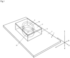
- Fig. 1 through Fig. 3 are diagrams illustrating a first embodiment of a speaker device according to the present invention.
- a speaker device 1 is a device in which a vibration device 3 is brought into contact with one flat surface of a diaphragm 2.
- the speaker device 1 emits vibrations transmitted from the vibration device 3 from the diaphragm 2 as sound.
- the speaker device 1 includes the diaphragm 2, the vibration device 3, a frame body 4, and an elastic body 5.
- the frame body 4 is provided to the diaphragm 2 so as to surround the vibration device 3.
- the elastic body 5 is provided facing the flat surface of the diaphragm 2 with the frame body 4 and the vibration device 3 interposed therebetween.
- the frame body 4 is provided with a gap 32 interposed between itself and the outer circumference of the vibration device 3.
- the elastic body 5 is laid across the frame body 4 and the vibration device 3, and fastened to the frame body 4 and the vibration device 3.
- the frame body 4, the vibration device 3, and the elastic body 5 are thus integrated with each other.
- the vibration device 3 includes a drive shaft 31 with its end portion brought into contact with the diaphragm 2.
- the drive shaft 31 is fixed to the vibration device 3 and integrated with the vibration device 3.
- one vibration device 3 is provided to the diaphragm 2.
- this is not limiting, and a plurality of vibration devices 3 may be provided.
- the drive shaft 31 in a substantially cylindrical shape provided on or near the central axis of vibrations of the vibration device 3 is brought into contact with the diaphragm 2.
- the axial direction of the drive shaft 31 is along the Z direction in the diagrams.
- the end portion of the drive shaft 31 is brought into contact with the flat surface of the diaphragm 2 (the flat surface defined in the X and Y directions) substantially vertically. It is designed such that the vibrations generated in the vibration device 3 are concentrated on the portion brought into contact with the drive shaft 31 in the diaphragm 2. This structure enables the vibration device 3 to efficiently transmit the vibrations, even if they are small, to the diaphragm 2.
- the frame body 4 disposed so as to surround the vibration device 3 and the vibration device 3 are provided so that the surface of the vibration device 3 opposite to the side of the drive shaft 31 brought into contact with the diaphragm 2 is coupled to the frame body 4 with the elastic body 5 interposed therebetween.
- the elastic body 5 operates following the operation of the drive shaft 31.
- the diaphragm 2, the frame body 4, the vibration device 3, and the elastic body 5 are thus integrated with each other. With such a structure, the vibrations generated from the vibration device 3 can be efficiently transmitted to the diaphragm continuously. Thus, sound volume can be secured and clear sound with a wide range can be produced.
- the vibration device 3 In contrast, without such integration of the frame body 4, the vibration device 3, and the elastic body 5, it is concerned that, in the vibration device 3, when the vibration device 3 is in operation, a motion like a pendulum is generated pivoted about the contact portion of the drive shaft 31 with the diaphragm 2 as a fulcrum, and this motion blocks the operation on the driving axle in the Z direction of the drive shaft 31. As a result, the vibrations generated from the vibration device 3 may no longer be efficiently transmitted to the diaphragm continuously.
- the elastic body 5 is provided covering the frame body 4 provided to the diaphragm 2, the gap 32 uniformly disposed on the outer circumference of the vibration device 3, and the vibration device 3.
- the elastic body 5 is provided across all the surfaces in the X direction and the Y direction of the vibration device 3 on the side facing the diaphragm 2 with the frame body 4 interposed therebetween and of the frame body 4.
- the outer circumference of the vibration device 3 is in a substantially cylindrical shape
- the inner circumference of the frame body 4 on the side of the vibration device 3 is in a substantially tubular shape facing the shape of the outer circumference of the vibration device 3.
- the drive shaft 31 of the vibration device 3 is provided in the center of the vibration device 3.
- the gap 32 in the radial direction between the inner circumference of the frame body 4 and the outer circumference of the vibration device 3 is constant entirely in the circumferential direction.
- all the surfaces facing the flat surface of the diaphragm 2 (the side with which the vibration device is brought into contact) (all the surfaces in the X direction and the Y direction) are fastened to the elastic body 5. Provision of such a uniform gap prevents distortion of a later-described urging force due to the elastic body, achieving more efficient transmission of the vibrations generated from the vibration device to the diaphragm.
- the frame body 4 and the vibration device 3 are coupled to each other by being fastened to the elastic body 5 without internal stress (tension or deflection).
- the fastening method is not particularly limited. For example, adhesion by applying an adhesive agent, adhesion with a double-sided tape, melt adhesion between members, and other methods may be adopted.
- all the surfaces facing the flat surface of the diaphragm 2 are fastened to the elastic body 5 by a uniform adhesive force with an adhesive agent or a double-sided tape.
- a later-described urging force due to the elastic body may fail to be sufficiently obtained, or distortion (in the X direction or the Y direction) may be generated in the urging force.
- the elastic body 5 in the state in which the vibration device 3 is not in operation, no stress serving as the urging force operates in the X direction, the Y direction, or the Z direction of the elastic body 5, whereby the vibration device 3 is stable.
- the vibration device 3 when the vibration device 3 is in operation, motions are added to the elastic body 5 in the X direction, the Y direction, and the Z direction, generating an internal stress, and motions serving as tension and deflection to the gap 32 operate on the vibration device 3 in the X direction and the Y direction at a time.
- the internal stress generated in the elastic body 5 is mitigated at the portion of the gap 32, and thus the motion of the vibration device 3 in the directions the elastic body 5 is provided together with the vibration device 3 and the frame body 4 (the X direction and the Y direction) is blocked and stabilized.
- the elastic body 5 operates following the operation in the Z direction ( Fig. 1 or Fig. 3 ) of the drive shaft 31 of the vibrations generated from the vibration device 3, whereby an internal stress is generated on the elastic body 5. Because the elastic body 5 is fastened to the frame body 4 and the vibration device 3 by a uniform adhesive force with entire surface adhesion or the like, a repulsive force to the internal stress is generated, which serves as the urging force to the vibration device 3.
- the vibration device 3 when the vibration device 3 is in operation, the motion linked with and following the operation in the Z direction of the drive shaft 31 of the vibration device 3 is generated, and the internal stress is generated on the elastic body 5.
- the repulsive force to the internal stress in the Z direction ( Fig. 1 or Fig. 3 ) serves as the urging force added to the vibration device 3.
- This urging force prevents the portions of the vibration device 3 brought into contact with the diaphragm 2 from being suspended, whereby the vibrations generated from the vibration device 3 can be efficiently transmitted to the diaphragm 2 continuously.
- the above-described urging force is not displaced in the X direction or the Y direction, and serves as a force in the Z direction that is the vibration direction of the drive shaft 31.
- the vibrations generated from the vibration device 3 can be efficiently transmitted to the diaphragm 2.
- sound volume can be secured and clear sound with a wide range can be produced.
- clear sound with a wide range can be produced.
- the elastic body 5 is made of rubber and shaped into a sheet with a certain thickness. More specifically, the elastic body 5 may be made of rubber and shaped into a sheet with a thickness of about 1 mm to 10 mm, and preferably, made from a material of expandable natural rubber and shaped into a sheet with a thickness of 3 mm, and processed into a shape conforming to the outline of the frame body 4. Furthermore, the elastic body 5 may be made of other materials having similar functions as long as they fall within the scope of the claims.
- the frame body 4 may be preferably made of the material used for the diaphragm 2.
- Examples of the shape preferably include the shapes illustrated in Fig. 1 through Fig. 3 .
- the elastic body 5 when settled, is in a shape of a flat plate sheet that is parallel to the diaphragm 2, and the fastening surfaces of the elastic body 5 to the frame body 4 and the vibration device 3 are parallel to the diaphragm 2.
- the dimension of the frame body 4 in the Z direction is preferably determined so that the surface opposite to the surface on which the drive shaft 31 of the vibration device 3 is provided, which is obtained when the vibration device 3 is settled to the diaphragm 2, is parallel to the diaphragm 2, and flush with the surface opposite to the surface on the side of the diaphragm 2 of the frame body 4, whereby no internal stress is added to the elastic body 5 in the Z direction if the elastic body 5 is provided.
- the planar shape of the frame body 4 is preferably formed into a square with a side dimension that is about twice the planar dimension of the vibration device 3.
- the diaphragm 2 is only required to be a member to which the vibrations from the vibration device 3 are transmitted and capable of emitting the vibrations as sound.
- a hard plate material flat plate
- examples of such a hard flat plate material include wood, wooden material, bamboo, plasterboard, metal, glass, and rigid plastics.
- the diaphragm 2 may be preferably made of wood such as building materials discarded from buildings.
- the diaphragm 2 is made of, for example, a hard flat plate material (wood).
- Hard wood is sufficiently dried wood, and it has reached an equilibrium state at a constant moisture content according to the temperature and humidity in the air.
- the cells in such wood shrink due to sufficient drying.
- the wood discarded from buildings it has been sufficiently dried during the period it was used as part of buildings and it has become old wood. Natural drying over time facilitates shrinkage of the wood. Furthermore, by being exposed to the air or ultraviolet rays, the wood is oxidized and becomes old wood.
- the end portion of the drive shaft 31 of the vibration device 3 is liable to be a simple sound source at the contact point of the contact portion, which concentratedly receives vibrations generated from the vibration device 3, whereby strong vibrations are generated and the vibrations are entirely transmitted to the diaphragm 2 smoothly.
- the diaphragm 2 is preferably made of conifer having a specific gravity in air-dry condition of about 0.3 to 0.65 and formed along the direction of the grain.
- the vibrations are transmitted by fibers of growth rings, amplified by the whole of the diaphragm 2, and emitted as sound. Therefore, the hard portion with low growth in winter is liable to emit high sound, and the soft portion with high growth in summer is liable to emit low sound, whereby vibrations of a mixture of high sound and low sound are liable to be generated.
- the diaphragm 2 made of such wood has appropriate viscosity, and the coefficient of restitution on the surface is lower than that of one made of metal or rigid plastics.
- the vibration device may be used as an amplifier to be in contact with another larger vibration member (a second diaphragm, wall, ceiling, floor, or furniture), and used as a speaker device.
- the whole including the vibration member serves as the speaker device according to the present invention.
- the sound generated from the vibration device 3 is transmitted by bone conduction.
- the material for the vibration member are not limited to hard plate materials and may include flexible materials.
- the material may be textile, paper, plastic sheet, wallpaper, and cloth.
- the shape of the vibration member may be a curtain-like or screen-like shape.
- the diaphragm 2 according to the present invention may be made of such a flexible material, if only it is a member to which the vibrations from the vibration device 3 are transmitted and is capable of emitting the vibrations as sound.
- Fig. 4 and Fig. 5 are diagrams illustrating a second example speaker.
- This speaker device is an example in which the vibration device 3 is settled to the diaphragm 2 with an enlarged area of the end portion of the drive shaft 31 brought into contact with the diaphragm 2.
- the drive shaft 31 has a structure in which a disc-shaped collar portion is provided to a first end of its body in a substantially cylindrical shape. The collar portion is the end portion of the drive shaft 31, and the disc flat surface of the collar portion is brought into contact with the diaphragm 2.
- the structure excluding the drive shaft 31 is the same as that in the embodiment illustrated in Fig. 1 through Fig. 3 .
- a recessed portion may be formed corresponding to the end portion of the drive shaft 31, into which the end portion of the drive shaft 31 is fitted. This structure facilitates alignment in assembly, thus improving workability.
- Fig. 6 and Fig. 7 are diagrams illustrating a third example speaker.
- This speaker device is an example in which the vibration device 3 is settled to the diaphragm 2 with an enlarged area of the end portion of the drive shaft 31 brought into contact with the diaphragm 2, and the frame body 4 is provided with an auxiliary member 41.
- the auxiliary member 41 is a member to readily adjust the dimension so that, in the frame body 4, the surface opposite to the surface on which the drive shaft 31 of the vibration device 3 is provided, which is obtained when the vibration device 3 is settled to the diaphragm 2, is parallel to the diaphragm 2, and flush with the surface opposite to the surface on the side of the diaphragm 2 of the frame body 4.
- the structure excluding the drive shaft 31, the frame body 4, and the auxiliary member 41 is the same as that in the embodiment illustrated in Fig. 1 through Fig. 3 .
- the detailed structure of the drive shaft 31 is the same as that in the second example illustrated in Fig. 4 and Fig. 5 .
- a speaker device In a speaker device according to the present invention, vibrations generated from a vibration device can be efficiently transmitted to a diaphragm, and thus sound volume can be secured and clear sound with a wide range can be produced. Therefore, the speaker device according to the present invention can be widely used as a speaker device for variety of usage, for example, an indoor, outdoor, large-sized, or small-sized speaker.
Landscapes
- Engineering & Computer Science (AREA)
- Physics & Mathematics (AREA)
- Acoustics & Sound (AREA)
- Signal Processing (AREA)
- Health & Medical Sciences (AREA)
- Otolaryngology (AREA)
- Multimedia (AREA)
- Diaphragms For Electromechanical Transducers (AREA)
- Obtaining Desirable Characteristics In Audible-Bandwidth Transducers (AREA)
Claims (2)
- Dispositif de haut-parleur dans lequel un dispositif de vibrations (3) est mis en contact avec une surface plate d'une membrane (2), le dispositif de haut-parleur (1) étant configuré pour émettre des vibrations transmises par le biais du dispositif de vibrations (3) à partir de la membrane (2) en tant que son, le dispositif de haut-parleur (1) comprenant :la membrane (2) ;le dispositif de vibrations (3) ;un corps de cadre (4) prévu directement en contact avec la membrane (2) de manière à entourer le dispositif de vibrations (3) ; etun corps élastique (5) prévu parallèlement à la surface plate de la membrane (2) avec le corps de cadre (4) et le dispositif de vibrations (3) interposés entre ceux-ci, dans lequelle corps de cadre (4) est doté d'un espace (32) interposé entre le corps de cadre (4) et une circonférence extérieure du dispositif de vibrations (3),le corps élastique (5) est une feuille de caoutchouc, qui est posée sur le corps de cadre (4) et le dispositif de vibrations (3), et qui est fixée à toutes les surfaces de contact sur le corps de cadre (4) et le dispositif de vibrations (3),le corps de cadre (4), le dispositif de vibrations (3) et le corps élastique (5) sont intégrés les uns aux autres,la circonférence extérieure du dispositif de vibrations (3) ayant une forme sensiblement cylindrique,la circonférence intérieure du corps de cadre (4) sur le côté du dispositif de vibrations (3) a une forme sensiblement tubulaire faisant face à la forme de la circonférence extérieure du dispositif de vibrations (3),un arbre de commande (31) du dispositif de vibrations (3) est disposé dans un centre du dispositif de vibrations (3), et l'espace dans une direction radiale entre la circonférence intérieure du corps de cadre (4) et la circonférence extérieure du dispositif de vibrations (3) est constant entièrement dans une direction circonférentielle,
etune partie d'extrémité de l'arbre de commande (31) est mise en contact à un point de contact avec la surface plate de la membrane (2) de telle sorte qu'une force de poussée soit générée dans une direction axiale de l'arbre de commande (31) du dispositif de vibrations (3) lorsque le dispositif de vibrations (3) est en fonctionnement, générant ainsi une source sonore simple. - Dispositif de haut-parleur (1) selon la revendication 1, dans lequel le dispositif de haut-parleur (1) comporte un élément de vibration mis en contact avec la membrane (2).
Applications Claiming Priority (1)
| Application Number | Priority Date | Filing Date | Title |
|---|---|---|---|
| PCT/JP2018/017715 WO2019215804A1 (fr) | 2018-05-08 | 2018-05-08 | Appareil de haut-parleur |
Publications (3)
| Publication Number | Publication Date |
|---|---|
| EP3606087A1 EP3606087A1 (fr) | 2020-02-05 |
| EP3606087A4 EP3606087A4 (fr) | 2020-11-04 |
| EP3606087B1 true EP3606087B1 (fr) | 2024-12-18 |
Family
ID=68467344
Family Applications (1)
| Application Number | Title | Priority Date | Filing Date |
|---|---|---|---|
| EP18915783.7A Active EP3606087B1 (fr) | 2018-05-08 | 2018-05-08 | Appareil de haut-parleur |
Country Status (8)
| Country | Link |
|---|---|
| US (1) | US20210409868A1 (fr) |
| EP (1) | EP3606087B1 (fr) |
| JP (1) | JP6630894B1 (fr) |
| CN (1) | CN111869230A (fr) |
| CA (1) | CA3092612C (fr) |
| FI (1) | FI3606087T3 (fr) |
| MY (1) | MY204655A (fr) |
| WO (1) | WO2019215804A1 (fr) |
Families Citing this family (2)
| Publication number | Priority date | Publication date | Assignee | Title |
|---|---|---|---|---|
| JP7269135B2 (ja) * | 2019-08-29 | 2023-05-08 | フォルシアクラリオン・エレクトロニクス株式会社 | 振動出力装置 |
| CN119485082A (zh) * | 2024-09-09 | 2025-02-18 | 天津大学 | 一种振动式地板音箱装置及其应用 |
Citations (1)
| Publication number | Priority date | Publication date | Assignee | Title |
|---|---|---|---|---|
| EP2023656A1 (fr) * | 2006-05-29 | 2009-02-11 | Panasonic Corporation | Excitateur acoustique et haut-parleur l'utilisant |
Family Cites Families (8)
| Publication number | Priority date | Publication date | Assignee | Title |
|---|---|---|---|---|
| JP2004064726A (ja) * | 2002-06-05 | 2004-02-26 | Sanken Kogyo Kk | 薄型フラットスピーカー装置 |
| JP5513083B2 (ja) * | 2009-11-17 | 2014-06-04 | 大和ハウス工業株式会社 | 建築用面板を利用したスピーカー |
| US8325968B2 (en) * | 2009-12-21 | 2012-12-04 | Aac Acoustic Technologies (Shenzhen) Co., Ltd. | Speaker |
| CN109905823B (zh) * | 2014-01-22 | 2020-10-20 | 宁波升亚电子有限公司 | 一种无弹波扬声器及其制造方法 |
| JP2015156605A (ja) | 2014-02-21 | 2015-08-27 | 金平 横濱 | スピーカー装置 |
| JP5713303B1 (ja) * | 2014-04-01 | 2015-05-07 | 金平 横濱 | スピーカー |
| JP2016058936A (ja) * | 2014-09-11 | 2016-04-21 | 金平 横濱 | スピーカー装置 |
| JP2018078410A (ja) * | 2016-11-08 | 2018-05-17 | 株式会社山の加工場ネットワーク | スピーカー装置 |
-
2018
- 2018-05-08 US US16/607,047 patent/US20210409868A1/en not_active Abandoned
- 2018-05-08 FI FIEP18915783.7T patent/FI3606087T3/fi active
- 2018-05-08 CA CA3092612A patent/CA3092612C/fr active Active
- 2018-05-08 MY MYPI2020004538A patent/MY204655A/en unknown
- 2018-05-08 EP EP18915783.7A patent/EP3606087B1/fr active Active
- 2018-05-08 JP JP2019537861A patent/JP6630894B1/ja active Active
- 2018-05-08 WO PCT/JP2018/017715 patent/WO2019215804A1/fr not_active Ceased
- 2018-05-08 CN CN201880091378.3A patent/CN111869230A/zh active Pending
Patent Citations (1)
| Publication number | Priority date | Publication date | Assignee | Title |
|---|---|---|---|---|
| EP2023656A1 (fr) * | 2006-05-29 | 2009-02-11 | Panasonic Corporation | Excitateur acoustique et haut-parleur l'utilisant |
Also Published As
| Publication number | Publication date |
|---|---|
| MY204655A (en) | 2024-09-06 |
| CN111869230A (zh) | 2020-10-30 |
| WO2019215804A1 (fr) | 2019-11-14 |
| JP6630894B1 (ja) | 2020-01-15 |
| CA3092612C (fr) | 2023-02-14 |
| US20210409868A1 (en) | 2021-12-30 |
| EP3606087A4 (fr) | 2020-11-04 |
| JPWO2019215804A1 (ja) | 2020-05-28 |
| FI3606087T3 (fi) | 2025-03-26 |
| CA3092612A1 (fr) | 2019-11-14 |
| EP3606087A1 (fr) | 2020-02-05 |
Similar Documents
| Publication | Publication Date | Title |
|---|---|---|
| US8247930B2 (en) | Acoustic exciter and speaker using it | |
| US20140270279A1 (en) | Acoustic transducers with releasable diaphram | |
| EP2068586B1 (fr) | Appareil haut-parleur et son procédé de commande | |
| CN100484260C (zh) | 具有声板和电激励器的扬声器 | |
| EP3606087B1 (fr) | Appareil de haut-parleur | |
| CN103650531A (zh) | 具有力抵消配置的扬声器 | |
| US8494208B2 (en) | Inertial vibration exciter | |
| US7636447B2 (en) | Acoustic bracket system | |
| US20160360313A1 (en) | Distributed mode louspeaker damping oscillations within exciter feet | |
| CN1012316B (zh) | 宽带扬声器 | |
| JP2003153374A (ja) | 向上したオーディオ性能を有するフラットパネルサウンドラジエータ | |
| EP1450578A2 (fr) | Transducteur électroacoustique | |
| CZ20031501A3 (cs) | Reproduktor | |
| KR102115387B1 (ko) | 무빙 자기회로 타입 복합 스피커 | |
| KR102115383B1 (ko) | 진동 패널 장착용 익사이터 | |
| US8240426B2 (en) | Three dimensional acoustic passive radiating | |
| JP2018078410A (ja) | スピーカー装置 | |
| JP2019221003A (ja) | スピーカー装置 | |
| JP2020096213A (ja) | 音響用の加振装置および前記加振装置を使用した発音装置 | |
| JP3924777B2 (ja) | フラットスピーカ | |
| CN109362007A (zh) | 扬声器装置 | |
| US1859921A (en) | Acoustic device | |
| JPH0563236B2 (fr) | ||
| JP3175938B2 (ja) | スピーカ | |
| GB2349034A (en) | Supporting surround for active panel of distributed mode speaker |
Legal Events
| Date | Code | Title | Description |
|---|---|---|---|
| STAA | Information on the status of an ep patent application or granted ep patent |
Free format text: STATUS: UNKNOWN |
|
| STAA | Information on the status of an ep patent application or granted ep patent |
Free format text: STATUS: THE INTERNATIONAL PUBLICATION HAS BEEN MADE |
|
| PUAI | Public reference made under article 153(3) epc to a published international application that has entered the european phase |
Free format text: ORIGINAL CODE: 0009012 |
|
| STAA | Information on the status of an ep patent application or granted ep patent |
Free format text: STATUS: REQUEST FOR EXAMINATION WAS MADE |
|
| 17P | Request for examination filed |
Effective date: 20191029 |
|
| AK | Designated contracting states |
Kind code of ref document: A1 Designated state(s): AL AT BE BG CH CY CZ DE DK EE ES FI FR GB GR HR HU IE IS IT LI LT LU LV MC MK MT NL NO PL PT RO RS SE SI SK SM TR |
|
| AX | Request for extension of the european patent |
Extension state: BA ME |
|
| REG | Reference to a national code |
Free format text: PREVIOUS MAIN CLASS: H04R0001000000 Ref country code: DE Ref legal event code: R079 Ref document number: 602018077832 Country of ref document: DE Free format text: PREVIOUS MAIN CLASS: H04R0001000000 Ipc: H04R0007040000 |
|
| A4 | Supplementary search report drawn up and despatched |
Effective date: 20201007 |
|
| RIC1 | Information provided on ipc code assigned before grant |
Ipc: H04R 9/06 20060101ALI20201001BHEP Ipc: H04R 7/04 20060101AFI20201001BHEP |
|
| STAA | Information on the status of an ep patent application or granted ep patent |
Free format text: STATUS: EXAMINATION IS IN PROGRESS |
|
| 17Q | First examination report despatched |
Effective date: 20210602 |
|
| DAV | Request for validation of the european patent (deleted) | ||
| DAX | Request for extension of the european patent (deleted) | ||
| GRAP | Despatch of communication of intention to grant a patent |
Free format text: ORIGINAL CODE: EPIDOSNIGR1 |
|
| STAA | Information on the status of an ep patent application or granted ep patent |
Free format text: STATUS: GRANT OF PATENT IS INTENDED |
|
| INTG | Intention to grant announced |
Effective date: 20240704 |
|
| GRAS | Grant fee paid |
Free format text: ORIGINAL CODE: EPIDOSNIGR3 |
|
| GRAA | (expected) grant |
Free format text: ORIGINAL CODE: 0009210 |
|
| STAA | Information on the status of an ep patent application or granted ep patent |
Free format text: STATUS: THE PATENT HAS BEEN GRANTED |
|
| AK | Designated contracting states |
Kind code of ref document: B1 Designated state(s): AL AT BE BG CH CY CZ DE DK EE ES FI FR GB GR HR HU IE IS IT LI LT LU LV MC MK MT NL NO PL PT RO RS SE SI SK SM TR |
|
| REG | Reference to a national code |
Ref country code: CH Ref legal event code: EP |
|
| REG | Reference to a national code |
Ref country code: DE Ref legal event code: R096 Ref document number: 602018077832 Country of ref document: DE |
|
| REG | Reference to a national code |
Ref country code: IE Ref legal event code: FG4D |
|
| REG | Reference to a national code |
Ref country code: FI Ref legal event code: FGE |
|
| REG | Reference to a national code |
Ref country code: LT Ref legal event code: MG9D |
|
| PG25 | Lapsed in a contracting state [announced via postgrant information from national office to epo] |
Ref country code: HR Free format text: LAPSE BECAUSE OF FAILURE TO SUBMIT A TRANSLATION OF THE DESCRIPTION OR TO PAY THE FEE WITHIN THE PRESCRIBED TIME-LIMIT Effective date: 20241218 |
|
| PG25 | Lapsed in a contracting state [announced via postgrant information from national office to epo] |
Ref country code: BG Free format text: LAPSE BECAUSE OF FAILURE TO SUBMIT A TRANSLATION OF THE DESCRIPTION OR TO PAY THE FEE WITHIN THE PRESCRIBED TIME-LIMIT Effective date: 20241218 |
|
| PG25 | Lapsed in a contracting state [announced via postgrant information from national office to epo] |
Ref country code: NO Free format text: LAPSE BECAUSE OF FAILURE TO SUBMIT A TRANSLATION OF THE DESCRIPTION OR TO PAY THE FEE WITHIN THE PRESCRIBED TIME-LIMIT Effective date: 20250318 |
|
| REG | Reference to a national code |
Ref country code: NL Ref legal event code: MP Effective date: 20241218 |
|
| PG25 | Lapsed in a contracting state [announced via postgrant information from national office to epo] |
Ref country code: LV Free format text: LAPSE BECAUSE OF FAILURE TO SUBMIT A TRANSLATION OF THE DESCRIPTION OR TO PAY THE FEE WITHIN THE PRESCRIBED TIME-LIMIT Effective date: 20241218 Ref country code: GR Free format text: LAPSE BECAUSE OF FAILURE TO SUBMIT A TRANSLATION OF THE DESCRIPTION OR TO PAY THE FEE WITHIN THE PRESCRIBED TIME-LIMIT Effective date: 20250319 |
|
| PG25 | Lapsed in a contracting state [announced via postgrant information from national office to epo] |
Ref country code: RS Free format text: LAPSE BECAUSE OF FAILURE TO SUBMIT A TRANSLATION OF THE DESCRIPTION OR TO PAY THE FEE WITHIN THE PRESCRIBED TIME-LIMIT Effective date: 20250318 |
|
| PG25 | Lapsed in a contracting state [announced via postgrant information from national office to epo] |
Ref country code: NL Free format text: LAPSE BECAUSE OF FAILURE TO SUBMIT A TRANSLATION OF THE DESCRIPTION OR TO PAY THE FEE WITHIN THE PRESCRIBED TIME-LIMIT Effective date: 20241218 |
|
| REG | Reference to a national code |
Ref country code: AT Ref legal event code: MK05 Ref document number: 1753234 Country of ref document: AT Kind code of ref document: T Effective date: 20241218 |
|
| PG25 | Lapsed in a contracting state [announced via postgrant information from national office to epo] |
Ref country code: SM Free format text: LAPSE BECAUSE OF FAILURE TO SUBMIT A TRANSLATION OF THE DESCRIPTION OR TO PAY THE FEE WITHIN THE PRESCRIBED TIME-LIMIT Effective date: 20241218 |
|
| PGFP | Annual fee paid to national office [announced via postgrant information from national office to epo] |
Ref country code: FI Payment date: 20250520 Year of fee payment: 8 |
|
| PG25 | Lapsed in a contracting state [announced via postgrant information from national office to epo] |
Ref country code: PL Free format text: LAPSE BECAUSE OF FAILURE TO SUBMIT A TRANSLATION OF THE DESCRIPTION OR TO PAY THE FEE WITHIN THE PRESCRIBED TIME-LIMIT Effective date: 20241218 |
|
| PGFP | Annual fee paid to national office [announced via postgrant information from national office to epo] |
Ref country code: DE Payment date: 20250529 Year of fee payment: 8 |
|
| PG25 | Lapsed in a contracting state [announced via postgrant information from national office to epo] |
Ref country code: ES Free format text: LAPSE BECAUSE OF FAILURE TO SUBMIT A TRANSLATION OF THE DESCRIPTION OR TO PAY THE FEE WITHIN THE PRESCRIBED TIME-LIMIT Effective date: 20241218 |
|
| PGFP | Annual fee paid to national office [announced via postgrant information from national office to epo] |
Ref country code: GB Payment date: 20250522 Year of fee payment: 8 |
|
| PG25 | Lapsed in a contracting state [announced via postgrant information from national office to epo] |
Ref country code: IS Free format text: LAPSE BECAUSE OF FAILURE TO SUBMIT A TRANSLATION OF THE DESCRIPTION OR TO PAY THE FEE WITHIN THE PRESCRIBED TIME-LIMIT Effective date: 20250418 |
|
| PGFP | Annual fee paid to national office [announced via postgrant information from national office to epo] |
Ref country code: BE Payment date: 20250520 Year of fee payment: 8 Ref country code: IT Payment date: 20250530 Year of fee payment: 8 |
|
| PG25 | Lapsed in a contracting state [announced via postgrant information from national office to epo] |
Ref country code: PT Free format text: LAPSE BECAUSE OF FAILURE TO SUBMIT A TRANSLATION OF THE DESCRIPTION OR TO PAY THE FEE WITHIN THE PRESCRIBED TIME-LIMIT Effective date: 20250421 |
|
| PG25 | Lapsed in a contracting state [announced via postgrant information from national office to epo] |
Ref country code: EE Free format text: LAPSE BECAUSE OF FAILURE TO SUBMIT A TRANSLATION OF THE DESCRIPTION OR TO PAY THE FEE WITHIN THE PRESCRIBED TIME-LIMIT Effective date: 20241218 |
|
| PGFP | Annual fee paid to national office [announced via postgrant information from national office to epo] |
Ref country code: FR Payment date: 20250523 Year of fee payment: 8 |
|
| PG25 | Lapsed in a contracting state [announced via postgrant information from national office to epo] |
Ref country code: RO Free format text: LAPSE BECAUSE OF FAILURE TO SUBMIT A TRANSLATION OF THE DESCRIPTION OR TO PAY THE FEE WITHIN THE PRESCRIBED TIME-LIMIT Effective date: 20241218 Ref country code: AT Free format text: LAPSE BECAUSE OF FAILURE TO SUBMIT A TRANSLATION OF THE DESCRIPTION OR TO PAY THE FEE WITHIN THE PRESCRIBED TIME-LIMIT Effective date: 20241218 |
|
| PG25 | Lapsed in a contracting state [announced via postgrant information from national office to epo] |
Ref country code: SK Free format text: LAPSE BECAUSE OF FAILURE TO SUBMIT A TRANSLATION OF THE DESCRIPTION OR TO PAY THE FEE WITHIN THE PRESCRIBED TIME-LIMIT Effective date: 20241218 |
|
| PG25 | Lapsed in a contracting state [announced via postgrant information from national office to epo] |
Ref country code: CZ Free format text: LAPSE BECAUSE OF FAILURE TO SUBMIT A TRANSLATION OF THE DESCRIPTION OR TO PAY THE FEE WITHIN THE PRESCRIBED TIME-LIMIT Effective date: 20241218 |
|
| PG25 | Lapsed in a contracting state [announced via postgrant information from national office to epo] |
Ref country code: SE Free format text: LAPSE BECAUSE OF FAILURE TO SUBMIT A TRANSLATION OF THE DESCRIPTION OR TO PAY THE FEE WITHIN THE PRESCRIBED TIME-LIMIT Effective date: 20241218 |
|
| REG | Reference to a national code |
Ref country code: DE Ref legal event code: R097 Ref document number: 602018077832 Country of ref document: DE |
|
| PG25 | Lapsed in a contracting state [announced via postgrant information from national office to epo] |
Ref country code: DK Free format text: LAPSE BECAUSE OF FAILURE TO SUBMIT A TRANSLATION OF THE DESCRIPTION OR TO PAY THE FEE WITHIN THE PRESCRIBED TIME-LIMIT Effective date: 20241218 |
|
| PLBE | No opposition filed within time limit |
Free format text: ORIGINAL CODE: 0009261 |
|
| STAA | Information on the status of an ep patent application or granted ep patent |
Free format text: STATUS: NO OPPOSITION FILED WITHIN TIME LIMIT |
|
| REG | Reference to a national code |
Ref country code: CH Ref legal event code: L10 Free format text: ST27 STATUS EVENT CODE: U-0-0-L10-L00 (AS PROVIDED BY THE NATIONAL OFFICE) Effective date: 20251029 |
|
| 26N | No opposition filed |
Effective date: 20250919 |
|
| REG | Reference to a national code |
Ref country code: CH Ref legal event code: H13 Free format text: ST27 STATUS EVENT CODE: U-0-0-H10-H13 (AS PROVIDED BY THE NATIONAL OFFICE) Effective date: 20251223 |
|
| PG25 | Lapsed in a contracting state [announced via postgrant information from national office to epo] |
Ref country code: LU Free format text: LAPSE BECAUSE OF NON-PAYMENT OF DUE FEES Effective date: 20250508 |
|
| PG25 | Lapsed in a contracting state [announced via postgrant information from national office to epo] |
Ref country code: CH Free format text: LAPSE BECAUSE OF NON-PAYMENT OF DUE FEES Effective date: 20250531 |
|
| PG25 | Lapsed in a contracting state [announced via postgrant information from national office to epo] |
Ref country code: MC Free format text: LAPSE BECAUSE OF FAILURE TO SUBMIT A TRANSLATION OF THE DESCRIPTION OR TO PAY THE FEE WITHIN THE PRESCRIBED TIME-LIMIT Effective date: 20241218 |
|
| PG25 | Lapsed in a contracting state [announced via postgrant information from national office to epo] |
Ref country code: IE Free format text: LAPSE BECAUSE OF NON-PAYMENT OF DUE FEES Effective date: 20250508 |