EP3606284A1 - Procédé et dispositif de transmission inductive d'énergie - Google Patents
Procédé et dispositif de transmission inductive d'énergie Download PDFInfo
- Publication number
- EP3606284A1 EP3606284A1 EP19186440.4A EP19186440A EP3606284A1 EP 3606284 A1 EP3606284 A1 EP 3606284A1 EP 19186440 A EP19186440 A EP 19186440A EP 3606284 A1 EP3606284 A1 EP 3606284A1
- Authority
- EP
- European Patent Office
- Prior art keywords
- coil
- current
- transmitter
- saturation
- ferrites
- Prior art date
- Legal status (The legal status is an assumption and is not a legal conclusion. Google has not performed a legal analysis and makes no representation as to the accuracy of the status listed.)
- Granted
Links
Images


Classifications
-
- H—ELECTRICITY
- H05—ELECTRIC TECHNIQUES NOT OTHERWISE PROVIDED FOR
- H05B—ELECTRIC HEATING; ELECTRIC LIGHT SOURCES NOT OTHERWISE PROVIDED FOR; CIRCUIT ARRANGEMENTS FOR ELECTRIC LIGHT SOURCES, IN GENERAL
- H05B6/00—Heating by electric, magnetic or electromagnetic fields
- H05B6/02—Induction heating
- H05B6/06—Control, e.g. of temperature, of power
- H05B6/062—Control, e.g. of temperature, of power for cooking plates or the like
-
- H—ELECTRICITY
- H02—GENERATION; CONVERSION OR DISTRIBUTION OF ELECTRIC POWER
- H02J—ELECTRIC POWER NETWORKS; CIRCUIT ARRANGEMENTS OR SYSTEMS FOR SUPPLYING OR DISTRIBUTING ELECTRIC POWER; SYSTEMS FOR STORING ELECTRIC ENERGY
- H02J50/00—Circuit arrangements or systems for wireless supply or distribution of electric power
- H02J50/10—Circuit arrangements or systems for wireless supply or distribution of electric power using inductive coupling
-
- H—ELECTRICITY
- H01—ELECTRIC ELEMENTS
- H01F—MAGNETS; INDUCTANCES; TRANSFORMERS; SELECTION OF MATERIALS FOR THEIR MAGNETIC PROPERTIES
- H01F1/00—Magnets or magnetic bodies characterised by the magnetic materials therefor; Selection of materials for their magnetic properties
- H01F1/01—Magnets or magnetic bodies characterised by the magnetic materials therefor; Selection of materials for their magnetic properties of inorganic materials
- H01F1/03—Magnets or magnetic bodies characterised by the magnetic materials therefor; Selection of materials for their magnetic properties of inorganic materials characterised by their coercivity
- H01F1/0302—Magnets or magnetic bodies characterised by the magnetic materials therefor; Selection of materials for their magnetic properties of inorganic materials characterised by their coercivity characterised by unspecified or heterogeneous hardness or specially adapted for magnetic hardness transitions
- H01F1/0311—Compounds
- H01F1/0313—Oxidic compounds
- H01F1/0315—Ferrites
-
- H—ELECTRICITY
- H01—ELECTRIC ELEMENTS
- H01F—MAGNETS; INDUCTANCES; TRANSFORMERS; SELECTION OF MATERIALS FOR THEIR MAGNETIC PROPERTIES
- H01F38/00—Adaptations of transformers or inductances for specific applications or functions
- H01F38/14—Inductive couplings
-
- H—ELECTRICITY
- H02—GENERATION; CONVERSION OR DISTRIBUTION OF ELECTRIC POWER
- H02J—ELECTRIC POWER NETWORKS; CIRCUIT ARRANGEMENTS OR SYSTEMS FOR SUPPLYING OR DISTRIBUTING ELECTRIC POWER; SYSTEMS FOR STORING ELECTRIC ENERGY
- H02J50/00—Circuit arrangements or systems for wireless supply or distribution of electric power
- H02J50/005—Mechanical details of housing or structure aiming to accommodate the power transfer means, e.g. mechanical integration of coils, antennas or transducers into emitting or receiving devices
-
- H—ELECTRICITY
- H02—GENERATION; CONVERSION OR DISTRIBUTION OF ELECTRIC POWER
- H02J—ELECTRIC POWER NETWORKS; CIRCUIT ARRANGEMENTS OR SYSTEMS FOR SUPPLYING OR DISTRIBUTING ELECTRIC POWER; SYSTEMS FOR STORING ELECTRIC ENERGY
- H02J50/00—Circuit arrangements or systems for wireless supply or distribution of electric power
- H02J50/10—Circuit arrangements or systems for wireless supply or distribution of electric power using inductive coupling
- H02J50/12—Circuit arrangements or systems for wireless supply or distribution of electric power using inductive coupling of the resonant type
-
- H—ELECTRICITY
- H02—GENERATION; CONVERSION OR DISTRIBUTION OF ELECTRIC POWER
- H02J—ELECTRIC POWER NETWORKS; CIRCUIT ARRANGEMENTS OR SYSTEMS FOR SUPPLYING OR DISTRIBUTING ELECTRIC POWER; SYSTEMS FOR STORING ELECTRIC ENERGY
- H02J50/00—Circuit arrangements or systems for wireless supply or distribution of electric power
- H02J50/70—Circuit arrangements or systems for wireless supply or distribution of electric power involving the reduction of electric, magnetic or electromagnetic leakage fields
-
- H—ELECTRICITY
- H04—ELECTRIC COMMUNICATION TECHNIQUE
- H04B—TRANSMISSION
- H04B5/00—Near-field transmission systems, e.g. inductive or capacitive transmission systems
- H04B5/70—Near-field transmission systems, e.g. inductive or capacitive transmission systems specially adapted for specific purposes
- H04B5/79—Near-field transmission systems, e.g. inductive or capacitive transmission systems specially adapted for specific purposes for data transfer in combination with power transfer
-
- H—ELECTRICITY
- H05—ELECTRIC TECHNIQUES NOT OTHERWISE PROVIDED FOR
- H05B—ELECTRIC HEATING; ELECTRIC LIGHT SOURCES NOT OTHERWISE PROVIDED FOR; CIRCUIT ARRANGEMENTS FOR ELECTRIC LIGHT SOURCES, IN GENERAL
- H05B6/00—Heating by electric, magnetic or electromagnetic fields
- H05B6/02—Induction heating
- H05B6/06—Control, e.g. of temperature, of power
-
- H—ELECTRICITY
- H05—ELECTRIC TECHNIQUES NOT OTHERWISE PROVIDED FOR
- H05B—ELECTRIC HEATING; ELECTRIC LIGHT SOURCES NOT OTHERWISE PROVIDED FOR; CIRCUIT ARRANGEMENTS FOR ELECTRIC LIGHT SOURCES, IN GENERAL
- H05B6/00—Heating by electric, magnetic or electromagnetic fields
- H05B6/02—Induction heating
- H05B6/10—Induction heating apparatus, other than furnaces, for specific applications
- H05B6/12—Cooking devices
- H05B6/1209—Cooking devices induction cooking plates or the like and devices to be used in combination with them
- H05B6/1236—Cooking devices induction cooking plates or the like and devices to be used in combination with them adapted to induce current in a coil to supply power to a device and electrical heating devices powered in this way
-
- H—ELECTRICITY
- H05—ELECTRIC TECHNIQUES NOT OTHERWISE PROVIDED FOR
- H05B—ELECTRIC HEATING; ELECTRIC LIGHT SOURCES NOT OTHERWISE PROVIDED FOR; CIRCUIT ARRANGEMENTS FOR ELECTRIC LIGHT SOURCES, IN GENERAL
- H05B6/00—Heating by electric, magnetic or electromagnetic fields
- H05B6/02—Induction heating
- H05B6/10—Induction heating apparatus, other than furnaces, for specific applications
- H05B6/12—Cooking devices
- H05B6/1209—Cooking devices induction cooking plates or the like and devices to be used in combination with them
- H05B6/1245—Cooking devices induction cooking plates or the like and devices to be used in combination with them with special coil arrangements
- H05B6/1254—Cooking devices induction cooking plates or the like and devices to be used in combination with them with special coil arrangements using conductive pieces to direct the induced magnetic field
-
- Y—GENERAL TAGGING OF NEW TECHNOLOGICAL DEVELOPMENTS; GENERAL TAGGING OF CROSS-SECTIONAL TECHNOLOGIES SPANNING OVER SEVERAL SECTIONS OF THE IPC; TECHNICAL SUBJECTS COVERED BY FORMER USPC CROSS-REFERENCE ART COLLECTIONS [XRACs] AND DIGESTS
- Y02—TECHNOLOGIES OR APPLICATIONS FOR MITIGATION OR ADAPTATION AGAINST CLIMATE CHANGE
- Y02B—CLIMATE CHANGE MITIGATION TECHNOLOGIES RELATED TO BUILDINGS, e.g. HOUSING, HOUSE APPLIANCES OR RELATED END-USER APPLICATIONS
- Y02B40/00—Technologies aiming at improving the efficiency of home appliances, e.g. induction cooking or efficient technologies for refrigerators, freezers or dish washers
Definitions
- the invention relates to a method for inductive energy transmission between a transmitter coil and a receiver coil and a device with which this method can be carried out.
- Inductive energy transmission is becoming increasingly important in the field of technology and is, for example, from the EP 2798911 B1 known.
- WPC consortium here, which is working on a manufacturer-independent standard for the wireless energy supply of kitchen appliances.
- the invention has for its object to provide a method mentioned at the outset and a device suitable for carrying it out, with which problems of the prior art can be solved and in particular it is possible to achieve inductive energy transfer as well as possible, in particular also when using a Induction hob as a device for energy transmission.
- the method uses a transmitter coil and a receiver coil to transmit energy inductively. This is advantageously done by means of inductive resonance transmitters.
- the transmitter coil is part of a transmitter resonant circuit and the receiver coil is part of a receiver resonant circuit. Both resonant circuits preferably also have appropriately dimensioned capacitors or capacitors.
- the energy is transmitted inductively from the transmitter resonant circuit to the receiver resonant circuit. This can be preferred according to the standard developed by the WPC consortium, but it does not have to be.
- the magnetic field in the transmitter coil and / or in the receiver coil is guided by ferrites, the ferrites being arranged on the side facing away from the opposite coil.
- ferrites being arranged on the side facing away from the opposite coil.
- metal parts are arranged on the transmitter coil and / or on the receiver coil on a side facing away from the respective counter coil, advantageously as flat metal parts.
- These can be, for example, carrying devices or shielding devices for the respective coil.
- this can preferably be a large-area support plate made of aluminum, on which the at least one transmitter coil is arranged. It is used to mechanically hold the transmitter coil or an induction heating coil and to shield components and assemblies arranged underneath against magnetic fields.
- the current through the transformer coil is monitored. It is regulated or limited in such a way that the ferrites are in the region of onset of saturation or magnetic fluxes induced in the ferrites reach a possible maximum, but if possible no higher current flows through the transmitter coil. This possible maximum then corresponds to saturation. Saturation can occur in the transmitter and / or in the receiver coil. So-called saturation induction of ferrites also decreases with increasing temperature, so it is also temperature-dependent. This means that the saturation in the ferrites occurs faster or with lower currents the warmer they become. When the ferrites are cold, a higher current can be used through the transmitter coil and thus more energy can be transferred. This applies in particular if a controller regulates the point of application of saturation.
- the current through the transformer coil is regulated or limited in such a way that it is at most 5% to 10% above the saturation current at which the said saturation occurs in the ferrites.
- the current through the transformer coil can therefore be somewhat larger, but not much, advantageously only 5% to 10% larger.
- the current through the transformer coil is particularly advantageously even limited to a maximum of 2% above the saturation current, so that the method works almost at the saturation limit.
- the transmitter coil is an induction heating coil of the induction hob.
- the method is particularly advantageously carried out using only a single induction heating coil, these induction heating coils and in particular their power control being specially designed for this purpose.
- the transmitter coil and the transmitter resonant circuit are arranged under a table top, which can serve as a conventional table top as furniture in a household.
- a table top advantageously consisting of wood, stone or other non-magnetic and non-metallic materials, can have a maximum thickness of 60 mm.
- a thickness is advantageously in the range between 5 mm and 20 mm or even 40 mm.
- the device in the sense of this invention is at least also a hob, since the induction heating coil can also be used for cooking.
- a separate base for a cooking vessel can possibly be placed on the table top due to heat problems, but this is not a problem in itself.
- the table top mentioned replaces another hob, which usually consists of glass ceramic.
- Such an induction hob with a table top and at least one induction heating coil underneath can then be made considerably larger than a conventional induction hob.
- the at least one induction heating coil can also be arranged movably underneath so that it can be brought to different positions. The person skilled in the art knows how to implement this in detail from the prior art and need not be explained in more detail here.
- a flat metal sheet is arranged on the transmitter coil on a side facing away from the receiver coil as the aforementioned metal part.
- This flat metal sheet has an area which is at least 70% of the area of the transmitter coil, advantageously at least as large as this transmitter coil. It can serve to give strength to the transformer coil and, above all, to ensure shielding from below.
- a distance between the metal sheet and the transmitter coil can be a maximum of 50 mm, advantageously a maximum of 10 mm to 20 mm. This is related to coil turns of the transmitter coil.
- the flat metal sheet can have openings and openings which allow the transmitter coils and cable feedthroughs to be latched or fixed in place or allow cooling.
- An electrically highly conductive metal with a high aluminum or copper content is preferably used for shielding.
- the ferrites are arranged between the metal sheet and the transmission coil.
- Their thickness is usually in the range between 4 mm and 10 mm, so that the aforementioned advantageous spacing conditions can also be met.
- the ferrites mentioned are advantageously elongated and flat. Their width can be twice to ten times the thickness. Their length can be three to ten times their width.
- the ferrites are preferably arranged on the transmitter coil in such a way that they point in their central region, in particular to a geometric center. Between two and ten ferrites can be provided. They are advantageously identical, but this is not mandatory.
- the first derivative of an envelope curve of the current through the transmitter coil can be calculated or ascertained.
- the envelope curve is understood to be the course of the positive peak values of the current through the transmitter coil.
- This curve can be determined, for example, by means of a sliding peak value detector, so that both the increase in the peak value when the mains voltage rises and the decrease in the peak value when the mains voltage falls.
- This first derivative is smoothed by two low-pass filters that have different time constants.
- a time constant of the second low pass is five to twenty times a time constant of the first low pass, in particular approximately ten times. It can preferably be provided that the time constant of the first low pass corresponds to 1.0 times to five times the period of the current through the transmitter coil. It can particularly preferably correspond to twice the period of the current through the transformer coil.
- Saturation of the ferrites basically occurs with large currents, i.e. it preferably occurs around the maximum of a sinusoidal mains voltage. With 50 Hz networks the maximum is 5.0 ms after the zero crossing, with 60 Hz networks already with 4.17 msec. With an ideal linear load, the first derivative of the current falls according to a cosine function from +1 to -1 of a maximum value; in reality, a behavior deviating from the cosine can occur, in which the first derivative nevertheless decreases continuously in the course of the network half-wave.
- the area around the zero crossings is preferably excluded from the analysis, since saturation occurs first at high voltages, and adjustment processes and non-linearities at small current values can also be a cause for a brief rise in the first derivative. This advantageously results in the aforementioned 2.5 ms.
- the onset of saturation of the ferrites is recognized when the signal after the first low pass breaks through the signal after the second low pass and remains longer for at least 0.2 ms.
- the signal advantageously not only remains larger for at least 0.2 ms, but even 0.5 ms.
- the onset of saturation of the ferrites can be recognized if there is a change in a time window from 2.5 ms to 5 ms after a zero crossing of the mains voltage
- Low pass smoothed first derivative or the moving average of the first derivative of the envelope curve of the current behaves approximately constant or increasing. It can change a maximum of 10% upwards or downwards, preferably by a maximum of 7%.
- the value of the first derivative should not have decreased over a period of at least 0.3 ms, preferably from 0.5 ms to 1 ms, in particular a limit value can be an increase of 10% or 7%.
- an onset of saturation is recognized when the first derivative of the enveloping curve behaves in a quasi-constant or only slightly increasing manner in the time window mentioned.
- the second derivative of the envelope curve of the current is also formed by the transmitter coil.
- An onset of saturation is detected if the second derivative at least occurs in the time window between 2.5 ms and 5 ms after the zero crossing of the enveloping curve of the current Is 1.0 A / ms 2 . In this case, the extent to which the first derivative rises, so to speak, is monitored.
- a reference curve for the envelope curve of the current through the transmitter coil can be recorded in a preceding step. This can take place when 50% of the maximum transferable energy is transmitted, namely at most 50% or even exactly 50%. In any case, it takes place in a state in which the saturation is still far away.
- its envelope curve is compared with the reference curve.
- the two curves are advantageously standardized or matched to one another for comparability.
- An onset of saturation is recognized when the envelope curve of the current through the transmitter coil is at least 10%, preferably at least 20%, larger than the reference curve mentioned.
- the saturation is preferably detected when the enveloping curve is at least 20% larger than the reference curve or exceeds it accordingly.
- an onset saturation is recognized when the first derivative of the current through the transmitter coil occurs in a time window between a tenth and a quarter of the period of the current through the transmitter coil during a falling range or briefly rises again in a falling area.
- This increase advantageously takes place for at least 1 ⁇ s and / or at least 10% of the signal level at this point in time. Under certain circumstances, the increase can only be at least 5%.
- the same methods can also be used to evaluate the currents supplied in the intermediate circuit, see the current i DC in Fig.1 , or on the mains side in front of the rectifier, see the current i AC there .
- the device therefore also has means for monitoring or determining the current through the transmitter coil. Furthermore, it has means for determining the first and possibly also the second derivative of this current. In addition, it has the ferrites on the transmitter coil and underneath a support plate as a metal part.
- the device is advantageously an induction hob with a plurality of induction heating coils, at least one of which is designed, including the control, to carry out the aforementioned method. It is explained in detail below.
- FIG. 1 A device 11 according to the invention is shown, with which the method according to the invention can be carried out and on the basis of which it is described below.
- the device 11 is advantageously an induction hob, as is also known, for example, from the DE 10 2012 219 040 A1 evident.
- the device 11 has a transmitter resonant circuit 13, on which there is a receiver resonant circuit 23, advantageously placed on a hob plate, not shown. These two are coupled via a magnetic field 20 or an inductive energy transfer takes place by means of an inductive resonance transformer.
- the transformer resonant circuit 13 has a transformer coil 15, which is an induction heating coil here. It is advantageously wound from HF coil wire in a spiral. Below the transmission coil 15, ferrites 16 are arranged, in rod form and distributed in the radial direction. There can be six to ten ferrites 16. They are advantageously attached, for example glued, to the underside of the transmitter coil 15. Alternatively, they can be held in a plastic holder. This is known from the prior art for the construction of induction hobs or induction heating coils. The transformer resonant circuit 13 actually still includes the two transformer capacitors 21a and 21b, which are shown on the far right in the circuit diagram.
- the transmitter coil 15 should rest on a flat support plate 18. This is advantageously made of aluminum, it is important that it has low electrical resistance. Alternative materials are copper or possibly a silver alloy.
- the support plate 18, which is also known from the aforementioned publication, on the one hand has a support function for the transmitter coil 15, possibly also for further induction heating coils of the induction hob in the form of the device 11. Furthermore, the support plate 18 shields the underlying electronic and electrical components the magnetic field of the coils arranged thereon. Finally, the support plate 18 can also have a heat-conducting function and thus a cooling function and can be provided with openings or cutouts for fastening or for cable bushings.
- the receiver coil 25 of the receiver resonant circuit 23 is provided above the transmitter coil 15. It is advantageously placed in a flat housing or as a flat device on a cooktop directly above the transformer coil 15.
- the cooktop is not shown here, but is easy to imagine. Instead of a normal cooktop, which usually consists of glass ceramic, it can also be a table top or other storage top with a aforementioned thickness and consisting of the aforementioned materials.
- the transmitter coil 15 can also be used for cooking as with a normal induction heating coil with inductive heating of a cooking vessel placed above it. Inductive energy transfer can also take place in a special operating method.
- the receiver coil 25 can be designed similarly to the transmitter coil 15, in particular approximately the same size or area and shape.
- Ferrites 26 are also arranged and fastened on their upper side as in the case of the transmitter coil 15. Shielding is also conceivable at the top of the receiver, but is not mandatory there.
- the receiver resonant circuit 23 also has a receiver capacitor 29 and a load 28 to which the inductive energy is ultimately to be transmitted or which is to be supplied with energy.
- This load 28 can, for example, as a kitchen device in the form of a blender, kettle or the like. are present, so to speak be placed on the cover above the transmission coil 15 and the so-called wirelessly supplied with energy by induction. Since the load 28 is to function essentially like any other electrical consumer, corresponding to a small electrical appliance or an electrical kitchen appliance.
- the transmitter resonant circuit 13 and the receiver resonant circuit 23 are to be designed thereon, furthermore a control of the transmitter coil 15 is necessary in a corresponding way with a frequency of 50 Hz or 60 Hz.
- the envelope curve of the transformer current which is explained in more detail below, corresponds to this frequency of 50 Hz or 60 Hz.
- the transformer resonant circuit 13 has a first transformer capacitor 21a at the bottom right and a second transformer capacitor 21b above it.
- a tap can be provided for detecting the transmitter current i HF as a current through the transmitter coil.
- two transistors 31a and 31b are provided for driving the transformer resonant circuit 13.
- Via an intermediate circuit capacitor 34 they are connected in the usual way to a rectifier 33, which in turn is connected to a mains connection 35.
- the normal alternating current i AC can be measured there.
- the line voltage U N at the line connection 35 specifies the frequency of 50 Hz.
- a rectified current i DC can also be measured
- the inverter with the transistors 31a and 31b operates the transformer resonant circuit 13 at a frequency of 25 kHz, but this can also be higher or lower.
- the transmitter coil 15 as an induction heating coil can transmit energy with a power of up to 3.7 kW, at least in the short-term mode as a boost mode, which is then passively coupled into an attached cooking vessel to heat it up, in operation with inductive energy transfer it can advantageously be used Power up to 2.4 kW can be transmitted permanently. This is an active energy transmission, since a resonant circuit is also arranged on the consumer side, namely the receiver resonant circuit 23.
- ferrites 16 during the operation of the inductive energy transmission, an addition of the magnetic fluxes from the transmitter coil 15 and the receiver coil 25 can occur depending on the load and the operating point. This can lead to the ferrites 16 already saturating at a significantly lower current in the transmitter coil 15 than would normally occur in inductive cooking mode, since the phase angle of the current in a cooking vessel is not changed by a resonance capacitor. If these ferrites 16 become saturated, the excess magnetic flux, so to speak, which can no longer be absorbed and no longer carried by the ferrites, induces eddy currents in the metal support plate 18. This leads to a decrease in the effective inductance, especially the transformer current i HF with unchanged control but increases. On the one hand, this reduces efficiency, which is undesirable for reasons of energy efficiency.
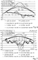
- the course of the transformer current i HF through the transformer coil 15 together with its first derivative after the time is shown in the mains voltage maximum.
- the transformer current i HF itself is shown in solid lines and the first derivative is shown in broken lines.
- the slight increase in the first derivative at around 6 ⁇ s is a sign that the ferrites are saturated and the transformer current i HF is increasing again.
- One possibility of the saturation control could therefore be to detect the course of the transmitter current i HF and to form the first derivative thereof. If this increases briefly in the range between one tenth of the period of the transmitter current, ie 4 ⁇ s, and one quarter of the period, i.e. 10 ⁇ s, in an actually decreasing range, then this is an indication of the beginning of saturation in the ferrites 16.
- This increase should last at least 1 ⁇ s and / or at least 5% or even at least 10% of the signal level at this point in time. If these conditions exist or are fulfilled, an onset of saturation in the ferrites 16 can be recognized and the transmitter current i HF can be reduced, for example by 10% or 20%. Then this brief increase in the first derivative of the transmitter current i HF should no longer occur, otherwise the transmitter current i HF would have to be reduced further.
- the enveloping curve of the peak values of the transmitter current i HF is shown with the thin solid line. There is no saturation, a thick dotted line as an indicator of saturation is constantly zero.
- the first derivative of the enveloping curve, which is not itself shown here, is shown here in two variants. According to the aforementioned first possibility, this signal of the first derivative is smoothed by two low-pass filters with clearly different time constants.
- the curve of the first derivative after smoothing by the first low pass is shown in thin dash-dotted lines.
- the curve of the first derivative after smoothing by the second low pass is shown in solid lines.
- the thin dash-dotted curve after the first low-pass filter with a relatively small time constant advantageously twice the period of the RF oscillation of the transmitter current itself, has not changed much per se compared to the first derivative.
- the solid curve after the second low-pass filter with a significantly larger time constant advantageously ten times the period of the HF oscillation, possibly up to twenty times, is, so to speak, significantly slower or smoothed.
- An indicator of the saturation is shown in dotted lines.
- Fig. 4 shows an onset of saturation in the ferrites 16, as the thinly dashed signal after the second low pass in the time window between 3 ms and 5 ms after the zero crossing of the envelope curve of the transformer current, which is particularly observed here, no longer drops properly.
- the signal even rises slightly here, and the thinly dash-dotted curve of the first derivative with the first, fast low pass easily breaks through the thinly dashed curve of the slower, second low pass.
- the thick solid curve of the second derivative coming from below penetrates the x-axis in this time window, which in the Fig. 3 wasn't the case either. For this reason too, the dotted curve of the saturation indicator shows an increase. Up to this operating point, inductive energy transmission by means of the device 11 can still be advantageously operated, the saturation of the ferrites 16 is still relatively low, and the losses resulting from this are also still relatively low.
- the thin dash-dotted curve after the first low pass pierces the thin dashed curve after the second low pass at approximately 3.5 ms upwards, i.e. in the stated time window, and runs slightly larger than it for 1 ms , This can also be recognized as an indicator of this strong saturation, as previously explained.
- this curve rises again significantly after the second low-pass filter, namely from about 6 A / ms to 8 A / ms, i.e. significantly more than the 7% or 10% mentioned at the beginning.
- the duration of this increase is just over 0.5 ms.
- this time window is between 3.5 ms and 4.1 ms.
- the first derivative of the enveloping curves which is shown in each case, is also formed here.
- the first derivative for the peak current of 38 A is shown with a solid line
- the first derivative for the peak current of 42 A is shown with a solid line
- the first derivative for the peak current of 50 A is shown with thin lines
- the first derivative for the peak current of 64 A is shown in thick lines. From the Fig. 6 it can be seen that in the aforementioned time window between 3 ms and 5 ms after the zero crossing of the enveloping curve, the first derivative of the peak current of 50 A remains approximately the same with small fluctuations. With a peak current of 64 A and a strong saturation, the corresponding thick dashed curve increases significantly, while it continues to decrease with the two smaller peak currents.
- the respective second derivative is then shown, in the same way for the courses with different peak currents as for the first derivative in Fig. 6 , It can be seen here that in the time window shown between 3 ms and 5 ms after the zero crossing of the enveloping curve, the thinly dashed curve of the second derivative at a peak current of 50 A slightly exceeds the indicated limit value of 1.0 A / ms 2 , and twice. This also enables the onset of saturation and thus a good control point to be recognized. Furthermore, here in the Fig. 7 can still be seen that the second derivative for the next smaller peak current of 42 A remains significantly below this limit in this time window. The thick dashed second derivative of the curve at a peak current of 64 A is many times higher. In this way, the additional condition can also be defined in a very general way that the transformer current is regulated in such a way that the second derivative in this time window should be between 1.0 and 1.5 or between 1.0 and 2 A / ms 2 .
Landscapes
- Engineering & Computer Science (AREA)
- Power Engineering (AREA)
- Computer Networks & Wireless Communication (AREA)
- Physics & Mathematics (AREA)
- Electromagnetism (AREA)
- Signal Processing (AREA)
- General Induction Heating (AREA)
- Near-Field Transmission Systems (AREA)
Priority Applications (1)
| Application Number | Priority Date | Filing Date | Title |
|---|---|---|---|
| PL19186440T PL3606284T3 (pl) | 2018-07-30 | 2019-07-16 | Sposób i urządzenie do indukcyjnego przesyłania energii |
Applications Claiming Priority (1)
| Application Number | Priority Date | Filing Date | Title |
|---|---|---|---|
| DE102018212680.1A DE102018212680A1 (de) | 2018-07-30 | 2018-07-30 | Verfahren und Vorrichtung zur induktiven Energieübertragung |
Publications (2)
| Publication Number | Publication Date |
|---|---|
| EP3606284A1 true EP3606284A1 (fr) | 2020-02-05 |
| EP3606284B1 EP3606284B1 (fr) | 2022-01-05 |
Family
ID=67314612
Family Applications (1)
| Application Number | Title | Priority Date | Filing Date |
|---|---|---|---|
| EP19186440.4A Active EP3606284B1 (fr) | 2018-07-30 | 2019-07-16 | Procédé et dispositif de transmission inductive d'énergie |
Country Status (6)
| Country | Link |
|---|---|
| EP (1) | EP3606284B1 (fr) |
| KR (1) | KR102716542B1 (fr) |
| CN (1) | CN110784024B (fr) |
| DE (1) | DE102018212680A1 (fr) |
| ES (1) | ES2910155T3 (fr) |
| PL (1) | PL3606284T3 (fr) |
Cited By (1)
| Publication number | Priority date | Publication date | Assignee | Title |
|---|---|---|---|---|
| CN117439283A (zh) * | 2021-01-29 | 2024-01-23 | 苹果公司 | 用于减轻无线功率系统中的饱和的方法和电路 |
Citations (5)
| Publication number | Priority date | Publication date | Assignee | Title |
|---|---|---|---|---|
| DE102012219040A1 (de) | 2012-10-18 | 2013-11-28 | E.G.O. Elektro-Gerätebau GmbH | Anzeigevorrichtung für ein Kochgerät und Kochgerät |
| EP2798911A1 (fr) | 2011-12-30 | 2014-11-05 | Arçelik Anonim Sirketi | Système de communication de table de cuisson chauffant par induction |
| EP2916432A1 (fr) * | 2014-03-06 | 2015-09-09 | Electrolux Appliances Aktiebolag | Dispositif électrique |
| WO2018070003A1 (fr) * | 2016-10-13 | 2018-04-19 | 三菱電機株式会社 | Dispositif de transmission d'énergie sans contact et système de transmission d'énergie sans contact |
| KR20180085319A (ko) * | 2017-01-18 | 2018-07-26 | 엘지전자 주식회사 | 유도 가열 및 무선 전력 전송 장치 |
Family Cites Families (5)
| Publication number | Priority date | Publication date | Assignee | Title |
|---|---|---|---|---|
| NZ329195A (en) * | 1997-11-17 | 2000-07-28 | Auckland Uniservices Ltd | Loosely coupled inductive power transfer using resonant pickup circuit, inductor core chosen to saturate under overload conditions |
| US10141770B2 (en) * | 2011-01-18 | 2018-11-27 | Mojo Mobility, Inc. | Powering and/or charging with a plurality of protocols |
| CN102832721B (zh) * | 2012-08-23 | 2015-03-18 | 广东电网公司佛山供电局 | 一种取能电源线圈气隙的调整方法 |
| KR20140130837A (ko) | 2013-05-02 | 2014-11-12 | 엘지이노텍 주식회사 | 무선전력 수신장치 |
| US9391470B2 (en) * | 2013-11-06 | 2016-07-12 | Blackberry Limited | Energy transfer optimization by detecting and mitigating magnetic saturation in wireless charging with foreign object detection |
-
2018
- 2018-07-30 DE DE102018212680.1A patent/DE102018212680A1/de not_active Withdrawn
-
2019
- 2019-07-16 ES ES19186440T patent/ES2910155T3/es active Active
- 2019-07-16 PL PL19186440T patent/PL3606284T3/pl unknown
- 2019-07-16 EP EP19186440.4A patent/EP3606284B1/fr active Active
- 2019-07-22 KR KR1020190088599A patent/KR102716542B1/ko active Active
- 2019-07-30 CN CN201910696080.1A patent/CN110784024B/zh active Active
Patent Citations (6)
| Publication number | Priority date | Publication date | Assignee | Title |
|---|---|---|---|---|
| EP2798911A1 (fr) | 2011-12-30 | 2014-11-05 | Arçelik Anonim Sirketi | Système de communication de table de cuisson chauffant par induction |
| DE102012219040A1 (de) | 2012-10-18 | 2013-11-28 | E.G.O. Elektro-Gerätebau GmbH | Anzeigevorrichtung für ein Kochgerät und Kochgerät |
| EP2916432A1 (fr) * | 2014-03-06 | 2015-09-09 | Electrolux Appliances Aktiebolag | Dispositif électrique |
| WO2018070003A1 (fr) * | 2016-10-13 | 2018-04-19 | 三菱電機株式会社 | Dispositif de transmission d'énergie sans contact et système de transmission d'énergie sans contact |
| EP3528363A1 (fr) * | 2016-10-13 | 2019-08-21 | Mitsubishi Electric Corporation | Dispositif de transmission d'énergie sans contact et système de transmission d'énergie sans contact |
| KR20180085319A (ko) * | 2017-01-18 | 2018-07-26 | 엘지전자 주식회사 | 유도 가열 및 무선 전력 전송 장치 |
Cited By (4)
| Publication number | Priority date | Publication date | Assignee | Title |
|---|---|---|---|---|
| CN117439283A (zh) * | 2021-01-29 | 2024-01-23 | 苹果公司 | 用于减轻无线功率系统中的饱和的方法和电路 |
| CN117439283B (zh) * | 2021-01-29 | 2025-02-25 | 苹果公司 | 用于减轻无线功率系统中的饱和的方法和电路 |
| US12374935B2 (en) | 2021-01-29 | 2025-07-29 | Apple Inc. | Methods and circuitry for mitigating saturation in wireless power systems |
| US12456886B2 (en) | 2021-01-29 | 2025-10-28 | Apple Inc. | Methods and circuitry for mitigating saturation in wireless power systems |
Also Published As
| Publication number | Publication date |
|---|---|
| KR20200013597A (ko) | 2020-02-07 |
| EP3606284B1 (fr) | 2022-01-05 |
| CN110784024A (zh) | 2020-02-11 |
| CN110784024B (zh) | 2024-07-05 |
| KR102716542B1 (ko) | 2024-10-11 |
| PL3606284T3 (pl) | 2022-05-09 |
| DE102018212680A1 (de) | 2020-01-30 |
| ES2910155T3 (es) | 2022-05-11 |
Similar Documents
| Publication | Publication Date | Title |
|---|---|---|
| DE69516979T2 (de) | Induktionskochstelle mit temperaturgeschütztem Induktor | |
| EP2087770B1 (fr) | Procédé de commande d'un appareil de cuisson par induction, et appareil de cuisson par induction | |
| DE3612707C2 (fr) | ||
| EP1625774B2 (fr) | Regulation de temperature destinee a un element de chauffage chauffe par induction | |
| EP2483999B1 (fr) | Procédé et circuit de un-pin correction du facteur de puissance | |
| EP3500421B1 (fr) | Procédé de réparation d'une pièce en matière plastique, dispositif de réparation | |
| DE2317565A1 (de) | Anordnung zur erhitzung eines elektrisch leitenden kochgeraets durch magnetische induktion | |
| EP0561219A1 (fr) | Places de cuisson à chauffage inductif | |
| DE102019202991A1 (de) | Verfahren zur Ansteuerung einer Induktionsspule und Induktionsspulenvorrichtung | |
| DE2329743A1 (de) | Induktionsheizeinrichtung, insbesondere als haushaltsherd | |
| DE602005003310T2 (de) | Umrichterschaltung für Induktionsheizvorrichtung, Kochgerät mit einer solchen Schaltung und Betriebsverfahren | |
| WO2015197697A1 (fr) | Alimentation à découpage | |
| EP2384083A1 (fr) | Agencement de commutation pour un appareil de cuisson à induction, procédé de fonctionnement d'un agencement de commutation et appareil de cuisson à induction | |
| EP3066888B2 (fr) | Dispositif table de cuisson à induction | |
| EP1734789B1 (fr) | Procédé et dispositif d'alimentation pour un appareil de chauffage à induction | |
| EP0561207A2 (fr) | Commande d'une plaque de cuisson à induction | |
| EP2506673B1 (fr) | Plaque de cuisson a induction | |
| EP3606284B1 (fr) | Procédé et dispositif de transmission inductive d'énergie | |
| WO1993013634A1 (fr) | Procede et dispositif pour le chauffage par induction de recipients de differentes dimensions | |
| EP3740033B1 (fr) | Module de bobine d'induction et procédé de commande d'un processus de chauffage par induction pour module de bobine d'induction | |
| EP3136822B1 (fr) | Procede de determination de temperature | |
| DE2559519C3 (de) | Vorrichtung zur Überwachung der Belastung eines Induktionskochgerates | |
| DE102017114951A1 (de) | Verfahren zum Betrieb einer Kochstelle eines Induktionskochfelds mit einem Kochgeschirr | |
| DE102004033115A1 (de) | Verfahren und Vorrichtung zur thermostatischen Kochgeschirrregelung | |
| EP2663159B1 (fr) | Dispositif d'appareil de cuisson |
Legal Events
| Date | Code | Title | Description |
|---|---|---|---|
| PUAI | Public reference made under article 153(3) epc to a published international application that has entered the european phase |
Free format text: ORIGINAL CODE: 0009012 |
|
| STAA | Information on the status of an ep patent application or granted ep patent |
Free format text: STATUS: THE APPLICATION HAS BEEN PUBLISHED |
|
| AK | Designated contracting states |
Kind code of ref document: A1 Designated state(s): AL AT BE BG CH CY CZ DE DK EE ES FI FR GB GR HR HU IE IS IT LI LT LU LV MC MK MT NL NO PL PT RO RS SE SI SK SM TR |
|
| AX | Request for extension of the european patent |
Extension state: BA ME |
|
| STAA | Information on the status of an ep patent application or granted ep patent |
Free format text: STATUS: REQUEST FOR EXAMINATION WAS MADE |
|
| 17P | Request for examination filed |
Effective date: 20200708 |
|
| RBV | Designated contracting states (corrected) |
Designated state(s): AL AT BE BG CH CY CZ DE DK EE ES FI FR GB GR HR HU IE IS IT LI LT LU LV MC MK MT NL NO PL PT RO RS SE SI SK SM TR |
|
| GRAP | Despatch of communication of intention to grant a patent |
Free format text: ORIGINAL CODE: EPIDOSNIGR1 |
|
| STAA | Information on the status of an ep patent application or granted ep patent |
Free format text: STATUS: GRANT OF PATENT IS INTENDED |
|
| INTG | Intention to grant announced |
Effective date: 20210803 |
|
| GRAS | Grant fee paid |
Free format text: ORIGINAL CODE: EPIDOSNIGR3 |
|
| GRAA | (expected) grant |
Free format text: ORIGINAL CODE: 0009210 |
|
| STAA | Information on the status of an ep patent application or granted ep patent |
Free format text: STATUS: THE PATENT HAS BEEN GRANTED |
|
| AK | Designated contracting states |
Kind code of ref document: B1 Designated state(s): AL AT BE BG CH CY CZ DE DK EE ES FI FR GB GR HR HU IE IS IT LI LT LU LV MC MK MT NL NO PL PT RO RS SE SI SK SM TR |
|
| REG | Reference to a national code |
Ref country code: GB Ref legal event code: FG4D Free format text: NOT ENGLISH |
|
| REG | Reference to a national code |
Ref country code: CH Ref legal event code: EP |
|
| REG | Reference to a national code |
Ref country code: AT Ref legal event code: REF Ref document number: 1461748 Country of ref document: AT Kind code of ref document: T Effective date: 20220115 |
|
| REG | Reference to a national code |
Ref country code: DE Ref legal event code: R096 Ref document number: 502019003145 Country of ref document: DE |
|
| REG | Reference to a national code |
Ref country code: IE Ref legal event code: FG4D Free format text: LANGUAGE OF EP DOCUMENT: GERMAN |
|
| REG | Reference to a national code |
Ref country code: LT Ref legal event code: MG9D |
|
| REG | Reference to a national code |
Ref country code: NL Ref legal event code: MP Effective date: 20220105 Ref country code: ES Ref legal event code: FG2A Ref document number: 2910155 Country of ref document: ES Kind code of ref document: T3 Effective date: 20220511 |
|
| PG25 | Lapsed in a contracting state [announced via postgrant information from national office to epo] |
Ref country code: NL Free format text: LAPSE BECAUSE OF FAILURE TO SUBMIT A TRANSLATION OF THE DESCRIPTION OR TO PAY THE FEE WITHIN THE PRESCRIBED TIME-LIMIT Effective date: 20220105 |
|
| PG25 | Lapsed in a contracting state [announced via postgrant information from national office to epo] |
Ref country code: SE Free format text: LAPSE BECAUSE OF FAILURE TO SUBMIT A TRANSLATION OF THE DESCRIPTION OR TO PAY THE FEE WITHIN THE PRESCRIBED TIME-LIMIT Effective date: 20220105 Ref country code: RS Free format text: LAPSE BECAUSE OF FAILURE TO SUBMIT A TRANSLATION OF THE DESCRIPTION OR TO PAY THE FEE WITHIN THE PRESCRIBED TIME-LIMIT Effective date: 20220105 Ref country code: PT Free format text: LAPSE BECAUSE OF FAILURE TO SUBMIT A TRANSLATION OF THE DESCRIPTION OR TO PAY THE FEE WITHIN THE PRESCRIBED TIME-LIMIT Effective date: 20220505 Ref country code: NO Free format text: LAPSE BECAUSE OF FAILURE TO SUBMIT A TRANSLATION OF THE DESCRIPTION OR TO PAY THE FEE WITHIN THE PRESCRIBED TIME-LIMIT Effective date: 20220405 Ref country code: LT Free format text: LAPSE BECAUSE OF FAILURE TO SUBMIT A TRANSLATION OF THE DESCRIPTION OR TO PAY THE FEE WITHIN THE PRESCRIBED TIME-LIMIT Effective date: 20220105 Ref country code: HR Free format text: LAPSE BECAUSE OF FAILURE TO SUBMIT A TRANSLATION OF THE DESCRIPTION OR TO PAY THE FEE WITHIN THE PRESCRIBED TIME-LIMIT Effective date: 20220105 Ref country code: BG Free format text: LAPSE BECAUSE OF FAILURE TO SUBMIT A TRANSLATION OF THE DESCRIPTION OR TO PAY THE FEE WITHIN THE PRESCRIBED TIME-LIMIT Effective date: 20220405 |
|
| PG25 | Lapsed in a contracting state [announced via postgrant information from national office to epo] |
Ref country code: LV Free format text: LAPSE BECAUSE OF FAILURE TO SUBMIT A TRANSLATION OF THE DESCRIPTION OR TO PAY THE FEE WITHIN THE PRESCRIBED TIME-LIMIT Effective date: 20220105 Ref country code: GR Free format text: LAPSE BECAUSE OF FAILURE TO SUBMIT A TRANSLATION OF THE DESCRIPTION OR TO PAY THE FEE WITHIN THE PRESCRIBED TIME-LIMIT Effective date: 20220406 Ref country code: FI Free format text: LAPSE BECAUSE OF FAILURE TO SUBMIT A TRANSLATION OF THE DESCRIPTION OR TO PAY THE FEE WITHIN THE PRESCRIBED TIME-LIMIT Effective date: 20220105 |
|
| PG25 | Lapsed in a contracting state [announced via postgrant information from national office to epo] |
Ref country code: IS Free format text: LAPSE BECAUSE OF FAILURE TO SUBMIT A TRANSLATION OF THE DESCRIPTION OR TO PAY THE FEE WITHIN THE PRESCRIBED TIME-LIMIT Effective date: 20220505 |
|
| REG | Reference to a national code |
Ref country code: DE Ref legal event code: R097 Ref document number: 502019003145 Country of ref document: DE |
|
| PG25 | Lapsed in a contracting state [announced via postgrant information from national office to epo] |
Ref country code: SM Free format text: LAPSE BECAUSE OF FAILURE TO SUBMIT A TRANSLATION OF THE DESCRIPTION OR TO PAY THE FEE WITHIN THE PRESCRIBED TIME-LIMIT Effective date: 20220105 Ref country code: SK Free format text: LAPSE BECAUSE OF FAILURE TO SUBMIT A TRANSLATION OF THE DESCRIPTION OR TO PAY THE FEE WITHIN THE PRESCRIBED TIME-LIMIT Effective date: 20220105 Ref country code: RO Free format text: LAPSE BECAUSE OF FAILURE TO SUBMIT A TRANSLATION OF THE DESCRIPTION OR TO PAY THE FEE WITHIN THE PRESCRIBED TIME-LIMIT Effective date: 20220105 Ref country code: EE Free format text: LAPSE BECAUSE OF FAILURE TO SUBMIT A TRANSLATION OF THE DESCRIPTION OR TO PAY THE FEE WITHIN THE PRESCRIBED TIME-LIMIT Effective date: 20220105 Ref country code: DK Free format text: LAPSE BECAUSE OF FAILURE TO SUBMIT A TRANSLATION OF THE DESCRIPTION OR TO PAY THE FEE WITHIN THE PRESCRIBED TIME-LIMIT Effective date: 20220105 Ref country code: CZ Free format text: LAPSE BECAUSE OF FAILURE TO SUBMIT A TRANSLATION OF THE DESCRIPTION OR TO PAY THE FEE WITHIN THE PRESCRIBED TIME-LIMIT Effective date: 20220105 |
|
| PLBE | No opposition filed within time limit |
Free format text: ORIGINAL CODE: 0009261 |
|
| STAA | Information on the status of an ep patent application or granted ep patent |
Free format text: STATUS: NO OPPOSITION FILED WITHIN TIME LIMIT |
|
| PG25 | Lapsed in a contracting state [announced via postgrant information from national office to epo] |
Ref country code: AL Free format text: LAPSE BECAUSE OF FAILURE TO SUBMIT A TRANSLATION OF THE DESCRIPTION OR TO PAY THE FEE WITHIN THE PRESCRIBED TIME-LIMIT Effective date: 20220105 |
|
| 26N | No opposition filed |
Effective date: 20221006 |
|
| PG25 | Lapsed in a contracting state [announced via postgrant information from national office to epo] |
Ref country code: SI Free format text: LAPSE BECAUSE OF FAILURE TO SUBMIT A TRANSLATION OF THE DESCRIPTION OR TO PAY THE FEE WITHIN THE PRESCRIBED TIME-LIMIT Effective date: 20220105 Ref country code: MC Free format text: LAPSE BECAUSE OF FAILURE TO SUBMIT A TRANSLATION OF THE DESCRIPTION OR TO PAY THE FEE WITHIN THE PRESCRIBED TIME-LIMIT Effective date: 20220105 |
|
| REG | Reference to a national code |
Ref country code: CH Ref legal event code: PL |
|
| REG | Reference to a national code |
Ref country code: BE Ref legal event code: MM Effective date: 20220731 |
|
| PG25 | Lapsed in a contracting state [announced via postgrant information from national office to epo] |
Ref country code: LU Free format text: LAPSE BECAUSE OF NON-PAYMENT OF DUE FEES Effective date: 20220716 Ref country code: LI Free format text: LAPSE BECAUSE OF NON-PAYMENT OF DUE FEES Effective date: 20220731 Ref country code: CH Free format text: LAPSE BECAUSE OF NON-PAYMENT OF DUE FEES Effective date: 20220731 |
|
| PG25 | Lapsed in a contracting state [announced via postgrant information from national office to epo] |
Ref country code: BE Free format text: LAPSE BECAUSE OF NON-PAYMENT OF DUE FEES Effective date: 20220731 |
|
| PG25 | Lapsed in a contracting state [announced via postgrant information from national office to epo] |
Ref country code: IE Free format text: LAPSE BECAUSE OF NON-PAYMENT OF DUE FEES Effective date: 20220716 |
|
| PGFP | Annual fee paid to national office [announced via postgrant information from national office to epo] |
Ref country code: PL Payment date: 20230612 Year of fee payment: 5 |
|
| PGFP | Annual fee paid to national office [announced via postgrant information from national office to epo] |
Ref country code: IT Payment date: 20230731 Year of fee payment: 5 Ref country code: GB Payment date: 20230724 Year of fee payment: 5 Ref country code: ES Payment date: 20230821 Year of fee payment: 5 |
|
| PGFP | Annual fee paid to national office [announced via postgrant information from national office to epo] |
Ref country code: FR Payment date: 20230724 Year of fee payment: 5 |
|
| PG25 | Lapsed in a contracting state [announced via postgrant information from national office to epo] |
Ref country code: HU Free format text: LAPSE BECAUSE OF FAILURE TO SUBMIT A TRANSLATION OF THE DESCRIPTION OR TO PAY THE FEE WITHIN THE PRESCRIBED TIME-LIMIT; INVALID AB INITIO Effective date: 20190716 |
|
| PG25 | Lapsed in a contracting state [announced via postgrant information from national office to epo] |
Ref country code: MK Free format text: LAPSE BECAUSE OF FAILURE TO SUBMIT A TRANSLATION OF THE DESCRIPTION OR TO PAY THE FEE WITHIN THE PRESCRIBED TIME-LIMIT Effective date: 20220105 Ref country code: CY Free format text: LAPSE BECAUSE OF FAILURE TO SUBMIT A TRANSLATION OF THE DESCRIPTION OR TO PAY THE FEE WITHIN THE PRESCRIBED TIME-LIMIT Effective date: 20220105 |
|
| PG25 | Lapsed in a contracting state [announced via postgrant information from national office to epo] |
Ref country code: TR Free format text: LAPSE BECAUSE OF FAILURE TO SUBMIT A TRANSLATION OF THE DESCRIPTION OR TO PAY THE FEE WITHIN THE PRESCRIBED TIME-LIMIT Effective date: 20220105 |
|
| PG25 | Lapsed in a contracting state [announced via postgrant information from national office to epo] |
Ref country code: MT Free format text: LAPSE BECAUSE OF FAILURE TO SUBMIT A TRANSLATION OF THE DESCRIPTION OR TO PAY THE FEE WITHIN THE PRESCRIBED TIME-LIMIT Effective date: 20220105 |
|
| GBPC | Gb: european patent ceased through non-payment of renewal fee |
Effective date: 20240716 |
|
| PG25 | Lapsed in a contracting state [announced via postgrant information from national office to epo] |
Ref country code: FR Free format text: LAPSE BECAUSE OF NON-PAYMENT OF DUE FEES Effective date: 20240731 |
|
| PG25 | Lapsed in a contracting state [announced via postgrant information from national office to epo] |
Ref country code: GB Free format text: LAPSE BECAUSE OF NON-PAYMENT OF DUE FEES Effective date: 20240716 |
|
| PG25 | Lapsed in a contracting state [announced via postgrant information from national office to epo] |
Ref country code: IT Free format text: LAPSE BECAUSE OF NON-PAYMENT OF DUE FEES Effective date: 20240716 |
|
| REG | Reference to a national code |
Ref country code: ES Ref legal event code: FD2A Effective date: 20250828 |
|
| REG | Reference to a national code |
Ref country code: AT Ref legal event code: MM01 Ref document number: 1461748 Country of ref document: AT Kind code of ref document: T Effective date: 20240716 |
|
| PG25 | Lapsed in a contracting state [announced via postgrant information from national office to epo] |
Ref country code: ES Free format text: LAPSE BECAUSE OF NON-PAYMENT OF DUE FEES Effective date: 20240717 |
|
| PGFP | Annual fee paid to national office [announced via postgrant information from national office to epo] |
Ref country code: DE Payment date: 20250723 Year of fee payment: 7 |
|
| PG25 | Lapsed in a contracting state [announced via postgrant information from national office to epo] |
Ref country code: AT Free format text: LAPSE BECAUSE OF NON-PAYMENT OF DUE FEES Effective date: 20240716 |
|
| PG25 | Lapsed in a contracting state [announced via postgrant information from national office to epo] |
Ref country code: PL Free format text: LAPSE BECAUSE OF NON-PAYMENT OF DUE FEES Effective date: 20240716 |
|
| PGFP | Annual fee paid to national office [announced via postgrant information from national office to epo] |
Ref country code: AT Payment date: 20260410 Year of fee payment: 5 |