EP3606568B1 - Implant à changement de propriété - Google Patents
Implant à changement de propriété Download PDFInfo
- Publication number
- EP3606568B1 EP3606568B1 EP18722740.0A EP18722740A EP3606568B1 EP 3606568 B1 EP3606568 B1 EP 3606568B1 EP 18722740 A EP18722740 A EP 18722740A EP 3606568 B1 EP3606568 B1 EP 3606568B1
- Authority
- EP
- European Patent Office
- Prior art keywords
- cross
- implant
- polymer
- group
- linking
- Prior art date
- Legal status (The legal status is an assumption and is not a legal conclusion. Google has not performed a legal analysis and makes no representation as to the accuracy of the status listed.)
- Active
Links
Images





Classifications
-
- A—HUMAN NECESSITIES
- A61—MEDICAL OR VETERINARY SCIENCE; HYGIENE
- A61L—METHODS OR APPARATUS FOR STERILISING MATERIALS OR OBJECTS IN GENERAL; DISINFECTION, STERILISATION OR DEODORISATION OF AIR; CHEMICAL ASPECTS OF BANDAGES, DRESSINGS, ABSORBENT PADS OR SURGICAL ARTICLES; MATERIALS FOR BANDAGES, DRESSINGS, ABSORBENT PADS OR SURGICAL ARTICLES
- A61L27/00—Materials for grafts or prostheses or for coating grafts or prostheses
- A61L27/14—Macromolecular materials
- A61L27/16—Macromolecular materials obtained by reactions only involving carbon-to-carbon unsaturated bonds
-
- A—HUMAN NECESSITIES
- A61—MEDICAL OR VETERINARY SCIENCE; HYGIENE
- A61L—METHODS OR APPARATUS FOR STERILISING MATERIALS OR OBJECTS IN GENERAL; DISINFECTION, STERILISATION OR DEODORISATION OF AIR; CHEMICAL ASPECTS OF BANDAGES, DRESSINGS, ABSORBENT PADS OR SURGICAL ARTICLES; MATERIALS FOR BANDAGES, DRESSINGS, ABSORBENT PADS OR SURGICAL ARTICLES
- A61L27/00—Materials for grafts or prostheses or for coating grafts or prostheses
- A61L27/14—Macromolecular materials
- A61L27/18—Macromolecular materials obtained otherwise than by reactions only involving carbon-to-carbon unsaturated bonds
-
- A—HUMAN NECESSITIES
- A61—MEDICAL OR VETERINARY SCIENCE; HYGIENE
- A61L—METHODS OR APPARATUS FOR STERILISING MATERIALS OR OBJECTS IN GENERAL; DISINFECTION, STERILISATION OR DEODORISATION OF AIR; CHEMICAL ASPECTS OF BANDAGES, DRESSINGS, ABSORBENT PADS OR SURGICAL ARTICLES; MATERIALS FOR BANDAGES, DRESSINGS, ABSORBENT PADS OR SURGICAL ARTICLES
- A61L27/00—Materials for grafts or prostheses or for coating grafts or prostheses
- A61L27/50—Materials characterised by their function or physical properties, e.g. injectable or lubricating compositions, shape-memory materials, surface modified materials
-
- A—HUMAN NECESSITIES
- A61—MEDICAL OR VETERINARY SCIENCE; HYGIENE
- A61L—METHODS OR APPARATUS FOR STERILISING MATERIALS OR OBJECTS IN GENERAL; DISINFECTION, STERILISATION OR DEODORISATION OF AIR; CHEMICAL ASPECTS OF BANDAGES, DRESSINGS, ABSORBENT PADS OR SURGICAL ARTICLES; MATERIALS FOR BANDAGES, DRESSINGS, ABSORBENT PADS OR SURGICAL ARTICLES
- A61L27/00—Materials for grafts or prostheses or for coating grafts or prostheses
- A61L27/50—Materials characterised by their function or physical properties, e.g. injectable or lubricating compositions, shape-memory materials, surface modified materials
- A61L27/56—Porous materials, e.g. foams or sponges
-
- A—HUMAN NECESSITIES
- A61—MEDICAL OR VETERINARY SCIENCE; HYGIENE
- A61L—METHODS OR APPARATUS FOR STERILISING MATERIALS OR OBJECTS IN GENERAL; DISINFECTION, STERILISATION OR DEODORISATION OF AIR; CHEMICAL ASPECTS OF BANDAGES, DRESSINGS, ABSORBENT PADS OR SURGICAL ARTICLES; MATERIALS FOR BANDAGES, DRESSINGS, ABSORBENT PADS OR SURGICAL ARTICLES
- A61L2430/00—Materials or treatment for tissue regeneration
- A61L2430/02—Materials or treatment for tissue regeneration for reconstruction of bones; weight-bearing implants
-
- A—HUMAN NECESSITIES
- A61—MEDICAL OR VETERINARY SCIENCE; HYGIENE
- A61L—METHODS OR APPARATUS FOR STERILISING MATERIALS OR OBJECTS IN GENERAL; DISINFECTION, STERILISATION OR DEODORISATION OF AIR; CHEMICAL ASPECTS OF BANDAGES, DRESSINGS, ABSORBENT PADS OR SURGICAL ARTICLES; MATERIALS FOR BANDAGES, DRESSINGS, ABSORBENT PADS OR SURGICAL ARTICLES
- A61L2430/00—Materials or treatment for tissue regeneration
- A61L2430/24—Materials or treatment for tissue regeneration for joint reconstruction
Definitions
- the present invention in some embodiments thereof, relates to medical grade materials which are configured to change their property following stimulation.
- Bone fractures are caused by high force impact or stress, where the fracture is then properly termed a traumatic fracture, or as by certain medical conditions that weaken the bones, such as osteoporosis, metastatic bone disease, or osteogenesis imperfecta, where the fracture is then properly termed a pathologic fracture.
- a common surgery procedure to treat bone fractions comprises in the use of orthopedic implants for replacing or supplementing or augmentation of the fractured or degenerated bone.
- orthopedic implants for replacing or supplementing or augmentation of the fractured or degenerated bone.
- Numerous types of biocompatible orthopedic implants are available. Some are made of solid metals, such as stainless steel, cobalt-chromium-molybdenum alloy, tungsten, titanium, cobalt-chromium-tungsten-nickel, and similar alloys. Others are made of solid polymers compounds such as polyetheretherketone (PEEK). Some orthopedic implants are also made of ceramics or composite materials.
- Orthopedic implants are available either pre-shaped to their final structure after implant, or expandable implants that enable minimally invasive insertion and then deploy to final form.
- Implants that are pre-shaped to their final structure such as nail implants, stem implants and plate implants are in most cases stronger and can be implemented in almost any required shape or size.
- the main disadvantage of the pre-shaped implants is that in many cases an open surgery is needed in order to position and secure the implant. Open surgery involves large incisions and longer recovery time.
- Expandable implants such as lumbar expandable cage or stents can be implanted in a minimally invasive procedure that result in less scars and faster recovery time, but the design of the implant is more complicated and the implant structure is limited in shape and size.
- Both pre-shaped implants and expandable implants that are made from solid, non-elastic parts share one major disadvantage; implants are made in different shapes and sizes, but they have very limited possibility to perfectly adjust to the optimal configuration of each patient anatomy.
- One way to apply an implant that will perfectly match the required anatomy and can be implanted via a minimally invasive procedure is by injecting adhesives or cement such as Poly Methyl Methacrylate (PMMA).
- PMMA Poly Methyl Methacrylate
- the PMMA is injected while in a liquid state.
- the PMMA cement is then cured at the target site resolved in a solid matter that perfectly matches the desired anatomy.
- This method is widely used in procedures like Vertebroplasty or Kyphoplasty.
- cement injection has many advantages like pain relief and can be done via a minimally invasive procedure, the use of this technique involves a high risk of cement leakage. Extrusion of the injected cement into the vertebral canal may lead to spinal cord or nerve root compression and paralysis.
- US patent application US2016287516A discloses "an improved polymer delivery system which provides polymeric microparticle compositions and porous microparticles formed therefrom. Pore size, pore architecture as well as particle size are also controllable.
- both the polymeric microparticle compositions and porous microparticles formed therefrom encapsulate at least one substance, such as a biologic substance (one having biologic activity and/or compatible with a biologic system). The encapsulation occurs prior to polymerization. The amount of substance that is encapsulated may be controlled by the described methods. Said methods do not imply organic solvents. As such, the fabrication occurs in a solvent-free system".
- US patent US6340648B discloses "a calcium phosphate porous sintered body which comprises spherical pores communicating with one another substantially throughout the body with a porosity of 55% or more and 90% or less, and has an average diameter of the inter-pore communicating parts of 50 ⁇ m or more, a pore diameter of 150 ⁇ m or more, and a three-point bending strength of 5 MPa or more, and a method for producing the same".
- US patent US6476087B discloses "a method of manufacturing syntactic foam which includes the steps of combining a polymer, microspheres and a solvent to form a slurry. At least a portion of the solvent is removed through a porous wick, and conditions are applied which substantially solidify the polymer".
- US patent application US2011319510A discloses "a silicone rubber sponge-forming emulsion composition is provided that, even when the quantity of reinforcing silica filler is increased, does not exhibit a decline in emulsion stability, avoids defects in cell morphology of the sponge, and avoids a substantial increase in hardness of the sponge. A method of producing a silicone rubber sponge from this composition is also provided.
- the A silicone rubber sponge-forming emulsion composition comprises (A) 100 weight parts of a liquid diorganopolysiloxane that has at least two silicon-bonded alkenyl groups in each molecule, (B) 1 to 50 weight parts of a reinforcing silica filler comprising (b1) a fumed silica and (b2) a precipitated silica in a (b1)/(b2) weight ratio of 0.01/1 to 30/1, (C) 50 to 250 weight parts of water that contains (c) a smectite clay, (D) 0.1 to 7 weight parts of a sorbitan fatty acid ester, (E) 0 to 10 weight parts of an isononanoic acid ester, (F) 0 to 10 weight parts of a Guerbet alcohol, and (G) a curing agent in a quantity sufficient to crosslink and cure component (A)".
- US patent application US2010075056A discloses "a method for fabricating a porous elastomer, the method comprising the steps of: providing a predetermined amount of a liquid elastomer and a predetermined amount of a porogen; mixing the liquid elastomer and the porogen in vacuum until a homogenous emulsion without phase separation is formed; curing the homogenous emulsion until polymerizations of the emulsion is reached, thereby forming a cured emulsion; and removing the porogen from the cured emulsion.
- the method can advantageously be used for forming biocompatible porous elastomers and biocompatible porous membranes".
- thermoplastic resin foam which excels typically in strength, flexibility, cushioning properties, and strain recovery and is especially resistant to cell structure shrinkage caused by the restoring force of resin.
- the thermoplastic resin foam which is obtained by subjecting a thermoplastic resin composition containing a thermoplastic elastomer and an active-energy-ray-curable resin to foam molding to give a foamed structure, and irradiating the foamed structure with an active energy ray to allow the active-energy-ray-curable resin to form a cross-linked structure in the foamed structure.
- thermoplastic resin foam which is obtained by subjecting a thermoplastic resin composition containing a thermoplastic elastomer, an active-energy-ray-curable resin, and a thermal cross-linking agent to foam molding to give a foamed structure, irradiating the foamed structure with an active energy ray to allow the active-energy-ray-curable resin to form a cross-linked structure in the foamed structure, and heating the resulting foamed structure bearing the cross-linked structure to thereby allow the thermal cross-linking agent to form another cross-linked structure in the foamed structure.
- Chinese patent application CN101966409A discloses "a novel macromolecular filter material and a preparation method thereof.
- the method comprises the following steps of: performing cross-linking curing on polyvinyl alcohol linear macromolecular filter material, foaming auxiliary agent, cross linker and catalyst, performing foaming at the early stage or the medium-late stage of the cross-linking curing link to form porous foam, then further performing cross-linking ageing to obtain sponge matrix, cleaning the sponge matrix, and hardening the sponge matrix; and finally, cleaning and shearing the hardened product to obtain the novel macromolecular filter material.
- the method can adjust the density and diameter of foam holes in a large range and can load a filter modified material; and the obtained novel macromolecular composite filter material has the advantages of good hydrophilic or lipophilic property, high filter flow rate, strong chemical weather resistance, good mechanical property, wide variable range of technical parameters, reutilization and natural degradability, and can be widely applied in filter treatment processes of industries of beverage, sugar refining, chemical engineering, industrial oil and the like and in the industries of water treatment, air filter and the like".
- US patent application US2007129456A discloses "heats to melt a urethane prepolymer (A ingredient) including a hydroxyl (-OH) functional group in a liquid state or a semi-solid state at room temperature as itself or temperature at 30° C. to 80° C., an isocyanate compound (B ingredient) for reacting with a hydroxyl functional group of urethane prepolymer, a mixture (C ingredient) of a hardening catalyst by cross-link, a pores formation assistance catalyst, a silicone surfactant, and an additive is added by fixed quantity and agitation at high speed to mix.
- a ingredient including a hydroxyl (-OH) functional group in a liquid state or a semi-solid state at room temperature as itself or temperature at 30° C. to 80° C.
- B ingredient for reacting with a hydroxyl functional group of urethane prepolymer
- C ingredient a hardening catalyst by cross-link
- a pores formation assistance catalyst a silicone surfactant, and
- an artificial marble includes an artificial marble matrix made of a thermosetting resin and metal chips having a cellular structure.
- the metal chips can be evenly dispersed throughout the artificial marble and can form foam or open-cell patterns.
- US patent application US2011275727A discloses "a resin foam which excels in properties such as strength, flexibility, cushioning properties, and strain recovery, particularly has a cell structure resistant to shrinkage caused by the restoring force of the resin, and has a high expansion ratio".
- US patent application US20040220672A1 discloses "an orthopedic implant device that is adapted for providing a support structure in spine treatments and other bone treatments”.
- WO 2011/007352 describes a polymeric medical device in the form of a tubular structure which is implantable in a body vessel and expanded there. The stiffness of the device changes upon stimulation under physiological conditions, such that the expanded tubular structure becomes stiffer and retains the expanded state.
- the polymer can e.g. have functional groups which are capable of crosslinking upon stimulation under physiological conditions.
- An aspect of the present invention relates to a medical grade implant, comprising a porous architecture which allows the passage of liquids and a deformable body formed of a polymer cross-linked by a first cross-link, said polymer comprising functional groups capable of cross-linking to form a second cross-link; said body provided in a first configuration which is cross-linked to a second configuration upon application of a selected stimuli; wherein said selected stimuli causes said cross-linking of said functional groups.
- said stimuli is the initiator of the cross-link between said first configuration to said second configuration.
- said cross-linking of said functional groups is cross-linking with each other.
- said cross-linking of said functional groups is cross-linking with another material.
- said stimuli is a liquid.
- the quantity of said liquid is from about 3% to about 100% of the total implant weight; and wherein the time required for said liquid to finish 80% of the cross-linking is from about 1 minutes to about 30 minutes.
- said stimuli comprises temperature
- said temperature is from about 40 degrees Celsius to about 60 degrees Celsius; and wherein the time required for said stimuli to finish 80% of the cross-linking is from about 5 minutes to about 30 minutes.
- said stimuli comprises ultraviolet (UV) radiation.
- the time required for said UV to finish 80% of the cross-linking is from about 2 seconds to about 5 minutes.
- said stimuli is a monomer.
- said implant in said first configuration said implant has an elastic modulus from about 0.01 to about 1 MPa.
- said device in said second configuration said device has an elastic modulus from about 2 to about 250 MPa.
- said elastic modulus changes from said first configuration to said second configuration by a factor from about 10 to about 1000.
- said body has an open cell structure having a porosity percentage from about 65% to about 85%.
- said open cell structure allows said body to be shrinked by compression.
- said compression is stabilized by dehydratation.
- the stabilized dehydrated body is expandable by hydration.
- the cross-linking from said first configuration to said second configuration comprises a non-uniform cross-linking of said functional groups with each other.
- the cross-linking from said first configuration to said second configuration comprises a non-uniform change of elastic modulus in said implant.
- the cross-linking from said first configuration to said second configuration comprises a non-uniform cross-linking location within said implant.
- the cross-linking from said first configuration to said second configuration comprises a biocompatible cross-linking process.
- said implant comprises at least one pharmacological agent.
- said functional group is comprised by a pendant group attached to said polymer.
- the polymer has formula I: [X]m[X(-L-Y)]n[X-Z-]p Formula I wherein:
- the polymer comprises a plurality of backbone units having formula II: -CR1R2-CR3A- Formula II wherein:
- said polymer is selected from the group consisting of poly(vinyl alcohol) (PVA), polyvinylamine (PVM), poly(vinyl chloride), a fluoropolymer, a polyester, a polyurethane, a polyurea, a silicone, and copolymers thereof.
- said polymer is selected from the group consisting of poly(vinyl alcohol), poly(vinyl alcohol-co-ethylene), poly(vinyl alcohol-co-vinyl acetate), poly(vinyl alcohol-co-methyl methacrylate), poly(vinyl alcohol-co-vinyl butyral), poly(vinyl alcohol-co-vinyl chloride), a block copolymer of poly(vinyl alcohol) and poly(ethylene oxide), and copolymers thereof.
- an average molecular weight of side chains in said polymer is no more than 50 Da, optionally no more than 25 Da.
- a weight ratio of side chains to backbone in said polymer is no more than 3:1 (side chain: backbone), optionally no more than 1.5:1.
- said first cross-link comprises a residue selected from the group consisting of a formaldehyde residue, a dialdehyde residue, a dicarboxylic acid residue, a diepoxide residue, and a diisocyanate residue.
- an amount of said first cross-link in said polymer is in a range of from 1 cross-link per 100,000 monomeric units of said polymer to 1 cross-link per 100 monomeric units of said polymer.
- an amount of said first cross-link in said polymer is in a range of from 0.2 to 200 cross-links per 1 MDa of said polymer.
- said functional group is capable of cross-linking via polymerization, optionally free radical polymerization and/or anionic polymerization.
- said functional group is selected from the group consisting of acryl, methacryl, cyanoacryl, and vinylsulfonyl.
- an amount of said functional group in said polymer is in a range of from 1 to 30 functional groups per 100 monomeric units of said polymer.
- an amount of said functional group in said polymer is in a range of from 200 to 6,000 functional groups per 1 MDa of said polymer.
- said polymer comprises at least 10 of said functional group per said first cross-link in said polymer.
- the medical grade implant as described here above, for use in a method to treat a bone, comprising: delivering at least one medical grade implant to the targeted place in said bone; and stimulating said at least one implant to cause cross-linking the body of said at least one implant from a first configuration to a second configuration; wherein said delivering comprises delivering said implant in a compressed configuration; and wherein said stimulating comprises stimulating said at least one implant to expand in said targeted place.
- said stimulating said implant comprises stimulating to cause cross-linking; said cross-linking does not cause materials to leak outside said implant.
- said delivering an implant comprises delivering said implant in a compressed configuration.
- An aspect of the present invention relates to medical grade implant system, comprising: a medical grade implant as described here above;
- the present invention provides an implant as defined in claims 1-12. This can be combined with a delivery device, and can be intended for use in a method to treat bone fractures or to strengthen weak bones in order to prevent fracture.
- the implant can also be intended for use in a method for bone augmentation.
- An aspect of some embodiments of the present invention relates to implants capable to be inserted through narrow passages and fill voids larger than the narrow passage.
- the implant comprises several hardening states, from soft to hard.
- the changes between hardening states are controllable by the user.
- the changes between hardening states are reversible.
- the changes between hardening states are irreversible.
- the implant comprises several volumetric states.
- the changes between volumetric states are controllable by the user.
- the changes between volumetric states are reversible.
- the changes between volumetric states are irreversible.
- the implant comprises several states of elasticity.
- the changes in the states of elasticity are controlled by the user.
- the changes in the states of elasticity are reversible.
- the changes in the states of elasticity are irreversible.
- the changes in the variety of states are initiated by a trigger and/or an initiator.
- the implant comprises a sponge structure.
- the structure of the implant has a porous architecture configured to allow passage of liquids.
- the structure of the implant is configured to also allow bone growth and tissue growth.
- the implant is easily delivered, repositioned and retrieved to/in/from the site.
- An aspect of some embodiments of the present invention relates to orthopedic implants comprising at least one type polymer and at least one type of functional group.
- each at least one type of functional group attached to at least one binding site of the at least one type of polymer. In some embodiments, each at least one type of functional group is attached to at least two or at least three binding sites of said at least one type of polymer. In some embodiments, the at least one type of functional group is connected on a first side to the at least one type of polymer, and is connected on a second side to another at least one type of functional group and/or to another at least one type of polymer.
- Another aspect described herein, but not being part of the claimed invention relates to methods to deliver an implant to a specific site in a first configuration, then stimulating the components of the implant to change to a second configuration by a cross-linking process.
- the cross-linking process is initiated using a small quantity of stimuli.
- the cross-linking process do not enable leakage of materials to the surrounding area where the implant is located.
- the cross-linking process comprises a minimal exothermic reaction.
- the orthopedic implant comprises pores.
- the size of the pores are from about 1 micron to about 10 millimeters.
- bubbles are present during the reaction of the mixture.
- the orthopedic implant is characterized by a variety of sizes and shapes.
- the shapes can be any geometrical form.
- the size is from about 1 millimeter square to about 100 centimeter square.
- the implant serves as a matrix to a liquid filler.
- the matrix is optionally selective to the injected liquid, so that it would absorb the injected liquid and repulse water based solution.
- the implant should attract PMMA by means of functional groups present in the implant, and repulse the water solution of the body tissue.
- the implant is optionally made of MMA co polymer or other polymer modified with hydrophobic groups.
- introducing the implant into the target site is done using different techniques.
- a compressed implant is injected in parallel to the injection of the liquid filler.
- the implant expands and absorbs the liquid filler, thereby preventing leakage of the liquid filler.
- the implant is made with open cells.
- the absorbed liquid can flow freely into the implant and fill the empty cavities.
- the size, surface and properties of the cells are optionally optimized to attract the filler liquid and keep it inside the implant until cured.
- the density and thickness of the cell walls are optionally optimized to, on one hand, increase flexibility and minimize the implant size in a compressed state, and on the other hand, to serve as a strong matrix for the filler while also standing the surrounding forces and the pressure produced by the injected liquid filling.
- the implant is preferably made of a bio-compatible polymer e.g.; poly(methyl acrylate), poly(methyl methacrylate), poly(ethyl methacrylate), polyvinylchloride, polytetrafluoroethylene, polyethersulfone, polyethylene, polyetherketone, polysulfone, polypropylene.
- a co-polymer is used.
- a combination of different polymers or co-polymers or other bio-compatible materials are used.
- the implant is made of a Methacrylic Absorbing Sponge (MAS): a sponge made of polymer with high affinity to methacrylic monomers and oligomers.
- MAS Methacrylic Absorbing Sponge
- releasing pressed MAS in the presence of methacrylic solution attracts the acrylic molecules and absorbs them.
- the absorbing capacity of the MAS can be up to dozen times its own weight depending on the structure of the sponge and the viscosity of the acrylic solution.
- the MAS is made of a polymer composed of two main parts: one part are functional molecules and the other part is a backbone polymer.
- the functional molecules have two roles. The first role is to attract the acrylic molecules of the methyl methacrylate (MMA) solution and cause their absorption into the sponge. The second role is to enable chemical binding of the sponge to the absorbed MMA solution during polymerization of the MMA to PMMA, turning the sponge and the PMMA to one substance.
- the functional molecules are made of different molecules containing methacrylic or other acrylic side groups. In some embodiments, some of the functional molecules are methyl methacrylate, ethyl methacrylate or other acrylic molecules.
- the backbone part role is to serve as a flexible network with a structural and properties of an open-pore sponge enabling the absorption of liquids.
- the backbone part is made of long and flexible biocompatible polymer.
- some of the backbone polymer is polyvinyl alcohol (PVA) at different percentage of hydrolysis, polyvinyl acetate, co polymers of polyethylene oxide and polypropylene oxide in different ratios or others.
- the polymers have different length, molecular weight, and conformation.
- synthesizing the MAS is done by preparation of a network sponge from the backbones molecules, for instance a PVA sponge, having a post modification with functional molecules, for instance esterification of the PVA hydroxylic groups with methacrylic anhydride or by urethane bonding with isocyanatoethyl-methacrylate (IEMA) or by glycidyl methacrylate.
- synthesizing the MAS is done by first modifying the backbone polymer with the functional molecules following preparation of a network sponge by crosslinking.
- the final product is a poly(vinylalcohol co methylmethacrylate), a co polymer of polyvinyl alcohol and methyl-methacrylate.
- the implant is a metacrylic absorbing matrix (MAM): a low dense matrix made of a polymer with high affinity to methacrylate monomers or oligomers.
- MAM metacrylic absorbing matrix
- the MAM is made of the same molecules as the MAS but instead a sponge structure it is made as a low density bulk. That is to say, the long backbones polymers, previously modified with the functional side groups, are only slightly cross-linked one to each other. In some embodiments, the result is a floppy material with high affinity to MMA molecules. In some embodiments, the MAM has the ability to absorb MMA solution while swelling. In some embodiments, the MAM can absorb up to dozens times of its own volume without leftover space and become a one stiff bulk with the PMMA after curing. In some embodiments, the MAM can absorb up to one dozen times of its own volume without leftover space and become a one stiff bulk with the PMMA after curing.
- the MAM is optionally prepared by using a chained backbone polymer instead of sponged network polymer.
- the chained backboned polymer is modified with the functional groups, following by slightly cross-linking of the modified chains.
- the MAM can be manufactured by modifying long PVA polymers with methacrychloride or glycidyl methacrylate, following by cross-linking with hexamethyl diisocyanate (HDI).
- HDI hexamethyl diisocyanate
- an implant sponge containing methacrylic groups is first compressed, dried until hardened and squeezed into a delivery tube.
- the dried compressed sponge is transferred into the implantation target site with the delivery device as described herein.
- a non-toxic solution e.g. saline is then injected into the compressed sponge.
- the implant sponge is made with open cells, thus, the injected solution can flow freely into the sponge and induce its expansion. In some embodiments, the sponge expands until it fills the void volume of the bone or reaches its final expanded shape.
- a biocompatible solution e.g. saline, containing low concentration of acrylic initiator compounds such as peroxide salt and reacting agent e.g. ammonium persulfate and ferrous and/or tetramethylethylenediamine, is injected into the expanded sponge.
- the initiators start a polymerization reaction between the methacrylic side groups of the sponge and turns the soft sponge into a hard and stiff PMMA sponge.
- delivery of an initiator is done using different techniques.
- the initiator is injected in parallel to the injection of the liquid filler.
- the implant expands and absorbs the liquid filler and the initiator, thereby expanding and commencing the hardening process.
- the formation of the foam implant is done by injection of one component and activating the solidification process by ultraviolet light.
- all the methacrylic groups are bounded to the solid sponge therefore preventing any possible leakage of acrylic compounds out of the void volume of the treated site.
- the biocompatible solution that is used to expand the sponge and the solution used to initiate the polymerization reaction do not pose a danger in a case of leakage from the treated implantation site.
- the initiation solution containing low concentration of initiators, reacts immediately with the methacrylic sponge. Hence, avoiding any leaking drops containing initiators.
- the final structure of the implant is a stiff PMMA sponge.
- the size of the porous and the density of the methacrylic groups on the sponge are optionally optimized to achieve the desired sponge compressibility on one hand, and the required strength of the final, cured stiff sponge, on the other hand.
- the compressed sponge is not delivered by prior injection of a biocompatible solution with polymerization initiators.
- a biocompatible solution e.g. saline containing low concentration of acrylic initiator compounds such as peroxide salt and reacting agent e.g. ammonium persulfate and ferrous is injected directly to the dried compressed sponge to expand the sponge and initiate polymerization.
- the sponge containing the methacrylic groups is not compressed and dried before squeezed into a delivery tube.
- the sponge expands back to its final size and/or fills the void once ejected out of the delivery tube at the target implantation site.
- a biocompatible solution e.g. saline, containing low concentration of acrylic initiator compounds such as peroxide salt and reacting agent e.g. ammonium persulfate and ferrous and/or tetramethylethylenediamine, is then injected into the expanded sponge.
- the initiators start a polymerization reaction between the methacrylic side groups of the sponge and turns the soft sponge into a hard and stiff PMMA sponge.
- "medical grade” refers to a material which is within the standards of the different countries, international associations, etc. (e.g. FDA, ASTM, ISO, etc.).
- implants that are curable to a hardened form by application of an initiating solution or energy are disclosed.
- an initiating solution or energy is disclosed.
- a variety of hardening mechanisms can be utilized, depending upon material selection, including for example, curing that is initiated by saline solutions, water, polymers, cross-linkers, ultraviolet radiation, visible light, infrared radiation, radio frequency radiation, X-ray radiation, gamma radiation or other wavelength of electromagnetic energy, catalyst-initiated polymerization, thermally-initiated polymerization, electrically-initiated polymerization, mechanically-initiated polymerization, curing initiated by electron beam radiation and the like.
- Medical grade implants containing a pre-made or semi pre-made hardenable material, and that are configured to be hardened after placement in a desired in vivo position by application of a cure-initiating liquid or energy may find advantageous use in a variety of different circumstances.
- such implants can be used in circumstances in which it is desirable for medical personnel to work with a medical implant with no risk of leakage, to work with a medical implant adapted to be accurately placed in the body of the subject and/or to work with a medical implant that do not require time consuming preparations.
- the versatility also allows for a less invasive technique for orthopedic implantation procedures, allows for a greater design flexibility with regard to the implant device, and enables the avoidance or reduction of complications that can arise during a wet out mixing process during Surgery.
- the embodiments are described primarily by reference to bone devices; however, it is intended that the application be understood to encompass medical devices used in other locations, and non-medical devices used in different scenarios (e.g. construction, arts, etc.) as well.
- the invention relates to a medical grade implant. In some embodiments, the invention relates to a medical grade implant system.
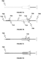
- the orthopedic device is configured as a Polyvinyl alcohol (PVA) sponge 100, as shown in Fig. 1A .
- the sponge is used as framework of backbones molecules to be modified with functional molecules/groups.
- Fig. 1A is a schematic illustration of an example of the structure of a PVA sponge. The illustration shows the carbon chains 102, and OH 104 are the hydroxyl groups that can be replaced with functional groups.
- Fig. 1B shows a magnification image of a PVA sponge.
- the pores diameter is from about 100 microns to about 200 microns.
- the pores diameter may be any size, smaller or larger than the pores appear on Fig. 1B .
- the chains are randomly oriented. In some embodiments, the chains are aligned.
- a methyl methacrylate molecule is used as the functional group that will substitute the PVA in the sponge.
- some hydroxylic groups of the PVA nucleophilicly attack the carboxyilic carbone of methacrylic anhydride (MAH) molecule, resulting in substitution of the hydroxyl group with methyl-methacrylate to produce the poly(vinyl alcohol co methacrylate): P(VAcoMA).
- the P(VAcoMA) is used to attract the methy-methacrylate solution and cause its absorption into the sponge.
- the MMA is polymerized to PMMA, as shown in Fig. 3 .
- the structural modification and curing process is as depicted, for example, in Figs. 4A-E .
- the structure of the PVA sponge is as illustrated, for example in Fig. 4A .
- the structure of the poly(vinyl-alcohol co methacrylate) sponge (P(VAcoMA) sponge) is as illustrated, for example in Fig. 4B .
- MMA molecules occupy the spaces in the sponge and are "stuck" to the methacrylic (MA) groups of the sponge, and the structure of the sponge is, for example, as shown in Fig. 4C .
- MMA molecules are covalently bound one to each other and to the MA groups of the sponge resulting in one bulk of PMMA, providing a partial MMA absorbed P(VAcoMA), and the structure of the sponge is, for example, as shown in Fig. 4D .
- the structure of the sponge is, for example, as shown in Fig. 4E .
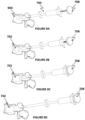
- the methacrylate (MA) sponge 500 having a carbon network of PVA 502 is compressed and dried 550 until hardened prior to implantation, as shown for example, in Figs. 5A-B . In some embodiments, this allows insertion of the implant sponge via a minimally invasive or percutaneous procedure.
- the compressed sponge 550 is placed at the target implantation void 552, as shown for example, in Fig. 5C .
- a small amount of biocompatible solution e.g. saline
- an initiator solution is injected into the expanded sponge generating bonds 556 between methacrylate groups, resulting in a cured hardened polymethacrylate structure, as shown for example, in Fig. 5E .
- the implant comprises a porous architecture which allows the passage of liquids.
- the liquids are responsible for hydrating the implant and bring it from a compressed and dried configuration to an expanded configuration.
- the liquids are responsible for curating the implant.
- the implant comprises a surface texture that allows the implant to be better embedded in the site of implantation.
- the implant can have a predetermined shape.
- the implant is cut to the desired shape using regular tools (e.g. scissors, knifes, etc.).
- the implant is expanded inside external molds, and once curated, can be implanted in specific sites. For example, this technique can be used to shape bone plates for skulls or shape specific bone fragments.
- compositions of curable implant are provided.
- a curable implant according to any of the respective embodiments described herein comprises a polymer cross-linked by a first cross-link, the polymer comprising functional groups capable of cross-linking with each other to form a second cross-link (which functional groups are referred to herein interchangeably as "cross-linkable functional groups").
- curable implants may be obtained using cross-linked PVA as the polymer, with methacrylate functional groups attached to the PVA which are capable of cross-linking with each other (e.g., in the presence of an initiator solution) to form polymerized methacrylate as a second cross-link.
- the polymer comprised by the implant may comprise any suitable polymer known in the art, for example, a biocompatible polymer.
- suitable polymers include, without limitation, poly(vinyl alcohol) (PVA), polyvinylamine (PVM), poly(vinyl chloride), fluoropolymers, polyesters, polyurethanes, polyureas, silicones, and copolymers thereof.
- PVA poly(vinyl alcohol)
- PVM polyvinylamine
- PV chloride poly(vinyl chloride)
- fluoropolymers polyesters, polyurethanes, polyureas, silicones, and copolymers thereof.
- fluoropolymers include, without limitation, polytetrafluoroethylene (PTFE), poly(vinylidene difluoride) (PVDF), polychlorotrifluoroethylene (PCTFE), and poly(vinyl fluoride) (PVF).
- PTFE polytetrafluoroethylene
- PVDF poly(vinylidene difluoride)
- PCTFE polychlorotrifluoroethylene
- PVF poly(vinyl fluoride)
- the polymer is poly(vinyl alcohol) (PVA) of a copolymer thereof, for example, poly(vinyl alcohol-co-ethylene), poly(vinyl alcohol-co-vinyl acetate), poly(vinyl alcohol-co-methyl methacrylate), poly(vinyl alcohol-co-vinyl butyral), poly(vinyl alcohol-co-vinyl chloride), a block copolymer of poly(vinyl alcohol) and poly(ethylene oxide), or a copolymer thereof (e.g., poly(vinyl alcohol-co-vinyl butyral-co-vinyl acetate) or poly(vinyl alcohol-co-vinyl acetate-co-vinyl chloride), which may be regarded as copolymers of poly(vinyl alcohol-co-vinyl acetate) with poly(vinyl alcohol-co-vinyl butyral) or poly(vinyl alcohol-co-vinyl alcohol-co-vinyl
- the polymer optionally comprises one or more species of backbone units, such as, e.g., vinyl alcohol, vinylamine, vinyl chloride, vinyl fluoride, binylidene difluoride, chlorotrifluoroethylene, ethylene, vinyl acetate, methyl methacrylate, vinyl butyral, and/or ethylene oxide backbone units, as this term is defined herein.
- backbone units such as, e.g., vinyl alcohol, vinylamine, vinyl chloride, vinyl fluoride, binylidene difluoride, chlorotrifluoroethylene, ethylene, vinyl acetate, methyl methacrylate, vinyl butyral, and/or ethylene oxide backbone units, as this term is defined herein.
- the polymer has is a cross-linked polymer having formula I: [X]m[X(-L-Y)]n[X-Z-]p Formula I wherein:
- backbone unit refers to a repeating unit, which optionally comprises a side chain (as defined herein), wherein linkage of a plurality of the repeating unit (e.g., sequential linkage) forms a polymeric backbone, optionally with side chains attached to the backbone.
- backbone of a polymer refers to a chain of atoms which is formed by linking repeating units (backbone units) to one another to form the polymer, further including hydrogen atoms and oxo groups attached to the chain (whereas other groups attached to the chain of atoms are referred to as side chains).
- L and Y together form a pendant group of at least a portion of the backbone units, which group is referred to herein for brevity simply as the "pendant group".
- Each backbone unit with a pendant group according to any of the respective embodiments described herein e.g., a unit represented by X(-L-Y) in formula I, the number of which is represented by the variable n
- each backbone unit without a pendant group according to any of the respective embodiments described herein e.g., a unit represented solely by X in formula I, the number of which is represented by the variable m
- each backbone unit attached to first cross-link according to any of the respective embodiments described herein e.g., a unit represented by X attached to Z in formula I, the number of which is represented by the variable p
- a backbone unit refers to a repeating portion of a monomeric unit, which includes (but is not limited to) the portion which forms a polymeric backbone.
- a backbone unit according to any of the respective embodiments described herein may optionally be a residue of a polymerizable monomer or polymerizable moiety of a monomer.
- a wide variety of polymerizable monomers and moieties will be known to the skilled person, and the structure of the residues of such monomers which result upon polymerization (e.g., monomeric units) will also be known to the skilled person.
- a “residue of a polymerizable monomer” refers to a modified form of a polymerizable monomer and/or a portion of a polymerizable monomer that remains after polymerization.
- a portion of a polymerizable monomer may be formed, for example, by a condensation reaction, e.g., wherein at least one atom or group (e.g., a hydrogen atom or hydroxyl group) in the monomer, and optionally at least two atoms or groups (e.g., a hydrogen atom and a hydroxyl group) in the monomer, is replaced with a covalent bond with another polymerizable monomer.
- a condensation reaction e.g., wherein at least one atom or group (e.g., a hydrogen atom or hydroxyl group) in the monomer, and optionally at least two atoms or groups (e.g., a hydrogen atom and a hydroxyl group) in the monomer, is replaced with a covalent bond with another polymerizable monomer.
- a modified form of a polymerizable monomer may be formed, for example, by ring-opening (wherein a covalent bond between two atoms in a ring is broken, and the two atoms optionally each become linked to another polymerizable monomer); and/or by adding to an unsaturated bond, wherein an unsaturated bond between two adjacent atoms is broken (e.g., conversion of an unsaturated double bond to a saturated bond, or conversion of an unsaturated triple bond to an unsaturated double bond) and the two atoms optionally each become linked to another polymerizable monomer.
- a modified form of a polymerizable monomer may consist essentially of the same atoms as the original monomer, for example, different merely in the rearrangement of covalent bonds, or alternatively, may have a different atomic composition, for example, wherein polymerization includes a condensation reaction (e.g., as described herein).
- a modified form of a polymerizable monomer may optionally be modified following polymerization, for example, by cleavage of a side chain.
- poly(vinyl alcohol) and copolymers thereof are commonly prepared by polymerizing vinyl acetate (because vinyl alcohol per se is not readily polymerizable) to obtain poly)vinyl acetate) or a copolymer thereof, and then some or all of the acetate groups to obtain vinyl alcohol backbone units (optionally in combination with remaining vinyl acetate backbone units).
- Vinyl alcohol backbone units may also be formed, for example, by (partial or complete) nucleophilic substitution of a side chain (e.g., chloride in a vinyl chloride unit) by hydroxide.
- backbone units include, without limitation, substituted or unsubstituted hydrocarbons (which may form a substituted or unsubstituted hydrocarbon backbone), such as alkylene units; hydroxycarboxylic acid units (which may form a polyester backbone), e.g., glycolate, lactate, hydroxybutyrate, hydroxyvalerate, hydroxycaproate and hydroxybenzoate units; dicarboxylic acid units (which may form a polyester backbone in combination with a diol and/or a polyamide in combination with a diamine), e.g., adipate, succinate, terephthalate and naphthalene dicarboxylic acid units; diol units (which may form a polyether backbone, or form a polyester backbone in combination with a dicarboxylic acid), e.g., ethylene glycol, 1,2-propanediol, 1,3-propanediol, 1,4-butanediol, and
- the polymer comprises backbone units (e.g., X in formula I) which are a substituted or unsubstituted alkylene unit.
- the polymer comprises backbone units (e.g., X in formula I) which are a substituted or unsubstituted ethylene unit, that is, an alkylene unit 2 atoms in length.
- backbone units e.g., X in formula I
- Such polymerization is a very well-studied procedure, and one of ordinary skill in the art will be aware of numerous techniques for effecting such polymerization.
- any embodiments described herein relating to a polymers formed by a polymerization encompass any polymers having a structure which can be formed by such polymerization, regardless of whether the polymer was formed in practice by such polymerization (or any other type of polymerization).
- the unsaturated bond of ethylene and substituted ethylene derivatives becomes saturated upon polymerization, such that the carbon bonds in the polymeric backbone are saturated, although they may be referred to as units of an unsaturated compound (e.g., a "vinyl monomer” or "olefin monomer”) to which they are analogous.
- an unsaturated compound e.g., a "vinyl monomer” or "olefin monomer
- Polymers which can be formed from unsaturated monomers such as vinyl monomers and olefin monomers are also referred to by the terms "polyvinyl” and "polyolefin”.
- an "unsubstituted" alkylene unit refers to an alkylene unit which does not have any substituent other than the pendant group discussed herein (represented as (-L-Z)). That is, an alkylene unit attached to the aforementioned pendant group is considered unsubstituted if there are no substituents at any other positions on the alkylene unit.
- the polymer comprises backbone units (e.g., X in formula I) having formula II (wherein R 1 -R 3 and A are as defined herein): -CR 1 R 2 -CR 3 A- Formula II
- A is a side chain, such as R 4 (as defined herein); and when the backbone unit (e.g., X) is attached to L, Y or Z, A is a covalent bond or a linking group (as defined herein) attaching to L, Y or Z, thus forming a side chain comprising A, L and Y, or A and Z.
- the linking group may optionally be -O-, -S-, alkylene, arylene, cycloalkyl, heteralicyclic, amine, sulfate, sulfonate, sulfonyl, sulfoxide, phosphate, phosphonyl, phosphinyl, alkoxy, aryloxy, thioalkoxy, thioaryloxy, azo, sulfonamide, carbonyl, thiocarbonyl, carboxy, carbonyl, thiocarbonyl, urea, thiourea, carbamyl, thiocarbamyl, amide, epoxide or amino.
- R 1 -R 4 are each independently hydrogen, alkyl, alkenyl, alkynyl, cycloalkyl, aryl, heteroaryl, heteroalicyclic, amine, halide, sulfate, sulfonate, sulfonyl, sulfoxide, phosphate, phosphonyl, phosphinyl, hydroxy, alkoxy, aryloxy, thiohydroxy, thioalkoxy, thioaryloxy, cyano, nitro, azo, azide, sulfonamide, carbonyl, thiocarbonyl, carboxy, thiocarbamate, urea, thiourea, carbamate, amide, epoxide and hydrazine end groups (as defined herein).
- linking group describes a group (e.g., a substituent) that is attached to two or more moieties in the compound.
- end group describes a group (e.g., a substituent) that is attached to a single moiety in the compound via one atom thereof.
- the backbone unit e.g., X
- R 1 -R 3 is hydrogen, and A is a covalent bond or linking group
- the backbone unit e.g., X
- X is an unsubstituted ethylene unit attached (via A) to a pendant group or first cross-link described herein.
- the backbone unit e.g., X
- X is an unsubstituted ethylene unit which is not attached to a pendant group or first cross-link described herein.
- R 1 and R 2 are each hydrogen.
- Such embodiments include polymeric backbones formed from many widely used vinyl monomers (including ethylene), including, for example, olefins (e.g., ethylene, propylene, 1-butylene, isobutylene, 4-methyl-1-pentene), vinyl chloride, styrene, vinyl acetate, acrylonitrile, acrylate and derivatives thereof (e.g., acrylate esters, acrylamides), and methacrylate and derivatives thereof (e.g., methacrylate esters, methacrylamides).
- olefins e.g., ethylene, propylene, 1-butylene, isobutylene, 4-methyl-1-pentene
- vinyl chloride e.g., ethylene, propylene, 1-butylene, isobutylene, 4-methyl-1-pentene
- vinyl chloride e.g., ethylene, propylene, 1-butylene, isobutylene,
- R 3 is hydrogen. In some such embodiments, R 1 and R 2 are each hydrogen.
- R 3 is methyl.
- R 1 and R 2 are each hydrogen.
- the backbone unit is a unit of methacrylate or a derivative thereof (e.g., methacrylate ester, methacrylamide).
- A is -O-.
- a vinyl alcohol derivative e.g., an ester or ether of a vinyl alcohol unit
- a vinylamine derivative e.g., an amide or substituted amine of a vinylamine unit
- an acrylate or methacrylate derivative e.g., an ester of an
- a backbone unit substituted by a pendant group described herein (according to any of the respective embodiments) - e.g., X attached to L-Y in formula I - may be the same as or different than the backbone unit which is not substituted by the pendant group (e.g., X which is not attached to L-Y in formula I, when m is at least 1).
- the plurality of backbone units substituted by a pendant group (according to any of the respective embodiments) - e.g., X attached to L-Y in formula I - may be the same as each other or different from each other.
- the plurality of pendant groups attached to a plurality of backbone units-e.g., L-Y in formula I - may be the same as each other or different from each other (e.g., may differ in the identity of L and/or Y.
- the plurality of backbone units not substituted by a pendant group (according to any of the respective embodiments) - e.g., X which is not attached to L-Y in formula I - may be the same as each other or different from each other.
- a copolymer described herein may comprise both unsubstituted vinyl alcohol backbone units and additional unsubstituted backbone units (e.g., vinyl acetate, vinyl chloride, etc.), in addition to monomeric units comprising a cross-linkable functional group (e.g., as a substituted vinyl alcohol unit).
- the number of types of monomeric units comprising a cross-linkable functional group may each independently be any number (e.g., 1, 2, 3, 4, 5, 6, 7, 8, 9, 10 or more).
- any two or more different types of monomeric unit may be distributed randomly or non-randomly throughout the polymer.
- the copolymer may be one characterized by any non-random distribution, for example, an alternating copolymer, a periodic copolymer, and/or a block copolymer.
- cross-linkable groups according to any of the respective embodiments described herein may be any cross-linkable group known in the art, and may be attached to any suitable polymer (according to any of the embodiments described herein in the section relating to the polymer).
- the cross-linkable functional groups are capable of cross-linking with each other via polymerization (e.g., wherein curing of the implant comprises effecting polymerization), for example, via fee radical polymerization and/or anionic polymerization.
- Polymerization is optionally effected by contact with a suitable liquid (e.g., an aqueous solution), optionally a solution comprising an initiator (e.g., a free radical initiator, and/or an anionic polymerization initiator such as a nucleophile), and optionally a photoinitiator, which may be activated by illumination (UV and/or visible illumination).
- a suitable liquid e.g., an aqueous solution
- an initiator e.g., a free radical initiator, and/or an anionic polymerization initiator such as a nucleophile
- a photoinitiator which may be activated by illumination (UV and/or visible illumination).
- polymerization is inhibited by storage under dry conditions, and
- polymerizable functional groups are particularly suitable for cross-linking a substance in vivo, without causing excessive irritation to tissue.
- the cross-linkable functional groups are comprised by a pendant group attached to the polymer (e.g., a pendant group represented by the variables L and Y in formula I, according to any of the respective embodiments described herein), that is, they form a side chain (wherein the functional group is attached directly to the polymeric backbone) or a portion of a side chain of the polymer (wherein the functional group is attached to the polymeric backbone via one or more linking group, optionally including -O- or -NH-), rather than form the backbone of the polymer.
- the position of a cross-linkable functional group as a pendant group facilitates cross-linking between backbones.
- a pendant group may optionally be attached directly to the polymeric backbone or to a linking group comprised by a backbone unit in the polymer (according to any of the respective embodiments described herein), for example, a linking group represented by A in formula II, according to any to the respective embodiments described herein.
- a functional group may optionally be attached directly to the polymer (e.g., to the polymeric backbone or to a linking group comprised by a backbone unit).
- the functional group is optionally attached to the polymer via a linking moiety, for example, wherein a pendant group comprises the functional group (e.g., Y in formula I) and the linking moiety (e.g., L in formula I), according to any of the respective embodiments described herein.
- the linking moiety may optionally be attached directly to the polymeric backbone or to a linking group comprised by a backbone unit in the polymer (according to any of the respective embodiments described herein), for example, a linking group represented by A in formula II, according to any to the respective embodiments described herein.
- the linking moiety is optionally selected to facilitate attachment of the functional group to the polymer.
- -CH 2 -CH(OH)-CH 2 -O- and/or -CH 2 -CH(OH)-CH 2 -NR 5 - are optionally obtained by attaching the functional group or polymer to glycidol (e.g., via an ester, ether, amine or amide linking group), and then attaching the polymer or functional group (respectively) to the epoxide group of glycidol (e.g., via attack by a nucleophilic group, such as hydroxy or amine).
- a compound comprising an isocyanate group e.g., via an ester, ether, amine or amide linking group
- polymerizable functional groups e.g., acryl, methacryl, cyanoacryl and vinylsulfonyl
- acryl, methacryl, cyanoacryl and vinylsulfonyl will generally form dimeric, trimeric, oligomeric and/or polymeric moieties formed upon polymerization of the polymerizable functional group.
- the first cross-link may comprise any suitable linking group capable of attaching to two polymeric backbones, preferably by covalent bonds, for example, a residue of a molecule capable of attaching to two different atoms.
- cross-links may be characterized as residues of compounds, for example, residues of a cross-linking agents or structurally related similar compound.
- cross-links which may be incorporated in a polymer according to any of the respective embodiments described herein (in combination with cross-linkable functional groups according to any of the respective embodiments described herein) include, without limitation, formaldehyde residues, dialdehyde residues, dicarboxylic acid residues, diepoxide residues, and diisocyanate residues.
- dialdehyde refers to a molecule having at least two aldehyde groups, as defined herein.
- a dialdehyde residue may optionally comprise at least two acetal, imine and/or hydrazone linking groups which each attach to a polymeric backbone (e.g., via direct attachment to a backbone carbon atom).
- dicarboxylic acid refers to a molecule having at least two carboxylic acid groups, as defined herein.
- a dicarboxylic acid residue may optionally comprise at least two ester and/or amide linking groups which each attach to a polymer backbone (e.g., via direct attachment to a backbone carbon atom).
- diepoxide refers to a molecule having at least two epoxide groups, as defined herein.
- suitable diepoxides include, without limitation, diepoxypropane, diepoxybutane (a.k.a. butadiene diepoxide), diepoxyoctane, and ether diepoxides such as diglycidyl ether.
- a hydroxyalkyl linking group e.g., -CHOH-CH 2 - or -CH(CH 2 OH)-
- a diepoxide residue may optionally comprise at least two hydroxyalkyl linking groups (e.g., -CHOH-CH 2 - and/or -CH(CH 2 OH)-) which each attach to a polymer backbone, optionally via a nucleophilic group such as a nitrogen or oxygen atom (e.g., a nitrogen or oxygen atom directly attached to a backbone carbon atom).
- diisocyanate refers to a molecule having at least two isocyanate groups, as defined herein.
- a carbamate linking group (as defined herein) is optionally formed, and upon reaction of an isocyanate group with an amine group, a urea linking group (as defined herein) is optionally formed.
- a diisocyanate residue may optionally comprise at least two carbamate and/or urea linking groups which each attach to a polymer backbone (e.g., via direct attachment to a backbone carbon atom).
- the properties of the polymer may optionally be controlled by selecting suitable side chains, functional groups and/or first cross-links (according to any of the respective embodiments described herein) and/or suitable proportions thereof.
- an average molecular weight of side chains (including first cross-links) in the polymer is no more than 50 Da. In some such embodiments, the average molecular weight is no more than 45 Da. In some embodiments, the average molecular weight is no more than 40 Da. In some embodiments, the average molecular weight is no more than 35 Da. In some embodiments, the average molecular weight is no more than 30 Da. In some embodiments, the average molecular weight is no more than 25 Da. In some embodiments, the average molecular weight is no more than 20 Da.
- a low average molecular weight may optionally be affected both by low molecular weight of individual side chains (e.g., 17 Da for hydroxyl groups in PVA) as well as by a low proportion of side chains with a higher molecular weight (e.g., functional groups capable of cross-linking with each other, which are optionally large, yet present in only a minority of side chains in the polymer).
- a weight ratio of side chains to backbone in the polymer is no more than 3:1 (side chain: backbone). In some such embodiments, the weight ratio is no more than 2.5:1 (side chain: backbone). In some embodiments, the weight ratio is no more than 2:1 (side chain: backbone). In some embodiments, the weight ratio is no more than 1.5:1 (side chain: backbone). In some embodiments, the weight ratio is no more than 1:1 (side chain: backbone).
- a weight ratio of side chains to backbone may optionally be affected both by an average molecular weight of individual side chains (e.g., according to any of the respective embodiments described herein) as well as by a proportion of side chains, for example, whether the polymer comprises one side chain per monomeric unit (e.g., as in monosubstituted vinyl residues such as vinyl alcohol, vinylamine, vinyl acetate and vinyl chloride residues) or multiple side chains per monomeric unit (e.g., as in tetrafluoroethylene or vinylidene difluoride residues).
- monomeric unit e.g., as in monosubstituted vinyl residues such as vinyl alcohol, vinylamine, vinyl acetate and vinyl chloride residues
- multiple side chains per monomeric unit e.g., as in tetrafluoroethylene or vinylidene difluoride residues.
- a relatively low proportion of first cross-link in the uncured implant is suitable for maintaining integrity of the implant (e.g., by inhibiting dissolution) while allowing flexibility of the uncured polymer.
- an amount of the first cross-link (according to any of the respective embodiments described herein) in the polymer is at least 1 cross-link per 100,000 monomeric units, optionally at least 1 cross-link per 30,000 monomeric units, optionally at least 1 cross-link per 10,000 monomeric units, optionally at least 1 cross-link per 3,000 monomeric units, and optionally at least about 1 cross-link per 1,000 monomeric units.
- an amount of the first cross-link (according to any of the respective embodiments described herein) in the polymer is at least 0.2 cross-links per 1 MDa of the polymer (i.e., at least 1 cross-link per 5 MDa), optionally at least 0.5 cross-links per 1 MDa of the polymer, optionally at least 2 cross-links per 1 MDa of the polymer, optionally at least 5 cross-links per 1 MDa of the polymer, and optionally at least 20 cross-links per 1 MDa of the polymer.
- an amount of the first cross-link (according to any of the respective embodiments described herein) in the polymer is no more than 1 cross-link per 100 monomeric units of the polymer, for example, in a range of from 1 cross-link per 100,000 monomeric units to 1 cross-link per 100 monomeric units, from 1 cross-link per 30,000 monomeric units to 1 cross-link per 100 monomeric units, from 1 cross-link per 10,000 monomeric units to 1 cross-link per 100 monomeric units, from 1 cross-link per 3,000 monomeric units to 1 cross-link per 100 monomeric units, from 1 cross-link per 1,000 monomeric units to 1 cross-link per 100 monomeric units, or about 1 cross-link per 1,000 monomeric units.
- an amount of the first cross-link (according to any of the respective embodiments described herein) in the polymer is no more than 1 cross-link per 300 monomeric units of the polymer, for example, in a range of from 1 cross-link per 100,000 monomeric units to 1 cross-link per 300 monomeric units, from 1 cross-link per 30,000 monomeric units to 1 cross-link per 300 monomeric units, from 1 cross-link per 10,000 monomeric units to 1 cross-link per 300 monomeric units, from 1 cross-link per 3,000 monomeric units to 1 cross-link per 300 monomeric units, or from 1 cross-link per 1,000 monomeric units to 1 cross-link per 300 monomeric units.
- an amount of the first cross-link (according to any of the respective embodiments described herein) in the polymer is no more than 1 cross-link per 1,000 monomeric units of the polymer, for example, in a range of from 1 cross-link per 100,000 monomeric units to 1 cross-link per 1,000 monomeric units, from 1 cross-link per 30,000 monomeric units to 1 cross-link per 1,000 monomeric units, from 1 cross-link per 10,000 monomeric units to 1 cross-link per 1,000 monomeric units, or from 1 cross-link per 3,000 monomeric units to 1 cross-link per 1,000 monomeric units.
- an amount of the first cross-link (according to any of the respective embodiments described herein) in the polymer is no more than 200 cross-links per 1 MDa of the polymer, for example, in a range of from 0.2 to 200 cross-links per 1 MDa of the polymer (i.e., from 1 cross-link per 5 MDa to 1 cross-link per 5 kDa), from 0.5 to 200 cross-links per 1 MDa of the polymer, from 2 to 200 cross-links per 1 MDa of the polymer, from 5 to 200 cross-links per 1 MDa of the polymer, from 20 to 200 cross-links per 1 MDa of the polymer, or about 20 cross-links per 1 MDa of the polymer.
- an amount of the first cross-link (according to any of the respective embodiments described herein) in the polymer is no more than 50 cross-links per 1 MDa of the polymer, for example, in a range of from 0.2 to 50 cross-links per 1 MDa of the polymer, from 0.5 to 50 cross-links per 1 MDa of the polymer, from 2 to 50 cross-links per 1 MDa of the polymer, from 5 to 50 cross-links per 1 MDa of the polymer, or from 20 to 50 cross-links per 1 MDa of the polymer.
- an amount of the first cross-link (according to any of the respective embodiments described herein) in the polymer is no more than 20 cross-links per 1 MDa of the polymer, for example, in a range of from 0.2 to 20 cross-links per 1 MDa of the polymer, from 0.5 to 20 cross-links per 1 MDa of the polymer, from 2 to 20 cross-links per 1 MDa of the polymer, or from 5 to 20 cross-links per 1 MDa of the polymer.
- an amount of cross-linkable functional groups is greater than an amount of first cross-links, that is, the polymer comprises more than 1 cross-linkable functional group per first cross-link in the polymer.
- first cross-links and second cross-links are associated with a considerable change in physical properties upon curing, e.g., because of the proportionally large increase in the number of cross-links in the polymer.
- the polymer comprises at least 3 cross-linkable functional groups per first cross-link in the polymer. In some embodiments, the polymer comprises at least 10 cross-linkable functional groups per first cross-link. In some embodiments, the polymer comprises at least 30 cross-linkable functional groups per first cross-link. In some embodiments, the polymer comprises at least 100 cross-linkable functional groups per first cross-link. In some embodiments, the polymer comprises at least 300 cross-linkable functional groups per first cross-link. In some embodiments, the polymer comprises no more than 10,000, or no more than 1,000 cross-linkable functional groups per first cross-link, for example, from 10 to 1,000 functional groups per first cross-link, or from 30 to 300 functional groups per first cross-link.
- the polymer comprises less cross-linkable functional groups than monomeric units, that is, only a portion of the monomeric units of the polymer comprise a cross-linkable functional group.
- the other monomeric units may optionally lack a side chain (e.g., ethylene residues) or comprise a small side chain (e.g., -OH, -NH 2 , halo), which is optionally selected for providing a flexible uncured polymer (e.g., as described herein).
- an amount of cross-linkable functional group (according to any of the respective embodiments described herein) in the polymer is no more than 50 cross-linkable functional groups per 100 monomeric units of the polymer, optionally no more than 40 cross-linkable functional groups per 100 monomeric units, optionally no more than 30 cross-linkable functional groups per 100 monomeric units, optionally no more than 25 cross-linkable functional groups per 100 monomeric units, optionally no more than 20 cross-linkable functional groups per 100 monomeric units, optionally no more than 15 cross-linkable functional groups per 100 monomeric units, optionally no more than 10 cross-linkable functional groups per 100 monomeric units, and optionally no more than 5 cross-linkable functional groups per 100 monomeric units.
- an amount of cross-linkable functional group (according to any of the respective embodiments described herein) in the polymer is at least 1 cross-linkable functional groups per 100 monomeric units of the polymer, for example, from 1 to 30, from 1 to 25, from 1 to 20, from 1 to 15, from 1 to 10, or from 1 to 5 cross-linkable functional groups per 100 monomeric units.
- an amount of cross-linkable functional group in the polymer is at least 3 cross-linkable functional groups per 100 monomeric units of the polymer, for example, from 3 to 30, from 3 to 25, from 3 to 20, from 3 to 15, or from 3 to 10 cross-linkable functional groups per 100 monomeric units.
- an amount of cross-linkable functional group in the polymer is at least 10 cross-linkable functional groups per 100 monomeric units of the polymer, for example, from 10 to 30, from 10 to 25, from 10 to 20, or from 10 to 15 cross-linkable functional groups per 100 monomeric units. In some embodiments, an amount of cross-linkable functional group in the polymer is about 10 cross-linkable functional groups per 100 monomeric units.
- the proportion of cross-linkable functional groups in the polymer is determined relative to the molecular weight of the polymer (including the functional groups thereof).
- an amount of cross-linkable functional group (according to any of the respective embodiments described herein) in the polymer is no more than 6,000 cross-linkable functional groups per 1 MDa of the polymer (i.e., 6 groups per 1 kDa), optionally no more than 4,000 cross-linkable functional groups per 1 MDa of the polymer, optionally no more than 2,000 cross-linkable functional groups per 1 MDa of the polymer, optionally no more than 1,000 cross-linkable functional groups per 1 MDa of the polymer, optionally no more than 600 cross-linkable functional groups per 1 MDa of the polymer, optionally no more than 400 cross-linkable functional groups per 1 MDa of the polymer, and optionally no more than 200 cross-linkable functional groups per 1 MDa of the polymer.
- an amount of cross-linkable functional group (according to any of the respective embodiments described herein) in the polymer is at least 200 cross-linkable functional groups per 1 MDa of the polymer, for example, from 200 to 6,000, from 200 to 4,000, from 200 to 2,000, from 200 to 1,000, from 200 to 600, or from 200 to 400 cross-linkable functional groups per 1 MDa of the polymer.
- an amount of cross-linkable functional group in the polymer is at least 400 cross-linkable functional groups per 1 MDa of the polymer, for example, from 400 to 6,000, from 400 to 4,000, from 400 to 2,000, or from 400 to 1,000 cross-linkable functional groups per 1 MDa.
- an amount of cross-linkable functional group in the polymer is at least 600 cross-linkable functional groups per 1 MDa of the polymer, for example, from 600 to 6,000, from 600 to 4,000, from 600 to 2,000, or from 600 to 1,000 cross-linkable functional groups per 1 MDa. In some embodiments, an amount of cross-linkable functional group in the polymer is at least 1,000 cross-linkable functional groups per 1 MDa of the polymer, for example, from 1,000 to 6,000, from 1,000 to 4,000, from 1,000 to 2,000, or about 2,000 cross-linkable functional groups per 1 MDa.
- hydrocarbon describes an organic moiety that includes, as its basic skeleton, a chain of carbon atoms, substituted mainly by hydrogen atoms.
- the hydrocarbon can be saturated or non-saturated, be comprised of aliphatic, alicyclic or aromatic moieties, and can optionally be substituted by one or more substituents (other than hydrogen).
- a substituted hydrocarbon may have one or more substituents, whereby each substituent group can independently be, for example, cycloalkyl, alkenyl, alkynyl, aryl, heteroaryl, heteroalicyclic, amine, halide, sulfate, sulfonate, sulfonyl, sulfoxide, phosphate, phosphonyl, phosphinyl, hydroxy, alkoxy, aryloxy, thiohydroxy, thioalkoxy, thioaryloxy, oxo, cyano, nitro, azo, azide, sulfonamide, carbonyl, thiocarbonyl, carboxy, thiocarbamate, urea, thiourea, carbamate, amide, epoxide and hydrazine.
- the hydrocarbon can be an end group or a linking group, as these terms are defined herein.
- the hydrocarbon moiety has 1 to 20 carbon atoms.
- a numerical range e.g., "1 to 20”
- the group, in this case the alkyl group may contain 1 carbon atom, 2 carbon atoms, 3 carbon atoms, etc., up to and including 20 carbon atoms.
- alkyl describes a saturated aliphatic hydrocarbon end group, as defined herein, including straight chain and branched chain groups.
- the alkyl group has 1 to 20 carbon atoms. More preferably, the alkyl is a medium size alkyl having 1 to 10 carbon atoms. Most preferably, unless otherwise indicated, the alkyl is a lower alkyl having 1 to 4 carbon atoms.
- the alkyl group may be substituted or unsubstituted.
- Substituted alkyl may have one or more substituents, whereby each substituent group can independently be, for example, cycloalkyl, alkenyl, alkynyl, aryl, heteroaryl, heteroalicyclic, amine, halide, sulfate, sulfonate, sulfonyl, sulfoxide, phosphate, phosphonyl, phosphinyl, hydroxy, alkoxy, aryloxy, thiohydroxy, thioalkoxy, thioaryloxy, cyano, nitro, azo, azide, sulfonamide, carbonyl, thiocarbonyl, carboxy, thiocarbamate, urea, thiourea, carbamate, amide, epoxide and hydrazine.
- substituent group can independently be, for example, cycloalkyl, alkenyl, alkynyl, aryl, heteroaryl, heteroalicycl
- alkylene describes a saturated or unsaturated aliphatic hydrocarbon linking group, as this term is defined herein, which differs from an alkyl group (when saturated) or an alkenyl or alkynyl group (when unsaturated), as defined herein, only in that alkylene is a linking group rather than an end group.
- alkenyl describes an unsaturated aliphatic hydrocarbon end group which comprises at least one carbon-carbon double bond, including straight chain and branched chain groups.
- the alkenyl group has 2 to 20 carbon atoms. More preferably, the alkenyl is a medium size alkenyl having 2 to 10 carbon atoms. Most preferably, unless otherwise indicated, the alkenyl is a lower alkenyl having 2 to 4 carbon atoms.
- the alkenyl group may be substituted or unsubstituted.
- Substituted alkenyl may have one or more substituents, whereby each substituent group can independently be, for example, cycloalkyl, alkynyl, aryl, heteroaryl, heteroalicyclic, amine, halide, sulfate, sulfonate, sulfonyl, sulfoxide, phosphate, phosphonyl, phosphinyl, hydroxy, alkoxy, aryloxy, thiohydroxy, thioalkoxy, thioaryloxy, cyano, nitro, azo, azide, sulfonamide, carbonyl, thiocarbonyl, carboxy, thiocarbamate, urea, thiourea, carbamate, amide, epoxide and hydrazine.
- substituent group can independently be, for example, cycloalkyl, alkynyl, aryl, heteroaryl, heteroalicyclic, amine, halide,
- alkynyl describes an unsaturated aliphatic hydrocarbon end group which comprises at least one carbon-carbon triple bond, including straight chain and branched chain groups.
- the alkynyl group has 2 to 20 carbon atoms. More preferably, the alkynyl is a medium size alkynyl having 2 to 10 carbon atoms. Most preferably, unless otherwise indicated, the alkynyl is a lower alkynyl having 2 to 4 carbon atoms.
- the alkynyl group may be substituted or unsubstituted.
- Substituted alkynyl may have one or more substituents, whereby each substituent group can independently be, for example, cycloalkyl, alkenyl, aryl, heteroaryl, heteroalicyclic, amine, halide, sulfate, sulfonate, sulfonyl, sulfoxide, phosphate, phosphonyl, phosphinyl, hydroxy, alkoxy, aryloxy, thiohydroxy, thioalkoxy, thioaryloxy, cyano, nitro, azo, azide, sulfonamide, carbonyl, thiocarbonyl, carboxy, thiocarbamate, urea, thiourea, carbamate, amide, epoxide and hydrazine.
- substituent group can independently be, for example, cycloalkyl, alkenyl, aryl, heteroaryl, heteroalicyclic, amine, halide,
- cycloalkyl describes an all-carbon monocyclic or fused ring (i.e., rings which share an adjacent pair of carbon atoms) group where one or more of the rings does not have a completely conjugated pi-electron system.
- the cycloalkyl group may be substituted or unsubstituted.
- Substituted cycloalkyl may have one or more substituents, whereby each substituent group can independently be, for example, alkyl, alkenyl, alkynyl, cycloalkyl, aryl, heteroaryl, heteroalicyclic, amine, halide, sulfate, sulfonate, sulfonyl, sulfoxide, phosphate, phosphonyl, phosphinyl, hydroxy, alkoxy, aryloxy, thiohydroxy, thioalkoxy, thioaryloxy, cyano, nitro, azo, azide, sulfonamide, carbonyl, thiocarbonyl, carboxy, thiocarbamate, urea, thiourea, carbamate, amide, epoxide and hydrazine.
- the cycloalkyl group can be an end group, as this phrase is defined herein, wherein it is attached to a single adjacent
- aryl describes an all-carbon monocyclic or fused-ring polycyclic (i.e., rings which share adjacent pairs of carbon atoms) end group (as this term is defined herein) having a completely conjugated pi-electron system.
- the aryl group may be substituted or unsubstituted.
- Substituted aryl may have one or more substituents, whereby each substituent group can independently be, for example, alkyl, alkenyl, alkynyl, cycloalkyl, aryl, heteroaryl, heteroalicyclic, amine, halide, sulfate, sulfonate, sulfonyl, sulfoxide, phosphate, phosphonyl, phosphinyl, hydroxy, alkoxy, aryloxy, thiohydroxy, thioalkoxy, thioaryloxy, cyano, nitro, azo, azide, sulfonamide, carbonyl, thiocarbonyl, carboxy, thiocarbamate, urea, thiourea, carbamate, amide, epoxide and hydrazine. Phenyl and naphthyl are representative aryl end groups.
- heteroaryl describes a monocyclic or fused ring (i.e., rings which share an adjacent pair of atoms) group having in the ring(s) one or more atoms, such as, for example, nitrogen, oxygen and sulfur and, in addition, having a completely conjugated pi-electron system.
- heteroaryl groups include pyrrole, furan, thiophene, imidazole, oxazole, thiazole, pyrazole, pyridine, pyrimidine, quinoline, isoquinoline and purine.
- the heteroaryl group may be substituted or unsubstituted.
- Substituted heteroaryl may have one or more substituents, whereby each substituent group can independently be, for example, alkyl, alkenyl, alkynyl, cycloalkyl, aryl, heteroaryl, heteroalicyclic, amine, halide, sulfate, sulfonate, sulfonyl, sulfoxide, phosphate, phosphonyl, phosphinyl, hydroxy, alkoxy, aryloxy, thiohydroxy, thioalkoxy, thioaryloxy, cyano, nitro, azo, azide, sulfonamide, carbonyl, thiocarbonyl, carboxy, thiocarbamate, urea, thiourea, carbamate, amide, epoxide and hydrazine.
- substituent group can independently be, for example, alkyl, alkenyl, alkynyl, cycloalkyl, aryl
- the heteroaryl group can be an end group, as this phrase is defined herein, where it is attached to a single adjacent atom, or a linking group, as this phrase is defined herein, connecting two or more moieties.
- Representative examples are pyridine, pyrrole, oxazole, indole, purine and the like.
- arylene describes a monocyclic or fused-ring polycyclic linking group, as this term is defined herein, and encompasses linking groups which differ from an aryl or heteroaryl group, as these groups are defined herein, only in that arylene is a linking group rather than an end group.
- heteroalicyclic describes a monocyclic or fused ring group having in the ring(s) one or more atoms such as nitrogen, oxygen and sulfur.
- the rings may also have one or more double bonds. However, the rings do not have a completely conjugated pi-electron system.
- the heteroalicyclic may be substituted or unsubstituted.
- Substituted heteroalicyclic may have one or more substituents, whereby each substituent group can independently be, for example, alkyl, alkenyl, alkynyl, cycloalkyl, aryl, heteroaryl, heteroalicyclic, amine, halide, sulfate, sulfonate, sulfonyl, sulfoxide, phosphate, phosphonyl, phosphinyl, hydroxy, alkoxy, aryloxy, thiohydroxy, thioalkoxy, thioaryloxy, cyano, nitro, azo, azide, sulfonamide, carbonyl, thiocarbonyl, carboxy, thiocarbamate, urea, thiourea, carbamate, amide, epoxide and hydrazine.
- substituent group can independently be, for example, alkyl, alkenyl, alkynyl, cycloalkyl, ary
- the heteroalicyclic group can be an end group, as this phrase is defined herein, where it is attached to a single adjacent atom, or a linking group, as this phrase is defined herein, connecting two or more moieties.
- Representative examples are piperidine, piperazine, tetrahydrofuran, tetrahydropyran, morpholine and the like.
- amine and “amino” describe both a -NRxRy end group and a -NRx- linking group, wherein Rx and Ry are each independently hydrogen, alkyl, cycloalkyl, aryl, heteroaryl or heteroalicyclic, as these terms are defined herein.
- Rx or Ry is heteroaryl or heteroalicyclic
- the amine nitrogen atom is bound to a carbon atom of the heteroaryl or heteroalicyclic ring.
- the amine group can therefore be a primary amine, where both Rx and Ry are hydrogen, a secondary amine, where Rx is hydrogen and Ry is alkyl, cycloalkyl, aryl, heteroaryl or heteroalicyclic, or a tertiary amine, where each of Rx and Ry is independently alkyl, cycloalkyl, aryl, heteroaryl or heteroalicyclic.
- hydroxy and "hydroxyl” describe a -OH group.
- alkoxy describes both an -O-alkyl and an -O-cycloalkyl end group, or -O-alkylene or -O-cycloalkyl linking group, as defined herein.
- aryloxy describes both an -O-aryl and an -O-heteroaryl end group, or an -O-arylene- linking group, as defined herein.
- thiohydroxy describes a -SH group.
- thioalkoxy describes both an -S-alkyl and an -S-cycloalkyl end group, or -S-alkylene or -S-cycloalkyl linking group, as defined herein.
- thioaryloxy describes both an -S-aryl and an -S-heteroaryl end group, or an - S-arylene- linking group, as defined herein.
- nitro describes an -NO 2 group.
- halide and "halo" refer to fluorine, chlorine, bromine or iodine.
- phosphinyl refers to a -PRxR Y group, where Rx and R Y are as defined hereinabove.
- hydrazine describes a -NRx-NRyRw end group or -NRx-NRy- linking group, with Rx, Ry, and Rw as defined herein.
- epoxide describes a end group or a linking group, as these phrases are defined herein, where Rx, Ry and Rw are as defined herein.
- the curable implant comprises, in some embodiments, a modified polymer comprising cross-linkable functional groups.
- the implant may therefore optionally be cured by cross-linking the cross-linkable functional groups of the polymer per se.
- one or more additional cross-linking agents may be added to the implant, for example, shortly before or during curing (e.g., as part of a solution injected into the implant), such that the polymer becomes cross-linked by both the cross-linkable functional groups of the polymer and the additional cross-linking agent.
- the additional cross-linking agent(s) may comprise any suitable cross-linking agent known in the art.
- the skilled person will understand which cross-linking agents are suitable for cross-linking any given modified polymer, considering the functionalities of the modified polymer.
- the additional cross-linking agent may comprise, for example, a polymerizable monomer as defined herein (e.g., according to any of the respective embodiments described herein).
- the polymerizable monomer(s) may optionally be a monomer from which at least a portion of the monomeric units of the polymer of the implant are derived (e.g., a vinyl monomer in embodiments wherein the polymer comprises vinyl derivatives as monomeric units), and/or a monomer corresponding to the cross-linkable functional group (e.g., a methacrylate monomer such as methyl methacrylate, in embodiments wherein the cross-linkable functional group comprises methacryl).
- the second cross-link obtained upon cross-linking is optionally formed by copolymerization of cross-linkable functional groups in the polymer and in the additional cross-linking agent.
- the additional cross-linking agent comprises a cross-linkable functional group (as described herein), optionally the same cross-linkable functional groups as in the modified polymer.
- the additional cross-linking agent may optionally be a monomer corresponding to the cross-linkable functional group (e.g., as described hereinabove); or alternatively, a compound comprising at least two cross-linkable functional groups (e.g., acryl, methacryl, cyanoacryl, or vinylsulfonyl) connected by a linking moiety, for example, a hydrocarbon moiety, or an alkylene glycol (e.g., ethylene glycol or propylene glycol) residue, or dimer, trimer, oligomer or polymer of an alkylene glycol (e.g., a polyethylene glycol moiety), or connected to a nanoparticle or microparticle.
- a linking moiety for example, a hydrocarbon moiety, or an alkylene glycol (e.g., ethylene glycol or propylene glycol) residue, or dimer, trimer, oligomer or polymer of an alkylene glycol (e.g., a polyethylene glycol moiety
- the additional cross-linking agent is a compound comprising at least two cross-linkable functional groups (optionally the same cross-linkable functional groups as in the polymer) connected by a linking moiety, for example, a hydrocarbon moiety, or an alkylene glycol (e.g., ethylene glycol or propylene glycol) residue, or dimer, trimer, oligomer or polymer of an alkylene glycol (e.g., a polyethylene glycol moiety), or connected to a nanoparticle or microparticle.
- a linking moiety for example, a hydrocarbon moiety, or an alkylene glycol (e.g., ethylene glycol or propylene glycol) residue, or dimer, trimer, oligomer or polymer of an alkylene glycol (e.g., a polyethylene glycol moiety), or connected to a nanoparticle or microparticle.
- the sponge is optionally made from methacrylic polymer containing methacrylic side groups.
- the sponge is made of open porous in different size and shape.
- a potential advantage is to have larger size of porous at the center of the sponge than the size of the porous at the edge of the sponge.
- the sponge is compressed and optionally stabilized by dehydration, as shown for example in Fig. 6A .
- the sponge 600 is optionally immersed in a volatile solution containing initiator for polymerization (e.g. benzoyl peroxide in acetone).
- the distribution of the initiator within the sponge is not homogenous.
- the immersed sponge 600 is then dried.
- the sponge 600 is then slightly absorbed in a solution with no or low solubility to the initiator.
- the sponge 600 is then dried and shrinked to a small size optionally using vacuum. The final size and shape of the dry and hardened sponge was optionally shaped to fit to implantation.
- the shrinked sponge 600 is implanted, for example in a fractured vertebra 610, as shown, for example in Fig. 6B .
- the sponge 600 is attached to needle 620 prior to insertion into the vertebra.
- the needle 620 is connected to syringe 622.
- the syringe 622 is filled with an acrylic monomers or oligomers solution.
- a catalyst is also added to the solution.
- the solution contains a softener material that is used to soften the hardened sponge 600.
- sponge 600 is connected to needle 620, attached to filled syringe 622, is inserted into fractured vertebra 610, as shown for example in Fig. 6B .
- the sponge 600 is inserted into the fractured vertebra 610 prior to connecting to the needle 620.
- more than one sponge 600 is inserted to a single fractured vertebra.
- a solution is first injected into the sponge 600.
- the solution causes the hardened sponge to be softened and expand 640, as shown, for example in Fig. 6C .
- the sponge is filled with the acrylic solution injected from the attached syringe 622.
- the sponge porous are filled with the solution and a polymerization process occurs between the monomers or oligomers and the acrylic groups of the sponge.
- the polymerization is initiated by the initiator that was prior attached to the sponge.
- a single solid material is made.
- the solution filled in syringe 622 is directly injected into the dry and hardened sponge 600.
- the sponge 600 is simultaneously softened, filled with the acrylic solution and polymerized.
- the syringe 622 and needle 620 are then removed living the implanted sponge 640 in the vertebra.
- the curing process is performed by radiating UV to the implant, as shown for example in Fig. 6D .
- the curing process is performed by radiating heat to the implant, as shown for example in Fig. 6E .
- the sponge is delivered to the specific location using a dedicated implant delivery device.
- the delivery device 700 is pre-loaded with the compressed, and optionally dry, implant 702 (see Fig. 7B ).
- the delivery device 700 comprises an inlet port 704 for filling the delivery device 700 with any kind of liquid (e.g. saline, initiator, uncured cement - 720 in Fig. 7C ).
- the delivery device 700 comprises an outlet port 706 to allow purging and release of excess of liquids or cement after the delivery device is filled.
- the delivery device 700 comprises a knob 708 which is used to deliver the implant 702 throughout outlet 710.
- the implant 702 is squeezed into delivery tube 712.
- a dedicated part 714 is attached to the implant 702 and connected to rod 716.
- the other side of rod 716 is connected to piston 718.
- the piston 718 can be moved by rotating knob 708.
- the rotating knob 708 causes part 714 to advance towards outlet 710.
- the part 714 pushes implant 702 out of the delivery tube 712.
- the piston 718 is positioned before inlet 704 and outlet 706.
- the delivery device 700 can be filled with any kind of liquid or uncured cement 720 through inlet port 704.
- Fig. 7C it is shown, for example, the delivery device 700 in the configuration described on Fig. 7B , after the liquids or the uncured cement 720 was filled through inlet port 704.
- the delivery device 700 is preferably held vertically and the liquids or uncured cement 720 is filled until excessive content reaches outlet port 706.
- Fig. 7D it is shown, for example, the delivery device 700, after set-up and in a ready to deliver configuration.
- knob 708 was rotated until piston 718 passed inlet 704 and outlet 706.
- implant 702 is advanced towards outlet 710.
- the implant 702 and liquid or cement 720 are now ready to be delivered.
- Fig. 7E it is shown, for example, the delivery device 700 during the implant 702 delivery. In some embodiments, this procedure is done after the delivery device 700 was positioned in the delivery target site. In some embodiments, optionally the delivery procedure is a minimally invasive procedure. In some embodiments, knob 708 is rotated and pushes the piston 718 that pushes the liquid or uncured cement 720 enabling the implant 702 to absorb the liquids or cement while exiting the delivery device 700 and swelling. In some embodiments, the extruded part of the implant 702 volume increases because of liquid of cement absorption and/or elastic properties. In some embodiments, in this configuration only part of the implant 702 is delivered.
- the delivery device 700 is optionally designed in differences between the piston syringe 722 and the delivery tube 712 cross-section areas. In some embodiments, this is done to deliver larger or smaller volume of liquid or uncured cement 720 compared to the volume of the implant 702 that is released. In some embodiments, this enables the supply of required volume of liquid or uncured cement that is absorbed by the implant throughout the procedure.
- Fig. 7F it is shown, for example, the delivery device 700 after knob 708 was fully rotated. In some embodiments, in this configuration implant 702 is completely released throughout port 710.
- Fig. 7F it is shown, for example, the delivery device 700 after implant 702 was delivered and delivery device 700 is detached from implant 702. In some embodiments, the delivery device 700 is removed and the implant 702 is left in the target site. In some embodiments, the liquids or uncured cement, cure the implant, forming a solid implant.
- Fig. 8 it is shown, for example, an illustrative view of some optional shapes of the implants 702.
- implant 702 can be implemented in any required size and shape before and after implant.
- the quantity of liquids or cement, required for the complete curing of the implant is from about 0.5ml to about 10ml.
- the quantity of liquids or cement, required for the complete curing of the implant is from about 1% to about 10% of the total weight of the implant. In some embodiments, the quantity of liquids or cement, required for the complete curing of the implant is from about 100% to about 300% of the total weight of the implant.
- the quantity of liquids or cement used for the complete curing of the implant is modified according to: the void volume of implantation site and/or the final desired density of the implant and/or the final required stiffness and/or the desired rate of curing and/or the application.
- the time for the curing process with liquid is from about 2 minutes to about 30 minutes for 80% of curing. In some embodiments, the time for the curing process with liquid is from about 5 minutes to about 20 minutes for 80% of curing. In some embodiments, the time for the curing process with liquid is from about 7 minutes to about 10 minutes for 80% of curing.
- the time for the curing process with liquid is from about 1 hour to about 8 hours for 100% of curing. In some embodiments, the time for the curing process with liquid is from about 2 hour to about 6 hours for 100% of curing. In some embodiments, the time for the curing process with liquid is from about 3 hour to about 4 hours for 100% of curing.
- the curing of the delivered implant is performed by exposing the implant to ultraviolet (UV) radiation.
- UV radiation e.g. dimethoxy-diphenyl-ethan-one or benzophenone
- photoinitiator e.g. dimethoxy-diphenyl-ethan-one or benzophenone
- UV light 254 - 350nm
- the radicals would start a chain reaction between the methacrylic groups to form crosslinking network.
- the radiation of the implant can be achieved by inserting optic fiber to the implantation site.
- the time for the curing process with UV is from about 2 seconds to about 3 minutes for 80% of curing. In some embodiments, the time for the curing process with UV is from about 10 seconds to about 2 minutes for 80% of curing. In some embodiments, the time for the curing process with UV is from about 30 seconds to about 1 minutes for 80% of curing.
- the time for the curing process with UV is from about 1 hour to about 8 hours for 100% of curing. In some embodiments, the time for the curing process with UV is from about 2 hour to about 6 hours for 100% of curing. In some embodiments, the time for the curing process with UV is from about 3 hour to about 4 hours for 100% of curing.
- the curing of the delivered implant is performed by exposing the implant to specific temperatures.
- a thermal initiator e.g. Azobis[2-(2-imidazolin-2-yl)propane]dihydrochloride
- the implant is heated at a temperature from about 40 degrees Celsius to about 60 degrees Celsius.
- the temperature of the heating is from about 45 degrees Celsius to about 55 degrees Celsius.
- the heating will produce free radicals in the sponge. The radicals would start a chain reaction between the methacrylic groups to form crosslinking network.
- the heating of the implant can be achieved by inserting heating probe to the implantation site.
- the time for the curing process with heat is from about 2 minutes to about 30 minutes for 80% of curing. In some embodiments, the time for the curing process with heat is from about 5 minutes to about 20 minutes for 80% of curing. In some embodiments, the time for the curing process with heat is from about 7 minutes to about 10 minutes for 80% of curing.
- the time for the curing process with heat is from about 1 hour to about 8 hours for 100% of curing. In some embodiments, the time for the curing process with heat is from about 2 hour to about 6 hours for 100% of curing. In some embodiments, the time for the curing process with heat is from about 3 hour to about 4 hours for 100% of curing.
- the implant in its soft configuration comprises the following characteristics:
- the implant comprises in order to introduce directionally to the implant.
- the sponge can be produce by layers instead of as one bulk. In this case after crosslinking and hardening of the sponge it will receive different elasticity in different directions
- porosity or void fraction is a measure of the void (i.e. "empty") spaces in the material, and is a fraction of the volume of voids over the total volume, between 0 and 1, or as a percentage between 0% and 100%.
- the porosity percentage (%) from about 60% to about 100%. In some embodiments, the porosity percentage is from about 70% to about 90%. In some embodiments, the porosity percentage is from about 75% to about 85%. In some embodiments, different porosity is achieved by controlling the density of the cross-linker at different regions of the implant and by using different wetting agents in the foaming stage of the implant production. In some embodiments, the implant is produced by layers instead of one bulk. This will enable non-homogenous distribution of the porous in the sponge, that is, different concentration and porous sizes at different sites.
- the pore size (um): is from about 50 um to about 3000 um. In some embodiments, the pore size (um): is from about 100 um to about 2000 um. In some embodiments, the pore size (um): is from about 500 um to about 1000 um.
- the density (g/cm 3 ): is from about 0.05 g/cm 3 to about 0.5 g/cm 3 . In some embodiments, the density (g/cm 3 ): is from about 0.1 g/cm 3 to about 0.4 g/cm 3 . In some embodiments, the density (g/cm 3 ): is from about 0.1 g/cm 3 to about 0.2 g/cm 3 .
- the elastic modulus (MPa): is from about 0.001 MPa to about 1 MPa. In some embodiments, the elastic modulus (MPa): is from about 0.01 MPa to about 0.1 MPa. In some embodiments, the elastic modulus (MPa): is from about 0.05 MPa to about 0.1 MPa. In some embodiments, the elastic modulus is selected according to the specific site to which will be implanted. In some embodiments, different elasticity is achieved by controlling the density of the cross-linker at different regions of the implant. In some embodiments, at high density, the implant is characterized by a higher modulus of elasticity and vice versa. In some embodiments, the implant is produced by layers instead of one bulk. This will enable controlling the direction of elasticity so that the final hardened implant will have higher elasticity in one direction and lower in another.
- the implant in its hard (or stiff) configuration comprises the following characteristics:
- the porosity percentage (%) from about 60% to about 100%. In some embodiments, the porosity percentage is from about 70% to about 90%. In some embodiments, the porosity percentage is from about 75% to about 85%.
- the pore size (um): is from about 50 um to about 3000 um. In some embodiments, the pore size (um): is from about 100 um to about 2000 um. In some embodiments, the pore size (um): is from about 500 um to about 1000 um.
- the density (g/cm 2 ): is from about 0.05 g/cm 2 to about 0.5 g/cm 2 . In some embodiments, the density (g/cm 2 ): is from about 0.1 g/cm 2 to about 0.4 g/cm 2 . In some embodiments, the density (g/cm 2 ): is from about 0.1 g/cm 2 to about 0.2 g/cm 2 .
- the elastic modulus (MPa): is from about 1 MPa to about 500 MPa. In some embodiments, the elastic modulus (MPa): is from about 2 MPa to about 150 MPa. In some embodiments, the elastic modulus (MPa): is from about 5 MPa to about 100 MPa.
- Figs. 9A to 9D are an illustrative view of a procedure according to some embodiments, applied with this invention.
- a Vertebroplasty or Kyphoplasy procedure is shown on Fig. 9A .
- a fractured vertebra 900 is shown on Fig. 9A .
- the delivery device 700 is inserted, optionally in a trans-pedicular procedure through cannula 902.
- the implant is optionally introduced after creating a void using a Kyphoplasty balloon, or with no prior void creation, during Vertebroplasty procedure.
- the delivery device 700 and implant 702 are in the configuration described on Fig.7D .
- the delivery device is introduced to the target site.
- FIG. 9B shows the delivery device 700 and implant 702 in the configuration described on Fig. 7E , after knob 708 was partly rotated and part of the implant 702 is delivered and expanded.
- Fig. 9C shows the delivery device 700 and implant 702 in the configuration described on Fig. 7F , after knob 708 was fully rotated and implant 702 is completely delivered.
- Fig. 9D is an illustrative view of the delivery device 700 and cannula 902, after removal from the treated vertebra via completion of implant 702 delivery, according to some embodiments.
- the implant 702 is placed in the target site at the fractured vertebrae.
- the implant 702 is expanded to its final shape or in the shape determined by the vertebrae anatomy.
- the uncured implant is cured to a solid structure.
- Figs. 10A to 10D are an illustrative view of one alternative procedure applied with some embodiments of this invention.
- a fixation of non-displaced or impacted femoral neck fractures is shown.
- this procedure is optionally done percutaneously.
- the delivery device 700 in configuration described on Fig. 7D is inserted to a fractured femoral 1000 in a direct lateral approach, optionally through a cannula (not shown).
- the delivery device outlet 710 is optionally positioned distal to fracture 1002.
- Fig 10B shows the delivery device 700 and implant 702 after knob 708 was rotated and implant 702 was partially delivered.
- FIG. 10C shows the delivery device 700 and implant 702 after knob 708 was fully rotated and implant 702 is placed in the target site.
- the implant 702 is positioned in-between the fracture 1002 portions to generate robust fixture.
- Fig. 10D shows the delivery device 700 after removal from the fractured femoral 1000.
- the implant 702 is expanded to its final shape or in the shape determined by the vertebrae anatomy.
- the implant is cured to a solid structure.
- additional support and rotational stability is done by screws placement before or after this procedure.
- Fig. 11A is a side view of a bone 1100 having numerous fractures 1102. In some embodiments, these types of fractures are treated with implanted nails and or plates and screws.
- Fig. 11B schematically shows the use of the implant 702 to treat a bone having multiple fractures. In some embodiments, the implant 702 is positioned inside the fractured bone 1100. Optionally, additional implants e.g. plates and screws are used.
- Fig. 12 shows a bone 1200 that is not fractured or having only micro fractures.
- the bone 1200 is in a risk of fracture because of osteoporotic or other causes.
- the implant 702 is implanted and thereby strengthens the bone and reduces the risk for future fracture.
- the biocompatible soft sponge implant having the ability to harden following initiation, is used in various applications in the medical field.
- each of the following applications comprises a potential advantage over state of the art solutions.
- the human skeleton is composed of 270 bones at birth. Any of these bones may suffer a fracture during its lifetime. Fractures may be caused due to traumatic incidents or due to medical conditions that weaken the bone, such as osteoporosis or bone cancer. In some cases, it is the combination of a weak bone and a minor trauma that causes a fracture.
- a reduction and stabilization procedure is done. Different techniques are used to stabilize a fractured bone, depends on the bone location, the fracture severity and the procedure chose. In some cases, an external fixation like plaster cast or braces are used. In some cases, metal rods or plates are used to hold the bone pieces together.
- the implant is used as an alternative or in addition to current solutions.
- the implant is inserted into a fractured bone, optionally, in a minimally invasive percutaneous procedure.
- the implant is inserted as a solid and soft material.
- an initiation process is triggered.
- the implant is hardened and holds the bone fractured pieces in a restored position.
- this solution has the potential for better treatment with less surgical trauma, especially in fractures where access is more limited.
- some examples are; hip fracture, rib fracture and clavicle fracture.
- osteoporosis causes more than 9 million fractures annually. Of which 1.6 million hip fractures, 1.7 million forearm and 1.4 million are vertebral fractures. Bone metastases also cause bone loss and increase the risk for bone fracture.
- a surgical prevention procedure is done with the aim of increasing the resistance of a weak bone e.g. femoral neck to the compression and distraction forces acting on it, though reduce the risk for fracture.
- the first surgical reinforcement of the femoral neck was proposed for the first time in 1960.
- Stainless-steel nails where inserted in a percutaneous procedure, under local anesthesia.
- a more recently approach is called "femoroplasty" consisting of injection of poly-methyl-methacrylate (PMMA) inside osteoporotic femoral neck.
- PMMA poly-methyl-methacrylate
- the implant is used for this application, instead of the current used PMMA, thus eliminating the heat generated.
- the implant is used together with the PMMA, thus reducing the amount of PMMA needed and therefor reducing the heat generated.
- the implant has osteoconductive properties which allow bone growth at the implantation site.
- Xenograft bone substitutes have their origin from a species other than human. Bovine bone is usually used. Some type of corals maybe harvested and treated to become coral based xenografts.
- Ceramics bone substitutes are calcium based substitutes made of Hydroxyapatite and TCP (Tricalcium Phosphate).
- CPC Calcium phosphate cements
- a white powder consisting of calcium phosphate, that when mixed with a liquid, forms a workable paste which can be shaped during surgery to fit the contours of bone loss.
- the cements hardening reaction which forms nanocrystalline hydroxyapatite (HA) is isothermic and occurs at physiologic pH so tissue damage does not occur during the setting reaction.
- HA nanocrystalline hydroxyapatite
- Polymer-based bone graft substitutes have physical, mechanical, and chemical properties completely different from the other bone substitutes.
- the polymers can be divided into natural polymers and synthetic polymers. Polymers such as PMMA and various other acrylates are used for their mechanical resilience and biocompatibility.
- the implant is used as bone substitute for filling small gaps as well as large voids.
- the implant in addition to the mechanical strengthening and bone stabilizing, may serve as an osteoconductive scaffold material enabling new bone growth.
- the implant is applied on any bone in the body including bone augmentations for dental applications.
- Techniques involve the drilling of bone tunnels, with or without pull through sutures, or may use fixation of soft tissues to bone using screws and washers.
- Bone fasteners and toggle anchors are sometimes used and require a larger access to the underlying bone with a higher potential for damage during the implant insertion.
- Current designs of bone anchors allow them to be inserted arthroscopically or through a very small per-cutaneous incision.
- Bioabsorbable anchors were developed, having equal pullout strength to the metal anchors.
- Biodegradable polymers were developed and are currently found in modern anchors include poly-L-lactic acid, poly-D, L lactic acid, polydioxanone, polyglycolic acid and their copolymers.
- Acrylic bone cements are also widely used in orthopaedic applications to anchor implants to existing bone.
- anchoring is requires are; Avulsion fractures, Bicipital Tendon Injuries, Collateral Ligament Pathology (Knee), Distal Humerus Fractures, Knee Dislocations, Lateral Epicondylitis, Mannerfelt Syndrome, Meniscal repair, Medial Humeral Condyle Fracture, Patellar Tendon Rupture, Perilunate Fracture Dislocations, Posterior Glenohumeral Instability, Quadriceps Tendon Rupture, Recurrent Ankle Sprains, Stener Lesion, Superior Labral Lesions, Superior Labrum Lesions, Triangular Fibrocartilage Complex Injuries and Wrist Arthroscopy.
- the implant is used as an anchoring material, connecting a bone to a soft tissue. In some embodiments, the implant is used as a standalone implant or as an additive to existing solutions.
- Articular cartilage is a connective tissue of diarthrodial joints. Its principal function is to provide a smooth, lubricated surface for articulation and to facilitate the transmission of loads with a low frictional coefficient. Cartilage has limited repair capabilities because chondrocytes are bound in lacunae and cannot migrate to damaged areas. Injury or diseases like; Osteoarthritis, Achondroplasia, Costochondritis, Spinal disc herniation, Relapsing polychondritis and Relapsing polychondritis can affect and damage the cartilage.
- Biomaterials currently used for cartilage replacement/regeneration are; Hydrogels like Poly vinyl alcohol (PVA), Polyacrylates, Poly (N-isopropylacrylamide) and Amidated polysaccharide hydrogel.
- PVA Poly vinyl alcohol
- Polyacrylates Poly (N-isopropylacrylamide)
- Amidated polysaccharide hydrogel Other materials used are silicon rubber and polymeric composite materials.
- the implant overcomes some of the current limitation of materials used today.
- the implant is applied in a form of sponge like or in a form of a dense material for the use as artificial cartilage or disc.
- the implant used for artificial cartilage or disc applications is placed at the target site, having certain material properties enabling efficient delivery to the target site. Then an initiation process changes its material properties to fit to the artificial implant requirements.
- an arthrodesis surgery also known as artificial ankylosis may be done.
- a bone graft and/or instruments are used to encourage bone growth over the joint and create one immobile unit. Joint fusion can effectively reduce pain. This procedure is most commonly performed on joints in the spine, hand, ankle, and foot.
- a bone graft can be placed between the two bones using a bone from elsewhere in the person's body (autograft) or using donor bone (allograft) from a bone bank.
- autograft a bone from elsewhere in the person's body
- autograft donor bone
- allograft donor bone
- synthetic bone substitutes are used. These are usually hydroxyapatite- or tricalcium phosphate-based granules formed into a coralline or trabecular structure to mimic the structure of cancellous bone.
- the bone graft act solely as an osteoconductive matrix.
- metal implants can be attached to the two bones to hold them together in a position which favors bone growth. Sometimes a combination of the above methods is also employed.
- the implant is used in these procedures.
- the implant is placed between two bones, with or without a bone graft, and form an osteoconductive matrix enabling bone growth and fusion.
- the implant may also act as a mechanical fixation together with solid implants or as a standalone implant to eliminate movement and hold the joint in a preferred position.
- Cosmetic implants are used in dentistry, breast augmentation surgeries and face reconstructive surgeries. Cosmetic implants are also used to enhance the shape of buttocks, calf, and pectoral regions. Implants are made of Polymers, Metals, Ceramics, and Biomaterials. Tumor removal, laceration repair, maxillofacial surgery, scar revision and hand surgery are the common reconstruction procedures done by cosmetic implants.
- the implant is used as an implant for cosmetic applications.
- the implant comprises a pre-formed final size and shape or can be shaped by a surgeon at the time and place of surgery.
- the implant is placed under an open surgery or in a minimally invasive procedure, through a small incision.
- the implant is inserted while having material properties enabling the delivery through a small size tube and only after placed at target site, a triggering mechanism changes the implant properties to fit best for the application.
- the implant acts as osteoconductive matrix for cosmetic surgeries were bone additive is needed.
- the implant is in a softer form and serve as a growth substrate for soft tissue.
- Preparation of exemplary curable sponges comprises by two processes: a) attachment of cross-linkable functional groups (e.g., methacrylate) to a polymer (e.g., poly(vinyl alcohol)) to obtain a cross-linkable modified polymer; and b) preparation of a sponge from the polymer (or modified polymer) by further crosslinking with a cross-linker (e.g., formaldehyde) to obtain a cross-linked polymer comprising a first cross-link, wherein cross-linking is optionally effected in the presence of gas bubbles in order to obtain a sponge structure.
- the two processes may optionally be performed sequentially, in any order, or in a concomitantly.
- the product was precipitated by pouring into 1 liter isopropanol, and vigorously mixing with a glass rod.
- the obtained white pellet was filtered, washed a few times with isopropanol, and dried for 12 hours in a vacuum, to yield PVA modified with methacrylate groups.
- the reaction mixture was incubated for 12 hours at 50 °C, and then cooled to room temperature (-25 °C).
- the product was precipitated by pouring into 1 liter isopropanol, and vigorously mixing with a glass rod.
- the obtained white pellet was filtered, washed a few times with isopropanol, and dried for 12 hours in a vacuum, to yield PVA modified with methacrylate groups attached via a carbamate linking group.
- the product was precipitated by pouring into 1 liter of isopropanol and vigorously mixing with a glass rod.
- the obtained white pellet was filtered, washed a few times with isopropanol, and dried for 12 hours in a vacuum, to yield PVA modified with methacrylate groups.
- a fresh 20 % (by weight) solution of formaldehyde was prepared by adding 1 gram paraformaldehyde (33.3 mmol formaldehyde monomers) to 5 ml of distilled water at 60 °C while stirring. 50 ⁇ l of 10 % NaOH solution was added to complete immersion. 5 ml of the previously prepared 15 % P(VAcoMA) solution was added to a 25 ml beaker placed in a cool water bath.
- Triton TM X-405 (alternatively, Triton TM 100, Span TM 20, Tween TM 80, or Pluronic TM F127 were used), and then 1.2 ml of the previously prepared 20 % formaldehyde solution.
- the solution was frothed using a frother for one minute, left for 45 minutes, and then frothed again for one more minute. The frothed solution was left for 24 hours at room temperature.
- the cross-linked product with a sponge structure was removed from the beaker, washed intensively with water, incubated for 2 hours in a sodium bicarbonate solution to neutralize the acidity, and then washed again with water, to yield a PVA sponge with methacrylate groups.
- PVA sponges with methacrylate groups were prepared in a one-step process beginning from non-modified PVA (PVA without methacrylate groups).
- Cross-linking with butadiene diepoxide was effected according to procedures as described hereinabove, except that glycidyl methacrylate was also reacted with the PVA (according to procedures similar to those described in Section A.3 hereinabove), to yield a PVA sponge with methacrylate groups.
- P(VAcoMA) PVA modified with methacrylate groups
- PVA sponges with methacrylate groups were prepared in a one-step process beginning from non-modified PVA (PVA without methacrylate groups).
- Cross-linking with hexamethylene diisocyanate was effected according to procedures as described hereinabove, except that 2-isocyanatoethyl methacrylate was also reacted with the PVA (according to procedures similar to those described in Section A.2 hereinabove), to yield a PVA sponge with methacrylate groups attached via a carbamate linking group.
- cross-linking procedures according to any one of Sections B.1-B.3 is optionally combined with the modification procedures according to any one of Sections A.1-A.3.
- alternative cross-linking rio modification procedures known in the art are optionally used instead of the cross-linking procedures according to any one of Sections B.1-B.3 or the modification procedures according to any one of Sections A.1-A.3, respectively.
- compositions, method or structure may include additional ingredients, steps and/or parts, but only if the additional ingredients, steps and/or parts do not materially alter the basic and novel characteristics of the claimed composition, method or structure.
- a compound or “at least one compound” may include a plurality of compounds, including mixtures thereof.
Landscapes
- Health & Medical Sciences (AREA)
- Chemical & Material Sciences (AREA)
- Life Sciences & Earth Sciences (AREA)
- Animal Behavior & Ethology (AREA)
- Medicinal Chemistry (AREA)
- Oral & Maxillofacial Surgery (AREA)
- Transplantation (AREA)
- Epidemiology (AREA)
- Veterinary Medicine (AREA)
- Dermatology (AREA)
- General Health & Medical Sciences (AREA)
- Public Health (AREA)
- Chemical Kinetics & Catalysis (AREA)
- Dispersion Chemistry (AREA)
- Materials For Medical Uses (AREA)
- Prostheses (AREA)
- Other Resins Obtained By Reactions Not Involving Carbon-To-Carbon Unsaturated Bonds (AREA)
Claims (13)
- Implant de qualité médicale, comprenant une architecture poreuse qui permet le passage de liquides, et un corps déformable formé d'un polymère réticulé par une première réticulation, ledit polymère comprenant des groupes fonctionnels capables de réticuler pour former une seconde réticulation ; ledit corps est fourni dans une première configuration qui est réticulée à une seconde configuration lors de l'application d'un stimulus sélectionné; dans lequel ledit stimulus sélectionné provoque la réticulation desdits groupes fonctionnels.
- Implant selon la revendication 1, dans lequel ledit stimulus est choisi dans le groupe constitué d'un liquide, d'une température, d'un rayonnement ultraviolet (UV) et d'un monomère.
- Implant selon l'une des revendications précédentes, dans lequel, dans la première configuration, l'implant a un module d'élasticité de 0,01 à 1 MPa.
- Implant selon l'une des revendications précédentes, dans lequel, dans la deuxième configuration, ledit dispositif a un module d'élasticité de 2 à 250 MPa.
- Implant selon l'une des revendications précédentes, dans lequel le corps a une structure cellulaire ouverte avec un pourcentage de porosité de 65% à 85%.
- Implant selon l'une des revendications précédentes, dans lequel le polymère a la formule I :
[X]m[X(-L-Y)]n[X-Z-]p Formule I
dans lequel :m est zéro ou un nombre entier positif;n et p sont chacun indépendamment un nombre entier au moins égal à 1, la somme de m, n et p étant au moins égale à 10;X est une unité de squelette qui forme un squelette polymérique ;L est absent ou est un groupement de liaison;Y est ledit groupe fonctionnel ; etZ est la première réticulation,dans lequel L et Y forment ensemble un groupe pendant. - Implant selon l'une des revendications précédentes, dans lequel ledit polymère est choisi dans le groupe constitué par le poly(alcool vinylique) (PVA), la polyvinylamine (PVM), le poly(chlorure de vinyle), un fluoropolymère, un polyester, un polyuréthane, une polyurée, un silicone, et leurs copolymères.
- Implant selon l'une des revendications précédentes, dans lequel le poids moléculaire moyen des chaînes latérales dudit polymère ne dépasse pas 50 Da, et/ou dans lequel le rapport pondéral entre les chaînes latérales et le squelette dudit polymère ne dépasse pas 3:1 (chaîne latérale : squelette).
- Implant selon la revendication 6, dans lequel une quantité de ladite première réticulation dans ledit polymère est comprise entre 1 réticulation pour 100 000 unités monomériques dudit polymère et 1 réticulation pour 100 unités monomériques dudit polymère et/ou entre 0,2 et 500 réticulations pour 1 MDa dudit polymère.
- Implant selon l'une des revendications précédentes, dans lequel ledit groupe fonctionnel est capable de se réticuler par polymérisation.
- Implant selon l'une des revendications précédentes, dans lequel une quantité dudit groupe fonctionnel dans ledit polymère est comprise entre 1 et 30 groupes fonctionnels pour 100 unités monomériques dudit polymère et/ou entre 200 et 6 000 groupes fonctionnels pour 1 MDa dudit polymère.
- Implant selon l'une des revendications précédentes, étant destiné à être utilisé dans le traitement d'un os, ledit traitement comprenant :a. en délivrant au moins l'un des implants de qualité médicale à l'endroit ciblé dans ledit os; etb. stimuler ledit au moins un implant pour provoquer la réticulation du corps dudit au moins un implant d'une première configuration à une seconde configuration;dans laquelle ladite délivrance comprend la délivrance dudit implant dans une configuration comprimée; et dans laquelle ladite stimulation comprend la stimulation dudit au moins un implant pour qu'il s'étende dans l'endroit ciblé.
- Système d'implant de qualité médicale comprenant:a. un implant de qualité médicale selon l'une des revendications 1 à 11;b. un dispositif de livraison d'implant de qualité médicale; etc. au moins un stimulus.
Applications Claiming Priority (3)
| Application Number | Priority Date | Filing Date | Title |
|---|---|---|---|
| US201762481688P | 2017-04-05 | 2017-04-05 | |
| US201762530400P | 2017-07-10 | 2017-07-10 | |
| PCT/IL2018/050402 WO2018185770A1 (fr) | 2017-04-05 | 2018-04-04 | Implant à changement de propriété |
Publications (2)
| Publication Number | Publication Date |
|---|---|
| EP3606568A1 EP3606568A1 (fr) | 2020-02-12 |
| EP3606568B1 true EP3606568B1 (fr) | 2023-07-12 |
Family
ID=62116515
Family Applications (1)
| Application Number | Title | Priority Date | Filing Date |
|---|---|---|---|
| EP18722740.0A Active EP3606568B1 (fr) | 2017-04-05 | 2018-04-04 | Implant à changement de propriété |
Country Status (4)
| Country | Link |
|---|---|
| US (2) | US11426487B2 (fr) |
| EP (1) | EP3606568B1 (fr) |
| CN (1) | CN110709110B (fr) |
| WO (1) | WO2018185770A1 (fr) |
Families Citing this family (7)
| Publication number | Priority date | Publication date | Assignee | Title |
|---|---|---|---|---|
| WO2018185770A1 (fr) | 2017-04-05 | 2018-10-11 | Setbone Medical Ltd. | Implant à changement de propriété |
| US20200262948A1 (en) * | 2019-02-14 | 2020-08-20 | University Of South Carolina | Functionalized Polyvinyl Alcohol and Products Formed Therewith |
| CN114502207A (zh) * | 2019-08-26 | 2022-05-13 | 赛特博恩医疗有限公司 | 包含多种硬化状态的植入物 |
| US20220370679A1 (en) * | 2019-10-03 | 2022-11-24 | University Of North Carolina At Chapel Hill | Injectable and moldable tissue-mimetic elastomers and methods related thereto |
| CA3232456A1 (fr) * | 2021-09-29 | 2023-04-06 | Setbone Medical Ltd. | Ciment osseux acrylique sans monomere et pret a l'emploi ayant des proprietes de durcissement sur site accelerees |
| CN114470324B (zh) * | 2022-02-08 | 2023-04-04 | 福建医科大学附属协和医院 | 通用的骨植入物改性新策略用于伴糖尿病骨缺损的干预 |
| CN115381569A (zh) * | 2022-07-21 | 2022-11-25 | 南方科技大学 | Peek种植体表面改进方法和设备 |
Family Cites Families (26)
| Publication number | Priority date | Publication date | Assignee | Title |
|---|---|---|---|---|
| US2609347A (en) | 1948-05-27 | 1952-09-02 | Wilson Christopher Lumley | Method of making expanded polyvinyl alcohol-formaldehyde reaction product and product resulting therefrom |
| US4670506A (en) | 1985-12-23 | 1987-06-02 | Ciba-Geigy Corporation | Polyvinyl alcohol derivatives containing pendant (meth)acryloyl units bound through urethane groups and crosslinked hydrogel contact lenses made therefrom |
| JP3732404B2 (ja) * | 1998-02-23 | 2006-01-05 | ニーモサイエンス ゲーエムベーハー | 形状記憶ポリマー組成物、形状記憶製品を形成する方法、および形状を記憶する組成物を形成する方法 |
| JP3400740B2 (ja) | 1999-04-13 | 2003-04-28 | 東芝セラミックス株式会社 | リン酸カルシウム系多孔質焼結体およびその製造方法 |
| US6332894B1 (en) | 2000-03-07 | 2001-12-25 | Zimmer, Inc. | Polymer filled spinal fusion cage |
| AUPQ824100A0 (en) | 2000-06-20 | 2000-07-13 | De Toffol, Roberto | A method of manufacturing syntactic foam |
| US6878384B2 (en) * | 2001-03-13 | 2005-04-12 | Microvention, Inc. | Hydrogels that undergo volumetric expansion in response to changes in their environment and their methods of manufacture and use |
| US7329414B2 (en) * | 2002-05-03 | 2008-02-12 | Biopsy Sciences, Llc | Biodegradable polymer for marking tissue and sealing tracts |
| US20040220672A1 (en) | 2003-05-03 | 2004-11-04 | Shadduck John H. | Orthopedic implants, methods of use and methods of fabrication |
| US20060058891A1 (en) * | 2004-09-16 | 2006-03-16 | Lesh Michael D | Transformable tissue bulking device |
| KR100591638B1 (ko) | 2005-12-07 | 2006-06-21 | 주식회사 백산 | 미세기공이 형성된 무용제형 폴리우레탄 발포체 및 이를활용한 인조피혁 제조방법 |
| US7771476B2 (en) | 2006-12-21 | 2010-08-10 | Warsaw Orthopedic Inc. | Curable orthopedic implant devices configured to harden after placement in vivo by application of a cure-initiating energy before insertion |
| JP2009013397A (ja) | 2007-06-04 | 2009-01-22 | Nitto Denko Corp | 熱可塑性樹脂発泡体、およびその製造方法 |
| EP2227212A1 (fr) * | 2007-12-07 | 2010-09-15 | BioCure, Inc. | Substitut osseux |
| IL188740A0 (en) | 2008-01-13 | 2008-12-29 | Efraim Nativ | Composite material and process for the preparation thereof |
| WO2010005992A1 (fr) * | 2008-07-07 | 2010-01-14 | Biomimedica, Inc. | Alliage ipn hydrophile issu de polymères hydrophobes |
| US8182872B2 (en) | 2008-09-25 | 2012-05-22 | Imec | Method of fabricating a porous elastomer |
| AU2009317974A1 (en) | 2008-10-30 | 2010-05-27 | Vanderbilt University | Bone/polyurethane composites and methods thereof |
| JP5465429B2 (ja) | 2008-12-24 | 2014-04-09 | 株式会社Shindo | シリコーンゴムスポンジ形成性エマルション組成物およびシリコーンゴムスポンジの製造方法 |
| CN102272206B (zh) | 2009-01-16 | 2013-10-30 | 日东电工株式会社 | 交联型树脂发泡体、及其制造方法 |
| US9526813B2 (en) * | 2009-07-13 | 2016-12-27 | Yissum Research Development Company Of The Hebrew University Of Jerusalem Ltd. | Intraluminal polymeric devices for the treatment of aneurysms |
| CN101966409B (zh) | 2010-11-05 | 2013-06-19 | 谭明宁 | 一种新型高分子过滤材料及其制备方法 |
| KR101404426B1 (ko) | 2011-12-26 | 2014-06-09 | 제일모직주식회사 | 발포 또는 개방 세포 구조를 갖는 인조대리석용 칩, 이를 포함하는 인조대리석 및 그 제조방법 |
| US10363215B2 (en) | 2013-11-08 | 2019-07-30 | The Texas A&M University System | Porous microparticles with high loading efficiencies |
| CN104922733B (zh) * | 2015-06-19 | 2017-05-03 | 西安理工大学 | 一种可注射膨胀型骨水泥及其制备方法 |
| WO2018185770A1 (fr) | 2017-04-05 | 2018-10-11 | Setbone Medical Ltd. | Implant à changement de propriété |
-
2018
- 2018-04-04 WO PCT/IL2018/050402 patent/WO2018185770A1/fr not_active Ceased
- 2018-04-04 EP EP18722740.0A patent/EP3606568B1/fr active Active
- 2018-04-04 US US16/500,417 patent/US11426487B2/en active Active
- 2018-04-04 CN CN201880037276.3A patent/CN110709110B/zh active Active
-
2022
- 2022-08-29 US US17/897,252 patent/US20230023996A1/en active Pending
Also Published As
| Publication number | Publication date |
|---|---|
| CN110709110A (zh) | 2020-01-17 |
| EP3606568A1 (fr) | 2020-02-12 |
| CN110709110B (zh) | 2023-05-16 |
| US20230023996A1 (en) | 2023-01-26 |
| CA3058726A1 (fr) | 2018-10-11 |
| WO2018185770A1 (fr) | 2018-10-11 |
| US20200139005A1 (en) | 2020-05-07 |
| US11426487B2 (en) | 2022-08-30 |
Similar Documents
| Publication | Publication Date | Title |
|---|---|---|
| US20230023996A1 (en) | Property changing implant | |
| US8715366B2 (en) | Porous and nonporous materials for tissue grafting and repair | |
| US20090240337A1 (en) | Methods, Devices and Compositions for Adhering Hydrated Polymer Implants to Bone | |
| US20050010297A1 (en) | Balloon technologies for tissue repair | |
| JP2002505592A (ja) | 生体内原位置で組織を修復するのに用いる生体用材料システム | |
| WO2010059389A2 (fr) | Composites os/polyuréthane et procédés associés | |
| WO2011075183A1 (fr) | Composites tissu-polyuréthane injectables/se formant in situ et procédés de préparation associés | |
| US20120041444A1 (en) | Orthopedic surgeries | |
| US20150265745A1 (en) | Porous and Nonporous Materials for Tissue Grafting and Repair | |
| US8663225B2 (en) | Hydrogel bone void filler | |
| US10105207B2 (en) | Porous and nonporous materials for tissue grafting and repair | |
| CA3058726C (fr) | Implant a changement de propriete | |
| US12611483B2 (en) | Implant comprising a plurality of hardening states | |
| RU2224475C2 (ru) | Способ лечения болезни кенига | |
| WO2023168314A1 (fr) | Composite avec copolymère gonflant poreux pour fixation osseuse |
Legal Events
| Date | Code | Title | Description |
|---|---|---|---|
| STAA | Information on the status of an ep patent application or granted ep patent |
Free format text: STATUS: UNKNOWN |
|
| STAA | Information on the status of an ep patent application or granted ep patent |
Free format text: STATUS: THE INTERNATIONAL PUBLICATION HAS BEEN MADE |
|
| PUAI | Public reference made under article 153(3) epc to a published international application that has entered the european phase |
Free format text: ORIGINAL CODE: 0009012 |
|
| STAA | Information on the status of an ep patent application or granted ep patent |
Free format text: STATUS: REQUEST FOR EXAMINATION WAS MADE |
|
| 17P | Request for examination filed |
Effective date: 20191105 |
|
| AK | Designated contracting states |
Kind code of ref document: A1 Designated state(s): AL AT BE BG CH CY CZ DE DK EE ES FI FR GB GR HR HU IE IS IT LI LT LU LV MC MK MT NL NO PL PT RO RS SE SI SK SM TR |
|
| AX | Request for extension of the european patent |
Extension state: BA ME |
|
| DAV | Request for validation of the european patent (deleted) | ||
| DAX | Request for extension of the european patent (deleted) | ||
| STAA | Information on the status of an ep patent application or granted ep patent |
Free format text: STATUS: EXAMINATION IS IN PROGRESS |
|
| 17Q | First examination report despatched |
Effective date: 20210126 |
|
| GRAP | Despatch of communication of intention to grant a patent |
Free format text: ORIGINAL CODE: EPIDOSNIGR1 |
|
| STAA | Information on the status of an ep patent application or granted ep patent |
Free format text: STATUS: GRANT OF PATENT IS INTENDED |
|
| INTG | Intention to grant announced |
Effective date: 20230103 |
|
| GRAS | Grant fee paid |
Free format text: ORIGINAL CODE: EPIDOSNIGR3 |
|
| GRAA | (expected) grant |
Free format text: ORIGINAL CODE: 0009210 |
|
| STAA | Information on the status of an ep patent application or granted ep patent |
Free format text: STATUS: THE PATENT HAS BEEN GRANTED |
|
| AK | Designated contracting states |
Kind code of ref document: B1 Designated state(s): AL AT BE BG CH CY CZ DE DK EE ES FI FR GB GR HR HU IE IS IT LI LT LU LV MC MK MT NL NO PL PT RO RS SE SI SK SM TR |
|
| P01 | Opt-out of the competence of the unified patent court (upc) registered |
Effective date: 20230528 |
|
| REG | Reference to a national code |
Ref country code: CH Ref legal event code: EP |
|
| REG | Reference to a national code |
Ref country code: IE Ref legal event code: FG4D |
|
| REG | Reference to a national code |
Ref country code: DE Ref legal event code: R096 Ref document number: 602018053178 Country of ref document: DE |
|
| REG | Reference to a national code |
Ref country code: LT Ref legal event code: MG9D |
|
| REG | Reference to a national code |
Ref country code: NL Ref legal event code: MP Effective date: 20230712 |
|
| REG | Reference to a national code |
Ref country code: AT Ref legal event code: MK05 Ref document number: 1586407 Country of ref document: AT Kind code of ref document: T Effective date: 20230712 |
|
| PG25 | Lapsed in a contracting state [announced via postgrant information from national office to epo] |
Ref country code: NL Free format text: LAPSE BECAUSE OF FAILURE TO SUBMIT A TRANSLATION OF THE DESCRIPTION OR TO PAY THE FEE WITHIN THE PRESCRIBED TIME-LIMIT Effective date: 20230712 |
|
| PG25 | Lapsed in a contracting state [announced via postgrant information from national office to epo] |
Ref country code: GR Free format text: LAPSE BECAUSE OF FAILURE TO SUBMIT A TRANSLATION OF THE DESCRIPTION OR TO PAY THE FEE WITHIN THE PRESCRIBED TIME-LIMIT Effective date: 20231013 |
|
| PG25 | Lapsed in a contracting state [announced via postgrant information from national office to epo] |
Ref country code: ES Free format text: LAPSE BECAUSE OF FAILURE TO SUBMIT A TRANSLATION OF THE DESCRIPTION OR TO PAY THE FEE WITHIN THE PRESCRIBED TIME-LIMIT Effective date: 20230712 |
|
| PG25 | Lapsed in a contracting state [announced via postgrant information from national office to epo] |
Ref country code: IS Free format text: LAPSE BECAUSE OF FAILURE TO SUBMIT A TRANSLATION OF THE DESCRIPTION OR TO PAY THE FEE WITHIN THE PRESCRIBED TIME-LIMIT Effective date: 20231112 |
|
| PG25 | Lapsed in a contracting state [announced via postgrant information from national office to epo] |
Ref country code: SE Free format text: LAPSE BECAUSE OF FAILURE TO SUBMIT A TRANSLATION OF THE DESCRIPTION OR TO PAY THE FEE WITHIN THE PRESCRIBED TIME-LIMIT Effective date: 20230712 Ref country code: RS Free format text: LAPSE BECAUSE OF FAILURE TO SUBMIT A TRANSLATION OF THE DESCRIPTION OR TO PAY THE FEE WITHIN THE PRESCRIBED TIME-LIMIT Effective date: 20230712 Ref country code: PT Free format text: LAPSE BECAUSE OF FAILURE TO SUBMIT A TRANSLATION OF THE DESCRIPTION OR TO PAY THE FEE WITHIN THE PRESCRIBED TIME-LIMIT Effective date: 20231113 Ref country code: NO Free format text: LAPSE BECAUSE OF FAILURE TO SUBMIT A TRANSLATION OF THE DESCRIPTION OR TO PAY THE FEE WITHIN THE PRESCRIBED TIME-LIMIT Effective date: 20231012 Ref country code: LV Free format text: LAPSE BECAUSE OF FAILURE TO SUBMIT A TRANSLATION OF THE DESCRIPTION OR TO PAY THE FEE WITHIN THE PRESCRIBED TIME-LIMIT Effective date: 20230712 Ref country code: LT Free format text: LAPSE BECAUSE OF FAILURE TO SUBMIT A TRANSLATION OF THE DESCRIPTION OR TO PAY THE FEE WITHIN THE PRESCRIBED TIME-LIMIT Effective date: 20230712 Ref country code: IS Free format text: LAPSE BECAUSE OF FAILURE TO SUBMIT A TRANSLATION OF THE DESCRIPTION OR TO PAY THE FEE WITHIN THE PRESCRIBED TIME-LIMIT Effective date: 20231112 Ref country code: HR Free format text: LAPSE BECAUSE OF FAILURE TO SUBMIT A TRANSLATION OF THE DESCRIPTION OR TO PAY THE FEE WITHIN THE PRESCRIBED TIME-LIMIT Effective date: 20230712 Ref country code: GR Free format text: LAPSE BECAUSE OF FAILURE TO SUBMIT A TRANSLATION OF THE DESCRIPTION OR TO PAY THE FEE WITHIN THE PRESCRIBED TIME-LIMIT Effective date: 20231013 Ref country code: FI Free format text: LAPSE BECAUSE OF FAILURE TO SUBMIT A TRANSLATION OF THE DESCRIPTION OR TO PAY THE FEE WITHIN THE PRESCRIBED TIME-LIMIT Effective date: 20230712 Ref country code: ES Free format text: LAPSE BECAUSE OF FAILURE TO SUBMIT A TRANSLATION OF THE DESCRIPTION OR TO PAY THE FEE WITHIN THE PRESCRIBED TIME-LIMIT Effective date: 20230712 Ref country code: AT Free format text: LAPSE BECAUSE OF FAILURE TO SUBMIT A TRANSLATION OF THE DESCRIPTION OR TO PAY THE FEE WITHIN THE PRESCRIBED TIME-LIMIT Effective date: 20230712 |
|
| PG25 | Lapsed in a contracting state [announced via postgrant information from national office to epo] |
Ref country code: PL Free format text: LAPSE BECAUSE OF FAILURE TO SUBMIT A TRANSLATION OF THE DESCRIPTION OR TO PAY THE FEE WITHIN THE PRESCRIBED TIME-LIMIT Effective date: 20230712 |
|
| REG | Reference to a national code |
Ref country code: DE Ref legal event code: R097 Ref document number: 602018053178 Country of ref document: DE |
|
| PG25 | Lapsed in a contracting state [announced via postgrant information from national office to epo] |
Ref country code: SM Free format text: LAPSE BECAUSE OF FAILURE TO SUBMIT A TRANSLATION OF THE DESCRIPTION OR TO PAY THE FEE WITHIN THE PRESCRIBED TIME-LIMIT Effective date: 20230712 Ref country code: RO Free format text: LAPSE BECAUSE OF FAILURE TO SUBMIT A TRANSLATION OF THE DESCRIPTION OR TO PAY THE FEE WITHIN THE PRESCRIBED TIME-LIMIT Effective date: 20230712 Ref country code: EE Free format text: LAPSE BECAUSE OF FAILURE TO SUBMIT A TRANSLATION OF THE DESCRIPTION OR TO PAY THE FEE WITHIN THE PRESCRIBED TIME-LIMIT Effective date: 20230712 Ref country code: DK Free format text: LAPSE BECAUSE OF FAILURE TO SUBMIT A TRANSLATION OF THE DESCRIPTION OR TO PAY THE FEE WITHIN THE PRESCRIBED TIME-LIMIT Effective date: 20230712 Ref country code: CZ Free format text: LAPSE BECAUSE OF FAILURE TO SUBMIT A TRANSLATION OF THE DESCRIPTION OR TO PAY THE FEE WITHIN THE PRESCRIBED TIME-LIMIT Effective date: 20230712 Ref country code: SK Free format text: LAPSE BECAUSE OF FAILURE TO SUBMIT A TRANSLATION OF THE DESCRIPTION OR TO PAY THE FEE WITHIN THE PRESCRIBED TIME-LIMIT Effective date: 20230712 |
|
| PLBE | No opposition filed within time limit |
Free format text: ORIGINAL CODE: 0009261 |
|
| STAA | Information on the status of an ep patent application or granted ep patent |
Free format text: STATUS: NO OPPOSITION FILED WITHIN TIME LIMIT |
|
| PG25 | Lapsed in a contracting state [announced via postgrant information from national office to epo] |
Ref country code: IT Free format text: LAPSE BECAUSE OF FAILURE TO SUBMIT A TRANSLATION OF THE DESCRIPTION OR TO PAY THE FEE WITHIN THE PRESCRIBED TIME-LIMIT Effective date: 20230712 |
|
| 26N | No opposition filed |
Effective date: 20240415 |
|
| PG25 | Lapsed in a contracting state [announced via postgrant information from national office to epo] |
Ref country code: SI Free format text: LAPSE BECAUSE OF FAILURE TO SUBMIT A TRANSLATION OF THE DESCRIPTION OR TO PAY THE FEE WITHIN THE PRESCRIBED TIME-LIMIT Effective date: 20230712 |
|
| PG25 | Lapsed in a contracting state [announced via postgrant information from national office to epo] |
Ref country code: BG Free format text: LAPSE BECAUSE OF FAILURE TO SUBMIT A TRANSLATION OF THE DESCRIPTION OR TO PAY THE FEE WITHIN THE PRESCRIBED TIME-LIMIT Effective date: 20230712 |
|
| PG25 | Lapsed in a contracting state [announced via postgrant information from national office to epo] |
Ref country code: MC Free format text: LAPSE BECAUSE OF FAILURE TO SUBMIT A TRANSLATION OF THE DESCRIPTION OR TO PAY THE FEE WITHIN THE PRESCRIBED TIME-LIMIT Effective date: 20230712 |
|
| PG25 | Lapsed in a contracting state [announced via postgrant information from national office to epo] |
Ref country code: MC Free format text: LAPSE BECAUSE OF FAILURE TO SUBMIT A TRANSLATION OF THE DESCRIPTION OR TO PAY THE FEE WITHIN THE PRESCRIBED TIME-LIMIT Effective date: 20230712 Ref country code: BG Free format text: LAPSE BECAUSE OF FAILURE TO SUBMIT A TRANSLATION OF THE DESCRIPTION OR TO PAY THE FEE WITHIN THE PRESCRIBED TIME-LIMIT Effective date: 20230712 |
|
| REG | Reference to a national code |
Ref country code: CH Ref legal event code: PL |
|
| PG25 | Lapsed in a contracting state [announced via postgrant information from national office to epo] |
Ref country code: LU Free format text: LAPSE BECAUSE OF NON-PAYMENT OF DUE FEES Effective date: 20240404 |
|
| REG | Reference to a national code |
Ref country code: BE Ref legal event code: MM Effective date: 20240430 |
|
| PG25 | Lapsed in a contracting state [announced via postgrant information from national office to epo] |
Ref country code: LU Free format text: LAPSE BECAUSE OF NON-PAYMENT OF DUE FEES Effective date: 20240404 |
|
| PG25 | Lapsed in a contracting state [announced via postgrant information from national office to epo] |
Ref country code: BE Free format text: LAPSE BECAUSE OF NON-PAYMENT OF DUE FEES Effective date: 20240430 |
|
| PG25 | Lapsed in a contracting state [announced via postgrant information from national office to epo] |
Ref country code: BE Free format text: LAPSE BECAUSE OF NON-PAYMENT OF DUE FEES Effective date: 20240430 Ref country code: CH Free format text: LAPSE BECAUSE OF NON-PAYMENT OF DUE FEES Effective date: 20240430 |
|
| PG25 | Lapsed in a contracting state [announced via postgrant information from national office to epo] |
Ref country code: IE Free format text: LAPSE BECAUSE OF NON-PAYMENT OF DUE FEES Effective date: 20240404 |
|
| PGFP | Annual fee paid to national office [announced via postgrant information from national office to epo] |
Ref country code: DE Payment date: 20250422 Year of fee payment: 8 |
|
| PGFP | Annual fee paid to national office [announced via postgrant information from national office to epo] |
Ref country code: GB Payment date: 20250423 Year of fee payment: 8 |
|
| PGFP | Annual fee paid to national office [announced via postgrant information from national office to epo] |
Ref country code: FR Payment date: 20250425 Year of fee payment: 8 |
|
| PG25 | Lapsed in a contracting state [announced via postgrant information from national office to epo] |
Ref country code: CY Free format text: LAPSE BECAUSE OF FAILURE TO SUBMIT A TRANSLATION OF THE DESCRIPTION OR TO PAY THE FEE WITHIN THE PRESCRIBED TIME-LIMIT; INVALID AB INITIO Effective date: 20180404 |
|
| PG25 | Lapsed in a contracting state [announced via postgrant information from national office to epo] |
Ref country code: HU Free format text: LAPSE BECAUSE OF FAILURE TO SUBMIT A TRANSLATION OF THE DESCRIPTION OR TO PAY THE FEE WITHIN THE PRESCRIBED TIME-LIMIT; INVALID AB INITIO Effective date: 20180404 |
|
| PG25 | Lapsed in a contracting state [announced via postgrant information from national office to epo] |
Ref country code: TR Free format text: LAPSE BECAUSE OF FAILURE TO SUBMIT A TRANSLATION OF THE DESCRIPTION OR TO PAY THE FEE WITHIN THE PRESCRIBED TIME-LIMIT Effective date: 20230712 |