EP3606609B1 - Steuerung der transkraniellen magnetischen stimulation - Google Patents
Steuerung der transkraniellen magnetischen stimulation Download PDFInfo
- Publication number
- EP3606609B1 EP3606609B1 EP18718181.3A EP18718181A EP3606609B1 EP 3606609 B1 EP3606609 B1 EP 3606609B1 EP 18718181 A EP18718181 A EP 18718181A EP 3606609 B1 EP3606609 B1 EP 3606609B1
- Authority
- EP
- European Patent Office
- Prior art keywords
- coil
- energy storage
- coils
- control unit
- magnetic stimulation
- Prior art date
- Legal status (The legal status is an assumption and is not a legal conclusion. Google has not performed a legal analysis and makes no representation as to the accuracy of the status listed.)
- Active
Links
Images




Classifications
-
- A—HUMAN NECESSITIES
- A61—MEDICAL OR VETERINARY SCIENCE; HYGIENE
- A61N—ELECTROTHERAPY; MAGNETOTHERAPY; RADIATION THERAPY; ULTRASOUND THERAPY
- A61N2/00—Magnetotherapy
- A61N2/004—Magnetotherapy specially adapted for a specific therapy
- A61N2/006—Magnetotherapy specially adapted for a specific therapy for magnetic stimulation of nerve tissue
-
- A—HUMAN NECESSITIES
- A61—MEDICAL OR VETERINARY SCIENCE; HYGIENE
- A61N—ELECTROTHERAPY; MAGNETOTHERAPY; RADIATION THERAPY; ULTRASOUND THERAPY
- A61N2/00—Magnetotherapy
- A61N2/02—Magnetotherapy using magnetic fields produced by coils, including single turn loops or electromagnets
Definitions
- the invention concerns in general the technical field of transcranial magnetic stimulation. More particularly, the invention concerns controlling of transcranial magnetic stimulation.
- Transcranial magnetic stimulation is a noninvasive tool for stimulating cortical neurons.
- TMS is used, e.g., for presurgical mapping of functional areas of the cortex, studying the cortical effective connectivity, and treatment of major depression.
- the stimulation is achieved by feeding a brief, strong current pulse through the windings of a coil placed over the subject's scalp. This causes a time-varying magnetic field that induces an electric field in the cortex, resulting in membrane de- and hyperpolarization in the targeted neurons.
- the stimulator coil unit In multichannel TMS (mTMS), the stimulator coil unit consists of several coils that can be controlled independently.
- the electric field (E-field) pattern induced in the brain can be modified by adjusting the current passing through the windings of each individual coil.
- the total E-field is the sum of the E-fields produced by the individual coils, each E-field intensity being proportional to the rate of change of the coil current of the individual coil. Because the E-field determines the site of stimulation, mTMS allows controlling the stimulus location electronically without the need to move the coil unit.
- Such a device is disclosed for example in WO 2009 026 386 .
- the speed by which the stimulus pattern (E-field) can be controlled is a key parameter that determines for what kind of use the device is suitable for. Having the possibility to change the stimulus within approximately a millisecond or several milliseconds is needed in some paradigms.
- a conventional single-channel paired-pulse TMS paradigm two TMS pulses with independently controlled intensities are delivered only 2-5 ms apart.
- an mTMS device should be able to deliver these two pulses in different locations-or even better, be able to deliver an arbitrary pulse train with a desired spatial-temporal pattern.
- the E-field intensity which is proportional to the rate of change of the coil current, is proportional to the voltage of the charge-storage capacitor (or a capacitor bank, consisting of capacitors in parallel and/or in series).
- the voltage levels of the capacitors need to be adjusted quickly.
- the voltage-level adjustment may take from tens of milliseconds up to a few seconds.
- the speed issue is commonly overcome by having two capacitors that can be charged independently before the stimulation: one of the capacitors is used for the first pulse and the other for the second pulse.
- this increases the cost and the size of the device.
- the stimulus locations and intensities may not even be known in advance, e.g., when a feedback-controlled system is in use, making it impractical to fix the capacitor voltages before the pulse sequence.
- a fast, impossible-to-design-in-advance intensity adjustment is needed is the case when the relative movement of the coil and the brain is compensated for by adjusting the coil currents accordingly.
- the conventional solutions have a drawback that the pulse duration depends on the inductance of the coil, which has made it challenging to adapt the stimulus pulse individually.
- the current input to the coil is controlled through a modulated control signal of the power source inputting the current to the coil. In this manner, it is possible to adjust the waveform of the current input to the coil and, hence, the E-field induced in the brain.
- This kind of prior art solutions are still facing the drawbacks as discussed above i.e. they are based on one coil only, and further they are capacitor-coil specific and, as a result, the cost and size of the TMS device remains high.
- transcranial magnetic stimulation device as defined by the respective independent claim.
- a transcranial magnetic stimulation device comprising: at least two coils, an input channel for each coil, a control unit and at least one energy storage for storing energy for the at least two coils
- the control unit is configured to: determine at least one stimulus intensity intended to be generated in the target by generating magnetic field by at least one coil of the at least two coils; determine an energy level stored in the at least one energy storage; determine a modulation pattern for each coil, the modulation pattern being at least in part dependent on an energy level of the at least one energy storage, for generating the magnetic field by the at least one coil of the at least two coils, the generated magnetic field by the at least one coil causing the intended stimulus intensity in the target; generate at least one control signal for controlling the input channel of the at least one coil of the at least two coils according to the determined modulation pattern in order to control a current input of each coil from the at least one energy storage; control the current input of each coil in a step-like manner, wherein a step-like waveform of current
- the at least one energy storage may be arranged in one of the following manner: at least one common energy storage for a plurality of the coils, at least one dedicated energy storage for each coil, at least one common energy storage for a plurality of the coils and at least one dedicated energy storage for each coil, at least one common energy storage for a plurality of coils and at least one dedicated energy storage for at least one coil.
- the at least one energy storage may comprise at least one capacitor.
- the control unit may further be configured to determine the energy level stored in the at least one energy storage by measuring a voltage level of the at least one energy storage.
- the control unit may also be configured to, in response to a detection that the energy level stored in the at least one energy storage is below an energy level needed for generating a magnetic field with the at least one coil causing the intended stimulus intensity in the target with the determined modulation pattern, initiate a charging of the at least one energy storage.
- control unit may be configured to determine the modulation pat-tern for generating a plurality of consecutive magnetic fields with the at least one coil.
- the generated at least one control signal may be configured to control a conductive state of at least one switching device in at least one input channel.
- the switching device may be at least one of the following: insulated-gate bipolar transistor, IGBT; metal-oxide-semiconductor field-effect transistor, MOSFET.
- the control unit may be configured to control the current input of each coil with a pulse-width-modulation-based control signal.
- Figure 1 schematically illustrates at least some aspects of a principle of the present invention applied in a field of a multichannel transcranial magnetic stimulation wherein the stimulator coil unit consists of several coils 130, 140 that can be controlled independently.
- the electric field (E-field) pattern induced in a target may be modified by adjusting the current passing through the windings of each individual coil.
- at least a selection of the coils 130, 140 may be performed by controlling the input channels 150, 160 of the corresponding coils 130, 140 by a control unit 170.
- circuit energy is fed by a power source 110, which is stored in energy storage 120 to be supplied to the coils 130, 140 in a controlled manner.
- the energy storage 120 is, according to invention non-limiting example as illustrated in Figure 1 , common to at least two coils 130, 140.
- Figure 1 is illustrated with two coils 130, 140, but the number of coils is not limited to two.
- the input channels may comprise a number of switching devices on one side or both sides of the coil in question.
- the present invention is at least in part based on an idea that the control unit 170 is configured to determine at least one stimulus intensity to be caused by an electric field induced in a target in response to a generation of the magnetic field by at least one of the coils 130, 140 and control a generation of the magnetic field by the coil 130, 140 in question accordingly.
- the controlling is arranged so that the control unit 170 is configured to determine an energy level of the energy storage 120 dedicated to the coil in question or common to a plurality of coils, or even a combination of these two. The determination may e.g.
- control unit 170 may comprise, or is coupled to, a measurement arrangement by means of which it is possible to measure a voltage of the energy storage or energy storages, such as a capacitor or capacitors, in question. Additionally, the determination may comprise predetermined calculation by means of which the described piece of information may be derived. Moreover, the control unit 170 is configured to determine a modulation pattern for each coil for generating the magnetic field by the at least one coil 130, 140 of the at least two coils 130, 140 wherein the generated magnetic field by the at least one coil causes the intended stimulus intensity in the target. The determination of modulation pattern may also comprise a step of detecting whether the energy storages have necessary amount of energy in order to generate the magnetic field through the modulation.
- control unit may be configured to initiate the charging of the number of energy storages prior to continuing the procedure further.
- the initiation may e.g. comprise a generation a control signal to the power source 110 in order to provide current to the energy storage.
- any controlling to the input channels may be prevented.
- control unit 170 may be configured to obtain a limit set for an energy level to an energy storage or energy storages and to monitor that the limit is reached when the one or more energy storages are charged before enabling to perform the solution according to the present invention.
- control unit may be configured to determine the modulation pattern for generating a plurality of consecutive magnetic fields with the at least one coil 130, 140.
- control unit 170 is configured to generate at least one control signal for controlling the input channel of the at least one coil 130, 140 of the at least two coils 130, 140 according to the determined modulation pattern in order to control an input of each coil 130, 140 from the at least one energy storage 120.
- the generated control signal may be at least in part dependent on the energy level stored in the at least one energy storage and the aim is to generate such an input signal to the coil in question, which causes a generation of the desired stimulus intensity in the target.
- input to the coil 130, 140 in question through the input channel is advantageously in a form of a current pulse which is modulated by the control unit 170 through controlling an input channel 150, 160 accordingly.
- the input channels 150, 160 it is possible to generate an individually modulated input current, i.e. input signal, for each coil 130, 140 and in that manner to control the induced E-field in the target.
- the energy storage 120 may refer to a device, or a plurality of devices coupled to each other, which may store energy.
- the storing of energy may be arranged so that the power source provides electrical energy to the energy storage 120, which electrical energy may be stored through charging of the electrical energy.
- An applicable device for storing energy in the application area may be a charge-storage capacitor, or a capacitor bank, which may be charged and discharged.
- the capacitor, or the plurality of capacitors shall be selected so that their operating parameters meet the need in the application area.
- the energy storage 120 is arranged in the circuit so that it may provide the stored energy to a plurality of coils 130, 140.
- the input channel 150, 160 may comprise a number of switching devices by means of which a coil 130, 140 into which the energy from the energy storage 120 is to be input, but also by means of which the input current pulse may be modulated. In other words, by controlling at least one switch the mentioned effects may be achieved.
- the switching devices belonging to the input channel 150, 160 may e.g. be insulated-gate bipolar transistors (IGBT) which are power semiconductor devices primarily used as an electronic switch.
- IGBT devices One advantage of IGBT devices is that they combine high efficiency and fast switching, which makes them applicable in the area of transcranial magnetic stimulation.
- the controlling of the IGBT is arranged by applying a control voltage to the metal-oxide-semiconductor gate structure, which drives the IGBT to conducting state, or vice versa.
- a control voltage is applied to the metal-oxide-semiconductor gate structure, which drives the IGBT to conducting state, or vice versa.
- MOSFET metal-oxide-semiconductor field-effect transistor
- the input channel 150, 160 may comprise a necessary number of switching devices coupled to each other in a way that the selection of the coils 130, 140 may be achieved as well as the modulation may be performed to the current pulse to be input to the selected coil 130, 140.
- the control unit 170 may refer to a device comprising a processing unit and a memory unit wherein a computer program code is stored in the memory unit.
- the computer program code when executed by the processing unit, generates instructions for controlling an operation of the control unit 170, and hence the device for stimulating the target with a magnetic field generated by the coil, or coils.
- the control unit 170 may also store instructions regarding the magnetic field(s) to be generated with the device, i.e. with the coils belonging to the device.
- the information regarding the magnetic fields may be pre-stored in the memory or be generated e.g. in response to a feedback signal obtained e.g. from the target for which the magnetic field is generated for inducing the electric field in the target.
- the feedback signal may be obtained by monitoring electric currents in brain in response to the induction of the electric field in the target, and in response to that to generate information, or instructions, in the control unit 170.
- the feedback signal may be obtained by monitoring an electrical activity of one or more muscles in response to inducing the electric field in a target as described.
- the feedback signal in such an implementation may e.g. be obtained with an electromyography or with applicable acceleration sensors position on a target surface.
- the control unit 170 thus, generates a control signal for selecting a coil 130, 140, and for modulating the signal to be input to the selected coil 130, 140 in order to achieve a desired effect in the target.
- the control unit 170 may receive its power from a power source and may comprise further elements and/or units coupled to it, such as a measurement device for obtaining information on an energy level of at least one energy storage. These are not described in more detail in this context.
- FIG. 2 it is disclosed an example of an implementation of the device on a component level.
- the device as depicted in Figure 2 comprises a power source 110 for providing electrical energy for energy storage 120, which in the implementation of Figure 2 is a capacitor C.
- the capacitor is coupled with respect to coils 130, 140 in such a manner that the same capacitor may provide electrical energy to both of the coils 130, 140 through a corresponding input channel 150, 160.
- the input channel 150 may comprise a plurality of controllable switching components which are Insulated-gate bipolar transistors in the implementation of the Figure 2 .
- IGBTs referred with S11, S12, S13 and S14 may be controlled by providing applicable control signals to the gates of the mentioned IGBTs.
- the IGBTs S11, S12, S13 and S14 are rounded with boxes representing an input channel 150 for the coil 130 in Figure 2 .
- Sim ilarly, in order to select the other coil 140 and to generate and supply input current pulses therein IGBTs referred with S21, S22, S23 and S24 may be controlled by providing applicable control signals to the gates of the mentioned IGBTs.
- the IGBTs S21, S22, S23 and S24 are rounded with boxes representing an input channel 160 for the coil 140 in Figure 2 .
- the control signals to the gates of the IGBTs may be generated in the control unit 170, wherein the selection between the coils 130, 140 to be supplied is determined under predetermined scheme and the control signals may be generated for the IGBTs in order to modulate the current obtained from the common energy storage 120.
- the control unit may receive, as input, information on a coil 130, 140 by means of which the magnetic field shall be generated. Additionally, the control unit 170 may receive information representing charging status of the energy storage 120. By means of the mentioned pieces of information the control unit 170 may generate a modulation scheme for the current obtained from the energy storage 120 in order to generate a current pulse to the selected coil 130, 140, which generates a magnetic field for inducing a desired electrical field in the target.
- the control signals to the gates of the IGBTs, or the controlling of the switching devices in general may advantageously be implemented with dedicated signal channels between the control unit 170 and the IGBT, or the switching device, in question.
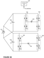
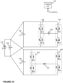
- FIGs 3A-3C schematically illustrate some non-limiting examples of an implementation of the device for multichannel transcranial magnetic stimulation in which there is either a dedicated energy storage for each coils ( Figures 3A and 3B ) or a combination of a dedicated energy storage and a common energy storage ( Figure 3C ).
- FIG 3A schematically illustrates a solution wherein the device is implemented with two separate circuits in such a manner that a control unit 170 is configured to control the input channels 150, 160 in each circuit.
- a control unit 170 is configured to control the input channels 150, 160 in each circuit.
- an own power source 110 marked P1, P2
- an own energy source 120 depicted as capacitors C1 and C2 in Figure 3A
- an own input channel 150, 160 The control unit 170 is coupled to the input channels 150, 160 and specifically to switching devices therein so that it may control the conductive state of the switching devices according to the modulation scheme.
- FIG 3B schematically illustrates another solution wherein the device implemented with a common power source 110, but for each coil 130, 140 a dedicated energy storage 120, such as a capacitor C1, C2, is arranged together with input channel 150, 160.
- a dedicated energy storage 120 such as a capacitor C1, C2
- the power source 110 may be disconnected from the energy storages 120, and connected to one of them at a time with applicable coupling means, such as controllable switches, so that the energy levels of the energy storages C1 and C2 may be adjusted independently of each other.
- FIG 3C it is schematically illustrated a still further example of an implementation of the device for a multichannel transcranial magnetic stimulation.
- the example in Figure 3C comprises an energy storage array consisting of storages 120, wherein one energy storage C is common to both coils 130, 140 and in addition to that there are dedicated energy storages C1 and C2 for each coils 130, 140 that may be located e.g. physically close to the input channels 150, 160, respectively.
- the energy storages 120 are depicted as capacitors in Figure 3C as also in Figures 3A and 3B .
- Each of energy storages 120 may consist of a further storage arrays in any of examples illustrated.
- the energy storages are implemented with capacitors e.g. in the example as illustrated in Figure 3C it is possible to obtain reduced stray inductance compared to the implementation of Figure 2 by selecting the capacitances of the capacitors C1 and C2 smaller than the capacitance of the common capacitor C.
- the difference is especially emphasized when the number of channels is larger than two (as the total system capacitance must be large enough for all channels, and as there will be geometrical constraints in placing the different channels around a single capacitor).
- the wiring between C, C1, and C2 may or may not contain additional components, e.g., inductive parts that affect the circuit behavior.
- the other components depicted in Figure 2 correspond to the ones depicted in Figure 2 .
- Figures 2 and 3A-3C only show relevant elements needed for achieving at least some of the advantages of the present invention. They do not necessarily disclose all elements of a multichannel transcranial magnetic stimulation device.
- the implementations of the circuits in Figures 2 and 3A-3C are non-limiting examples for describing at least some aspects of the present invention.
- the circuits may comprise means for discharging the energy storages. These means may comprise, e.g., resistors or IGBTs.
- the pulse modulation is considered first for the simplest case of ideal half-sine stimulation with a triangular current (assuming a large capacitance for the sake of simplicity of discussion and graphics).
- the effective stimulus location and intensity may be controlled by modulating the coil-current waveforms, and thus also the induced E-field waveforms, during the stimulus pulse.
- This pulse modulation of the induced E-field is achieved by interrupting the increase (or decrease) of the coil current for desired periods of time. The interruption may be achieved by controlling the conducting state of the switches belonging to the input channel of the coil in question, as discussed above.
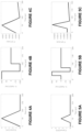
- FIGS 4A-4C schematically illustrate at least some aspects of conventional implementations in which a voltage of the energy storage must be adjusted in order to achieve a desired effect in the target.
- the stimulation of the target is achieved with triangular-pulse provided to a coil in question, wherein the coil current is ramped up and down passively in a monotonic way ( Figure 4A ).
- the E-field is first positive and then negative as shown in Figure 4B .
- the stimulus effect at the neuronal level in the target is shown in Figure 4C , wherein it is assumed that the stimulus effect follows a model introduced by Barker et al. (1991) in which the effect of transcranial magnetic stimulation may be quantified by the parameter:
- F t ⁇ ⁇ ⁇ t E s exp ⁇ t ⁇ s ⁇ ds , wherein
- the capacitor voltage must be adjusted, as the stimulus-intensity control was achieved by scaling the E-field intensity (which is proportional to the rate of change of the current).
- Figures 5A-5C disclose the effect achievable with an example.
- the control of the effective stimulus intensity is at least in part achieved by reversing the rising current when it has reached, in this case, half of the maximum value of the pulse shown in Figure 4A .
- the E-field duration is reduced to half of its original length.
- the maximum E-field intensity ( Figure 5B ), which is determined by the capacitor voltage that controls the rate of change of the current, is unchanged.
- this kind of a current reduces the membrane polarization or the effective stimulus intensity (cf. Figure 5C ) to approximately half of that in Figure 4C .
- this shortening of the pulse may have some non-trivial side effects, when neuronal populations with different time constants are present, or when the pulse duration is long compared to the membrane or cellular time constant.
- the longer pulse of Figure 4A achieved with conventional solutions may lead to saturation that may not happen with the waveform of Figure 5A .
- this limitation may be overcome by making the stimulus waveforms to have (approximately) the same duration by using an in-pulse modulation consisting of multiple steps, as will be discussed next.
- effective stimulus intensity is changed by controlling the current flow suitably i.e. the input channel with the control signal, such as in a step-like manner.
- the effective stimulus intensity may be altered in a wide range of values in a continuous manner.
- the capacitor voltage so that the strongest pulses require some modulation, the stimulus intensity may be also increased by reducing the flat-current portions. This kind of approach enables sharing the energy storage between at least two coils.
- Figures 6A-6C wherein the Figure 6A discloses a step-like increase and decrease of the current input to the coil under use.
- the step-like waveform of the current refers to a form which contains several steps interrupted by near-constant segments.
- the input of the current in the step-like manner is achieved by modulating the current output from the energy storage 120.
- the modulation may be achieved by controlling the switches in the input channels 150, 160 with an applicable control signal, or signals, generated by the control unit 170.
- the step-wise increase and decrease of the input current to the coil 130, 140 causes the E-field to oscillate between the zero level and the maximum level (when the current is increasing) and the minimum level (when the current is decreasing) as shown in Figure 6B .
- the E-field generates the effective stimulus intensity (F) according to the Figure 6C .
- the accuracy of the stimulus intensity may be controlled by selecting necessary number of steps to the current waveform generated through modulation.
- the present invention gives the possibility for multiple channels to share a common energy storage, such as a charge-storage capacitor, which may reduce the size and cost of the device.
- the invention allows using the same voltage level for multiple channels, which by in-pulse modulation may be converted to the desired individual effective intensity in each channel.
- the invention provides means to rapidly change the stimulation target by feeding different channels with their own pulse modulations.
- the modulation pattern may also be time-varying, i.e., the in-pulse modulation may be denser in some parts of the pulse and less frequent in others.
- the example waveforms here started by having a zero current for a few microseconds (as compared to the original waveform), the waveform may as well start with a rising slope.
- the presented in-pulse modulation may be applied to any desired pulse waveform, including mono- and biphasic waveforms. A decrease or increase in the capacitor voltage level during a stimulation session, a finite capacitance, or other non-idealities may be compensated for by adjusting the in-pulse modulation accordingly.
- the effective stimulus waveform By further controlling the effective stimulus waveform as a function of time with a more advanced modulation, one can design pulses that allow optimally measuring the membrane or cellular time constants, e.g., by using simultaneous electroencephalography (EEG) or electromyography (EMG) recordings.
- EEG electroencephalography
- EMG electromyography
- the stimulus waveform may also be modulated in a way that minimizes the stimulus artefacts in combined recordings.
- the waveforms and pulse modulation schemes may be different in different channels.
- the model and its parameters used above when describing the aspects of the present invention may be derived from electromagnetic and physiological theory, from results of measurements, or from their combination; the model may, e.g., be based solely on experimental observation of the stimulation outcome or be based on simulations.
- the model and its parameters may be different from the ones used above.
- the present invention allows one to totally avoid the charging artefact that may occur in physiological (e.g., EEG or EMG) or other type of measurements (e.g., sound or video recording) that are performed together with TMS.
- physiological e.g., EEG or EMG
- other type of measurements e.g., sound or video recording
- the artefact may otherwise disturb the interpretation of the measured signals, when some voltage adjustments would be needed within a pulse train.
- the input channel 150, 160 comprises such switching elements, or components, which are applicable in the context of mTMS.
- IGBT devices may be used, but any other components suitable for switching or adjusting strong currents may be used, such as MOSFETs.
- the control of the coil currents may be combined with knowledge of the physical movement of the coil(s) or the movements of the head or other target tissue so as to achieve the desired E-field spatial pattern in the target area.
- the modulation patterns or sequences of patterns to achieve a desired effective stimulation may e.g. be predetermined and loaded from a storage media accessible for the control unit 170 when needed or the modulation pattern can be computed when needed. The computation may involve optimization of the waveform or it may be achieved without optimization.
- the modulation pattern may also be at least in part dependent on the energy level of the energy storage 120 that may be common to the plurality of coils 130, 140.
- the effective E-field and the coil currents may be controlled by a pulse-width-modulation (PWM) control of the input channels, i.e. the switching devices, such as IGBTs, therein, generated by the control unit 170 in which the flat/rising/descending parts of the current waveform may be shorter than the duration of the pulse.
- PWM pulse-width-modulation
- the effective E-field and coil currents may also be designed to be non-PWM type.
- the stimulus effect and/or location may be controlled by varying, e.g., the total duration of the stimulus waveforms that may or may not be of a triangular/sinusoidal shape.
- the driving electronics of the coils may consist of a single circuit of, e.g., 2 or 4 main IGBTs and 1 or 2 charge-storage capacitors, or it may be built in a modular fashion so that a collection of capacitor are connected/disconnected from the circuit with their own IGBTs when needed.
- This kind of approach allows controlling the pulse waveform in a more detailed manner by varying the number of capacitors and the set of capacitors that are connected to the coil as a function of time or on the basis of the desired effective stimulation outcome.
- the controlling of the chosen energy storages, such as capacitors may be synchronous or asynchronous.
- Figure 7 it is schematically illustrated an example of control signals generated by the control unit 170 in order to generate the modulation pattern as shown in Figure 6 with the circuit implementation as illustrated in Figure 2 .
- Figure 7 illustrates the control signals to be input to the switches S11, S12, S13, and S14 to create the modulation pattern shown in Figure 6 used for controlling an input of the current to the coil 130 in the circuit implementation of Figure 2 .
- the control unit 170 may be configured to generate control signals to other switches in any circuit implementation according to the present invention, such as switches S21, S22, S23 and S24 in the implementation of Figure 2 .
- FIG. 8 schematically illustrates a control unit 170 according to an example of the invention.
- the control unit 170 may be configured, at least in part, to implement at least some functions of the present invention as described. This may be achieved by arranging a processor 810 forming a processing unit in this example to execute at least some portion of computer program code 821A-821 N stored in a memory 820 causing the processor 810, and, thus, the control unit 170 to implement one or more functions as described.
- the processor 810 may be arranged to access the memory 820 and retrieve and store any information therefrom and thereto.
- the processor 810 may be configured to control communication through a communication interface 830 with any external unit, such as with at least one input channel and possibly with any other entity, such as with a device suitable for providing information on energy level of the energy storage common to a plurality of coils.
- the control unit 170 may be communicatively coupled to at least some of the mentioned entities either directly or indirectly.
- the processor 810 may also be configured to control overall operability of mTMS device according to instructions stored in the memory 820 in a form of computer program code and parameters thereto.
- the processor herein refers to any unit suitable for processing information and control the operation of the control unit 170 in achieving a desired operation as described.
- the mentioned operations may e.g.
- control unit 170 as schematically illustrated in Figure 8 is advantageously configured to generate control signals for controlling the modulation of the input current to the coil 130, 140.
- the control signals may refer to signals by means of which it is possible to control conducting states of the switches belonging to the input channel(s) of the device.
- a method not being a part of the invention is schematically illustrated in Figure 9 .
- the method enables at least in part controlling an input of a plurality of coils of a transcranial magnetic stimulation device as described.
- the method may comprise the following steps: determining at least one stimulus intensity 910 intended to be generated in the target by generating magnetic field by at least one coil of the at least two coils; determining an energy level 920 stored in the at least one energy storage; determining a modulation pattern 930 for each coil for generating the magnetic field by the at least one coil of the at least two coils, the generated magnetic field by the at least one coil causing the intended stimulus intensity in the target; generating at least one control signal 940 for controlling the input channel of the at least one coil of the at least two coils according to the determined modulation pattern in order to control an input of each coil from the at least one energy storage.
- the order of these steps may differ from that shown in Figure 9 .
- the present invention enables performing paired-pulse stimulation (or short bursts of stimuli) sequences where the second pulse is equally strong or stronger than the first pulse (or the desired ones of the latter pulses are). Any of the subsequent pulses may also be made weaker than the first pulse. Further, these may be performed without any intermediate charging or discharging, and thus without charging-associated artefact in, for example, EEG signal. Also, as mentioned, in the multichannel TMS it is possible to adjust individual-channel stimulus amplitudes programmatically without need to charge and/or discharge the capacitors. This makes it easier to perform, for example, coil-movement correction for multichannel TMS.
- the present invention allows avoidance of the charging artefact that may occur in physiological (e.g., electroencephalography (EEG) or electromyography (EMG)) or other type of measurements (e.g. sound or video recording) that are performed together with TMS.
- EEG electroencephalography
- EMG electromyography
- other type of measurements e.g. sound or video recording
- the artefact may otherwise disturb the interpretation of the measured signals, when some voltage adjustments would be needed within a pulse train.
- At least one energy storage 120 may be arranged for each coil 130, 140 in a plurality of ways as already mentioned. There may be either at least one common energy storage 120 for a plurality of coils 130, 140. Alternatively, there may be arranged at least one dedicated energy storage 120 for each coil 130, 140. In addition, it is possible to arrange at least one energy storage so that there is at least one common energy storage 120 for the coils 130, 140 and additionally at least one dedicated energy storage 120 for at least some of the coils 130, 140. Still further, one possible arrangement may be that at least one common energy storage 120 is provided for a plurality of coils 130, 140 and at least one dedicated energy storage 120 is provided for at least one coil 130, 140 in the device.
- target shall be understood to cover any object, or some portion of an object, into which stimulation is intended to be generated.
- Some non-limiting examples of the target may e.g. be a brain or only some portion of the brain, a skull or even a specific point in the brain.
Landscapes
- Health & Medical Sciences (AREA)
- Engineering & Computer Science (AREA)
- Biomedical Technology (AREA)
- Nuclear Medicine, Radiotherapy & Molecular Imaging (AREA)
- Radiology & Medical Imaging (AREA)
- Life Sciences & Earth Sciences (AREA)
- Animal Behavior & Ethology (AREA)
- General Health & Medical Sciences (AREA)
- Public Health (AREA)
- Veterinary Medicine (AREA)
- Neurology (AREA)
- Magnetic Treatment Devices (AREA)
Claims (9)
- Vorrichtung zur transkraniellen Magnetstimulation, umfassend:- mindestens zwei Spulen (130, 140),- einen Eingangskanal (150, 160) für jede Spule (130, 140),- eine Steuereinheit (170),- mindestens einen Energiespeicher (120) zum Speichern von Energie für die mindestens zwei Spulen (130, 140),wobei die Steuereinheit (170) konfiguriert ist zum:Bestimmen mindestens einer Stimulusintensität, die in dem Ziel durch Erzeugen eines Magnetfelds durch mindestens eine Spule (130, 140) der mindestens zwei Spulen (130, 140) erzeugt werden soll,Bestimmen eines Energieniveaus, das in dem mindestens einen Energiespeicher (120) gespeichert ist,Bestimmen eines Modulationsmusters individuell für jede Spule (130, 140), wobei das Modulationsmuster mindestens teilweise vom Energieniveau des mindestens einen Energiespeichers (120) abhängt, zum Erzeugen des Magnetfelds durch die mindestens eine Spule (130, 140) der mindestens zwei Spulen (130, 140), wobei das erzeugte Magnetfeld durch die mindestens eine Spule (130, 140) die beabsichtigte Stimulusintensität im Ziel verursacht,Erzeugen mindestens eines Steuersignals zum Steuern des Eingangskanals der mindestens einen Spule (130, 140) der mindestens zwei Spulen (130, 140) gemäß dem bestimmten Modulationsmuster, um einen Stromeingang jeder Spule (130, 140) vom mindestens einen Energiespeicher (120) zu steuern,dadurch gekennzeichnet, dass die Steuereinheit (170) ferner angepasst ist zum:
Steuern des Stromeingangs jeder Spule (130, 140) in einer stufenartigen Weise, wobei eine stufenartige Wellenform des Stromeingangs mehrere ansteigende Schritte und abfallende Schritte umfasst, die durch nahezu konstante Segmente unterbrochen sind. - Vorrichtung zur transkraniellen Magnetstimulation nach Anspruch 1, wobei der mindestens eine Energiespeicher (120) auf eine der folgenden Weisen angeordnet ist: mindestens ein gemeinsamer Energiespeicher (120) für eine Vielzahl der Spulen (130, 140), mindestens ein dedizierter Energiespeicher (120) für jede Spule (130, 140), mindestens ein gemeinsamer Energiespeicher (120) für eine Vielzahl der Spulen (130, 140) und mindestens ein dedizierter Energiespeicher (120) für jede Spule (130, 140), mindestens ein gemeinsamer Energiespeicher (120) für eine Vielzahl von Spulen (130, 140) und mindestens ein dedizierter Energiespeicher (120) für mindestens eine Spule (130, 140).
- Vorrichtung zur transkraniellen Magnetstimulation nach einem der vorhergehenden Ansprüche, wobei der mindestens eine Energiespeicher (120) mindestens einen Kondensator umfasst.
- Vorrichtung zur transkraniellen Magnetstimulation nach einem der vorhergehenden Ansprüche, wobei die Steuereinheit (170) ferner konfiguriert ist, um das in dem mindestens einen Energiespeicher (120) gespeicherte Energieniveau durch Messen eines Spannungsniveaus des mindestens einen Energiespeichers (120) zu bestimmen.
- Vorrichtung zur transkraniellen Magnetstimulation nach einem der vorhergehenden Ansprüche, wobei die Steuereinheit (170) konfiguriert ist, um als Reaktion auf eine Erkennung, dass das in dem mindestens einen Energiespeicher (120) gespeicherte Energieniveau unter einem Energieniveau liegt, das zum Erzeugen eines Magnetfelds mit der mindestens einen Spule (130, 140) benötigt wird, das die beabsichtigte Stimulusintensität im Ziel mit dem bestimmten Modulationsmuster verursacht, ein Aufladen des mindestens einen Energiespeichers (120) einzuleiten.
- Vorrichtung zur transkraniellen Magnetstimulation nach einem der vorhergehenden Ansprüche, wobei die Steuereinheit (170) konfiguriert ist, um das Modulationsmuster zum Erzeugen einer Vielzahl von aufeinanderfolgenden Magnetfeldern mit der mindestens einen Spule (130, 140) zu bestimmen.
- Vorrichtung zur transkraniellen Magnetstimulation nach einem der vorhergehenden Ansprüche, wobei das erzeugte mindestens eine Steuersignal konfiguriert ist, um einen leitenden Zustand von mindestens einer Schaltvorrichtung in mindestens einem Eingangskanal (150, 160) zu steuern.
- Vorrichtung zur transkraniellen Magnetstimulation nach Anspruch 7, wobei die Schaltvorrichtung mindestens eine der Folgenden ist: Bipolartransistor mit isolierter Gate-Elektrode (IGBT); Metall-Oxid-Halbleiter-Feldeffekttransistor (MOSFET).
- Vorrichtung zur transkraniellen Magnetstimulation nach einem der vorhergehenden Ansprüche, wobei die Steuereinheit (170) konfiguriert ist, um den Stromeingang jeder Spule (130, 140) mit einem auf Pulsbreitenmodulation basierenden Steuersignal zu steuern.
Applications Claiming Priority (2)
| Application Number | Priority Date | Filing Date | Title |
|---|---|---|---|
| FI20175309A FI129532B (en) | 2017-04-03 | 2017-04-03 | Control of transcranial magnetic stimulation |
| PCT/FI2018/050238 WO2018185369A1 (en) | 2017-04-03 | 2018-04-03 | Control of transcranial magnetic stimulation |
Publications (3)
| Publication Number | Publication Date |
|---|---|
| EP3606609A1 EP3606609A1 (de) | 2020-02-12 |
| EP3606609C0 EP3606609C0 (de) | 2024-02-14 |
| EP3606609B1 true EP3606609B1 (de) | 2024-02-14 |
Family
ID=62002149
Family Applications (1)
| Application Number | Title | Priority Date | Filing Date |
|---|---|---|---|
| EP18718181.3A Active EP3606609B1 (de) | 2017-04-03 | 2018-04-03 | Steuerung der transkraniellen magnetischen stimulation |
Country Status (5)
| Country | Link |
|---|---|
| US (1) | US11167147B2 (de) |
| EP (1) | EP3606609B1 (de) |
| CN (1) | CN110650776B (de) |
| FI (1) | FI129532B (de) |
| WO (1) | WO2018185369A1 (de) |
Families Citing this family (26)
| Publication number | Priority date | Publication date | Assignee | Title |
|---|---|---|---|---|
| US20180001107A1 (en) | 2016-07-01 | 2018-01-04 | Btl Holdings Limited | Aesthetic method of biological structure treatment by magnetic field |
| US10695575B1 (en) | 2016-05-10 | 2020-06-30 | Btl Medical Technologies S.R.O. | Aesthetic method of biological structure treatment by magnetic field |
| US11247039B2 (en) | 2016-05-03 | 2022-02-15 | Btl Healthcare Technologies A.S. | Device including RF source of energy and vacuum system |
| US11464993B2 (en) | 2016-05-03 | 2022-10-11 | Btl Healthcare Technologies A.S. | Device including RF source of energy and vacuum system |
| US11534619B2 (en) | 2016-05-10 | 2022-12-27 | Btl Medical Solutions A.S. | Aesthetic method of biological structure treatment by magnetic field |
| US10583287B2 (en) | 2016-05-23 | 2020-03-10 | Btl Medical Technologies S.R.O. | Systems and methods for tissue treatment |
| US10556122B1 (en) | 2016-07-01 | 2020-02-11 | Btl Medical Technologies S.R.O. | Aesthetic method of biological structure treatment by magnetic field |
| US11141219B1 (en) | 2016-08-16 | 2021-10-12 | BTL Healthcare Technologies, a.s. | Self-operating belt |
| WO2020065651A1 (en) * | 2018-09-27 | 2020-04-02 | Peled Yona | Method and apparatus for multi-channel simultaneously high power magnetic coil driver |
| EP3866918A4 (de) * | 2018-12-11 | 2022-07-20 | The Regents of the University of California | System für kilohertz transkranielle magnetperturbation (ktmp) |
| US12156689B2 (en) | 2019-04-11 | 2024-12-03 | Btl Medical Solutions A.S. | Methods and devices for aesthetic treatment of biological structures by radiofrequency and magnetic energy |
| PL4417249T3 (pl) | 2019-04-11 | 2026-04-20 | Btl Medical Solutions A.S. | Urządzenia do zabiegów na strukturach biologicznych za pomocą częstotliwości radiowej |
| US12558146B2 (en) | 2019-04-11 | 2026-02-24 | Btl Medical Solutions A.S. | Methods and devices for aesthetic treatment of biological structures by radiofrequency and magnetic energy |
| CN110404172A (zh) * | 2019-07-04 | 2019-11-05 | 广州市爱因电子有限公司 | 一种多功能涌磁治疗仪 |
| CN110448803A (zh) * | 2019-08-19 | 2019-11-15 | 广州市爱因电子有限公司 | 一种人体细胞充能椅 |
| US11878167B2 (en) | 2020-05-04 | 2024-01-23 | Btl Healthcare Technologies A.S. | Device and method for unattended treatment of a patient |
| US12611545B2 (en) | 2020-05-04 | 2026-04-28 | Btl Healthcare Technologies A.S. | Device and method for unattended treatment of a patient |
| ES2993637T3 (en) | 2020-05-04 | 2025-01-03 | Btl Healthcare Technologies As | Device for unattended treatment of a patient |
| EP3995176A1 (de) * | 2020-11-09 | 2022-05-11 | Charité - Universitätsmedizin Berlin | System zur stimulation vom biologischen gewebe |
| US12496457B2 (en) * | 2021-10-08 | 2025-12-16 | Neuroqore, Inc. | Method for generating bidirectional biphasic pulse and use of such pulse |
| US12623087B2 (en) * | 2021-10-08 | 2026-05-12 | Neuroqore, Inc. | Method for generating unidirectional monophasic pulse and use of such pulse |
| CA3260012A1 (en) | 2021-10-13 | 2023-04-20 | Btl Medical Solutions A.S. | AESTHETIC TREATMENT DEVICES FOR BIOLOGICAL STRUCTURES USING RADIOFREQUENCY AND MAGNETIC ENERGY |
| US11896816B2 (en) | 2021-11-03 | 2024-02-13 | Btl Healthcare Technologies A.S. | Device and method for unattended treatment of a patient |
| CN116260230A (zh) * | 2021-12-10 | 2023-06-13 | 上海微创惟美医疗科技(集团)有限公司 | 充放电控制电路及其控制方法 |
| US20260097227A1 (en) | 2024-10-08 | 2026-04-09 | Btl Medical Solutions A.S. | Devices and methods for application of a magnetic field to the nervous system |
| CN121081847B (zh) * | 2025-11-11 | 2026-03-13 | 江西朴拙医疗设备有限公司 | 一种多模态经颅磁刺激控制系统及其控制方法 |
Citations (1)
| Publication number | Priority date | Publication date | Assignee | Title |
|---|---|---|---|---|
| US20160184601A1 (en) * | 2013-06-21 | 2016-06-30 | Technische Universität München | Magnetic stimulator for stimulating tissue with a magnetic field |
Family Cites Families (12)
| Publication number | Priority date | Publication date | Assignee | Title |
|---|---|---|---|---|
| US4875484A (en) * | 1986-10-04 | 1989-10-24 | Total Human Medical Laboratory Co., Ltd. | Method for generating a low frequency electric stimulus signal and low frequency electric stimulus signal generating apparatus |
| GB2298370B (en) | 1995-03-02 | 1997-07-16 | Magstim Co Ltd | Magnetic stimulator for neuro-muscular tissue |
| US6551233B2 (en) | 2001-08-08 | 2003-04-22 | R. B. Carr Engineering, Onc. | Magnetic stimulator power and control circuit |
| CN1879906A (zh) | 2005-06-15 | 2006-12-20 | 郑云峰 | 中枢神经系统磁刺激装置及其使用方法 |
| US7976451B2 (en) | 2005-06-16 | 2011-07-12 | The United States Of America As Represented By The Department Of Health And Human Services | Transcranial magnetic stimulation system and methods |
| US8128549B2 (en) * | 2007-02-20 | 2012-03-06 | Neuronetics, Inc. | Capacitor failure detection |
| US8956273B2 (en) | 2007-08-20 | 2015-02-17 | Cervel Neurotech, Inc. | Firing patterns for deep brain transcranial magnetic stimulation |
| CN101234231A (zh) * | 2008-01-24 | 2008-08-06 | 武汉依瑞德医疗设备新技术有限公司 | 多个刺激线圈的经颅磁场刺激器 |
| US9180305B2 (en) * | 2008-12-11 | 2015-11-10 | Yeda Research & Development Co. Ltd. At The Weizmann Institute Of Science | Systems and methods for controlling electric field pulse parameters using transcranial magnetic stimulation |
| WO2010135425A1 (en) * | 2009-05-19 | 2010-11-25 | The Trustees Of Columbia University In The City Of New York | Systems and methods for inducing electric field pulses in a body organ |
| JP6348575B2 (ja) * | 2013-06-03 | 2018-06-27 | ネクスティム オーワイジェイ | オーバーラッピングするコイル巻き線を有するmTMSコイルデバイス |
| CN106075731A (zh) * | 2016-03-02 | 2016-11-09 | 深圳英智科技有限公司 | 基于经颅磁刺激治疗脑卒中后运动障碍的方法 |
-
2017
- 2017-04-03 FI FI20175309A patent/FI129532B/en active IP Right Grant
-
2018
- 2018-04-03 CN CN201880032668.0A patent/CN110650776B/zh active Active
- 2018-04-03 US US16/500,566 patent/US11167147B2/en active Active
- 2018-04-03 WO PCT/FI2018/050238 patent/WO2018185369A1/en not_active Ceased
- 2018-04-03 EP EP18718181.3A patent/EP3606609B1/de active Active
Patent Citations (1)
| Publication number | Priority date | Publication date | Assignee | Title |
|---|---|---|---|---|
| US20160184601A1 (en) * | 2013-06-21 | 2016-06-30 | Technische Universität München | Magnetic stimulator for stimulating tissue with a magnetic field |
Also Published As
| Publication number | Publication date |
|---|---|
| US11167147B2 (en) | 2021-11-09 |
| EP3606609A1 (de) | 2020-02-12 |
| FI129532B (en) | 2022-04-14 |
| WO2018185369A1 (en) | 2018-10-11 |
| CN110650776A (zh) | 2020-01-03 |
| EP3606609C0 (de) | 2024-02-14 |
| CN110650776B (zh) | 2023-12-26 |
| FI20175309L (fi) | 2018-10-04 |
| FI20175309A7 (fi) | 2018-10-04 |
| US20200101308A1 (en) | 2020-04-02 |
Similar Documents
| Publication | Publication Date | Title |
|---|---|---|
| US11167147B2 (en) | Control of transcranial magnetic stimulation | |
| US9999780B2 (en) | Magnetic stimulation having a freely selectable pulse shape | |
| US11666774B2 (en) | Pulse source and method for magnetically inductive nerve stimulation | |
| KR101292289B1 (ko) | 초점 스윕형 경두개 자기 자극 장치 및 경두개 자기 자극 방법 | |
| JP5706334B2 (ja) | 経頭蓋磁気刺激を用いた電界パルスパラメータの制御のためのシステムおよび方法 | |
| Goetz et al. | Circuit topology and control principle for a first magnetic stimulator with fully controllable waveform | |
| JPH07143971A (ja) | 神経細胞を磁気的に刺激する方法 | |
| Li et al. | Modular pulse synthesizer for transcranial magnetic stimulation with fully adjustable pulse shape and sequence | |
| JP2021518782A (ja) | 中枢神経磁気刺激装置およびそれを備えたヘルスケアまたは医療機器 | |
| CN107929938A (zh) | 一种经颅电磁同步刺激系统 | |
| Gattinger et al. | flexTMS—a novel repetitive transcranial magnetic stimulation device with freely programmable stimulus currents | |
| CN101234231A (zh) | 多个刺激线圈的经颅磁场刺激器 | |
| CA3040164A1 (en) | Wireless neural stimulator with injectable | |
| US20220040491A1 (en) | Methods and Systems for Non-Invasive Focalized Deep Brain Stimulation | |
| WO2021222185A1 (en) | Kilohertz transcranial magnetic perturbation with temporal interference | |
| Li et al. | Modular pulse synthesizer for transcranial magnetic stimulation with flexible user-defined pulse shaping and rapidly changing pulses in sequences | |
| Memarian Sorkhabi et al. | A neurostimulator system for real, sham, and multi-target transcranial magnetic stimulation | |
| Sinisalo et al. | Waveform simulation and pulse-width-modulation approximations with multi-locus tms | |
| Lee et al. | Magnetic stimulation of the sciatic nerve using an implantable high-inductance coil with low-intensity current | |
| CN118698026A (zh) | 用于神经调控的脉冲发生装置、设备及系统 | |
| KR20210066110A (ko) | 펄스 제어 방식의 자기장 치료 장치 | |
| WO2024003537A1 (en) | Selective entrainment of neural rhythms by neural stimulation | |
| EP3326688A1 (de) | Elektrische stimulationsvorrichtung zur behandlung des menschlichen körpers | |
| CN115715217A (zh) | 用于调节神经组织中的神经束的方法和装置 | |
| EP3886976B1 (de) | System zur stimulation des rückenmarks mittels anodischer und kathodischer pulse zur anregung oder unterdrückung des dorsalstrangs |
Legal Events
| Date | Code | Title | Description |
|---|---|---|---|
| STAA | Information on the status of an ep patent application or granted ep patent |
Free format text: STATUS: UNKNOWN |
|
| STAA | Information on the status of an ep patent application or granted ep patent |
Free format text: STATUS: THE INTERNATIONAL PUBLICATION HAS BEEN MADE |
|
| PUAI | Public reference made under article 153(3) epc to a published international application that has entered the european phase |
Free format text: ORIGINAL CODE: 0009012 |
|
| STAA | Information on the status of an ep patent application or granted ep patent |
Free format text: STATUS: REQUEST FOR EXAMINATION WAS MADE |
|
| 17P | Request for examination filed |
Effective date: 20191101 |
|
| AK | Designated contracting states |
Kind code of ref document: A1 Designated state(s): AL AT BE BG CH CY CZ DE DK EE ES FI FR GB GR HR HU IE IS IT LI LT LU LV MC MK MT NL NO PL PT RO RS SE SI SK SM TR |
|
| AX | Request for extension of the european patent |
Extension state: BA ME |
|
| DAV | Request for validation of the european patent (deleted) | ||
| DAX | Request for extension of the european patent (deleted) | ||
| STAA | Information on the status of an ep patent application or granted ep patent |
Free format text: STATUS: EXAMINATION IS IN PROGRESS |
|
| 17Q | First examination report despatched |
Effective date: 20201120 |
|
| GRAP | Despatch of communication of intention to grant a patent |
Free format text: ORIGINAL CODE: EPIDOSNIGR1 |
|
| STAA | Information on the status of an ep patent application or granted ep patent |
Free format text: STATUS: GRANT OF PATENT IS INTENDED |
|
| INTG | Intention to grant announced |
Effective date: 20230227 |
|
| GRAJ | Information related to disapproval of communication of intention to grant by the applicant or resumption of examination proceedings by the epo deleted |
Free format text: ORIGINAL CODE: EPIDOSDIGR1 |
|
| STAA | Information on the status of an ep patent application or granted ep patent |
Free format text: STATUS: EXAMINATION IS IN PROGRESS |
|
| INTC | Intention to grant announced (deleted) | ||
| RAP3 | Party data changed (applicant data changed or rights of an application transferred) |
Owner name: AALTO UNIVERSITY FOUNDATION SR |
|
| GRAP | Despatch of communication of intention to grant a patent |
Free format text: ORIGINAL CODE: EPIDOSNIGR1 |
|
| STAA | Information on the status of an ep patent application or granted ep patent |
Free format text: STATUS: GRANT OF PATENT IS INTENDED |
|
| INTG | Intention to grant announced |
Effective date: 20230925 |
|
| GRAS | Grant fee paid |
Free format text: ORIGINAL CODE: EPIDOSNIGR3 |
|
| GRAA | (expected) grant |
Free format text: ORIGINAL CODE: 0009210 |
|
| STAA | Information on the status of an ep patent application or granted ep patent |
Free format text: STATUS: THE PATENT HAS BEEN GRANTED |
|
| AK | Designated contracting states |
Kind code of ref document: B1 Designated state(s): AL AT BE BG CH CY CZ DE DK EE ES FI FR GB GR HR HU IE IS IT LI LT LU LV MC MK MT NL NO PL PT RO RS SE SI SK SM TR |
|
| REG | Reference to a national code |
Ref country code: GB Ref legal event code: FG4D |
|
| REG | Reference to a national code |
Ref country code: CH Ref legal event code: EP |
|
| REG | Reference to a national code |
Ref country code: DE Ref legal event code: R096 Ref document number: 602018065172 Country of ref document: DE |
|
| REG | Reference to a national code |
Ref country code: IE Ref legal event code: FG4D |
|
| U01 | Request for unitary effect filed |
Effective date: 20240312 |
|
| U07 | Unitary effect registered |
Designated state(s): AT BE BG DE DK EE FI FR IT LT LU LV MT NL PT SE SI Effective date: 20240319 |
|
| U20 | Renewal fee for the european patent with unitary effect paid |
Year of fee payment: 7 Effective date: 20240523 |
|
| PG25 | Lapsed in a contracting state [announced via postgrant information from national office to epo] |
Ref country code: IS Free format text: LAPSE BECAUSE OF FAILURE TO SUBMIT A TRANSLATION OF THE DESCRIPTION OR TO PAY THE FEE WITHIN THE PRESCRIBED TIME-LIMIT Effective date: 20240614 |
|
| PG25 | Lapsed in a contracting state [announced via postgrant information from national office to epo] |
Ref country code: GR Free format text: LAPSE BECAUSE OF FAILURE TO SUBMIT A TRANSLATION OF THE DESCRIPTION OR TO PAY THE FEE WITHIN THE PRESCRIBED TIME-LIMIT Effective date: 20240515 |
|
| PG25 | Lapsed in a contracting state [announced via postgrant information from national office to epo] |
Ref country code: RS Free format text: LAPSE BECAUSE OF FAILURE TO SUBMIT A TRANSLATION OF THE DESCRIPTION OR TO PAY THE FEE WITHIN THE PRESCRIBED TIME-LIMIT Effective date: 20240514 Ref country code: HR Free format text: LAPSE BECAUSE OF FAILURE TO SUBMIT A TRANSLATION OF THE DESCRIPTION OR TO PAY THE FEE WITHIN THE PRESCRIBED TIME-LIMIT Effective date: 20240214 |
|
| PG25 | Lapsed in a contracting state [announced via postgrant information from national office to epo] |
Ref country code: ES Free format text: LAPSE BECAUSE OF FAILURE TO SUBMIT A TRANSLATION OF THE DESCRIPTION OR TO PAY THE FEE WITHIN THE PRESCRIBED TIME-LIMIT Effective date: 20240214 |
|
| PG25 | Lapsed in a contracting state [announced via postgrant information from national office to epo] |
Ref country code: RS Free format text: LAPSE BECAUSE OF FAILURE TO SUBMIT A TRANSLATION OF THE DESCRIPTION OR TO PAY THE FEE WITHIN THE PRESCRIBED TIME-LIMIT Effective date: 20240514 Ref country code: NO Free format text: LAPSE BECAUSE OF FAILURE TO SUBMIT A TRANSLATION OF THE DESCRIPTION OR TO PAY THE FEE WITHIN THE PRESCRIBED TIME-LIMIT Effective date: 20240514 Ref country code: IS Free format text: LAPSE BECAUSE OF FAILURE TO SUBMIT A TRANSLATION OF THE DESCRIPTION OR TO PAY THE FEE WITHIN THE PRESCRIBED TIME-LIMIT Effective date: 20240614 Ref country code: HR Free format text: LAPSE BECAUSE OF FAILURE TO SUBMIT A TRANSLATION OF THE DESCRIPTION OR TO PAY THE FEE WITHIN THE PRESCRIBED TIME-LIMIT Effective date: 20240214 Ref country code: GR Free format text: LAPSE BECAUSE OF FAILURE TO SUBMIT A TRANSLATION OF THE DESCRIPTION OR TO PAY THE FEE WITHIN THE PRESCRIBED TIME-LIMIT Effective date: 20240515 Ref country code: ES Free format text: LAPSE BECAUSE OF FAILURE TO SUBMIT A TRANSLATION OF THE DESCRIPTION OR TO PAY THE FEE WITHIN THE PRESCRIBED TIME-LIMIT Effective date: 20240214 |
|
| PG25 | Lapsed in a contracting state [announced via postgrant information from national office to epo] |
Ref country code: PL Free format text: LAPSE BECAUSE OF FAILURE TO SUBMIT A TRANSLATION OF THE DESCRIPTION OR TO PAY THE FEE WITHIN THE PRESCRIBED TIME-LIMIT Effective date: 20240214 |
|
| PG25 | Lapsed in a contracting state [announced via postgrant information from national office to epo] |
Ref country code: PL Free format text: LAPSE BECAUSE OF FAILURE TO SUBMIT A TRANSLATION OF THE DESCRIPTION OR TO PAY THE FEE WITHIN THE PRESCRIBED TIME-LIMIT Effective date: 20240214 |
|
| PG25 | Lapsed in a contracting state [announced via postgrant information from national office to epo] |
Ref country code: SM Free format text: LAPSE BECAUSE OF FAILURE TO SUBMIT A TRANSLATION OF THE DESCRIPTION OR TO PAY THE FEE WITHIN THE PRESCRIBED TIME-LIMIT Effective date: 20240214 |
|
| PG25 | Lapsed in a contracting state [announced via postgrant information from national office to epo] |
Ref country code: CZ Free format text: LAPSE BECAUSE OF FAILURE TO SUBMIT A TRANSLATION OF THE DESCRIPTION OR TO PAY THE FEE WITHIN THE PRESCRIBED TIME-LIMIT Effective date: 20240214 |
|
| PG25 | Lapsed in a contracting state [announced via postgrant information from national office to epo] |
Ref country code: SK Free format text: LAPSE BECAUSE OF FAILURE TO SUBMIT A TRANSLATION OF THE DESCRIPTION OR TO PAY THE FEE WITHIN THE PRESCRIBED TIME-LIMIT Effective date: 20240214 |
|
| PG25 | Lapsed in a contracting state [announced via postgrant information from national office to epo] |
Ref country code: SM Free format text: LAPSE BECAUSE OF FAILURE TO SUBMIT A TRANSLATION OF THE DESCRIPTION OR TO PAY THE FEE WITHIN THE PRESCRIBED TIME-LIMIT Effective date: 20240214 Ref country code: SK Free format text: LAPSE BECAUSE OF FAILURE TO SUBMIT A TRANSLATION OF THE DESCRIPTION OR TO PAY THE FEE WITHIN THE PRESCRIBED TIME-LIMIT Effective date: 20240214 Ref country code: RO Free format text: LAPSE BECAUSE OF FAILURE TO SUBMIT A TRANSLATION OF THE DESCRIPTION OR TO PAY THE FEE WITHIN THE PRESCRIBED TIME-LIMIT Effective date: 20240214 Ref country code: CZ Free format text: LAPSE BECAUSE OF FAILURE TO SUBMIT A TRANSLATION OF THE DESCRIPTION OR TO PAY THE FEE WITHIN THE PRESCRIBED TIME-LIMIT Effective date: 20240214 |
|
| REG | Reference to a national code |
Ref country code: DE Ref legal event code: R097 Ref document number: 602018065172 Country of ref document: DE |
|
| PG25 | Lapsed in a contracting state [announced via postgrant information from national office to epo] |
Ref country code: MC Free format text: LAPSE BECAUSE OF FAILURE TO SUBMIT A TRANSLATION OF THE DESCRIPTION OR TO PAY THE FEE WITHIN THE PRESCRIBED TIME-LIMIT Effective date: 20240214 |
|
| PG25 | Lapsed in a contracting state [announced via postgrant information from national office to epo] |
Ref country code: MC Free format text: LAPSE BECAUSE OF FAILURE TO SUBMIT A TRANSLATION OF THE DESCRIPTION OR TO PAY THE FEE WITHIN THE PRESCRIBED TIME-LIMIT Effective date: 20240214 |
|
| REG | Reference to a national code |
Ref country code: CH Ref legal event code: PL |
|
| PLBE | No opposition filed within time limit |
Free format text: ORIGINAL CODE: 0009261 |
|
| STAA | Information on the status of an ep patent application or granted ep patent |
Free format text: STATUS: NO OPPOSITION FILED WITHIN TIME LIMIT |
|
| 26N | No opposition filed |
Effective date: 20241115 |
|
| GBPC | Gb: european patent ceased through non-payment of renewal fee |
Effective date: 20240514 |
|
| PG25 | Lapsed in a contracting state [announced via postgrant information from national office to epo] |
Ref country code: CH Free format text: LAPSE BECAUSE OF NON-PAYMENT OF DUE FEES Effective date: 20240430 |
|
| PG25 | Lapsed in a contracting state [announced via postgrant information from national office to epo] |
Ref country code: IE Free format text: LAPSE BECAUSE OF NON-PAYMENT OF DUE FEES Effective date: 20240403 |
|
| PG25 | Lapsed in a contracting state [announced via postgrant information from national office to epo] |
Ref country code: GB Free format text: LAPSE BECAUSE OF NON-PAYMENT OF DUE FEES Effective date: 20240514 |
|
| U20 | Renewal fee for the european patent with unitary effect paid |
Year of fee payment: 8 Effective date: 20250415 |
|
| PG25 | Lapsed in a contracting state [announced via postgrant information from national office to epo] |
Ref country code: CY Free format text: LAPSE BECAUSE OF FAILURE TO SUBMIT A TRANSLATION OF THE DESCRIPTION OR TO PAY THE FEE WITHIN THE PRESCRIBED TIME-LIMIT; INVALID AB INITIO Effective date: 20180403 |
|
| PG25 | Lapsed in a contracting state [announced via postgrant information from national office to epo] |
Ref country code: HU Free format text: LAPSE BECAUSE OF FAILURE TO SUBMIT A TRANSLATION OF THE DESCRIPTION OR TO PAY THE FEE WITHIN THE PRESCRIBED TIME-LIMIT; INVALID AB INITIO Effective date: 20180403 |
|
| PG25 | Lapsed in a contracting state [announced via postgrant information from national office to epo] |
Ref country code: TR Free format text: LAPSE BECAUSE OF FAILURE TO SUBMIT A TRANSLATION OF THE DESCRIPTION OR TO PAY THE FEE WITHIN THE PRESCRIBED TIME-LIMIT Effective date: 20240214 |
|
| U1K | Transfer of rights of the unitary patent after the registration of the unitary effect |
Owner name: CORTISYS OY; FI |