EP3606760B1 - Dispositif et procédé de revêtement de surfaces - Google Patents
Dispositif et procédé de revêtement de surfaces Download PDFInfo
- Publication number
- EP3606760B1 EP3606760B1 EP18776793.4A EP18776793A EP3606760B1 EP 3606760 B1 EP3606760 B1 EP 3606760B1 EP 18776793 A EP18776793 A EP 18776793A EP 3606760 B1 EP3606760 B1 EP 3606760B1
- Authority
- EP
- European Patent Office
- Prior art keywords
- plate
- picoliters
- fluid
- nozzle
- nozzles
- Prior art date
- Legal status (The legal status is an assumption and is not a legal conclusion. Google has not performed a legal analysis and makes no representation as to the accuracy of the status listed.)
- Active
Links
Images















Classifications
-
- B—PERFORMING OPERATIONS; TRANSPORTING
- B41—PRINTING; LINING MACHINES; TYPEWRITERS; STAMPS
- B41J—TYPEWRITERS; SELECTIVE PRINTING MECHANISMS, i.e. MECHANISMS PRINTING OTHERWISE THAN FROM A FORME; CORRECTION OF TYPOGRAPHICAL ERRORS
- B41J2/00—Typewriters or selective printing mechanisms characterised by the printing or marking process for which they are designed
- B41J2/005—Typewriters or selective printing mechanisms characterised by the printing or marking process for which they are designed characterised by bringing liquid or particles selectively into contact with a printing material
- B41J2/01—Ink jet
- B41J2/135—Nozzles
- B41J2/14—Structure thereof only for on-demand ink jet heads
- B41J2/14201—Structure of print heads with piezoelectric elements
-
- B—PERFORMING OPERATIONS; TRANSPORTING
- B05—SPRAYING OR ATOMISING IN GENERAL; APPLYING FLUENT MATERIALS TO SURFACES, IN GENERAL
- B05B—SPRAYING APPARATUS; ATOMISING APPARATUS; NOZZLES
- B05B1/00—Nozzles, spray heads or other outlets, with or without auxiliary devices such as valves, heating means
- B05B1/02—Nozzles, spray heads or other outlets, with or without auxiliary devices such as valves, heating means designed to produce a jet, spray, or other discharge of particular shape or nature, e.g. in single drops, or having an outlet of particular shape
- B05B1/08—Nozzles, spray heads or other outlets, with or without auxiliary devices such as valves, heating means designed to produce a jet, spray, or other discharge of particular shape or nature, e.g. in single drops, or having an outlet of particular shape of pulsating nature, e.g. delivering liquid in successive separate quantities
- B05B1/083—Nozzles, spray heads or other outlets, with or without auxiliary devices such as valves, heating means designed to produce a jet, spray, or other discharge of particular shape or nature, e.g. in single drops, or having an outlet of particular shape of pulsating nature, e.g. delivering liquid in successive separate quantities the pulsating mechanism comprising movable parts
- B05B1/086—Nozzles, spray heads or other outlets, with or without auxiliary devices such as valves, heating means designed to produce a jet, spray, or other discharge of particular shape or nature, e.g. in single drops, or having an outlet of particular shape of pulsating nature, e.g. delivering liquid in successive separate quantities the pulsating mechanism comprising movable parts with a resiliently deformable element, e.g. sleeve
-
- B—PERFORMING OPERATIONS; TRANSPORTING
- B05—SPRAYING OR ATOMISING IN GENERAL; APPLYING FLUENT MATERIALS TO SURFACES, IN GENERAL
- B05B—SPRAYING APPARATUS; ATOMISING APPARATUS; NOZZLES
- B05B13/00—Machines or plants for applying liquids or other fluent materials to surfaces of objects or other work by spraying, not covered by groups B05B1/00 - B05B11/00
- B05B13/002—Machines or plants for applying coating liquids or other fluent materials by inkjet
-
- B—PERFORMING OPERATIONS; TRANSPORTING
- B05—SPRAYING OR ATOMISING IN GENERAL; APPLYING FLUENT MATERIALS TO SURFACES, IN GENERAL
- B05B—SPRAYING APPARATUS; ATOMISING APPARATUS; NOZZLES
- B05B17/00—Apparatus for spraying or atomising liquids or other fluent materials, not covered by the preceding groups
- B05B17/04—Apparatus for spraying or atomising liquids or other fluent materials, not covered by the preceding groups operating with special methods
- B05B17/06—Apparatus for spraying or atomising liquids or other fluent materials, not covered by the preceding groups operating with special methods using ultrasonic or other kinds of vibrations
- B05B17/0607—Apparatus for spraying or atomising liquids or other fluent materials, not covered by the preceding groups operating with special methods using ultrasonic or other kinds of vibrations generated by electrical means, e.g. piezoelectric transducers
- B05B17/0638—Apparatus for spraying or atomising liquids or other fluent materials, not covered by the preceding groups operating with special methods using ultrasonic or other kinds of vibrations generated by electrical means, e.g. piezoelectric transducers spray being produced by discharging the liquid or other fluent material through a plate comprising a plurality of orifices
-
- B—PERFORMING OPERATIONS; TRANSPORTING
- B05—SPRAYING OR ATOMISING IN GENERAL; APPLYING FLUENT MATERIALS TO SURFACES, IN GENERAL
- B05C—APPARATUS FOR APPLYING FLUENT MATERIALS TO SURFACES, IN GENERAL
- B05C5/00—Apparatus in which liquid or other fluent material is projected, poured or allowed to flow on to the surface of the work
- B05C5/02—Apparatus in which liquid or other fluent material is projected, poured or allowed to flow on to the surface of the work the liquid or other fluent material being discharged through an outlet orifice by pressure, e.g. from an outlet device in contact or almost in contact, with the work
-
- B—PERFORMING OPERATIONS; TRANSPORTING
- B41—PRINTING; LINING MACHINES; TYPEWRITERS; STAMPS
- B41J—TYPEWRITERS; SELECTIVE PRINTING MECHANISMS, i.e. MECHANISMS PRINTING OTHERWISE THAN FROM A FORME; CORRECTION OF TYPOGRAPHICAL ERRORS
- B41J2/00—Typewriters or selective printing mechanisms characterised by the printing or marking process for which they are designed
- B41J2/005—Typewriters or selective printing mechanisms characterised by the printing or marking process for which they are designed characterised by bringing liquid or particles selectively into contact with a printing material
- B41J2/01—Ink jet
- B41J2/015—Ink jet characterised by the jet generation process
- B41J2/04—Ink jet characterised by the jet generation process generating single droplets or particles on demand
- B41J2/045—Ink jet characterised by the jet generation process generating single droplets or particles on demand by pressure, e.g. electromechanical transducers
-
- B—PERFORMING OPERATIONS; TRANSPORTING
- B41—PRINTING; LINING MACHINES; TYPEWRITERS; STAMPS
- B41J—TYPEWRITERS; SELECTIVE PRINTING MECHANISMS, i.e. MECHANISMS PRINTING OTHERWISE THAN FROM A FORME; CORRECTION OF TYPOGRAPHICAL ERRORS
- B41J2/00—Typewriters or selective printing mechanisms characterised by the printing or marking process for which they are designed
- B41J2/005—Typewriters or selective printing mechanisms characterised by the printing or marking process for which they are designed characterised by bringing liquid or particles selectively into contact with a printing material
- B41J2/01—Ink jet
- B41J2/135—Nozzles
- B41J2/14—Structure thereof only for on-demand ink jet heads
- B41J2/1433—Structure of nozzle plates
-
- H—ELECTRICITY
- H10—SEMICONDUCTOR DEVICES; ELECTRIC SOLID-STATE DEVICES NOT OTHERWISE PROVIDED FOR
- H10N—ELECTRIC SOLID-STATE DEVICES NOT OTHERWISE PROVIDED FOR
- H10N30/00—Piezoelectric or electrostrictive devices
- H10N30/20—Piezoelectric or electrostrictive devices with electrical input and mechanical output, e.g. functioning as actuators or vibrators
- H10N30/204—Piezoelectric or electrostrictive devices with electrical input and mechanical output, e.g. functioning as actuators or vibrators using bending displacement, e.g. unimorph, bimorph or multimorph cantilever or membrane benders
- H10N30/2041—Beam type
-
- A—HUMAN NECESSITIES
- A61—MEDICAL OR VETERINARY SCIENCE; HYGIENE
- A61M—DEVICES FOR INTRODUCING MEDIA INTO, OR ONTO, THE BODY; DEVICES FOR TRANSDUCING BODY MEDIA OR FOR TAKING MEDIA FROM THE BODY; DEVICES FOR PRODUCING OR ENDING SLEEP OR STUPOR
- A61M37/00—Other apparatus for introducing media into the body; Percutany, i.e. introducing medicines into the body by diffusion through the skin
- A61M37/0015—Other apparatus for introducing media into the body; Percutany, i.e. introducing medicines into the body by diffusion through the skin by using microneedles
- A61M2037/0053—Methods for producing microneedles
-
- B—PERFORMING OPERATIONS; TRANSPORTING
- B05—SPRAYING OR ATOMISING IN GENERAL; APPLYING FLUENT MATERIALS TO SURFACES, IN GENERAL
- B05B—SPRAYING APPARATUS; ATOMISING APPARATUS; NOZZLES
- B05B12/00—Arrangements for controlling delivery; Arrangements for controlling the spray area
- B05B12/08—Arrangements for controlling delivery; Arrangements for controlling the spray area responsive to condition of liquid or other fluent material to be discharged, of ambient medium or of target ; responsive to condition of spray devices or of supply means, e.g. pipes, pumps or their drive means
- B05B12/081—Arrangements for controlling delivery; Arrangements for controlling the spray area responsive to condition of liquid or other fluent material to be discharged, of ambient medium or of target ; responsive to condition of spray devices or of supply means, e.g. pipes, pumps or their drive means responsive to the weight of a reservoir or container for liquid or other fluent material; responsive to level or volume of liquid or other fluent material in a reservoir or container
-
- B—PERFORMING OPERATIONS; TRANSPORTING
- B05—SPRAYING OR ATOMISING IN GENERAL; APPLYING FLUENT MATERIALS TO SURFACES, IN GENERAL
- B05B—SPRAYING APPARATUS; ATOMISING APPARATUS; NOZZLES
- B05B15/00—Details of spraying plant or spraying apparatus not otherwise provided for; Accessories
- B05B15/20—Arrangements for agitating the material to be sprayed, e.g. for stirring, mixing or homogenising
-
- B—PERFORMING OPERATIONS; TRANSPORTING
- B05—SPRAYING OR ATOMISING IN GENERAL; APPLYING FLUENT MATERIALS TO SURFACES, IN GENERAL
- B05B—SPRAYING APPARATUS; ATOMISING APPARATUS; NOZZLES
- B05B15/00—Details of spraying plant or spraying apparatus not otherwise provided for; Accessories
- B05B15/50—Arrangements for cleaning; Arrangements for preventing deposits, drying-out or blockage; Arrangements for detecting improper discharge caused by the presence of foreign matter
-
- B—PERFORMING OPERATIONS; TRANSPORTING
- B05—SPRAYING OR ATOMISING IN GENERAL; APPLYING FLUENT MATERIALS TO SURFACES, IN GENERAL
- B05B—SPRAYING APPARATUS; ATOMISING APPARATUS; NOZZLES
- B05B15/00—Details of spraying plant or spraying apparatus not otherwise provided for; Accessories
- B05B15/50—Arrangements for cleaning; Arrangements for preventing deposits, drying-out or blockage; Arrangements for detecting improper discharge caused by the presence of foreign matter
- B05B15/58—Arrangements for cleaning; Arrangements for preventing deposits, drying-out or blockage; Arrangements for detecting improper discharge caused by the presence of foreign matter preventing deposits, drying-out or blockage by recirculating the fluid to be sprayed from upstream of the discharge opening back to the supplying means
-
- B—PERFORMING OPERATIONS; TRANSPORTING
- B05—SPRAYING OR ATOMISING IN GENERAL; APPLYING FLUENT MATERIALS TO SURFACES, IN GENERAL
- B05B—SPRAYING APPARATUS; ATOMISING APPARATUS; NOZZLES
- B05B17/00—Apparatus for spraying or atomising liquids or other fluent materials, not covered by the preceding groups
- B05B17/04—Apparatus for spraying or atomising liquids or other fluent materials, not covered by the preceding groups operating with special methods
- B05B17/06—Apparatus for spraying or atomising liquids or other fluent materials, not covered by the preceding groups operating with special methods using ultrasonic or other kinds of vibrations
- B05B17/0607—Apparatus for spraying or atomising liquids or other fluent materials, not covered by the preceding groups operating with special methods using ultrasonic or other kinds of vibrations generated by electrical means, e.g. piezoelectric transducers
- B05B17/0653—Details
- B05B17/0669—Excitation frequencies
-
- B—PERFORMING OPERATIONS; TRANSPORTING
- B05—SPRAYING OR ATOMISING IN GENERAL; APPLYING FLUENT MATERIALS TO SURFACES, IN GENERAL
- B05B—SPRAYING APPARATUS; ATOMISING APPARATUS; NOZZLES
- B05B17/00—Apparatus for spraying or atomising liquids or other fluent materials, not covered by the preceding groups
- B05B17/04—Apparatus for spraying or atomising liquids or other fluent materials, not covered by the preceding groups operating with special methods
- B05B17/06—Apparatus for spraying or atomising liquids or other fluent materials, not covered by the preceding groups operating with special methods using ultrasonic or other kinds of vibrations
- B05B17/0607—Apparatus for spraying or atomising liquids or other fluent materials, not covered by the preceding groups operating with special methods using ultrasonic or other kinds of vibrations generated by electrical means, e.g. piezoelectric transducers
- B05B17/0653—Details
- B05B17/0676—Feeding means
-
- B—PERFORMING OPERATIONS; TRANSPORTING
- B05—SPRAYING OR ATOMISING IN GENERAL; APPLYING FLUENT MATERIALS TO SURFACES, IN GENERAL
- B05B—SPRAYING APPARATUS; ATOMISING APPARATUS; NOZZLES
- B05B9/00—Spraying apparatus for discharge of liquids or other fluent material, without essentially mixing with gas or vapour
- B05B9/03—Spraying apparatus for discharge of liquids or other fluent material, without essentially mixing with gas or vapour characterised by means for supplying liquid or other fluent material
- B05B9/04—Spraying apparatus for discharge of liquids or other fluent material, without essentially mixing with gas or vapour characterised by means for supplying liquid or other fluent material with pressurised or compressible container; with pump
- B05B9/0403—Spraying apparatus for discharge of liquids or other fluent material, without essentially mixing with gas or vapour characterised by means for supplying liquid or other fluent material with pressurised or compressible container; with pump with pumps for liquids or other fluent material
- B05B9/042—Spraying apparatus for discharge of liquids or other fluent material, without essentially mixing with gas or vapour characterised by means for supplying liquid or other fluent material with pressurised or compressible container; with pump with pumps for liquids or other fluent material with peristaltic pumps
-
- B—PERFORMING OPERATIONS; TRANSPORTING
- B41—PRINTING; LINING MACHINES; TYPEWRITERS; STAMPS
- B41J—TYPEWRITERS; SELECTIVE PRINTING MECHANISMS, i.e. MECHANISMS PRINTING OTHERWISE THAN FROM A FORME; CORRECTION OF TYPOGRAPHICAL ERRORS
- B41J2/00—Typewriters or selective printing mechanisms characterised by the printing or marking process for which they are designed
- B41J2/005—Typewriters or selective printing mechanisms characterised by the printing or marking process for which they are designed characterised by bringing liquid or particles selectively into contact with a printing material
- B41J2/01—Ink jet
- B41J2/135—Nozzles
- B41J2/16—Production of nozzles
- B41J2/162—Manufacturing of the nozzle plates
-
- H—ELECTRICITY
- H10—SEMICONDUCTOR DEVICES; ELECTRIC SOLID-STATE DEVICES NOT OTHERWISE PROVIDED FOR
- H10N—ELECTRIC SOLID-STATE DEVICES NOT OTHERWISE PROVIDED FOR
- H10N30/00—Piezoelectric or electrostrictive devices
- H10N30/80—Constructional details
- H10N30/88—Mounts; Supports; Enclosures; Casings
Definitions
- the present invention relates to devices and methods for coating of microprojections on microprojection arrays as specified in the claims. Described herein are also print head devices and their manufacture and methods of using the print head devices for manufacturing articles such as microprojection arrays as well as to coating the surfaces of microprojection arrays. The present invention also relates to high throughput printing devices that utilize the print heads described herein.
- microprojection arrays or microneedle arrays have been utilized to deliver various materials through the skin.
- WO 2005/072630 describes devices for delivering bioactive materials and other stimuli to living cells.
- the devices comprise a plurality of projections which can penetrate the skin so as to deliver a bioactive material or stimulus to a predetermined site.
- the projections can be solid and the delivery end of the projection is designed such that it can be inserted into targeted cells or specific sites on the skin.
- Other devices utilizing microprojections and/or microneedles either solid or biodegradable are described in
- Inkjet printing has been used to deposit pharmaceutical compositions on a variety of devices and media.
- Wu et al., (1996) J. Control. Release 40: 77-87 described the use of inkjets to creating devices containing model drugs
- Radulescu et al. (2003) Proc. Winter Symposium and 11th International Symposium on Recent Advance ins Drug Delivery Systems described the preparation of small diameter poly(lactic-co-glycolic acid) nanoparticles containing paclitaxel using a piezoelectric inkjet printer; Melendez et al. (2008) J. Pharm. Sci. 97: 2619-2636 utilized inkjet printers to produce solid dosage forms of prednisolone; Desai et al. (2010) Mater. Sci. Eng.
- Spotting of DNA microarrays is achieved traditionally using a computer-controlled xyz motion stage with a head carrying a pen device to pick up small drops of solution from the multiwell plates for transfer and spotting them onto a surface.
- These spotting pens are sophisticated designs adapted from the quill type of ink pen.
- the pen printing is reliable and repeatable when using a flat solid surface substrate. Problems can arise with the contact technology when using uneven and membrane types of substrates. The uneven substrates can result in missed spots when the surface regions are lower than the level of a pen or pens within a bank of printing pens. Spotting onto membranes can result in unacceptable surface indentations and uneven spotting if the membrane absorbs the spotting solution too quickly.
- Positive pressure displacement is another spotting method that utilizes a syringe system or valve jet for deposition of the fluids.
- a syringe system or valve jet for deposition of the fluids.
- valve-jet technology an orifice or nozzle is attached to a solenoid valve that opens and shuts rapidly to produce streams of intermittent droplets from a pressurized flow.
- a syringe system picks up the fluid from sample wells and then dispenses the fluid onto the substrate using positive displacement.
- These systems are highly reliable, as the fluidic property influence on dispensing is less than the effect on piezoelectric microdispensing.
- these positive pressure displacement microdispensing systems can have lower repeatability rates when dispensing at their lower volume capabilities.
- the low-end deposition volumes for these systems are in the nanoliter range.
- the fluid is maintained at ambient pressure and a piezoelectric transducer is used to create a drop only when needed.
- the transducer creates a volumetric change in the fluid resulting in pressure waves.
- the pressure waves travel to the orifice, are converted to fluid velocity which results in a drop being ejected from the orifice.
- the piezo transducer establishes an acoustic pulse which alters the fluid meniscus profile at the orifice.
- the accuracy of ink-jet dispensing is not affected by how the fluid wets a substrate, as is the case of positive displacement or pen transfer systems "touching off' the fluid onto the substrate during the dispensing event.
- the fluid source cannot be contaminated by fluid already on the substrate or by the substrate material. Therefore, it is possible to overprint spots using a different reagent or biofluid without the risk of cross contamination.
- the ability to free-fly the droplets of fluid over a millimeter or more allows fluids to be dispensed into wells or other substrate features.
- the current inkjet systems used to coat medical devices including microprojection arrays utilize an XYZ gantry system for positioning either single nozzles, or arrays of individually addressable nozzles which then deliver the coating over the microprojections.
- the print head is rastered across the target substrate which involves the acceleration and de-acceleration of the axis for each line that is printed.
- the print head must be sabred (i.e. Located at an angle) and have variable timing on the ejection of drops in order to leverage the speed increase available when using multiple nozzles.
- the present invention relates to devices and methods for coating of microprojections on microprojection arrays as characterized in the claims.
- the present invention also relates to print head devices and to methods of using the print head devices for coating the surfaces of microprojection arrays.
- the present invention also relates to high throughput devices that utilize the print heads described herein to produce a large number of coated microprojection arrays.
- the present invention relates to devices and methods for depositing materials onto substrates.
- the devices and methods of the present invention can be used to print or coat or cover or deposit materials, in particular fluid materials onto substrates.
- the devices and methods of the present invention can be used to coat fluids onto substrates such as coating a stent or coating the microprojections of a microprojection array.
- the present invention relates to devices for printing or coating of fluids including pharmaceuticals and biological materials onto microprojection arrays which may provide improved efficiency and precise coating of three dimensional substrates.
- the devices of the present invention provide simultaneous two dimension deposition of pharmacological grade biological material in an aseptic environment. These printing devices provide for the coating of different antigens on different microprojections of a microprojection array.
- the devices of the present invention can also deposit different antigens and different adjuvants or excipients on any microprojection on a microprojection array.
- biological fluids include vaccines and biopharmaceuticals which pose an additional challenge for coating in that the active material may only be available in low concentrations such as 1-10 mg/ml.
- the total fluid delivered may be relatively high (the number of drops) it is important to efficiently deposit the material so that the total time to coat the substrate is not excessive.
- a microprojection array platform has a length and width of less than 20 mm and carries an evenly spaced two-dimensional array of projections.
- the number of projection in each direction is typically less than 100 and therefore the density of projections on the array is between 2000 and 10000 projections per cm 2 .
- the amount of material needed for an effective dose is typically about 500 to 1000 picoliters per projection.
- Currently available printer technology is not made to print pharmaceutical grade material nor can current technology print with the accuracy required to provide the appropriate amount of material on each projection.
- multinozzle printer heads are designed for document and graphic printing where the focus is on variable data addressability, high DPI in one dimension and small drop size (typically less than 30 picoliters). These characteristics do not fit the requirements necessary to produce inkjet coating of microprojection arrays. Moreover, commercial print heads do not provide cooling and mixing functions which permit biological materials to remain stable during the coating process.
- the present invention provides a device for coating a microprojection array with a fluid comprising: a piezoelectric actuator; a membrane plate; a deformation clearance plate; a restrictor pumping chamber provided with air venting facilities surrounding the pumping chamber such that as the pumping chamber is filled with the fluid, the air in each area of the pumping chamber has a separate channel to escape; and a nozzle plate wherein the nozzle plate has a plurality of nozzles and has a nozzle density of between 1500 and 3500 nozzles per cm 2 and wherein the nozzle plate comprises venting holes connected to each air venting facility in the pumping chamber, wherein the venting holes are straight and smaller in diameter than the nozzles.
- the piezoelectric actuator is a piezoelectric stack actuator.
- the piezoelectric actuator is a piezoelectric unimorph actuator.
- the device further comprising a device for mixing the fluid.
- the device further comprises a housing.
- the housing of the device may contain a cooling device.
- the pumping chamber plate further comprises one or more fluid ports by which the fluid is pumped into the pumping chamber.
- the nozzle plate has multiple fluid ports.
- the nozzles are made of etched silicon.
- the nozzles are made of electroformed nickel.
- the nozzles are made of EDM stainless steel.
- the nozzles are made of mechanically punched stainless steel.
- the nozzles are made of laser-drilled stainless steel.
- the nozzles are made in a two dimensional array.
- the nozzle diameter is from about 30 ⁇ m to 200 ⁇ m.
- the number of nozzles in the two dimensional array is between 100 to 5000.
- the spacing between the nozzles is from about 80 to about 800 micrometers.
- each nozzle dispenses about 30 to 3000 picoliters of fluid.
- the nozzles are coated to increase durability.
- the nozzles are coated to increase hydrophobicity.
- the fluid is a biological material.
- the fluid is a vaccine.
- the pumping chamber is moulded.
- the device is pre-primed with a priming solution.
- the membrane plate is made of stainless steel.
- the device is aseptic.
- nozzles are aseptic.
- the device is disposable.
- nozzle plate is disposable.
- the pumping chamber is disposable.
- the biological fluid is kept in a sterile condition.
- the vaccine is kept in a sterile condition.
- the present invention provides a device according to claim 9.
- the present invention provides a method for coating a microprojection array the method including: aligning the device as characterized in the claims over a microprojection array comprising a plurality of microprojections such that each nozzle is aligned over microprojections that are uncoated; and activating the actuator such that the membrane plate pushes fluid through the nozzles and onto the microprojections thereby coating the microprojections.
- the nozzles are from about 50 to about 2000 micrometers from the microprojections.
- the alignment of the device over the microprojection array is accomplished by utilizing a camera.
- the device may further comprise a second restrictor plate.
- the device may further comprise a second restrictor plate.
- top plate typically the top plate, fluid distribution plate, piezoelectric membrane plate, piezoelectric deformation clearance plate, pumping chamber plate and nozzle plate are all contained within a housing.
- the nozzle plate is from about 200 to 500 ⁇ m thick.
- the pumping chamber is less than 1 mm in thickness
- the nozzle geometry of the nozzles in the nozzle plate is continuous and has no singular points.
- the pumping chamber plate has venting holes.
- the nozzle plate has venting holes.
- the nozzle plate venting holes are connected to the pumping chamber air venting facilities.
- venting holes are less than or equal to 50 ⁇ m in diameter.
- the pumping chamber plate has two restrictors.
- the nozzle plate is comprised of two plates including a descender plate.
- Micro Array Projections or Micro Array Patches encompass a large number of disparate devices which are currently in development.
- Other terms for these devices include microneedle arrays, microprojection patches and microneedle patches.
- These patches can be an alternative to the administration of vaccines and other pharmacological substances via dermal or intramuscular injections by providing a method in which the substances are administered through the outer layer of the skin.
- the patches take a variety of forms from metal formed patches to polymer molded patches to patch projections formed from the vaccine or pharmacological solution itself. The manufacture of these patches relies on the ability to deposit a dried down drug solution or vaccine onto the tips of the microprojections with high throughput and high accuracy.
- PAT Process Analytical Technology
- the devices and methods of the present invention relate to an integrated control system that uses novel print head and nozzle plate design and manufacture, novel process control, novel PZT driving waveforms and inventive process steps that ensure process control and quality output is maintained at all times.
- the methods and devices of the present invention include a design for a coating system that will be acceptable for the manufacture of combination medical devices to be labelled as aseptically sterile, and provide a control system that will conform to the standards provided by global regulatory bodies.
- the present invention relates to devices and methods for coating medical devices including microprojection arrays as characterized in the claims. Described herein are novel print head designs that utilize a piezoelectric stack actuator as the driving component to push a membrane plate such that the fluid in the pumping chamber is dispensed though a two-dimensional array of nozzles.
- the dispensed fluid is coated onto microprojections on a microprojection array as the nozzles are aligned with the microprojections on the array.
- the number of nozzle in each of the two-dimensional directions may be less than 100 nozzles and the number of nozzles may be evenly divided by the number of projections in the microneedle array that is being coated or may be the same number as the number of projections to be coated.
- the spacing between the nozzles may be a whole number multiple of the spacing between the microprojections in the microprojection array.
- the device and methods of the present invention may provide that each drop ejection cycle enable all the nozzles to simultaneously dispense a drop or a sequence of drops with a total volume in the range of 30 to 3000 picoliters per nozzle.
- the device and methods of the present invention may provide that each drop ejection cycle enable a single nozzle or subset of nozzles to dispense a drop or a sequence of drops.
- Described herein is also a print head in which the nozzle plate provides a two-dimensional array of nozzle for dispensing material.
- a print head device is shown in Figures 1 and 2 .
- a piezoelectric stack actuator is used.
- the housing (101) is connected to the pumping chamber (106) where the fluid to be dispensed is stored.
- the fluid flows into the pumping chamber through one or more ports (107).
- the piezoelectric stack (102) is activated and impinges on the plate membrane (104) which is held between two restrictor plates (103 and 105).
- the descender plate (108) is attached to the nozzle plate (109) such that when the piezoelectric stack (102) is activated, fluid is pushed by the plate membrane (104) through the descender plate (108) and out through the nozzles in the nozzle plate (109) to be distributed onto the microprojections.
- the print head is assembled by passing the screws through the housing (101), the first restrictor plate (103), the membrane plate (104), the second restrictor plate (105) and into the pumping chamber (106).
- the pre-loaded force of the stack PZT (102) onto the membrane plate (104) is set using a direct current force gauge.
- the pre-loaded force is used to fine tune the performance of the different print head assemblies so that optimal performance may be achieved.
- the components above the membrane plate i.e. the housing (101), stack PZT (102) and first restrictor plate (103)
- the components below and including the membrane plate may be disposable.
- the restrictor plates may serve as an internal fluidic conduit where the biological fluid flows through the restrictor and into the area below the membrane plate.
- Figures 3-6 provide an alternate print head device described herein in which a unimorph piezoelectric unit is used.
- the housing (301) is connected to the pumping chamber (305) where the fluid to be dispensed is stored.
- the fluid flows into the pumping chamber through one or more ports (306).
- the unimorph piezoelectric device (302) is activated and impinges on the plate membrane (303) which is held by a restrictor plate (304).
- the descender plate (307) is attached to the nozzle plate (308) such that when the unimorph piezoelectric (302) is activated, fluid is pushed by the plate membrane (304) through the descender plate (307) and out through the nozzles in the nozzle plate (308) to be distributed onto the microproj ections.
- the housing (501) has ports (501) for conducting fluid into the pumping chamber (506).
- the unimorph PZT (503) impacts the plate membrane (504) which is held in place by a restrictor plate (505). All of these parts are assembled with the housing (506) and the descender plate (507) and nozzle plate (508).
- the embodiments utilizing the unimorph PZT are assembled using a bio-compatible epoxy.
- the unimorph PZT is significantly less expensive than the stack PZT and thus the manufacturing cost may be lowered providing a print head that is fully disposable. Because the unimorph PZT has less variability in its performance, the product performance variation may be tighter. Because unimorph PZT is smaller, the print head footprint may be smaller as well (e.g.
- Figure 9 show a schematic diagram of a piezoelectric stack actuator
- Figure 10A and B show views of one embodiment of the assembled print head device.
- Figure 11 provides an additional embodiment of the print head of the present invention.
- the parts of this embodiment of the print head include the piezoelectric device (1103), the membrane plate (1104), the deformation clearance plate (1101), the restrictor pumping chamber (1102) and the nozzle plate (1108).
- the deformation clearance plate is between the membrane plate and the pumping chamber plate.
- the membrane plate is deformed by the piezoelectric actuator toward the deformation clearance plate and the maximum deformable area in the membrane plate is defined by the deformation clearance plate.
- the deformation clearance plate (1101) is functioning in a manner similar to the restrictor plate (105) of the previous examples.
- FIG. 12 provides a schematic of a top view of one embodiment of the restrictor pumping chamber.
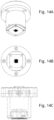
- Figure 13 provides a schematic diagram of the print head assembly shown in Figure 11 within a housing which includes the cartridge cap (1310), the cartridge body (1311) and an adapter plate (1312).
- the adapter plate may be removable which permits the interchange of nozzle arrays.
- Figures 14A-C and 15A and B show various views of the print head assembly inside the housing.
- the various parts of the print head may be assembled in a variety of ways including but not limited to diffusion bonding, epoxy bonding, laser welding or a combination thereof.
- diffusion bonding the parts of the print head assembly are coated with a bonding layer (e.g. gold), aligned and then diffusion bonded. Diffusion bonding may be preferred as it is a more permanent approach less prone to leakage and hole blockage due to adhesive leaking into the holes.
- epoxy boding a thin layer of adhesive (approximately 3 ⁇ m) is applied to each surface and the parts are aligned in a jig and then placed under pressure and heat to bond.
- laser welding the areas that require a water tight bond are laser welded in order to build the final assembly.
- the piezoelectric device (1103) may be adhesive bonded to the membrane plate (1104) to form one sub-assembly.
- the deformation clearance plate (1101), the restrictor pumping chamber (1102) and the nozzle plate (1108) can be diffusion bonded to one another to form a second sub-assembly. These two sub-assemblies can then be adhesive bonded together to form the print head.
- the deformation clearance plate (1101), the restrictor pumping chamber (1102) and the nozzle plate (1108) can be laser welded together and this sub-assembly adhesive bonded to the piezoelectric device (1103) /membrane plate (1104) sub-assembly.
- Another alternative is to adhesive bond all of the parts together.
- the print head functions in the following way.
- the print head has a source of fluid from a reservoir which may be integral or externally located. Initially, the fluid from the reservoir to the nozzle is at a static condition, i.e., no flow. Between the reservoir and the nozzle, there are microfluidic conduits and a pumping chamber. The microfluidic conduits are responsible for replenishing fluid from the reservoir to the pumping chamber. The pumping chamber is responsible for pumping fluid out from the nozzle. At the nozzle exit, there is a meniscus or liquid/air interface defined by the nozzle exit geometry, which is some embodiments forms a round meniscus.
- the meniscus has a concave shape, which generates a capillary pressure and provides the means to maintain the fluid inside the pumping chamber from leaking out from the nozzle.
- the piezoelectric actuator is energized by the electric driving signal.
- the activation of the piezoelectric actuator is complete.
- the activated piezoelectric actuator then pushes the membrane plate to generate a positive pressure wave in the pumping chamber.
- the fluid inside the pumping chamber propagates the pressure wave in all directions, i.e., through the nozzle to the nozzle meniscus and through the fluidic conduits to the reservoir.
- the pressure wave that is propagated to the reservoir is dampened out as the reservoir has a huge free surface (a large liquid/air interface with lots of compliance).
- t1 is less than a few microseconds; t2-t1 is less than a few microseconds; t3-t2 is less than tens of microsecond; t4 is about the same as t3; t5 may be about hundreds of seconds.”
- the alignment of the descender plate and nozzle plate is an important factor in the performance of the print head.
- An alignment tool may be used to align these two plate such that the holes in each the descender plate and nozzle plate are aligned with each other.
- the deformation clearance plate may be used to retain in place a portion of the membrane that is not used in pushing the fluid
- the number of nozzle in each of the two-dimensional directions may be less than 100 nozzles or less than 90 nozzles or less than 80 nozzles or less than 70 nozzles or less than 60 nozzles or less than 50 nozzles or less than 40 nozzles or less than 30 nozzles or less than 20 nozzles or less than 10 nozzles.
- the number of nozzles in a given direction may be between 10 and 100 nozzles or between 10 and 90 nozzles or between 10 and 80 nozzles or between 10 and 70 nozzles or between 10 and 60 nozzles or between 10 and 50 nozzles or between 10 and 40 nozzles or between 10 and 30 nozzles or between 10 and 20 nozzles or be between 20 and 100 nozzles or between 20 and 90 nozzles or between 20 and 80 nozzles or between 20 and 70 nozzles or between 20 and 60 nozzles or between 20 and 50 nozzles or between 20 and 40 nozzles or between 20 and 30 nozzles or be between 30 and 100 nozzles or between 30 and 90 nozzles or between 30 and 80 nozzles or between 30 and 70 nozzles or between 30 and 60 nozzles or between 30 and 50 nozzles or between 30 and 40 nozzles or be between 40 and 100 nozzles or between 40 and 90 nozzles or between 40 and 80 nozzles or between 40 and 70 nozzles or between 40 and 60 nozzles or between 40 and 50 nozzle
- Nozzles can be spaced between about 50 to 500 micrometers, or from about 50 to 450 micrometers or from about 50 to 400 micrometers, or from about 50 to 350 micrometers or from about 50 to 300 micrometers, or from about 50 to 250 micrometers or from about 50 to 200 micrometers, or from about 50 to 150 micrometers or from about 50 to 100 micrometers, or from about 100 to 500 micrometers or from about 100 to 450 micrometers, or from about 100 to 400 micrometers or from about 100 to 350 micrometers or from about 100 to 300 micrometers, or from about 100 to 250 micrometers or from about 100 to 500 micrometers or from about 100 to 450 micrometers, or from about 100 to 400 micrometers or from about 100 to 350 micrometers or from about 100 to 300 micrometers, or from about 100 to 250 micrometers or from about 100 to 200 micrometers or from about 100 to 150 micrometers, or from about 150 to 500 micrometers or from about 150 to 450 micrometers or from about 150 to 400 micrometers
- the density of the nozzles in the nozzle array is from 1,500 to 3,500 nozzles per cm 2 , preferably from about 1,500 to 3,000 nozzles per cm 2 or from 1,500 to 2,500 nozzles per cm 2 , or from about 1,500 to 2,000 nozzles per cm 2 , or from about 2,000 to 3,500 nozzles per cm 2 , or from about 2,000 to 3,000 nozzles per cm 2 or from 2,000 to 2,500 nozzles per cm 2 , or from about 2,500 to 3,500 nozzles per cm 2 , or from about 2,500 to 3,000 nozzles per cm 2 or from about 3,000 to 3,500 nozzles per cm 2 ,
- the number of nozzles would correspond directly to the number of projections on the microprojection array.
- the microprojection array would have 1444 projections in the same spatial orientation as the nozzle array for a one-to one correspondence.
- the spacing of the microprojections on the microprojection array would be the same as the spacing of the nozzles.
- the spacing of the microprojections may be closer than that of the nozzles. For example if the spacing between microprojections on a microprojection array is 120 micrometers, the spacing of the nozzles may be 240 micrometers such that the nozzles would coat every other microprojection.
- the correspondence of the nozzles to the microprojections would be 1 to 2.
- the spacing between microprojections on a microprojection array is 120 micrometers
- the spacing of the nozzles may be 480 micrometers such that the nozzles would coat every fourth microprojection.
- the correspondence of the nozzles to the microprojections would be 1 to 4.
- the design is not limited to uniform square or rectangular arrays but can print abstract geometric shapes, (smiley face, circular etc.) Not having to move the print head over the array speeds up the process and improves targeting accuracy.
- the nozzle array of the print head will not coat all of the microprojections designated for coating in a single pass.
- the nozzle array is two dimensional array that has 38 x 38 nozzles and the microprojection array has 5776 microprojections arranged as a 76 x 76 array the nozzles may need to move relative to the microprojection array.
- the microprojection array can be seen as having four quadrants each of 1444 microprojections. To coat the projections on the entire array the print head carrying the nozzles can be moved relative to the microprojection array three times after the first positioning such that each of the quadrants can be coated.
- the microprojection array can be moved relative to the print head and again the four quadrants can be coated.
- any microprojection array that has a number of microprojections that are a multiple of the number of nozzles can be coated by the print head by moving the print head or microprojection array relative to each other such that the nozzles are aligned over the microprojection quadrant by quadrant.
- the microprojections of the microprojection array are more closely spaced than the nozzles of the print head.
- the microprojection array may have 11552 and the nozzle array has 38 x 38 nozzles which are aligned with every other microprojection.
- the nozzle array may coat every other microprojection in the first or four quadrants and then the microprojection array and the nozzle array can be moved relative to each other such that a second microprojection array quadrant can be coated and so on so that the entire microprojection array is coated having every other microprojection coated.
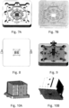
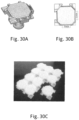
- the nozzles can be arrayed in a nozzle plate as shown in Figures 16A-D .
- the two-dimensional array of nozzles can be made from but is not limited to materials such as etched silicon or electroformed nickel.
- the nozzle plate may be attached to a descender plate ( Figure 16D ) which is attached to a pumping chamber ( Figure 7 ) such that the combination of the nozzle plate/descender plate and the pumping chamber are sealed and permit the influx of a fluid to be dispensed through the nozzles in the nozzle plate.
- the descender plate and nozzle plate may be attached by direct bonding if silicon is used or if stainless steel plates are used then either epoxy bonding or diffusion bonding can be used.
- nozzle plate there may be a single nozzle plate without a descender plate. If there is only one plate below the pumping chamber plate, it is called nozzle plate. If however two plates are used to make the nozzle plate, then the top one is called descender plate and the bottom one is called the nozzle plate.
- the nozzle plate and descender plate are 20x20 mm square. In one embodiment the nozzle plate the thickness of nozzle plate is 0.05 to 0.1 mm and the thickness of descender plate is 0.10 0.25 to 1.0 mm.
- the nozzle plate may be coated to enhance durability and hydrophobicity.
- the nozzle plate may also have fluidic ports which are moulded or machined into the plate permit filling of the pumping chamber and recirculation of the fluid during the coating process. ( Figure 8 ) The recirculation of the fluid during the coating process may provide mixing for the fluid.
- the drop size may be determined by the energy of the drop mass. If the drop is too large it will not remain at the top of the projection but slide down the projection towards the base. If the drop is too large it may also span more than one projection. If the drop is too small the process becomes inefficient. Stability data indicates that smaller quicker drying drops may provide longer shelf life. Drop size may be less than 500pl or less than 400pl or less than 300pl or less than 200pl or less than 100pl.
- Drop size may range from about 10pl to about 500pl or from about 10pl to about 400pl or from about 10pl to about 300pl or from about 10pl to about 200pl or from about 10pl to about 100pl or from about 10pl to about 50pl or from about 50pl to about 500pl or from about 50pl to about 400pl or from about 50pl to about 300pl or from about 50pl to about 200pl or from about 50pl to about 100pl or from about 100pl to about 500pl or from about 100pl to about 400pl or from about 100pl to about 300pl or from about 100pl to about 200pl or from about 200pl to about 500pl or from about 200pl to about 400pl or from about 200pl to about 300pl. Drop size may be about 100pl or 105pl or 110pl or 115pl or 120pl or 125pl or 130pl or 135pl or 140pl or 145pl or 150p
- Each drop ejection cycle enables all the nozzles to simultaneously dispense a drop or a sequence of drops with a total volume in the range of 20 to 3000 picoliters, or 20 to 2500 picoliters, or 20 to 2000 picoliters or 20 to 1500 picoliters or 20 to 1000 picoliters, or 20 to 900 picoliters, or 20 to 800 picoliters, or 20 to 700 picoliters, or 20 to 600 picoliters, or 20 to 500 picoliters, or 20 to 400 picoliters, or 20 to 300 picoliters, or 20 to 200 picoliters, or 20 to 100 picoliters, or 20 to 90 picoliters, or 20 to 80 picoliters or 20 to 70 picoliters, or 20 to 60 picoliters, or 20 to 50 picoliters, or 20 to 40 picoliters or 20 to 30 picoliters, or 30 to 3000 picoliters, or 30 to 2500 picoliters, or 30 to 2000 picoliters or 30 to
- the drop size of each individual drop may be from about 100 to 200 picoliters, or 100 to 190 picoliters, or 100 to 180 picoliters, or 100 to 170 picoliters, or 100 to 160 picoliters, or 100 to 150 picoliters, or 100 to 140 picoliters, or 100 to 130 picoliters, or 100 to 120 picoliters or from 100 to 110 picoliters, or from about 110 to 200 picoliters, or 110 to 190 picoliters, or 110 to 180 picoliters, or 110 to 170 picoliters, or 110 to 160 picoliters, or 110 to 150 picoliters, or 110 to 140 picoliters, or 110 to 130 picoliters, or 110 to 120 picoliters or from about 120 to 200 picoliters, or 120 to 190 picoliters, or 120 to 180 picoliters, or 120 to 170 picoliters, or 120 to 160 picoliters, or 120 to 150 picoliters, or 120 to 140 picoliters, or
- the frequency of dispensing the drops is from about 1Hz to about 1000Hz or from about 1Hz to about 900Hz or from about 1Hz to about 800Hz or from about 1Hz to about 700Hz or from about 1Hz to about 600Hz or from about 1Hz to about 500Hz or from about 1Hz to about 400Hz or from about 1Hz to about 300Hz or from about 1Hz to about 200Hz or from about 1Hz to about 100Hz or from about 1Hz to about 90Hz or from about 1Hz to about 80Hz or from about 1Hz to about 70Hz or from about 1Hz to about 60Hz or from about 1Hz to about 50Hz or from about 1Hz to about 40Hz or from about 1Hz to about 30Hz or from about 1Hz to about 20Hz or from about 1Hz to about 10Hz or from about 10Hz to about 100Hz or from about 10Hz to about 90Hz or from about 10Hz to about 80Hz or from about 10Hz to about 70Hz or from about 10Hz to about 60Hz or from about 10Hz to about 50Hz or from about 10Hz to about 40Hz or from about 10Hz to about 30Hz or from
- a burst mode priming procedure may be run at high frequencies, for example about 1 kHz for 10 bursts. At higher frequency, such a priming mode may be used to re-establish the meniscus position and shape.
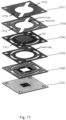
- Figure 17 shows print heads in which the top plate is less than 100 ⁇ m and has one inlet and one outlet which can provide for the recirculation of fluid.
- the print head has a top plate (1711) which has a single inlet (1712) and outlet (1713).
- a fluid distribution plate (1714) which has reservoirs (1715) for the printing fluid.
- the piezoelectric device (1716) below which is the piezoelectric membrane (1717), both of which are within the piezoelectric-membrane plate (1718).
- the distribution plate may be up to 2mm thick and provides two reservoirs to help dampen the acoustic wave transmitted from the pumping chamber through the restrictors. The larger the volume of the reservoirs the better the dampening and frequency response which will maintain drop size and drop velocity.
- the centre ring of the plate should be at least 1mm larger in diameter than the diameter of the piezo. This is used to clamp the PZT-membrane plate to have a simply supported beam structure so that deformation of the PZT can still be achieved.
- the PZT plate provides acoustic energy for drop formation.
- the PZT is actuated by electric signals which pushes the membrane which in turn creates a pressure change in the fluid below the membrane.
- the membrane plate in preferred embodiments of the print heads is about or less than 100 ⁇ m in thickness.
- the PZT deformation clearance plate should be from about 20 to 60 ⁇ m in thickness.
- Figure 18A and 18B discloses a preferred embodiment of the pumping chamber plate of the print heads.
- Figure 18A is a top view of the pumping chamber plate and 18B is a top view of the assembly.
- the fluid comes in from the fluid inlet (1801), then flows into the pumping chamber area through a restrictor 1 (1802). After the pumping chamber is filled with fluid the fluid flows through restrictor 2 (1803) to the fluid outlet (1804).
- the dimensions of the pumping chamber should be slightly larger than the nozzle array dimensions.
- there are several air venting facilities (1805) which surround the pumping chamber such that as the chamber is filled the air in each area of the pumping chamber has a separate channel to escape.
- the fluidic path has a rounded contour to reduce pressure shock to the pumping chamber and to maintain a low Reynolds number flow during the process of filling the pumping chamber.
- the sharpened edge shown in Figure 18C creates a pinning point for the moving contact line to retard the speed of the edge of the moving contact line.
- the nozzle plates of the present invention may provide venting holes (usually less than 50 ⁇ m in diameter) that are connected to each air venting facility in the pumping chamber plate. ( Figure 19A and 19B ). These venting holes are straight holes without tapering such that they create high flow resistance to stop drop formation during PZT actuation. The diameter of the vent holes is smaller than the nozzle hole diameter to prevent leaking.
- Figures 20A-C show sequential view of the filling of the chamber.
- the pumping chamber can be manufactured from a single solid moulded body of borosilicate or quartz glass. In this way, a minimum number of parts can used thereby reducing manufacturing cost and complexity.
- a membrane plate is disposed in the pumping chamber and may be made of but not limited to stainless steel, silicon oxide and polyimide (Kapton).
- a piezoelectric stack actuator is releasably engaged with the membrane plate such that when electrically actuated the stack pushes the membrane against a fluid in the pumping chamber such that the nozzles in the nozzle plate dispense a two dimensional array of drops onto the microprojections of the microprojection array.
- the entire device may be enclosed by a housing attached to the pumping chamber.
- a cooling device may be built into the housing of the piezoelectric actuator to reduce the temperature of the fluid to as low at 4°C. In an alternate embodiment the cooling unit may be outside the pumping chamber.
- the mixing of the fluid may be accomplished by mechanisms including but not limited to a magnetic stirrer or peristaltic pump or micro fluidic channels driven by a separate PZT or a combination thereof.
- the output from the high-speed printing of a biological or therapeutic material be monitored such that the amount of material dispensed can determined so as to ensure the quality of any product made or coated using the high speed printing device.
- the ability to monitor the output of the high speed printing device in real time would provide cost and time saving benefits.
- One method for monitoring the output from the nozzles is to weigh the material dispensed.
- Another method would measure the resistance of a number of dispenses such that the amount delivered would fall within a pre-set dispensing parameter(s). While measurement of a single pulse of the piezo unit corresponding to a single drop is desirable it may be necessary to measure a number of dispenses and average the result to determine whether the amount of material dispensed is accurate.
- the number of dispenses measured would be from 2 to 10, or from 2 to 9, or 2 to 8, or 2 to 7, or 2 to 6 or 2 to 5, or 2 to 4 or 2 to 3. In some embodiments the number of dispenses measured would be 1, 2, 3, 4, 5, 6, 7, 8, 9, 10, 15 or 20.
- One embodiment is to dispense more drops in rapid succession onto the same substrate (e.g., different dispense profile from normal patch coating) which increases the drying rate between subsequent drops. Dispensing multiple drops in rapid succession results in drop merging, which reduces the surface area to volume ratio, and also increases the mass.
- the number of drops to measure can be chosen such that the mass is well within a range that can be accurately measured in the production environment which for example may be 18-24°C in a laminar down flow isolator, and would ideally match the number of drops that are intended to be printed on each patch.
- to coat 80 ⁇ g HA of quadrivalent influenza it would require roughly 21.6 ⁇ L of a 3.7 mg/mL stock formulation.
- the total liquid dispensed would have a mass of roughly 21.6 mg.
- the volume might also be chosen to be larger than a single patch will receive, but still representative of an average dispensing cycle. A range of 10 to 200 mg may cover the amount of material to be measured.
- a second embodiment is to further minimize evaporation by introducing a check weigh vessel into the process which might contain a number of attributes aimed at minimizing evaporation including but not limited to using: a) a small vessel having walls (or a surface with a recess); b) a lid; c) a vessel with a recessed interior; d) a vessel where the interface of the liquid surface and the air is brought very close to the nozzle ejection plate to minimize the probability that drops will not be "caught" by the liquid (referred to as "the catch liquid”).
- the catch liquid in the check weigh vessel could be chosen so as to further reduce the evaporation rate of the dispensed material.
- the catch liquid can be but is not limited to a liquid: a) which is less dense than the dispensed liquid (so that it will naturally be on the surface at the liquid-air interface; b) which has a low vapour pressure in the production environment conditions (temperature and pressure)-to minimize evaporative losses; c) which has a low surface tension and viscosity (to facilitate drop penetration into the liquid); and d) which has an appropriate level of miscibility with the dispensed liquid such that the dispensed liquid is rapidly trapped under a layer of the catch liquid.
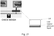
- Figure 21 shows one embodiment of the weight check function of the instruments of the present invention.
- An IPC mass container can be positioned under the print head as close to the print head as possible to minimize the loss of material due to vaporization.
- the IPC container can contain a low vapor pressure liquid into which a predetermined amount of the coating material can be dispensed from the print head. Once the print head material is dispensed into the low vapor pressure liquid in the IPC container the lid to the container is closed and the container is transferred to a weigh station. Then a next patch tray can be loaded and the coating of the microprojection array can continue.
- the IPC container is placed on a balance for less than 50 second, optimally less than 30 second and the IPC container can be removed from the balance and prepared for the next print head weight check.
- the IPC container need not be emptied as the difference in mass from one weighing to the next will provide information as to the amount of coating material dispensed.
- Printing a single drop from each nozzle of a two dimensional nozzle array with a single piezo pulse onto a hydrophobic surface will check the alignment of each nozzle assuming the print head is as physically close to the hydrophobic substrate as possible without disrupting the drop (e.g. about 100 ⁇ m for a drop diameter of about 80 ⁇ m).
- the drop velocity can be determined by moving the hydrophobic substrate while printing a single pulsed array.
- Printing separate arrays with the substrate moving sequentially in orthogonal directions and comparing the results to those obtained with a static array can be used to assess drop velocity and angle uniformity. If the velocity of the drop from the nozzle was less than that predicted the spacing between the drops would be different. The tolerance could be determined in this fashion and a pass/fail criteria could be applied to the device.
- the approaches above with respect to the weight of the drop could be applied to measure a variety of characteristics of the solution such as those listed above.
- the solution characteristic could either be measured inline or offline.
- Coating a pharmaceutical or biological material onto a device such as a microprojection array presents unique challenges that are not encountered in a non-aseptic environment. Often time pharmaceuticals or biologicals cannot be sterilized and thus must be manufactured in an enclosed controlled environment.
- Commercial print heads are required to be periodically wiped to clean the head and to prevent wetting of the nozzle plate. Alternatively the print heads can be capped to prevent the nozzles from being clogged by dried printer ink if the print process is halted. In aseptic printing of biological material neither of these processes is desirable as there is a risk of contamination or the generation of particles that could clog the nozzles.
- the use of devices to clean the print head and to interrupt printing in an aseptic environment would complicate the process and would risk the integrity of the product.
- the methods of the present invention may, however, require that printing be halted for a period of time.
- the methods of the present invention provide a solution where wiping or capping the nozzles are not required and thus provide a contact-free method of printing or coating which is compatible with aseptic or GMP manufacturing.
- the nozzle plate is filled with fluid and due to capillary action and a liquid-air interface a meniscus is formed at the nozzle exit.
- the solvent in the fluid e.g. water
- the solute remains behind at the nozzle exit.
- the solute accumulates at the nozzle exit thereby clogging the exit and impairing the ability to form liquid droplets from the nozzle during the jetting process.
- humectants may be added to the fluid which enables the solute to remain "soft", even as the solvent evaporates. The addition of humectants into pharmaceutical or biological material is not desirable.
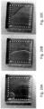
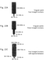
- FIG. 22A , B, C demonstrate three different nozzle geometries in which only Figure 22C has a continuous internal profile.
- the nozzles in Figure 22A and 22B have nozzle geometries with singularity points.
- Figure 23A and 23B are representations of the nozzle plate and descender plate where there is a discontinuous internal profile and a continuous internal profile respectively.
- the continuous profile of the nozzle is less than 100 ⁇ m.
- the contact line of the meniscus retracts into the nozzle plate internal profile and contacts the singularity point leading to either stopped contact line movement or disrupted contact line movement.
- the contact line stops at singular points the concave shaped meniscus may retract so far into the nozzle that before the centre of the meniscus oscillates back to the nozzle the nozzle is already closed. This results in the trapping of air inside the nozzle which can lead to the failure of dispensing of the fluid.
- the contact line is disrupted at the singular points within the nozzle a phenomenon called air-gulping occurs.
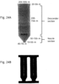
- the nozzle plate can have a thickness of up to 1000 ⁇ m and the nozzle has a continuous internal profile such that the meniscus contact line within the nozzle plate can move up and down with a total travel space of up to 1000 ⁇ m without the risk of trapping bubbles. (See Figures 24A and 24B ).
- the piezo actuating waveform creates the meniscus oscillation.
- a piezo unimorph structure is used to actuate the drop formation process.
- the piezo has a capacitive load of from about 1 to 20 nF and is driven using a waveform with a peak to peak voltage of about -200 V to + 200 V.
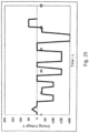
- Figure 25 demonstrates a waveform used to enable meniscus oscillation.
- the meniscus oscillation waveform does not have a high voltage of up to +200 V to create positive pressure inside the pumping chamber to form droplets. Instead, the meniscus oscillation waveform operates mostly in the negative voltage range to create pressure waves in the harmonic frequency of the meniscus oscillation.
- the waveform may take different shapes.
- the frequency of running the waveform described in Figure 25 may be up to 1000Hz.
- Another factor to be considered in the meniscus oscillation waveform is the slew rate which is the rate of changing from one voltage value to another. In one embodiment of the meniscus oscillation waveform the slew rate should be above 150 V/ps. The high slew rate permits the rapid change in the piezo dimension and results in a sudden change in pumping chamber pressure.
- the piezo should have the following characteristics: minimum slew rate of 150 V/ps, capacitive load of up to 20nF, peak current of 3A, internal frequency of the waveform 100Hz and global frequency of the waveform up to 1000Hz.
- the thickness of the pumping chamber is less than 0.3mm. A thinner pumping chamber provides a lower pumping chamber fluid volume and thus less equivalent fluidic capacitance and faster response to fluid pressure changes.
- the nozzle plate can have a thickness of up to 100 ⁇ m or 150 ⁇ m or 200 ⁇ m, or 300 ⁇ m, or 400 ⁇ m, or 500 ⁇ m, or 600 ⁇ m, or 700 ⁇ m, or 800 ⁇ m, or 900 ⁇ m or 1000 ⁇ m.
- the nozzle plate can have a thickness of between about 100 ⁇ m to 1000 ⁇ m, or from about 150 ⁇ m to 1000 ⁇ m, or from about 200 ⁇ m to 1000 ⁇ m or from about 250 ⁇ m to 1000 ⁇ m, or from about 300 ⁇ m to 1000 ⁇ m, or from about 400 ⁇ m to 1000 ⁇ m, or from about 500 ⁇ m to 1000 ⁇ m,or from about 600 ⁇ m to 1000 ⁇ m,or from about 700 ⁇ m to 1000 ⁇ m, or from about 800 ⁇ m to 1000 ⁇ m, or from about 900 ⁇ m to 1000 ⁇ m, or from about 100 ⁇ m to 900 ⁇ m, or from about 150 ⁇ m to 900 ⁇ m, or from about 200 ⁇ m to 900 ⁇ m or from about 250 ⁇ m to 900 ⁇ m, or from about 300 ⁇ m to 900 ⁇ m, or from about 400 ⁇ m to 900 ⁇ m, or from about 500 ⁇ m to 900 ⁇ m, or from about 600 ⁇ m to 900 ⁇ m, or from about 700 ⁇ m to 900 ⁇ m, or from about 800 ⁇ m to 900.
- the greater nozzle plate thickness enables larger meniscus retraction and oscillation well above the nozzle exit (the descender section of the nozzle plate) without the problems associated with air gulping.
- the retracting and oscillation of the meniscus is so large that it enables full material mixing across the liquid-air interface. Full material mixing minimizes equalizes the chemical potential of all molecules at the liquid-air interface to that in the liquid.
- a "tickling" function is provided by the print head device which changes the piezo waveform to allow a drop of fluid material to be formed but not ejected from the nozzle and this function can provide a "bounce" of the meniscus layer for a period of time.
- the geometry of the nozzle can be designed such that that a more thorough mixing of the fluid from the drop meniscus which permits the cessation of printing for an indefinite period of time provided the nozzles are purged prior to the next print cycle.
- the fluid that is "tickled” can be recirculated within the nozzle geometry and dispensing of the fluid from the nozzles may be resumed by reverting back to the print waveform of the piezo.
- the thickness of the nozzle plates in commercial print heads is less than 100 ⁇ m.
- the nozzle plates of the present invention may have a thickness of from about 50 ⁇ m to about 5mm.
- the nozzle plate is from about 200 ⁇ m to about 500 ⁇ m or from about 250 ⁇ m to about 500 ⁇ m or from about or from about 300 ⁇ m to about 500 ⁇ m or from about 350 ⁇ m to about 500 ⁇ m or from about 400 ⁇ m to about 500 ⁇ m or from about 450 ⁇ m to about 500 ⁇ m.
- Increasing the thickness of the nozzle plate provides the ability to create a high retracting meniscus movement into the descender section of the nozzle plate without creating air gulping.
- the retracting meniscus motion is large enough to break down the meniscus contact line at the nozzle thereby creating full fluid material mixing across the entire meniscus surface.
- a thin nozzle plate as in those found in commercial print heads the contact line cannot be fully broken down as this will introduce an air gulping problem and will prevent full fluid material mixing across the entire meniscus.
- a waveform is required to create a negative pressure wave in the pumping chamber and the pressure wave needs to be in harmonic frequency of the meniscus oscillation.
- the formulations of the fluid material that are coated onto the medical devices, such as the microprojection arrays are expensive and it is advantageous to minimize any loss of the material during priming and coating.
- Liquid filling systems for syringes have a significant amount of residual fluid and require a certain level of fluid to maintain filling thereby leading to loss of material.
- the devices of the present invention are designed such that the device can "run dry" and thus minimize the loss of material during the coating process.
- the print head devices of the present invention provide monitoring of the return piezo signal and identification of the waveform changes that occur when there is no fluid resistance between the piezo and the fluid interface. This monitoring and signal identification can detect when the fluid material has been depleted and thus printing can be halted. This method of monitoring and signal identification may also be used to detect partial or full blockage of the print head nozzle plate.
- the print heads/nozzle plates of the present invention may be comprised of two plates in which holes are laser drilled and that are bonded together.
- the top plate has holes that are larger than those in the bottom plate.
- the holes in the top plate can be on the order of from about 2 ⁇ m to 2000 ⁇ m, preferably between about 100 ⁇ to about 250 ⁇ m.
- the bottom plate from which the fluid is ultimately dispensed has holes that correspond to those in the top plate, but the holes are smaller.
- the holes in the bottom plate should be on the order of from about 20 ⁇ m to about 200 ⁇ m or from about 30 ⁇ m to about 200 ⁇ m or from about 40 ⁇ m to about 200 ⁇ m or from about 50 ⁇ m to about 200 ⁇ m or from about 60 ⁇ m to about 200 ⁇ m or from about 70m to about 200 ⁇ m or from about 80 ⁇ m to about 200 ⁇ m or from about 90 ⁇ m to about 200 ⁇ m or from about 100 ⁇ m to about 200 ⁇ m or from about 110 ⁇ m to about 200 ⁇ m or from about 120 ⁇ m to about 200 ⁇ m or from about 130m to about 200 ⁇ m or from about 140 ⁇ m to about 200 ⁇ m or from about 150 ⁇ m to about 200 ⁇ m or from about 160 ⁇ m to about 200 ⁇ m or from about 170 ⁇ m to about 200 ⁇ m or from about 180 ⁇ m to about 200 ⁇ m or from about 190m to about 200 ⁇ m.
- the two plates may be bonded together by the following including but not limited to epoxy or diffusion bonding or laser welding such that the smaller holes in the bottom plate are centred on the larger holes of the top plate.
- the alignment and bonding of the two plates provides a final shape that is capable of flow similar to that obtained with EDM manufactured nozzle plates but the method is faster and less expensive.
- a combination of laser drilling and EDM manufacture may also be used to create the print heads/nozzle plates of the present invention.
- a dry sterile print head can be filled with pharmaceutical or biological fluid material without creating air bubbles that could affect the dispensing of the fluid.
- the print head could be filled with fluid without pre-priming or de-gassing. The fluid flows into a dry sterile print head and automatically flows through without dispensing drops and eliminates any air that could affect drop formation.
- the low end of length of the fluid path inside the print head is on the scale of less than 0.50 mm.
- the length of the fluid path inside the print head may be less than about 0.50mm or less than about 0.45mm or less than about 0.40mm or less than about 0.35mm or less than about 0.30mm or less than about 0.35mm or less than about 0.20mm or less than about 0.15mm or less than about 0.10mm or less than about 0.05mm.
- the length of the fluid path inside the print head may be about 0.05 to 0.50mm, or about 0.05 to 0.45mm or about 0.05 to 0.40mm or about 0.05 to 0.35mm or about 0.05 to 0.30mm, or about 0.05 to 0.25mm or about 0.05 to 0.20mm or about 0.05 to 0.15mm or about 0.05 to 0.10mm, or about 0.10 to about 0.50mm or about 0.10 to 0.45mm or about 0.10 to 0.40mm or about 0.10 to 0.35mm or about 0.10 to 0.30mm, or about 0.10 to 0.25mm or about 0.10 to 0.20mm or about 0.10 to 0.15mm or about 0.15 to about 0.50mm or about 0.15 to 0.45mm or about 0.15 to 0.40mm or about 0.15 to 0.35mm or about 0.15 to 0.30mm, or about 0.15 to 0.25mm or about 0.15 to 0.20mm or about 0.20 to about 0.50mm or about 0.20 to 0.45mm or about 0.20 to 0.40mm or about 0.20 to 0.35mm or about 0.20 to 0.30mm, or about
- Capillary force dominates the wetting behaviour of the three-phase interphase (air-liquid-solid) of the fluid at these dimensions rather than gravitational hydrostatic pressure.
- the wetting behaviour consists of a moving air-liquid-solid contact line.
- the contact line will move in such a fashion that the line occupies the entire space of a fluid path and thus does not trap any air.
- the liquid appears to push out all of the air during the filling of the dry print head.
- the dimension of the individual fluid path length is on the order of less than 0.5 mm. Applying back pressure pushes the fluid into the print head inlet allows the nozzle to be primed such that the nozzles are filled with fluid without air bubbles in the pumping chambers.
- the upper range of the dimension is up to about 20 mm which is the pumping chamber dimension.
- the moving contact line in such a high aspect ratio geometry only in one direction is dominated by the capillary force.
- the liquid flows into the pumping chamber from inlet channels.
- the number of inlet channels can be 1 or 2 or 3 or 4 or 5 or 6 or 7 or 8 or 9 or 10.
- the resulting liquid contact line may form any shape.
- the pumping chamber liquid filling process accompanied with the moving contact line does not rely on any specific mechanism but the random result of a multiplicity of factors including channel flow resistance, surface energy heterogeneity, and local surface topography. This issue is compounded in the print heads of the present invention as the two dimensional nozzle array has multiple outlet channels connected the pumping chamber. The outlets are designed to facilitate recirculation of the printing fluid through the pumping chamber to facilitate fluid mixing and reduce the settling of any materials dissolved or suspended in the fluid.
- the issue could be addressed by vacuuming the print head, but this may lead to boiling the fluid which is also not desirable. Therefore, in preferred embodiments of the print heads of the present invention there is a single channel for fluid to enter the pumping chamber as well as a single channel for fluid to exit the pumping chamber. Such a design eliminates the competition of fluid entering and exiting the pumping chamber and results in a decrease in air entrainment. In addition, in preferred embodiments of the print heads of the present invention between the entering and exiting openings of the pumping chamber all boundaries of the pumping chamber plate around the nozzles have air vents to prevent the contact line from stalling.
- the waveform supplied to drive the PZT acts on the fluid and determines the characteristics of the dispensed fluid drops.
- Drop size is typically 120pL
- a nozzle array is typically 2,500 to 7,500 nozzles per cm 2 .
- the uniformity of drop, drop shape and size, the elimination of satellite drops, the ability to manipulate the fluid interface (meniscus) and therefore the ability to halt printing by oscillation of the meniscus are all controlled by this signal.
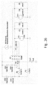
- Two examples of PZT drivers are shown in Figures 26 and 27 .
- PZT driver based on amplifier Apex Microtechnology PA96 provides excellent high-speed control of the PZT with up to a 250V/ps slew rate and a maximum voltage of ⁇ 140150V.
- PZT driver based on amplifier Apex Microtechnology PA96 provides slightly lower performance in terms of speed and distortion, but has superior power dissipation.
- the PA79 amplifier is not able to provide enough current to drive the piezo element therefore the output is boosted by adding a pair of bipolar transistors.
- This circuit can be miniaturized into a small enough footprint as to be included in the print head assembly.
- a controlled signal is generated to drive the PZT and generate drops at the nozzle interface, as the PZT returns to its rest position a second return signal waveform is generated.
- the waveform can be interrogated to determine if the system is running properly. For example, if there is no fluid in the pumping chamber, or if entrapped air is present or if the nozzles blocked monitoring the return signal can determine the problem and appropriate actions can be taken.
- Signal feedback can be achieved with the use of an RLC meter to connect directly to the PZT.
- a 12.5 kHz sine wave can be sent to the PZT.
- the print head oscillates, generates friction, and loses heat.
- the PZT itself as a sensor senses the heat loss, creating a feedback to the RLC meter, i.e., ESR value.
- ESR value if a bubble is present in the pumping chamber, the energy loss is significantly higher.
- the ESR value with and without the bubble existence will be significantly different. If the system were purely a capacitive load, the phase shift of the sine wave signal would be 90 degrees, but since it is not a pure capacitive load, the signal will be close to 90 degrees.
- a second small diameter thin section "sensitive" PZT can be mounted inside the main PZT which has a doughnut-like shape.
- the inner PZT is not driven but records the return wave profile that is monitored for fault conditions. (See Figure 28 ).
- Sterility and cleanliness are important in using inkjet technology to coat pharmaceutical formulations onto devices such as microprojection arrays.
- each component of the print head that comes into contact with the pharmaceutical formulation be made of biocompatible and sterilizable materials such as, but not limited to, stainless steel, glass, Teflon and nylon.
- Biologic materials cannot be terminally sterilized thus the final manufacturing process prior to packing must be conducted in a controlled "clean" environment. This is done within the confines of an isolator that provides a high level of environmental control. All equipment in this space must conform to strict manufacturing and regulatory guidelines.
- printhead devices of the present invention may have one or more components that are disposable.
- the printhead device may be constructed such that the piezoelectric stack actuator is re-usable while the pumping chamber and/or the nozzle plates are/is disposable.
- the printhead device as a whole may be disposable.
- a priming fluid may be similar to the printing fluid with the exception that it may not contain the active biological agent (i.e., vaccine). The purpose of the priming fluid is to fully wet the internal surfaces of the fluidic channels and maintain this bubble free state until the active printing fluid is initiated.
- WFI water for injection
- Sterilization can be performed in a number of ways that are known by those skilled in the art of Pharmaceutical sterilization processes. These methods would typically include (but are not limited to): gamma irradiation, ethylene oxide, aldehyde-based sterilants, and vaporized hydrogen peroxide.
- the print head devices of the present invention may be provided in aseptic packaging.
- the entire print head or a sub-assembly of the device may be supplied in sterile packaging where the print head is filled with a priming solution as described above.
- the print head would not contain a priming solution as it is difficult to validate the complete removal of priming fluid residue prior to printing. It would also be difficult to determine the effect of priming fluid residue on the dispensed formulation.
- the print head devices are then removed from the packaging inside an aseptic enclosure.
- the print heads are mounted in position and supply lines from the bulk solution feed system are connected to the supply ports on the print head. If a priming solution is used a purge cycle can be implemented to prime the solution to be delivered to the substrate (e.g.
- a test cycle may then be run by dispensing solution onto a target.
- a vision system may inspect the test cycle to ensure alignment and positional tolerances are met. For example, if the printhead is located on top of a non-porous polymer substrate and the printhead is actuated for 10 times then in an ideal case, 10 droplets will be dispensed from each nozzle onto the substrate. A line scanning camera would then scan through the substrate where the droplets are printed.
- the scanned image could be analyzed to identify 1) how many nozzles are firing, 2) positioning error (x-, y-, and rotational).
- the relative position of the line scanning camera and the substrate is calibrated prior to above described process.
- the line scanning camera could be driven by a 1-D translational stage, during the scanning process.
- the print head Once initiated, the print head will run continuously at an idle dispense to prevent drying at the nozzle tips.
- the print head may periodically run a purge/clean cycle.
- manufacture of coated microprojection arrays would be per batch where a batch is a single feed lot of solution material (e.g. vaccine) and serial numbers for the print heads used in manufacture.
- the print heads may be single use.
- Figure 29 shows one embodiment of a high speed single print head coating device which comprises an X, Y stage on which microprojection arrays can be mounted, a fiducial camera with LED light, a Z stage to which a rotational print head is attached.
- the entire device can be mounted on a base (e.g. granite base) to ensure stability.
- the translational stage is positioned below the coating height to minimize contamination via particulates generated by the stage movement.
- the stage has a positional accuracy of +/- 1 ⁇ m and can travel of speeds up to 500mm/s with an acceleration of 5000mm/s 2 .
- the design has been optimized such that laminar air flow is optimized to further reduce the risk of particulates interfering in the coating process.
- a high-throughput coating system would provide a complete system control and verification of real time performance of coating a large number of microprojection arrays at high speed. For such a high throughput system it may be necessary to use more than a single print head device. Such a high throughput device could utilize two or three or four or five or six or seven or eight or nine or ten or more print heads.
- One method for aligning the target substrates uses computer vision, image processing and custom sorting algorithms to establish the location data for each microprojection on a microprojection array.
- the data acquired is used to control precise movement coordinates to various motor controllers which use these coordinates to perform minute adjustments such that the microprojection array is oriented to maximize the coating by the nozzles.
- These adjustments are unique from microprojection array to microprojection array and permit the print head to be orthogonal to each microprojection array on a consistent basis regardless of any misalignment or rotation that may have been introduced as the microprojection array is loaded into the printing device.
- the devices and methods of the present invention need to provide high throughput solutions for coating and delivering microprojection arrays.
- This includes having the patches that will be coated in a format where they can be coated and transported easily.
- One of the ways to provide patches that are in a more commercial production friendly form is to interconnect the individual MAP's into compact mats that can be further stacked into a single compact body that requires minimal packaging.
- the mats can be individually manipulated in the aseptic environment, more precisely the mat can be coated as one unit thereby minimizing the instrument footprint, while presenting the MAP already aligned to the printing heads.
- This aspect provides a means to obtain such in-plane cohesion of the patches, while allowing slight individual freedom of movement of the patch out of plane.
- This format enables each patch to be perfectly mated to the coating base.
- the patches can be individually detached from the mat by a pick-and-place robot.
- Some examples of the mat format provide designs which minimal gaps between patches that prevent over-spraying of the printing heads onto the coating base and further contamination of the next mat.
- the MAP design permits the patches to be connected as a mat of parts which provides: cohesive mat allows for the most compact transport volume; reduced risk of particulate generation during transport and handling; eliminates the need for complex support structures and external packing (Syringe tubs); MAP's handled through manufacturing in bulk as a mat rather than individual parts and a cohesive mat structure protects the coating machine contact parts from contamination from print head satellite drops.
- Figures 30-34 provide mat formats for the patches.
- Figure 30 shows a mat with a cohesive design featuring out-of-plane plane insertion dove tail connectors for the mat cohesion.
- Figure 31 shows a mat with a cohesive design featuring out-of-plane plane insertion connectors for the mat cohesion, and cross shaped ended spigot to stack the mats.
- Figure 32 shows a mat with a cohesive design featuring in-plane friction fit connectors for the mat cohesion, and cross shaped ended spigot to stack the mats.
- Figure 33 shows a mat with a strong cohesion of the mats in a compact stack is achieved with a hexagon shape and through spigots.
- Figure 34 shows a mat without guiding shaft (spigot), using instead in-plane friction fit connectors.
- the mats may also take the form of designs in which there is not a physical interlocking of the individual patches but rather the patches are simply butted against one another as shown in Figures 35-37 .
- Patches form tiles that can be stacked to form a very compact block for transport and handling ( Figure 37 ).
- the final packed form would have a moulded tray for a top and bottom cover, shrink wrapped in polyethylene or similar.
- the external packaging and bottom cover tray may be removed for inline sterilization.
- the 1st layer of 100 patches are picked up by a vacuum plate that picks up 100 patches.
- the vacuum plate is then placed under the print head with the projections facing up.
- the patches are presented to the print head on this vacuum plate with no visible gaps in between the patches otherwise a disposable single use tray or cover/ liner would be needed to prevent contamination from "overspray" touching the next load for coated.
- Following coating the whole vacuum plate with coated patches may be removed to a quality control station and the removed for insertion into the patch applicators. Patches may be removed by a system of pneumatic pins positioned below the vacuum plate that enable the patches to be pushed up in any order from the array.
- the vacuum trays are then returned for the next pick up. In one embodiment the stack of 10,000 patches would be ⁇ 300mm high by 100mm square.
- the need for aseptic/sterile conditions for the biological coating of the microprojection arrays is of importance in the pharmaceutical field.
- Having a disposable method of providing fluid to the printer head would provide flexibility in providing aseptic/sterile material for coating the microprojection arrays.
- the fluid to be dispensed by the print head is provided by an integrated supply or feed container that would be part of a print head device.
- An alternative embodiment would include an external fluid source that is not integral to the print head device but rather is remote to the device and fluid can flow from the reservoir to the print head by a variety of means including a series of tubes.
- the base section of the printer body has embedded in it the control software and pressure sensing for the fluid control. Power and connection to the main coating and assembly machine may be accomplished through the spring loaded electrical contacts.
- the fluid flow from the fluid reservoir to the print head may be controlled in a variety of ways.
- the fluid is controlled by on board fluid pumping.
- Figure 38 shows one embodiment of an integrated fluid reservoir that is connected to the print head (3830).
- the reservoir is a bio processing bag which is contained in a injection moulded polymer cover (3831).
- the fluid level of the fluid in the bioprocessing bag can be seen through a transparent window (3832) in the cover which connects the bioprocessing bag to the body of the printer.
- a bar code/ID label (3833) may be attached to the cover such that the unit may be tracked.
- the printer dock (3834) is part of the final coating and assembly device and the connection point to the printer.
- Figure 39 shows another embodiment of the integrated fluid reservoir without a cover to envelope the fluid reservoir.
- the reservoir is a bioprocessing bag (3935) to which a fluid level window (3932) is welded. Otherwise similar reference numerals to those used in Figure 38 are used to denote similar features, albeit increased by 100.
- FIGS 40A and 40B show a detailed perspective of this embodiment of the fluid reservoir.
- the fluid reservoir may have a sterile connector (4041) to connect the fluid reservoir (4040) to an outside source of fluid.
- the reservoir may have a sampling port (4042) where the fluid can be sampled and a vent (4043).
- the reservoir (4040) may have a peristaltic recirculation loop (4044) such that the fluid can be recirculate to maintain homogeneity.
- a clear moulded fluid level window (4032) may be attached via a weld (4036) to the reservoir (4040) to provide a window for monitoring the fluid level within the reservoir, with a hole (4037) being provided to facilitate connection.
- the window can include a rim (4038), which facilitates connection to the printhead.
- the reservoir has pressure control and can be vented to the ambient atmosphere.
- the injected moulded main body may contain embedded electronics, pressure sensors and firmware.
- the printer may rotate in both directions to permit individual alignment of the printer head to each patch.
- a connection dock rotates within the mounting arm.
- Figure 41 is a schematic figure of one embodiment of the integrated fluid reservoir interfacing with the print head. Magnetic retainers (4151) hold the device in place and the flow channels (4152) redirect laminar airflow.
- the printer plate (4153) and the nozzle head (4154) are at the bottom of the device.
- a communications/electric port (4155) is provided to allow the printhead to be powered and controlled.
- Figure 42 is a schematic of the printer connection (4261) which rotates within a printer mounting arm (4234) to align the print head nozzle with the patch and X, Y stage.
- the connector has location magnets (4263), an engagement ramp and communications/electric port (4264) to facilitate connection of the printhead, and alignment of the magnets and communications ports.
- the fluid is controlled by a fluid pump housed in the mounting arm (4334) of the printer operating exposed flexible tubing (4371) from the printer ( Figure 43 ).
- Figure 44 shows an embodiment of the external reservoir which may contain an electromagnetic array (4472) for stirring fluid.
- Mounting re-useable non-contact pumps in the mounting arm is less expensive but not as ergonomic as having the pump(s) in the moulded body of the printer.
- the cost of a non-contact pump, such as a peristaltic or solenoid pump may be expensive for a disposable item.
- a system for controlling operation of the printhead is shown in Figure 45 .
- the system includes the disposable printhead system, a jetting control system, which controls operation of the printhead, and an ancillary system, such as a computer system or similar, which synchronizes operation of the printhead with positional control of the patches.
- the printhead system includes a reservoir 4540, such as a bioprocess bag, coupled to the printhead 4530 via feedlines 4571.
- a recirculation line 4544 is provided to allow fluid to be recirculated through the reservoir 4540 to prevent stagnation, and hence coagulation of fluid.
- feed and recirculation pumps 4581, 4582 which are typically peristaltic pumps including a drive and pump wheel, and which form part of the jetting control system.
- the feed and recirculation pumps 4581, 4582 are driven by signals from respective pump speed controllers 4583, 4584, which are in turn coupled to a microcontroller 4585, which coordinates operation of the jetting control system.
- the microcontroller 4585 receives pressure sensors from a pressure sensor 4586 in the feedline 4571, allowing this to be used to control the feed pump 4581.
- the microcontroller 4585 is also coupled to a sensor 4587, which senses bar code/ID label 4533, allowing the microcontroller 4585 to determine an indication of the fluid being dispensed. This is typically used to access control parameters, used in controlling operation of the pump, for example defining re-circulation requirements, required pressures, PZT operating parameters, or the like.
- the microcontroller 4585 is coupled to a waveform generator 4588, which generates a drive signal, that is amplified by amplifier 4589, before being applied to the PZT element 4590, to cause the fluid to be dispensed.
- signals are received from the ancillary system to trigger operation of the microcontroller 4585, and the waveform generator 4588, so that the ancillary controller can cause fluid to be dispensed, once the patch and printhead are correctly aligned.
- the fluid is fed from the reservoir to the nozzle plate via the feed peristaltic or solenoid pump (4581).
- the pressure sensor (4586) between the nozzle plate and the pump (4581) monitors the fluid pressure to the nozzle plate and engages (switched on) the pump (4581) when fluid is required. The pump is then disengaged (switched off) when the desired limit is reached.
- the pump can also be used to purge the head or the pump can create a negative pressure.
- mixing is used to maintain fluid homogeneity.
- a magnetic stirrer built into the reservoir (bio processing bag) which is driven by a circular array of electromagnets which are embedded in the moulded printer body.
- An alternative method of mixing is performed by a re-circulation pump (4582). The re-circulation pump is less expensive and an easier alternative as typically stirrer options from suppliers are limited to large bag volumes.
- One type of fluid reservoir (4540) is a bio-processing bag which vents to ambient atmosphere via a 0.2um filter.
- the bio-processing bag has a sampling port.
- the reservoir has the following dimensions: Pre-filled Reservoir - 110mm wide x 125mm deep x 250mm tall. Remote Reservoir - 90mm dia x 97mm tall.
- a print head which is pre-filled with the bio-processing bag can be shipped globally in cold chain storage. Once onsite outer packaging is removed and unit is passed into isolator, final layer packaging removed and the print head fitted to the dock fixed to the coating machine. Since the print head is supplied sterile without reservoir, the reservoir can be aseptically filled at the coating site. Both the reservoir and the print head can be assembled on site either aseptically or inside the isolator.
- the sterile printer may be supplied configured for an external supply with supply lines attached. The print head may be brought into the isolator and the supply lines connected to a larger bio-processing supply or external tank. Multiple print heads can be connected to the same supply. Multiple print heads can be used in a large-scale coating and assembly machine or single print heads can be used for smaller desk top units.
- the print head devices of the present invention coat the microprojections of the microprojection array with vaccine antigen formulations.
- the antigens may be derived from pathogenic organisms which include, but are not limited to, viruses, bacteria, fungi parasites, algae and protozoa and amoebae.
- Illustrative viruses include viruses responsible for diseases including, but not limited to, measles, mumps, rubella, poliomyelitis, hepatitis A, B (e.g., GenBank Accession No. E02707), and C (e.g., GenBank Accession No.
- E06890 as well as other hepatitis viruses, influenza, adenovirus (e.g., types 4 and 7), rabies (e.g., GenBank Accession No. M34678), yellow fever, Epstein-Barr virus and other herpesviruses such as papillomavirus, Ebola virus, influenza virus, Japanese encephalitis (e.g., GenBank Accession No. E07883), dengue (e.g., GenBank Accession No.
- HIV human immunodeficiency virus
- Any suitable antigen derived from such viruses are useful in the practice of the present invention.
- illustrative retroviral antigens derived from HIV include, but are not limited to, antigens such as gene products of the gag, pol, and env genes, the Nef protein, reverse transcriptase, and other HIV components.
- hepatitis viral antigens include, but are not limited to, antigens such as the S, M, and L proteins of hepatitis B virus, the pre-S antigen of hepatitis B virus, and other hepatitis, e.g., hepatitis A, B, and C, viral components such as hepatitis C viral RNA.
- influenza viral antigens include; but are not limited to, antigens such as hemagglutinin and neuraminidase and other influenza viral components.
- measles viral antigens include, but are not limited to, antigens such as the measles virus fusion protein and other measles virus components.
- rubella viral antigens include, but are not limited to, antigens such as proteins El and E2 and other rubella virus components; rotaviral antigens such as VP7sc and other rotaviral components.
- cytomegaloviral antigens include, but are not limited to, antigens such as envelope glycoprotein B and other cytomegaloviral antigen components.
- respiratory syncytial viral antigens include antigens such as the RSV fusion protein, the M2 protein and other respiratory syncytial viral antigen components.
- herpes simplex viral antigens include, but are not limited to, antigens such as immediate early proteins, glycoprotein D, and other herpes simplex viral antigen components.
- antigens such as immediate early proteins, glycoprotein D, and other herpes simplex viral antigen components.
- varicella zoster viral antigens include antigens such as 9PI, gpII, and other varicella zoster viral antigen components.
- Non-limiting examples of Japanese encephalitis viral antigens include antigens such as proteins E, M-E, M-E-NS 1, NS 1, NS 1-NS2A, 80%E, and other Japanese encephalitis viral antigen components.
- rabies viral antigens include, but are not limited to, antigens such as rabies glycoprotein, rabies nucleoprotein and other rabies viral antigen components.
- papillomavirus antigens include, but are not limited to, the L1 and L2 capsid proteins as well as the E6/E7 antigens associated with cervical cancers, See Fundamental Virology, Second Edition, eds. Fields, B.N. and Knipe, D.M., 1991, Raven Press , New York, for additional examples of viral antigens.
- fungi include Acremonium spp., Aspergillus spp., Basidiobolus spp., Bipolar is spp., Blastomyces dermatidis, Candida spp., Cladophialophora carrionii.
- Coccoidiodes immitis Conidiobolus spp., Cryptococcus spp., Curvularia spp., Epidermophyton spp., Exophiala jeanselmei, Exserohilum spp., Fonsecaea compacta, Fonsecaea pedrosoi, Fusarium oxysporum, Fusarium solani, Geotrichum candidum, Histoplasma capsulatum var. capsulatum, Histoplasma capsulatum var.
- duboisii Hortaea wasneckii, Lacazia loboi, Lasiodiplodia theobromae, Leptosphaeria senega7ensis, Madurella grisea, Madurella mycetomatis, Malassezia furfur, Microsporum spp., Neotestudina rosatii, Onychocola canadensis, Paracoccidioides brasiliensis, Phialophora verrucosa, Piedraia hortae, Piedra iahortae, Pityriasis versicolor, Pseudallesheria boydii, Pyrenochaeta romeroi, Rhizopus arrhizus, Scopulariopsis brevicaulis, Scytalidiunt dimidiatum, Sporothrix schenckii, Trichophyton spp., Trichosporon spp., Zygomcete fungi
- representative fungal antigens that can be used in the compositions and methods of the present invention include, but are not limited to, candida fungal antigen components; hi stoplasma fungal antigens such as heat shock protein 60 (HSP60) and other histoplasma fungal antigen components; cryptococcal fungal antigens such as capsular polysaccharides and other cryptococcal fungal antigen components; cocci diodes fungal antigens such as spherule antigens and other cocci diodes fungal antigen components; and tinea fungal antigens such as trichophytin and other coccidiodes fungal antigen components.
- candida fungal antigen components such as heat shock protein 60 (HSP60) and other histoplasma fungal antigen components
- cryptococcal fungal antigens such as capsular polysaccharides and other cryptococcal fungal antigen components
- cocci diodes fungal antigens such as spherule antigens and other cocci diodes
- bacteria include bacteria that are responsible for diseases including, but not restricted to, diphtheria (e.g., Corynebacterium diphtheria), pertussis (e.g., Bordetella pertussis, GenBank Accession No. M35274), tetanus (e.g., Clostridium tetani, GenBank Accession No.
- diphtheria e.g., Corynebacterium diphtheria
- pertussis e.g., Bordetella pertussis, GenBank Accession No. M35274
- tetanus e.g., Clostridium tetani, GenBank Accession No.
- tuberculosis e.g., Mycobacterium tuberculosis
- bacterial pneumonias e.g., Haemophilus influenzae.
- cholera e.g., Vibrio cholerae
- anthrax e.g., Bacillus anthracis
- typhoid plague
- shigellosis e.g., Shigella dysenteriae
- botulism e.g., Clostridium botulinum
- salmonellosis e.g., GenBank Accession No. L03833
- peptic ulcers e.g., Helicobacter pylori
- Legionnaire's Disease Lyme disease
- U59487 Other pathogenic bacteria include Escherichia coli, Clostridium perfringens, Pseudomonas aeruginosa, Staphylococcus aureus and Streptococcus pyogenes.
- bacterial antigens which can be used in the compositions and methods of the invention include, but are not limited to: pertussis bacterial antigens such as pertussis toxin, filamentous hemagglutinin, pertactin, F M2, FIM3, adenylate cyclase and other pertussis bacterial antigen components; diphtheria bacterial antigens such as diphtheria toxin or toxoid and other diphtheria bacterial antigen components; tetanus bacterial antigens such as tetanus toxin or toxoid and other tetanus bacterial antigen components, streptococcal bacterial antigens such as M proteins and other streptococcal bacterial antigen components; gram-negative bacilli bacterial antigens such as lipopolysaccharides and other gram-negative bacterial antigen components; Mycobacterium tuberculosis bacterial antigens such as mycolic acid, heat
- protozoa examples include protozoa that are responsible for diseases including, but not limited to, malaria (e.g., GenBank Accession No. X53832), hookworm, onchocerciasis (e.g., GenBank Accession No. M27807), schistosomiasis (e.g., GenBank Accession No. LOS 198), toxoplasmosis, trypanosomiasis, leishmaniasis, giardiasis (GenBank Accession No. M33641), amoebiasis, filariasis (e.g., GenBank Accession No. J03266), borreliosis, and trichinosis.
- malaria e.g., GenBank Accession No. X53832
- hookworm e.g., GenBank Accession No. M27807
- schistosomiasis e.g., GenBank Accession No. LOS 198
- toxoplasmosis trypanos
- protozoal antigens which can be used in the compositions and methods of the invention include, but are not limited to: plasmodium falciparum antigens such as merozoite surface antigens, sporozoite surface antigens, circumsporozoite antigens, gametocyte/gamete surface antigens, blood-stage antigen pf 155/RESA and other plasmodial antigen components; toxoplasma antigens such as SAG-1, p30 and other toxoplasmal antigen components; schistosomae antigens such as glutathione-S-transferase, paramyosin, and other schistosomal antigen components; leishmania major and other leishmaniae antigens such as gp63, lipophosphoglycan and its associated protein and other leishmanial antigen components; and trypanosoma cruzi antigens such as the 75-77kDa antigen, the 56kDa antigen and other trypanosomal
- any indication that a feature is optional is intended provide adequate support (e.g., under 35 U.S.C. 112 or Art. 83 and 84 of EPC) for claims that include closed or exclusive or negative language with reference to the optional feature.
- Exclusive language specifically excludes the particular recited feature from including any additional subject matter. For example, if it is indicated that A can be drug X, such language is intended to provide support for a claim that explicitly specifies that A consists of X alone, or that A does not include any other drugs besides X. "Negative" language explicitly excludes the optional feature itself from the scope of the claims.
- Non-limiting examples of exclusive or negative terms include “only,” “solely,” “consisting of,” “consisting essentially of,” “alone,” “without”, “in the absence of (e.g., other items of the same type, structure and/or function)" "excluding,” “not including”, “not", “cannot,” or any combination and/or variation of such language.
- a dog is intended to include support for one dog, no more than one dog, at least one dog, a plurality of dogs, etc.
- qualifying terms that indicate singularity include “a single”, “one,” “alone”, “only one,” “not more than one”, etc.
- qualifying terms that indicate (potential or actual) plurality include “at least one,” “one or more,” “more than one,” “two or more,” “a multiplicity,” “a plurality,” “any combination of,” “any permutation of,” “any one or more of,” etc.
Landscapes
- Coating Apparatus (AREA)
- Application Of Or Painting With Fluid Materials (AREA)
Claims (17)
- Dispositif pour revêtir un réseau de microprojections avec un fluide, comprenant :(a) un actionneur piézoélectrique (1103) ;(b) une plaque à membrane (1104),(c) une plaque à jeu de déformation (1101) ;(d) une chambre de pompage de restricteur (1102), munie d'installations de ventilation d'air (1805) entourant la chambre de pompage (1102) de telle sorte que lorsque la chambre de pompage (1102) est remplie du fluide, l'air dans chaque zone de la chambre de pompage présente un canal séparé pour s'échapper ; et(e) une plaque à buses (1108), dans lequel la plaque à buses (1108) présente une pluralité de buses et présente une densité de buses comprise entre 1 500 et 3 500 buses par cm2, et dans lequel la plaque à buses comprend des trous de ventilation raccordés à chaque installation de ventilation dans la chambre de pompage, dans laquelle les trous de ventilation sont droits et d'un diamètre plus petit que les buses.
- Dispositif selon la revendication 1, dans lequel l'actionneur piézoélectrique (1103) est activé par un signal et relié de manière opérationnelle à la plaque à membrane (1104) de telle sorte que lorsque l'actionneur piézoélectrique (1103) est activé par le signal, la plaque à membrane (1104) est déformée à travers la plaque à jeu de déformation (1101) de telle sorte que la plaque à membrane (1104) entre en contact avec le fluide dans la chambre de pompage de restricteur (1102) de telle sorte que le fluide est poussé hors de la chambre de pompage de restricteur (1102) et à travers la pluralité de buses de la plaque à buses (1108) et jusque sur le réseau de microprojections.
- Dispositif selon la revendication 1 ou la revendication 2, dans lequel l'actionneur piézoélectrique (1103) est lié à la plaque à membrane (1104) pour former un premier sous-ensemble et dans lequel la plaque à jeu de déformation (1101) et la chambre de pompage de restricteur (1102) et la plaque à buses (1108) sont liées ensemble pour former un second sous-ensemble, et le premier sous-ensemble et le second sous-ensemble sont liés ensemble pour former le dispositif.
- Dispositif selon l'une quelconque des revendications 1 à 3, dans lequel l'actionneur piézoélectrique (1103) est au moins un parmi :(a) un actionneur de pile piézoélectrique ; et,(b) un actionneur unimorphe piézoélectrique.
- Dispositif selon l'une quelconque des revendications 1 à 4, dans lequel la chambre de pompage de restricteur (1102) comprend une entrée de fluide et une sortie de fluide.
- Dispositif selon l'une quelconque des revendications 1 à 5, dans lequel la chambre de pompage de restricteur (1102) comprend en outre un ou plusieurs restricteurs.
- Dispositif selon l'une quelconque des revendications 1 à 6, dans lequel la plaque à buses (1108) inclut une pluralité de buses réalisées en un réseau bidimensionnel.
- Dispositif selon l'une quelconque des revendications 1 à 7, dans lequel le dispositif comprend en outre un réservoir de fluide.
- Dispositif pour imprimer simultanément une matière biologique liquide sur deux microprojections ou plus sur un réseau de microprojections, comprenant :(a) une plaque supérieure (1711) comprenant un trou d'entrée unique (1712) et un trou de sortie unique (1713), la plaque supérieure (1711) étant reliée de manière amovible à(b) une plaque de distribution de fluide (1714) comprenant un ou plusieurs réservoirs (1715), la plaque de distribution de fluide (1714) étant reliée de manière amovible à(c) une plaque à membrane piézoélectrique (1718) comprenant un actionneur piézoélectrique et une membrane (1717) située sous l'actionneur piézoélectrique, la membrane (1717) étant déformée lorsque l'actionneur piézoélectrique est activé, la plaque à membrane piézoélectrique (1718) étant reliée de manière amovible à(d) une plaque à jeu de déformation piézoélectrique (1719) qui est reliée de manière amovible à(e) une plaque de chambre de pompage (1720) qui est reliée de manière amovible à(f) une plaque à buses (1721) dans lequel la plaque à buses (1721) présente une pluralité de buses et dans lequel la densité des buses est comprise entre 1 500 et 3 500 buses par cm2 à partir desquelles la matière fluide peut être expulsé jusque sur les deux microprojections ou plus sur un réseau de microprojections.
- Dispositif selon la revendication 9, dans lequel la plaque supérieure (1711), la plaque de distribution de fluide (1714), la plaque à membrane piézoélectrique (1718), la plaque à jeu de déformation piézoélectrique (1719), la plaque de chambre de pompage (1720) et la plaque à buses (1721) sont toutes contenues dans un boîtier.
- Dispositif selon la revendication 9 ou la revendication 10, dans lequel la plaque à buses (1721) présente une épaisseur d'environ 400 à 500 µm.
- Dispositif selon l'une quelconque des revendications 9 à 11, dans lequel la plaque de chambre de pompage (1720) présente une épaisseur inférieure à 0,3 mm.
- Dispositif selon l'une quelconque des revendications 9 à 12, dans lequel la plaque de chambre de pompage (1720) présente deux restricteurs.
- Dispositif selon l'une quelconque des revendications 9 à 13, dans lequel la plaque à buses (1721) est composée de deux plaques incluant une plaque de descente.
- Dispositif selon l'une quelconque des revendications 9 à 14, dans lequel chaque buse délivre une goutte de la matière biologique liquide, dans lequel le volume de la goutte est compris entre 100 et 500 picolitres.
- Dispositif selon l'une quelconque des revendications 9 à 15, comprenant en outre un réservoir et une boucle de recirculation péristaltique dans lequel la matière biologique liquide est remise en circulation.
- Procédé de revêtement de microprojections sur un réseau de microprojections, comprenant les étapes consistant à :a) aligner le dispositif selon l'une quelconque des revendications 1 à 16 sur un réseau de microprojections comprenant une pluralité de microprojections de sorte que chaque buse soit alignée sur des microprojections qui ne sont pas revêtues ; etb) activer l'actionneur piézoélectrique (1103) de telle sorte que la plaque à membrane (1104) pousse du fluide à travers les buses et jusque sur les microprojections de telle sorte que les microprojections soient revêtues.
Priority Applications (1)
| Application Number | Priority Date | Filing Date | Title |
|---|---|---|---|
| EP23199211.6A EP4306803A3 (fr) | 2017-03-31 | 2018-03-29 | Dispositif et procédé de revêtement de surfaces |
Applications Claiming Priority (2)
| Application Number | Priority Date | Filing Date | Title |
|---|---|---|---|
| US201762601809P | 2017-03-31 | 2017-03-31 | |
| PCT/AU2018/050298 WO2018176102A1 (fr) | 2017-03-31 | 2018-03-29 | Dispositif et procédé de revêtement de surfaces |
Related Child Applications (1)
| Application Number | Title | Priority Date | Filing Date |
|---|---|---|---|
| EP23199211.6A Division EP4306803A3 (fr) | 2017-03-31 | 2018-03-29 | Dispositif et procédé de revêtement de surfaces |
Publications (3)
| Publication Number | Publication Date |
|---|---|
| EP3606760A1 EP3606760A1 (fr) | 2020-02-12 |
| EP3606760A4 EP3606760A4 (fr) | 2020-12-30 |
| EP3606760B1 true EP3606760B1 (fr) | 2023-09-27 |
Family
ID=63673871
Family Applications (2)
| Application Number | Title | Priority Date | Filing Date |
|---|---|---|---|
| EP18776793.4A Active EP3606760B1 (fr) | 2017-03-31 | 2018-03-29 | Dispositif et procédé de revêtement de surfaces |
| EP23199211.6A Pending EP4306803A3 (fr) | 2017-03-31 | 2018-03-29 | Dispositif et procédé de revêtement de surfaces |
Family Applications After (1)
| Application Number | Title | Priority Date | Filing Date |
|---|---|---|---|
| EP23199211.6A Pending EP4306803A3 (fr) | 2017-03-31 | 2018-03-29 | Dispositif et procédé de revêtement de surfaces |
Country Status (8)
| Country | Link |
|---|---|
| US (3) | US11254126B2 (fr) |
| EP (2) | EP3606760B1 (fr) |
| JP (3) | JP7152787B2 (fr) |
| CN (2) | CN115923337A (fr) |
| AU (2) | AU2018241251B2 (fr) |
| DK (1) | DK3606760T3 (fr) |
| ES (1) | ES2960937T3 (fr) |
| WO (1) | WO2018176102A1 (fr) |
Families Citing this family (19)
| Publication number | Priority date | Publication date | Assignee | Title |
|---|---|---|---|---|
| GB0402131D0 (en) | 2004-01-30 | 2004-03-03 | Isis Innovation | Delivery method |
| WO2013053022A1 (fr) | 2011-10-12 | 2013-04-18 | The University Of Queensland | Dispositif de distribution |
| AU2016214968B2 (en) | 2015-02-02 | 2021-02-25 | Vaxxas Pty Limited | Microprojection array applicator and method |
| WO2017045031A1 (fr) | 2015-09-18 | 2017-03-23 | Vaxxas Pty Limited | Réseaux de micro-saillies comportant des micro-saillies ayant des profils à surface élevée |
| EP3355981B1 (fr) | 2015-09-28 | 2025-11-19 | Vaxxas Pty Limited | Réseau de microsaillies ayant des propriétés de pénétration de la peau améliorées et procédés associés |
| EP3606760B1 (fr) | 2017-03-31 | 2023-09-27 | Vaxxas Pty Limited | Dispositif et procédé de revêtement de surfaces |
| DE102017110316B4 (de) * | 2017-05-12 | 2021-02-25 | Abb Schweiz Ag | Applikationsgerät zum Beschichten von Bauteilen mit einem Beschichtungsmittel |
| US11175128B2 (en) | 2017-06-13 | 2021-11-16 | Vaxxas Pty Limited | Quality control of substrate coatings |
| US11464957B2 (en) | 2017-08-04 | 2022-10-11 | Vaxxas Pty Limited | Compact high mechanical energy storage and low trigger force actuator for the delivery of microprojection array patches (MAP) |
| DE102017122495A1 (de) | 2017-09-27 | 2019-03-28 | Dürr Systems Ag | Applikator mit einem geringen Düsenabstand |
| DE102017122493A1 (de) * | 2017-09-27 | 2019-03-28 | Dürr Systems Ag | Applikator mit geringem Düsenabstand |
| CN109869302B (zh) * | 2019-04-04 | 2024-10-11 | 常州威图流体科技有限公司 | 一种垂直支承微型压电泵 |
| FR3096012B1 (fr) * | 2019-05-17 | 2021-04-16 | A Raymond Et Cie | système de distribution d’un fluide pour véhicule, distributeur fluidique associé et procédé d’éjection de fluide utilisant d’un tel système |
| BR112022022039A2 (pt) | 2020-04-28 | 2022-12-13 | Ticona Llc | Conjunto de microagulhas |
| CN111980886B (zh) * | 2020-09-21 | 2024-12-20 | 常州威图流体科技有限公司 | 一种压电微泵支承结构及气体控制装置 |
| WO2024102992A2 (fr) * | 2022-11-10 | 2024-05-16 | Albert Kim | Solides platoniques piézoélectriques imprimables en 3d pour alimentation ultrasonore omnidirectionnelle d'implants miniatures |
| DE102023208320A1 (de) * | 2023-08-30 | 2025-03-06 | Biofluidix Gmbh | Mikrodosiervorrichtung und Verfahren zum Abgeben von Tropfen aus einer Vielzahl von Düsen |
| WO2025199580A1 (fr) * | 2024-03-29 | 2025-10-02 | Vaxxas Pty Limited | Réseaux de microprojections |
| WO2025242695A1 (fr) | 2024-05-21 | 2025-11-27 | Stamford Devices Limited | Plaque d'ouverture de nébuliseur et procédé de fabrication |
Family Cites Families (275)
| Publication number | Priority date | Publication date | Assignee | Title |
|---|---|---|---|---|
| US2213830A (en) | 1938-12-10 | 1940-09-03 | Anastasi John Joseph | Suturing and ligating instrument |
| US2881500A (en) | 1958-07-03 | 1959-04-14 | Charles W Furness | Corneal clamp |
| EP0139286B1 (fr) | 1983-10-14 | 1991-08-21 | Sumitomo Pharmaceuticals Company, Limited | Préparation à libération prolongée de longue durée |
| US4702799A (en) | 1985-09-03 | 1987-10-27 | Nestec S.A. | Dryer and drying method |
| US5017007A (en) | 1989-07-27 | 1991-05-21 | Milne Christopher G | Apparatus and microbase for surface-enhanced raman spectroscopy system and method for producing same |
| AU650249B2 (en) | 1989-11-03 | 1994-06-16 | Immulogic Pharmaceutical Corporation | A human T cell reactive feline protein (TRFP) isolated from house dust and uses therefor |
| US5201992A (en) | 1990-07-12 | 1993-04-13 | Bell Communications Research, Inc. | Method for making tapered microminiature silicon structures |
| US5527288A (en) | 1990-12-13 | 1996-06-18 | Elan Medical Technologies Limited | Intradermal drug delivery device and method for intradermal delivery of drugs |
| US5657138A (en) | 1991-10-13 | 1997-08-12 | Lewis; Aaron | Generating defined structures on materials using combined optical technologies for transforming the processing beam |
| WO1994024281A1 (fr) | 1993-04-14 | 1994-10-27 | Immulogic Pharmaceutical Corporation | Epitopes de lymphocytes t des principaux allergenes de dermatophagoides (acariens detriticoles) |
| AT397458B (de) | 1992-09-25 | 1994-04-25 | Avl Verbrennungskraft Messtech | Sensoranordnung |
| US5461482A (en) * | 1993-04-30 | 1995-10-24 | Hewlett-Packard Company | Electrical interconnect system for a printer |
| US5449064A (en) | 1994-03-03 | 1995-09-12 | University Of Kansas | On-line interface and valve for capillary electophoresis system |
| US5457041A (en) | 1994-03-25 | 1995-10-10 | Science Applications International Corporation | Needle array and method of introducing biological substances into living cells using the needle array |
| US5611806A (en) | 1994-05-23 | 1997-03-18 | Samsung Electro-Mechanics Co., Ltd. | Skin perforating device for transdermal medication |
| AUPM873294A0 (en) | 1994-10-12 | 1994-11-03 | Csl Limited | Saponin preparations and use thereof in iscoms |
| US5499474A (en) | 1994-11-28 | 1996-03-19 | Knooihuizen; Louis D. | Method and apparatus for liquid application |
| JP3366146B2 (ja) * | 1995-03-06 | 2003-01-14 | セイコーエプソン株式会社 | インク噴射ヘッド |
| WO1996037256A1 (fr) | 1995-05-22 | 1996-11-28 | Silicon Microdevices, Inc. | Timbre micromecanique pour ameliorer l'administration de composes a travers la peau |
| US6969635B2 (en) | 2000-12-07 | 2005-11-29 | Reflectivity, Inc. | Methods for depositing, releasing and packaging micro-electromechanical devices on wafer substrates |
| EP0914178B1 (fr) | 1996-06-18 | 2003-03-12 | Alza Corporation | Dispositif d'amelioration d'apport ou d'echantillonnage d'agents transdermiques |
| CN1177543A (zh) * | 1996-08-27 | 1998-04-01 | 托帕兹技术有限公司 | 喷墨打印头设备 |
| CA2217134A1 (fr) | 1996-10-09 | 1998-04-09 | Sumitomo Pharmaceuticals Co., Ltd. | Formulation a liberation-retard |
| AU722574B2 (en) | 1996-12-20 | 2000-08-10 | Alza Corporation | Device and method for enhancing transdermal agent flux |
| WO1998028038A1 (fr) | 1996-12-24 | 1998-07-02 | Alza Corporation | Procede et dispositif de regulation du cycle reproducteur des mammiferes |
| US5859937A (en) | 1997-04-04 | 1999-01-12 | Neomecs Incorporated | Minimally invasive sensor |
| KR100219848B1 (ko) | 1997-04-22 | 1999-09-01 | 이종수 | 구조물의 강도분석 방법 및 장치 |
| US5928207A (en) | 1997-06-30 | 1999-07-27 | The Regents Of The University Of California | Microneedle with isotropically etched tip, and method of fabricating such a device |
| EP1002091B1 (fr) | 1997-07-09 | 2012-02-29 | Coridon Pty Limited | Sequence d'acides nucleiques et procede pour exprimer, de maniere selective, une proteine dans une cellule ou un tissu cible |
| AUPP807899A0 (en) | 1999-01-08 | 1999-02-04 | University Of Queensland, The | Codon utilization |
| US5943075A (en) * | 1997-08-07 | 1999-08-24 | The Board Of Trustees Of The Leland Stanford Junior University | Universal fluid droplet ejector |
| NL1008315C2 (nl) | 1998-02-16 | 1999-08-25 | Stichting Fund Ond Material | Met Si-chip geïntegreerde microdialyse-sonde. |
| EP1056834A2 (fr) | 1998-02-20 | 2000-12-06 | The Rockefeller University | Presentation des antigenes aux lymphocytes t au moyen de cellules d'apoptose |
| US5870806A (en) | 1998-03-18 | 1999-02-16 | Black, Jr.; Robert P. | Bistable member for ejecting snap fastener and spring latch assemblies |
| JP3372862B2 (ja) | 1998-03-25 | 2003-02-04 | 株式会社日立製作所 | 生体液の質量分析装置 |
| US6503231B1 (en) | 1998-06-10 | 2003-01-07 | Georgia Tech Research Corporation | Microneedle device for transport of molecules across tissue |
| WO1999064580A1 (fr) | 1998-06-10 | 1999-12-16 | Georgia Tech Research Corporation | Dispositifs a microaiguilles et procedes de fabrication et d'utilisation correspondants |
| GB9815819D0 (en) | 1998-07-22 | 1998-09-16 | Secr Defence | Transferring materials into cells and a microneedle array |
| US6004815A (en) | 1998-08-13 | 1999-12-21 | The Regents Of The University Of California | Bacteria expressing nonsecreted cytolysin as intracellular microbial delivery vehicles to eukaryotic cells |
| US7048723B1 (en) | 1998-09-18 | 2006-05-23 | The University Of Utah Research Foundation | Surface micromachined microneedles |
| US6414501B2 (en) | 1998-10-01 | 2002-07-02 | Amst Co., Ltd. | Micro cantilever style contact pin structure for wafer probing |
| US6610382B1 (en) | 1998-10-05 | 2003-08-26 | 3M Innovative Properties Company | Friction control article for wet and dry applications |
| EP1163024B1 (fr) | 1999-01-28 | 2003-12-17 | Cyto Pulse Sciences, Inc. | Administration de macromolecules dans des cellules |
| US20020004041A1 (en) | 1999-02-19 | 2002-01-10 | Albert Matthew L. | Methods for abrogating a cellular immune response |
| US6743211B1 (en) | 1999-11-23 | 2004-06-01 | Georgia Tech Research Corporation | Devices and methods for enhanced microneedle penetration of biological barriers |
| EP1187653B1 (fr) | 1999-06-04 | 2010-03-31 | Georgia Tech Research Corporation | Dispositifs permettant d'ameliorer la penetration d'une microaiguille a travers des barrieres tissulaires |
| US6312612B1 (en) | 1999-06-09 | 2001-11-06 | The Procter & Gamble Company | Apparatus and method for manufacturing an intracutaneous microneedle array |
| US6256533B1 (en) | 1999-06-09 | 2001-07-03 | The Procter & Gamble Company | Apparatus and method for using an intracutaneous microneedle array |
| US6299621B1 (en) | 1999-06-18 | 2001-10-09 | Novare Surgical Systems, Inc. | Surgical clamp pads with elastomer impregnated mesh |
| US6233797B1 (en) | 1999-07-13 | 2001-05-22 | Groz Beckert Kg | Felt needle |
| DE19935165A1 (de) | 1999-07-28 | 2001-02-01 | Roche Diagnostics Gmbh | Verfahren und Anordnung zur Konzentrationsbestimmung von Glucose in einer Körperflüssigkeit |
| US6835184B1 (en) | 1999-09-24 | 2004-12-28 | Becton, Dickinson And Company | Method and device for abrading skin |
| AU2573801A (en) | 1999-11-02 | 2001-05-14 | University Of Hawaii | Method for fabricating arrays of micro-needles |
| HK1048604B (en) | 1999-12-10 | 2006-05-04 | Alza Corporation | Device and method for enhancing microprotrusion skin piercing |
| US6558361B1 (en) | 2000-03-09 | 2003-05-06 | Nanopass Ltd. | Systems and methods for the transport of fluids through a biological barrier and production techniques for such systems |
| US6565532B1 (en) | 2000-07-12 | 2003-05-20 | The Procter & Gamble Company | Microneedle apparatus used for marking skin and for dispensing semi-permanent subcutaneous makeup |
| US6537242B1 (en) | 2000-06-06 | 2003-03-25 | Becton, Dickinson And Company | Method and apparatus for enhancing penetration of a member for the intradermal sampling or administration of a substance |
| US6540675B2 (en) | 2000-06-27 | 2003-04-01 | Rosedale Medical, Inc. | Analyte monitor |
| US6589202B1 (en) | 2000-06-29 | 2003-07-08 | Becton Dickinson And Company | Method and apparatus for transdermally sampling or administering a substance to a patient |
| GB0017999D0 (en) | 2000-07-21 | 2000-09-13 | Smithkline Beecham Biolog | Novel device |
| US6749575B2 (en) | 2001-08-20 | 2004-06-15 | Alza Corporation | Method for transdermal nucleic acid sampling |
| US6533949B1 (en) | 2000-08-28 | 2003-03-18 | Nanopass Ltd. | Microneedle structure and production method therefor |
| CA2425312C (fr) | 2000-10-13 | 2010-02-16 | Alza Corporation | Logement pour element a microprotrusions pour applicateur a percussion |
| US7828827B2 (en) | 2002-05-24 | 2010-11-09 | Corium International, Inc. | Method of exfoliation of skin using closely-packed microstructures |
| BR0114909A (pt) | 2000-10-26 | 2004-02-03 | Alza Corp | Dispositivos de distribuição de drogas transdérmicas possuindo microprotuberâncias revestidas |
| US9302903B2 (en) | 2000-12-14 | 2016-04-05 | Georgia Tech Research Corporation | Microneedle devices and production thereof |
| WO2003106964A2 (fr) | 2001-01-10 | 2003-12-24 | Dermal Systems International Inc. | Procedes et dispositifs a haut rendement permettant de doser des analytes dans un echantillon fluidique |
| JP2007216226A (ja) * | 2001-03-14 | 2007-08-30 | Kawamura Inst Of Chem Res | マイクロノズル、その製造方法、スポッティング方法及びスポッタ |
| US6663820B2 (en) | 2001-03-14 | 2003-12-16 | The Procter & Gamble Company | Method of manufacturing microneedle structures using soft lithography and photolithography |
| US6855372B2 (en) | 2001-03-16 | 2005-02-15 | Alza Corporation | Method and apparatus for coating skin piercing microprojections |
| NZ529029A (en) | 2001-04-20 | 2005-07-29 | Alza Corp | Microprojection array having a beneficial agent containing coating |
| US20020193729A1 (en) | 2001-04-20 | 2002-12-19 | Cormier Michel J.N. | Microprojection array immunization patch and method |
| US6591124B2 (en) | 2001-05-11 | 2003-07-08 | The Procter & Gamble Company | Portable interstitial fluid monitoring system |
| DE60213976T2 (de) | 2001-06-08 | 2007-04-26 | Becton Dickinson And Co. | Vorrichtung zur manipulation von nadeln oder polierarray |
| US6767341B2 (en) | 2001-06-13 | 2004-07-27 | Abbott Laboratories | Microneedles for minimally invasive drug delivery |
| US6557849B2 (en) | 2001-06-21 | 2003-05-06 | Da La Rue International | Sheet handling apparatus |
| AT412060B (de) | 2001-07-06 | 2004-09-27 | Schaupp Lukas Dipl Ing Dr Tech | Verfahren zur messung von konzentrationen in lebenden organismen mittels mikrodialyse und und vorrichtung zur durchführung dieses verfahrens |
| US6881203B2 (en) | 2001-09-05 | 2005-04-19 | 3M Innovative Properties Company | Microneedle arrays and methods of manufacturing the same |
| US20040087992A1 (en) | 2002-08-09 | 2004-05-06 | Vladimir Gartstein | Microstructures for delivering a composition cutaneously to skin using rotatable structures |
| US20030135166A1 (en) | 2001-09-28 | 2003-07-17 | Gonnelli Robert R. | Switchable microneedle arrays and systems and methods relating to same |
| JP3835532B2 (ja) * | 2001-10-26 | 2006-10-18 | リコープリンティングシステムズ株式会社 | インクジェット式印刷装置 |
| US20030090558A1 (en) * | 2001-11-15 | 2003-05-15 | Coyle Anthony L. | Package for printhead chip |
| AU2002352978A1 (en) | 2001-11-30 | 2003-06-17 | Alza Corporation | Methods and apparatuses for forming microprojection arrays |
| AU2002357372B2 (en) | 2001-12-20 | 2008-11-20 | Alza Corporation | Skin-piercing microprojections having piercing depth control |
| US6908453B2 (en) | 2002-01-15 | 2005-06-21 | 3M Innovative Properties Company | Microneedle devices and methods of manufacture |
| DE10209763A1 (de) | 2002-03-05 | 2003-10-02 | Bosch Gmbh Robert | Vorrichtung und Verfahren zum anisotropen Plasmaätzen eines Substrates, insbesondere eines Siliziumkörpers |
| WO2003078925A2 (fr) | 2002-03-14 | 2003-09-25 | Taylor Hobson Limited | Appareil de profilage de surfaces |
| US6704996B2 (en) * | 2002-04-30 | 2004-03-16 | Lexmark International, Inc. | Method for making ink jet printheads |
| WO2003092785A1 (fr) | 2002-04-30 | 2003-11-13 | Morteza Shirkhanzadeh | Reseaux de micro-aiguilles comportant un revetement de phosphate de calcium poreux et des agents bioactifs |
| JP3693115B2 (ja) * | 2002-05-13 | 2005-09-07 | セイコーエプソン株式会社 | アクチュエータ装置及び液体噴射ヘッド並びにそれらの検査方法 |
| US6945952B2 (en) | 2002-06-25 | 2005-09-20 | Theraject, Inc. | Solid solution perforator for drug delivery and other applications |
| AU2003243750A1 (en) | 2002-06-25 | 2004-01-06 | Sung-Yun Kwon | Rapidly dissolving micro-perforator for drug delivery and other applications |
| US7052117B2 (en) * | 2002-07-03 | 2006-05-30 | Dimatix, Inc. | Printhead having a thin pre-fired piezoelectric layer |
| KR20120087197A (ko) | 2002-07-19 | 2012-08-06 | 쓰리엠 이노베이티브 프로퍼티즈 컴파니 | 마이크로 니들 장치, 마이크로 니들 장치를 사용하는 방법 및 마이크로 니들 장치를 송출하는 방법 |
| ES2720098T3 (es) | 2002-07-22 | 2019-07-17 | Becton Dickinson Co | Dispositivo de infusión similar a un parche |
| TW200409657A (en) | 2002-08-08 | 2004-06-16 | Alza Corp | Transdermal vaccine delivery device having coated microprotrusions |
| US7081118B2 (en) | 2002-08-22 | 2006-07-25 | Helmut Weber | Medical tool |
| WO2004024224A1 (fr) | 2002-09-16 | 2004-03-25 | Sung-Yun Kwon | Micro-perforateurs solides et leurs procede d'utilisation |
| US7045069B2 (en) | 2002-11-14 | 2006-05-16 | Gennady Ozeryansky | Microfabrication method based on metal matrix composite technology |
| US20040161470A1 (en) | 2002-11-22 | 2004-08-19 | Alexander Andrianov | Preparation of polyphosphazene microspheres |
| WO2004080275A2 (fr) | 2003-03-06 | 2004-09-23 | Applied Medical Resources Corporation | Agrafe a ressort et son procede d'assemblage |
| DE10328730B4 (de) | 2003-06-25 | 2006-08-17 | Micronas Gmbh | Verfahren zum Herstellen eines Microarrays und Vorrichtung zum Versehen eines Trägers für ein Microarray mit Beschichtungsstoffen |
| MXPA06001373A (es) | 2003-08-12 | 2006-05-15 | Becton Dickinson Co | Dispositivo de infusion similar a un parche. |
| CN1897899A (zh) | 2003-10-24 | 2007-01-17 | 阿尔扎公司 | 促进透皮药物传递的装置和方法 |
| US7455654B2 (en) | 2003-10-28 | 2008-11-25 | Alza Corporation | Method and apparatus for reducing the incidence of tobacco use |
| CA2543641A1 (fr) | 2003-10-31 | 2005-05-19 | Alza Corporation | Applicateur a actionnement automatique pour reseau de micro-protuberances |
| WO2005044364A1 (fr) | 2003-11-10 | 2005-05-19 | Agency For Science, Technology And Research | Micro-aiguilles et fabrication de micro-aiguilles |
| WO2005049108A2 (fr) | 2003-11-13 | 2005-06-02 | Alza Corporation | Systeme et methode d'administration transdermique |
| WO2005060621A2 (fr) | 2003-11-21 | 2005-07-07 | The Regents Of The University Of California | Procede et dispositif permettant de perforer une surface afin d'extraire, d'analyser et/ou d'administrer une substance, au moyen de micro-aiguilles |
| IL160033A0 (en) | 2004-01-25 | 2004-06-20 | Transpharma Medical Ltd | Transdermal delivery system for polynucleotides |
| GB0402131D0 (en) | 2004-01-30 | 2004-03-03 | Isis Innovation | Delivery method |
| US7481213B2 (en) * | 2004-02-11 | 2009-01-27 | Hewlett-Packard Development Company, L.P. | Medicament dispenser |
| US20080312669A1 (en) | 2004-03-31 | 2008-12-18 | Vries Luc De | Surgical instrument and method |
| US7591806B2 (en) | 2004-05-18 | 2009-09-22 | Bai Xu | High-aspect-ratio microdevices and methods for transdermal delivery and sampling of active substances |
| EP1773444B1 (fr) | 2004-06-10 | 2017-09-20 | 3M Innovative Properties Company | Dispositif et kit d'application de patch |
| JP2006029881A (ja) | 2004-07-14 | 2006-02-02 | Hitachi High-Technologies Corp | パターン欠陥検査方法および装置 |
| TWI246929B (en) | 2004-07-16 | 2006-01-11 | Ind Tech Res Inst | Microneedle array device and its fabrication method |
| US7316665B2 (en) | 2004-08-25 | 2008-01-08 | Becton, Dickinson And Company | Method and device for the delivery of a substance including a covering |
| US7524430B2 (en) | 2004-09-10 | 2009-04-28 | Lexmark International, Inc. | Fluid ejection device structures and methods therefor |
| KR100580654B1 (ko) * | 2004-10-29 | 2006-05-16 | 삼성전자주식회사 | 노즐 플레이트와 이를 구비한 잉크젯 프린트헤드 및 노즐플레이트의 제조 방법 |
| KR101224257B1 (ko) | 2004-11-18 | 2013-01-18 | 쓰리엠 이노베이티브 프로퍼티즈 컴파니 | 마이크로니들 어레이를 코팅하기 위한 마스킹 방법 |
| JP2008520367A (ja) | 2004-11-18 | 2008-06-19 | スリーエム イノベイティブ プロパティズ カンパニー | 皮膚非接触型のマイクロニードルアレイアプリケータ |
| KR20130026511A (ko) | 2004-11-18 | 2013-03-13 | 쓰리엠 이노베이티브 프로퍼티즈 컴파니 | 로우-프로파일 미세 바늘 어레이 인가 장치 |
| WO2006101459A1 (fr) | 2005-03-23 | 2006-09-28 | Agency For Science, Technology And Research | Micro-aiguilles |
| EP1871459B1 (fr) | 2005-04-07 | 2019-06-19 | 3M Innovative Properties Company | Systeme de captage de retroaction d'un outil |
| US20070270738A1 (en) | 2005-04-25 | 2007-11-22 | Wu Jeffrey M | Method of treating ACNE with stratum corneum piercing patch |
| US20060253078A1 (en) | 2005-04-25 | 2006-11-09 | Wu Jeffrey M | Method of treating skin disorders with stratum corneum piercing device |
| KR101931899B1 (ko) | 2005-05-09 | 2018-12-21 | 테라노스, 인코포레이티드 | 현장진료 유체 시스템 및 그 용도 |
| US8043250B2 (en) | 2005-05-18 | 2011-10-25 | Nanomed Devices, Inc. | High-aspect-ratio microdevices and methods for transdermal delivery and sampling of active substances |
| EP1893130A4 (fr) | 2005-06-17 | 2015-08-26 | Georgia Tech Res Inst | Microstructures revetues et procede de fabrication de celles-ci |
| CA2612307A1 (fr) | 2005-06-21 | 2007-01-04 | Alza Corporation | Procede et dispositif d'application d'une bande continue d'elements a microprojections |
| WO2007002521A2 (fr) | 2005-06-27 | 2007-01-04 | 3M Innovative Properties Company | Dispositif applicateur de matrice de micro-aiguilles et procede d'application d'une telle matrice |
| ATE477833T1 (de) | 2005-06-27 | 2010-09-15 | 3M Innovative Properties Co | Mikronadelkartuschenanordnung |
| US20070027474A1 (en) | 2005-07-15 | 2007-02-01 | Jeffrey Lasner | Pressure limiting forceps |
| CN101227940A (zh) | 2005-07-25 | 2008-07-23 | 纳米技术维多利亚有限公司 | 微阵列装置 |
| CA2629393C (fr) | 2005-09-06 | 2014-06-10 | Theraject, Inc. | Perforateur a solution solide contenant des particules de medicament et/ou des particules a adsorption de medicament |
| US20070078376A1 (en) | 2005-09-30 | 2007-04-05 | Smith Gregory A | Functionalized microneedles transdermal drug delivery systems, devices, and methods |
| EP1957534A1 (fr) | 2005-11-09 | 2008-08-20 | Pharmexa A/S | Vaccins therapeutiques ciblant hmgb1 |
| CA2629193C (fr) | 2005-11-18 | 2016-03-29 | 3M Innovative Properties Company | Compositions pouvant etre revetues, revetements derives de celles-ci et micro-reseaux comprenant de tels revetements |
| WO2007064486A1 (fr) | 2005-11-30 | 2007-06-07 | 3M Innovative Properties Company | Reseaux de microaiguilles et leurs methodes d'utilisation |
| US8308960B2 (en) | 2005-12-14 | 2012-11-13 | Silex Microsystems Ab | Methods for making micro needles and applications thereof |
| US7658728B2 (en) | 2006-01-10 | 2010-02-09 | Yuzhakov Vadim V | Microneedle array, patch, and applicator for transdermal drug delivery |
| GB0600795D0 (en) | 2006-01-16 | 2006-02-22 | Functional Microstructures Ltd | Method of making microneedles |
| JP5028872B2 (ja) | 2006-03-02 | 2012-09-19 | 凸版印刷株式会社 | 針状体の製造方法 |
| US20070224252A1 (en) | 2006-03-27 | 2007-09-27 | Trautman Joseph C | Microprojections with capillary control features and method |
| US9119945B2 (en) | 2006-04-20 | 2015-09-01 | 3M Innovative Properties Company | Device for applying a microneedle array |
| US20070293815A1 (en) | 2006-04-25 | 2007-12-20 | Alza Corporation | Microprojection Array Application with Sculptured Microprojections for High Drug Loading |
| US20070299388A1 (en) | 2006-04-25 | 2007-12-27 | Alza Corporation | Microprojection array application with multilayered microprojection member for high drug loading |
| WO2007127976A2 (fr) | 2006-05-01 | 2007-11-08 | Georgia Tech Research Corporation | Procédé de moulage basé sur des particules |
| US7425465B2 (en) | 2006-05-15 | 2008-09-16 | Fujifilm Diamatix, Inc. | Method of fabricating a multi-post structures on a substrate |
| WO2008011625A2 (fr) | 2006-07-21 | 2008-01-24 | Georgia Tech Researh Corporation | Dispositifs à micro-aiguille(s) et procédés d'administration de médicament ou de retrait de fluide |
| KR100793615B1 (ko) | 2006-07-21 | 2008-01-10 | 연세대학교 산학협력단 | 생분해성 솔리드 마이크로니들 및 이의 제조방법 |
| JPWO2008020632A1 (ja) | 2006-08-18 | 2010-01-07 | 凸版印刷株式会社 | マイクロニードル及びマイクロニードルパッチ |
| WO2008053481A1 (fr) | 2006-11-01 | 2008-05-08 | Svip 6 Llc | Puces à injections |
| JP2008114561A (ja) * | 2006-11-08 | 2008-05-22 | Ricoh Co Ltd | 液体吐出ヘッド、液体吐出装置、画像形成装置 |
| KR20080051342A (ko) | 2006-12-05 | 2008-06-11 | 연세대학교 산학협력단 | 마이크로니들 기기 및 이의 응용방법 |
| EP2104525A4 (fr) | 2006-12-29 | 2010-12-29 | Amir Genosar | Réservoir et appareil hypodermiques d'administration de médicament |
| DE102007002832A1 (de) | 2007-01-19 | 2008-07-24 | Robert Bosch Gmbh | Verfahren zur Herstellung einer Vorrichtung umfassend eine Anordnung von Mikronadeln auf einem Träger und nach diesem Verfahren herstellbare Vorrichtung |
| AU2008209537B2 (en) | 2007-01-22 | 2013-01-31 | Corium Pharma Solutions, Inc. | Applicators for microneedle arrays |
| US8173203B2 (en) * | 2007-02-16 | 2012-05-08 | Brother Kogyo Kabushiki Kaisha | Method of manufacturing piezoelectric actuator and method of manufacturing liquid transporting apparatus |
| US8042916B2 (en) * | 2007-03-31 | 2011-10-25 | Micropoint Biosciences, Inc. | Micromachined fluid ejector array |
| US20090017210A1 (en) | 2007-07-09 | 2009-01-15 | Andrianov Alexander K | Methods and systems for coating a microneedle with a dosage of a biologically active compound |
| US20090041810A1 (en) | 2007-07-09 | 2009-02-12 | Andrianov Alexander K | Immunostimulating polyphosphazene compounds for intradermal immunization |
| US20100121307A1 (en) | 2007-08-24 | 2010-05-13 | Microfabrica Inc. | Microneedles, Microneedle Arrays, Methods for Making, and Transdermal and/or Intradermal Applications |
| US9549746B2 (en) | 2007-09-28 | 2017-01-24 | The Queen's University Of Belfast | Delivery device and method |
| WO2009051147A1 (fr) | 2007-10-18 | 2009-04-23 | Hisamitsu Pharmaceutical Co., Inc. | Dispositif à micro-aiguilles |
| KR101555391B1 (ko) | 2007-11-21 | 2015-09-23 | 가부시키가이샤 바이오세렌택 | 체표 적용 제제 및 체표 적용 제제 보유 시트 |
| GB0724402D0 (en) | 2007-12-14 | 2008-01-30 | Univ Leiden | Microneedle injecting apparatus and method |
| GB0725018D0 (en) | 2007-12-21 | 2008-01-30 | Univ Cardiff | Monitoring system for microneedle delivery |
| US9220678B2 (en) | 2007-12-24 | 2015-12-29 | The University Of Queensland | Coating method |
| CN101214395A (zh) | 2008-01-02 | 2008-07-09 | 西南交通大学 | 一种无机材料表面生物化的方法 |
| EP2247527A4 (fr) | 2008-02-07 | 2014-10-29 | Univ Queensland | Fabrication de timbre transdermique |
| JP5272508B2 (ja) | 2008-05-12 | 2013-08-28 | 凸版印刷株式会社 | 光学シート、バックライトユニット及びディスプレイ装置 |
| AU2009250341A1 (en) | 2008-05-23 | 2009-11-26 | The University Of Queensland | Analyte detection using a needle projection patch |
| CN101297989B (zh) | 2008-06-19 | 2010-06-23 | 上海交通大学 | 基于模压的中空微针批量制备方法 |
| EP2327419B1 (fr) | 2008-06-30 | 2020-05-13 | Hisamitsu Pharmaceutical Co., Inc. | Dispositif de micro-aiguille permettant d'améliorer l'efficacité du vaccin contre l'influenza grâce à l'utilisation dudit dispositif de micro-aiguille |
| JP2010071845A (ja) | 2008-09-19 | 2010-04-02 | Toppan Printing Co Ltd | 検査装置 |
| AU2009304594A1 (en) | 2008-10-16 | 2010-04-22 | The University Of Queensland | A method and associated apparatus for coating projections on a patch assembly |
| JP2010131123A (ja) | 2008-12-03 | 2010-06-17 | Medorekkusu:Kk | マイクロニードルアレイへの薬剤担持法 |
| US20110021996A1 (en) | 2008-12-18 | 2011-01-27 | Miti Systems Inc. | Structure of micro-needle with side channel and manufacturing method thereof |
| US20100156998A1 (en) * | 2008-12-19 | 2010-06-24 | Nobuo Matsumoto | Method and apparatus for printing |
| US8734697B2 (en) | 2008-12-22 | 2014-05-27 | The University Of Queensland | Patch production |
| EP2211089A1 (fr) | 2009-01-26 | 2010-07-28 | GLP German Light Products GmbH | Appareil et procédé pour la génération d'un faisceau lumineux de couleur mixte |
| KR101634838B1 (ko) | 2009-01-30 | 2016-06-29 | 히사미쓰 세이야꾸 가부시키가이샤 | 마이크로 니들 디바이스 |
| WO2012018486A2 (fr) | 2010-07-26 | 2012-02-09 | Seventh Sense Biosystems, Inc. | Distribution et/ou réception rapide de fluides |
| US20120078293A1 (en) | 2009-03-27 | 2012-03-29 | Technion Research & Development Foundation Ltd. | Applicators for patches and adhesives |
| ES2634667T3 (es) | 2009-04-24 | 2017-09-28 | Corium International, Inc. | Métodos para fabricar conjuntos de microproyección |
| TW201039192A (en) | 2009-04-27 | 2010-11-01 | Avermedia Information Inc | Mouse pen and optical receiving module |
| JP2011005422A (ja) * | 2009-06-25 | 2011-01-13 | Kyocera Corp | 液体塗布ヘッドおよびそれを用いた液体塗布装置 |
| WO2011010605A1 (fr) | 2009-07-23 | 2011-01-27 | 久光製薬株式会社 | Réseau de microaiguilles |
| EP2528540A4 (fr) | 2010-01-29 | 2013-11-13 | Icon Medical Corp | Saillies biodégradables sur un dispositif gonflable |
| US8911422B2 (en) | 2010-02-24 | 2014-12-16 | Hisamitsu Pharmaceutical Co., Inc. | Micro-needle device |
| US20110306853A1 (en) | 2010-03-19 | 2011-12-15 | Michael Darryl Black | Body fluid sampling/fluid delivery device |
| EP2563455A4 (fr) | 2010-04-28 | 2014-02-19 | Kimberly Clark Co | Procédé d'augmentation de la perméabilité d'une barrière épithéliale |
| EP2566568B1 (fr) | 2010-05-04 | 2019-04-10 | Corium International, Inc. | Applicateurs pour micro-aiguilles |
| US9199976B2 (en) | 2010-06-01 | 2015-12-01 | The University Of Queensland | Haematopoietic-prostaglandin D2 synthase inhibitors |
| WO2012006677A1 (fr) | 2010-07-14 | 2012-01-19 | The University Of Queensland | Appareil d'application de timbre transdermique |
| CA2815811A1 (fr) | 2010-10-25 | 2012-05-03 | Medrx Co., Ltd. | Microaiguille |
| US9017289B2 (en) | 2010-11-03 | 2015-04-28 | Covidien Lp | Transdermal fluid delivery device |
| JP6082697B2 (ja) | 2010-12-22 | 2017-02-15 | バレリタス, インコーポレイテッド | 極微針パッチアプリケータ |
| US9089677B2 (en) | 2011-01-25 | 2015-07-28 | The Regents Of The University Of California | Transcutaneous multimodal delivery system (TMDS) |
| CN103402496B (zh) | 2011-03-07 | 2016-01-20 | 3M创新有限公司 | 微针装置及方法 |
| ES2542012T3 (es) | 2011-03-07 | 2015-07-29 | 3M Innovative Properties Company | Dispositivos de microagujas y métodos |
| EP2497463A1 (fr) * | 2011-03-09 | 2012-09-12 | Rogier Biemans | Procédé de protection de substances biologiquement actives contre la dénaturation |
| US8512286B2 (en) | 2011-04-18 | 2013-08-20 | Medtronic, Inc. | Detecting a full reservoir of an implantable infusion device |
| US20130158468A1 (en) | 2011-12-19 | 2013-06-20 | Seventh Sense Biosystems, Inc. | Delivering and/or receiving material with respect to a subject surface |
| KR20140034200A (ko) | 2011-04-29 | 2014-03-19 | 세븐쓰 센스 바이오시스템즈, 인크. | 혈액 스폿들 또는 다른 신체 유체들을 수집 및/또는 조작하기 위한 시스템들 및 방법들 |
| CN103874460B (zh) | 2011-04-29 | 2016-06-22 | 第七感生物系统有限公司 | 一种用于从受验者的皮肤接收血液或其它物质的装置 |
| KR20140045986A (ko) | 2011-06-28 | 2014-04-17 | 오츠카 세이야쿠 가부시키가이샤 | 약제 검출 장치 및 약제 검출 방법 |
| JP5870551B2 (ja) * | 2011-08-26 | 2016-03-01 | 大日本印刷株式会社 | マイクロニードルデバイスの製造方法 |
| JP2013043034A (ja) * | 2011-08-26 | 2013-03-04 | Dainippon Printing Co Ltd | マイクロニードルデバイスの製造方法 |
| JP5682513B2 (ja) * | 2011-09-06 | 2015-03-11 | 株式会社村田製作所 | 流体制御装置 |
| KR101975928B1 (ko) * | 2011-09-08 | 2019-05-09 | 삼성전자주식회사 | 프린팅 장치 |
| US9498611B2 (en) | 2011-10-06 | 2016-11-22 | Hisamitsu Pharmaceutical Co., Inc. | Applicator |
| WO2013053022A1 (fr) | 2011-10-12 | 2013-04-18 | The University Of Queensland | Dispositif de distribution |
| CA2851620A1 (fr) | 2011-10-12 | 2013-04-18 | 3M Innovative Properties Company | Systeme integre d'administration d'un reseau de micro-aiguilles |
| US8469490B2 (en) * | 2011-10-26 | 2013-06-25 | Eastman Kodak Company | Ink tank configuration for inkjet printer |
| AU2013212528B2 (en) | 2012-01-24 | 2017-10-05 | International Scientific Pty Ltd | Delivery device |
| EP2833957A4 (fr) | 2012-04-02 | 2016-03-09 | Capricor Therapeutics Inc | Thérapie pour une maladie rénale et/ou une insuffisance cardiaque par perfusion intradermique |
| US20150057604A1 (en) | 2012-04-05 | 2015-02-26 | Hisamitsu Pharmaceutical Co., Inc. | Puncture Device and Method for Manufacturing Same |
| JP2013248299A (ja) | 2012-06-01 | 2013-12-12 | Dainippon Printing Co Ltd | マイクロニードルデバイス |
| JP5795292B2 (ja) * | 2012-09-06 | 2015-10-14 | 富士ゼロックス株式会社 | 液滴吐出装置 |
| WO2014058746A1 (fr) | 2012-10-10 | 2014-04-17 | 3M Innovative Properties Company | Applicateur régulé par une force pour appliquer un dispositif à micro-aiguille sur la peau |
| JP5619940B2 (ja) | 2012-10-31 | 2014-11-05 | 昌毅 明石 | 惰性走行を生かしたエコ運転ができる車輌 |
| CN104027324B (zh) | 2013-03-06 | 2017-12-15 | 中国科学院理化技术研究所 | 一种可溶性微针疫苗贴片及其制备方法 |
| WO2014142135A1 (fr) | 2013-03-12 | 2014-09-18 | 武田薬品工業株式会社 | Timbre à microaiguilles |
| US10624865B2 (en) | 2013-03-14 | 2020-04-21 | Pathak Holdings Llc | Methods, compositions, and devices for drug/live cell microarrays |
| US10384045B2 (en) | 2013-03-15 | 2019-08-20 | Corium, Inc. | Microarray with polymer-free microstructures, methods of making, and methods of use |
| JP6689187B2 (ja) | 2013-03-15 | 2020-04-28 | コリウム, インコーポレイテッド | 複数の衝突微小突起アプリケータおよび使用方法 |
| EP4059450A1 (fr) | 2013-03-15 | 2022-09-21 | Corium, Inc. | Réseaux à microstructures pour l'administration d'agents actifs |
| JP2015036238A (ja) * | 2013-08-15 | 2015-02-23 | 富士フイルム株式会社 | 液体吐出ヘッド及びインクジェット記録装置 |
| RU2720808C2 (ru) | 2013-09-03 | 2020-05-13 | Джорджия Тек Рисёч Корпорейшн | Термостабильные препараты вакцин и микроиглы |
| US9168747B2 (en) * | 2013-10-08 | 2015-10-27 | Xerox Corporation | Multi-layer electroformed nozzle plate with attenuation pockets |
| JP2015109963A (ja) | 2013-10-30 | 2015-06-18 | 帝人株式会社 | 薬剤でコーティングされたマイクロニードルアレイの製造方法 |
| DE102013112404B4 (de) * | 2013-11-12 | 2023-03-16 | ACTEGA Schmid Rhyner AG | Erzeugung von polymeren Partikeln sowie rauer Beschichtungen mittels Ink-Jet-Druck |
| US20160310412A1 (en) | 2013-12-16 | 2016-10-27 | Takeda Pharmaceutical Company Limited | Microneedle |
| JPWO2015152360A1 (ja) | 2014-04-04 | 2017-04-13 | 富士フイルム株式会社 | 不活化全粒子ワクチンを含有するマイクロニードルアレイ製剤およびその投与方法 |
| US20170056637A1 (en) | 2014-05-06 | 2017-03-02 | Mupharma Pty Ltd | Non-invasive agent applicator |
| JP6207459B2 (ja) | 2014-05-15 | 2017-10-04 | 富士フイルム株式会社 | 経皮吸収シートの製造方法 |
| WO2015177976A1 (fr) | 2014-05-20 | 2015-11-26 | 凸版印刷株式会社 | Procédé de production de corps en forme d'aiguille, et corps en forme d'aiguille |
| EP3216482B1 (fr) | 2014-11-06 | 2019-03-20 | Toppan Printing Co., Ltd. | Dispositif d'administration transdermique et procédé de fabrication de dispositif d'administration transdermique |
| WO2016090356A1 (fr) | 2014-12-05 | 2016-06-09 | Fluidigm Canada Inc. | Imagerie par cytométrie de masse |
| JP2016112554A (ja) * | 2014-12-12 | 2016-06-23 | 株式会社リコー | 液滴吐出状態検査方法、液滴吐出装置、及び画像形成装置 |
| JP6001043B2 (ja) | 2014-12-15 | 2016-10-05 | 日本写真印刷株式会社 | マイクロニードルアレイ製造装置及びマイクロニードルアレイの製造方法並びにマイクロニードルアレイを有する製品 |
| CN107206066A (zh) | 2015-01-27 | 2017-09-26 | 3M创新有限公司 | 用于微针疫苗贴剂的含明矾的涂层制剂 |
| AU2016214968B2 (en) | 2015-02-02 | 2021-02-25 | Vaxxas Pty Limited | Microprojection array applicator and method |
| JP6268114B2 (ja) | 2015-03-09 | 2018-01-24 | 富士フイルム株式会社 | マイクロニードルの検査方法 |
| JP6411395B2 (ja) | 2015-03-10 | 2018-10-24 | 富士フイルム株式会社 | 経皮吸収シートの製造方法 |
| JP6487728B2 (ja) | 2015-03-10 | 2019-03-20 | 富士フイルム株式会社 | 計測システム、計測方法及び計測プログラム |
| JP6395694B2 (ja) | 2015-03-10 | 2018-09-26 | 富士フイルム株式会社 | 測定方法及び測定装置及びプログラム |
| WO2016149673A1 (fr) | 2015-03-18 | 2016-09-22 | University Of Pittsburgh - Of The Commonwealth System Of Higher Education | Composés bioactifs conjugués à des substrats de réseaux de micro-aiguilles |
| EP3272387A4 (fr) | 2015-03-18 | 2018-12-12 | Toppan Printing Co., Ltd. | Dispositif d'administration de médicament, et procédé de fabrication de dispositif d'administration de médicament |
| CN104706626B (zh) | 2015-03-25 | 2018-02-23 | 北京化工大学 | 一种便于动物疫苗给药的微针贴片及其制备方法 |
| EP3141388B1 (fr) * | 2015-03-26 | 2018-12-05 | Kyocera Corporation | Élément de trajectoire d'écoulement, tête d'éjection de liquide, appareil d'impression, et procédé pour fabriquer un élément de trajectoire d'écoulement |
| JP2016209389A (ja) | 2015-05-12 | 2016-12-15 | 凸版印刷株式会社 | 針状体原版の製造方法および針状体の製造方法 |
| JP6665028B2 (ja) * | 2015-06-18 | 2020-03-13 | Ntn株式会社 | 形状測定装置およびそれを搭載した塗布装置 |
| KR20180054603A (ko) | 2015-09-17 | 2018-05-24 | 에이오에프 가부시키가이샤 | 마이크로 니들 |
| WO2017045031A1 (fr) | 2015-09-18 | 2017-03-23 | Vaxxas Pty Limited | Réseaux de micro-saillies comportant des micro-saillies ayant des profils à surface élevée |
| EP3355981B1 (fr) | 2015-09-28 | 2025-11-19 | Vaxxas Pty Limited | Réseau de microsaillies ayant des propriétés de pénétration de la peau améliorées et procédés associés |
| EP3185179A1 (fr) | 2015-12-22 | 2017-06-28 | Delphi Technologies, Inc. | Système de capteur optique de véhicule d'imageur multiples |
| KR102064503B1 (ko) | 2015-12-28 | 2020-03-02 | 주식회사 엔도더마 | 경피 흡수용 마이크로구조체 및 이의 제조방법 |
| KR101785930B1 (ko) | 2015-12-30 | 2017-10-16 | 주식회사 쿼드메디슨 | 수분 환경에서 변형 및 변성 억제를 위한 마이크로 니들 및 그 제작 방법 |
| JP2019511255A (ja) | 2016-01-11 | 2019-04-25 | バーンダリ,インク. | マイクロニードル組成物およびそれを使用する方法 |
| DE102016200271A1 (de) | 2016-01-13 | 2017-07-13 | Institut Dr. Foerster Gmbh & Co. Kg | Vorrichtung zur Erzeugung und Messung einer Emission |
| JP2017176460A (ja) | 2016-03-30 | 2017-10-05 | 富士フイルム株式会社 | 針状凸部を有するシートの製造方法 |
| JP6736337B2 (ja) | 2016-04-15 | 2020-08-05 | 富士フイルム株式会社 | マイクロニードルアレイ |
| US11241563B2 (en) | 2016-12-22 | 2022-02-08 | Johnson & Johnson Consumer Inc. | Microneedle arrays and methods for making and using |
| JP6776909B2 (ja) | 2017-01-23 | 2020-10-28 | 株式会社デンソー | 車両用衝突センサ及びその取付構造 |
| EP3606760B1 (fr) | 2017-03-31 | 2023-09-27 | Vaxxas Pty Limited | Dispositif et procédé de revêtement de surfaces |
| JP2018191783A (ja) | 2017-05-15 | 2018-12-06 | 富士フイルム株式会社 | マイクロニードルアレイユニット、および容器 |
| US11175128B2 (en) | 2017-06-13 | 2021-11-16 | Vaxxas Pty Limited | Quality control of substrate coatings |
| US11464957B2 (en) | 2017-08-04 | 2022-10-11 | Vaxxas Pty Limited | Compact high mechanical energy storage and low trigger force actuator for the delivery of microprojection array patches (MAP) |
| EP3664838A4 (fr) | 2017-08-10 | 2021-04-28 | Vaxxas Pty Limited | Revêtement différentiel de microsaillies et de microaiguilles disposées sur des matrices |
| WO2019213218A1 (fr) | 2018-05-01 | 2019-11-07 | Csp Technologies, Inc. | Dispositif d'administration de médicament et son procédé d'utilisation et de fabrication |
| EP4696361A3 (fr) | 2019-02-01 | 2026-04-15 | Massachusetts Institute of Technology | Systèmes et procédés d'injection de liquide |
-
2018
- 2018-03-29 EP EP18776793.4A patent/EP3606760B1/fr active Active
- 2018-03-29 CN CN202211223375.5A patent/CN115923337A/zh active Pending
- 2018-03-29 JP JP2019554394A patent/JP7152787B2/ja active Active
- 2018-03-29 AU AU2018241251A patent/AU2018241251B2/en active Active
- 2018-03-29 DK DK18776793.4T patent/DK3606760T3/da active
- 2018-03-29 WO PCT/AU2018/050298 patent/WO2018176102A1/fr not_active Ceased
- 2018-03-29 ES ES18776793T patent/ES2960937T3/es active Active
- 2018-03-29 CN CN201880036675.8A patent/CN110709250B/zh active Active
- 2018-03-29 EP EP23199211.6A patent/EP4306803A3/fr active Pending
- 2018-04-02 US US15/942,895 patent/US11254126B2/en active Active
-
2022
- 2022-01-07 US US17/571,069 patent/US12179485B2/en active Active
- 2022-05-09 JP JP2022076841A patent/JP7446628B2/ja active Active
-
2024
- 2024-02-20 JP JP2024023547A patent/JP7849897B2/ja active Active
- 2024-09-12 AU AU2024219654A patent/AU2024219654A1/en active Pending
- 2024-11-14 US US18/947,996 patent/US20250065622A1/en active Pending
Also Published As
| Publication number | Publication date |
|---|---|
| AU2018241251B2 (en) | 2024-06-27 |
| JP7152787B2 (ja) | 2022-10-13 |
| CN110709250B (zh) | 2022-10-11 |
| JP7446628B2 (ja) | 2024-03-11 |
| JP2020515407A (ja) | 2020-05-28 |
| US20220126579A1 (en) | 2022-04-28 |
| EP3606760A4 (fr) | 2020-12-30 |
| EP3606760A1 (fr) | 2020-02-12 |
| ES2960937T3 (es) | 2024-03-07 |
| JP2024063053A (ja) | 2024-05-10 |
| US20250065622A1 (en) | 2025-02-27 |
| CN115923337A (zh) | 2023-04-07 |
| WO2018176102A1 (fr) | 2018-10-04 |
| US11254126B2 (en) | 2022-02-22 |
| JP7849897B2 (ja) | 2026-04-22 |
| AU2024219654A1 (en) | 2024-10-03 |
| EP4306803A3 (fr) | 2024-04-10 |
| US20180326726A1 (en) | 2018-11-15 |
| EP4306803A2 (fr) | 2024-01-17 |
| CN110709250A (zh) | 2020-01-17 |
| DK3606760T3 (da) | 2023-11-06 |
| JP2022103267A (ja) | 2022-07-07 |
| US12179485B2 (en) | 2024-12-31 |
| AU2018241251A1 (en) | 2019-10-17 |
Similar Documents
| Publication | Publication Date | Title |
|---|---|---|
| US12179485B2 (en) | Device and method for coating surfaces | |
| US20250108398A1 (en) | Piezoelectric dispenser with a longitudinal transducer and replaceable capillary tube | |
| US20240024457A1 (en) | Differential coating of microprojections and microneedles on arrays | |
| US9068566B2 (en) | Piezoelectric dispenser with a longitudinal transducer and replaceable capillary tube | |
| US20130206857A1 (en) | Piezoelectric dispenser with a longitudinal transducer and replaceable capillary tube | |
| KR100666409B1 (ko) | 처리장치 | |
| US6511849B1 (en) | Microarrays of biological materials | |
| CN113993688B (zh) | 三维增材打印方法 | |
| JP2003121452A (ja) | 液体分注装置 | |
| HK40089888A (zh) | 用於涂覆表面的设备和方法 | |
| JP2002162404A (ja) | 液体分注装置 | |
| JP2002090368A (ja) | マイクロアレイ製造装置および製造方法 |
Legal Events
| Date | Code | Title | Description |
|---|---|---|---|
| STAA | Information on the status of an ep patent application or granted ep patent |
Free format text: STATUS: THE INTERNATIONAL PUBLICATION HAS BEEN MADE |
|
| PUAI | Public reference made under article 153(3) epc to a published international application that has entered the european phase |
Free format text: ORIGINAL CODE: 0009012 |
|
| STAA | Information on the status of an ep patent application or granted ep patent |
Free format text: STATUS: REQUEST FOR EXAMINATION WAS MADE |
|
| 17P | Request for examination filed |
Effective date: 20191031 |
|
| AK | Designated contracting states |
Kind code of ref document: A1 Designated state(s): AL AT BE BG CH CY CZ DE DK EE ES FI FR GB GR HR HU IE IS IT LI LT LU LV MC MK MT NL NO PL PT RO RS SE SI SK SM TR |
|
| AX | Request for extension of the european patent |
Extension state: BA ME |
|
| DAV | Request for validation of the european patent (deleted) | ||
| DAX | Request for extension of the european patent (deleted) | ||
| A4 | Supplementary search report drawn up and despatched |
Effective date: 20201130 |
|
| RIC1 | Information provided on ipc code assigned before grant |
Ipc: B05B 17/06 20060101ALN20201124BHEP Ipc: B05B 15/58 20180101ALN20201124BHEP Ipc: B05B 1/08 20060101AFI20201124BHEP Ipc: A61M 37/00 20060101ALI20201124BHEP Ipc: F04B 43/04 20060101ALI20201124BHEP Ipc: B05B 15/50 20180101ALN20201124BHEP Ipc: B05B 12/08 20060101ALN20201124BHEP |
|
| STAA | Information on the status of an ep patent application or granted ep patent |
Free format text: STATUS: EXAMINATION IS IN PROGRESS |
|
| 17Q | First examination report despatched |
Effective date: 20220629 |
|
| REG | Reference to a national code |
Ref country code: DE Free format text: PREVIOUS MAIN CLASS: B41J0002010000 Ipc: B05B0001080000 Ref country code: DE Ref legal event code: R079 Ref document number: 602018058333 Country of ref document: DE Free format text: PREVIOUS MAIN CLASS: B41J0002010000 Ipc: B05B0001080000 |
|
| GRAP | Despatch of communication of intention to grant a patent |
Free format text: ORIGINAL CODE: EPIDOSNIGR1 |
|
| RIC1 | Information provided on ipc code assigned before grant |
Ipc: B05B 12/08 20060101ALN20230309BHEP Ipc: B05B 17/06 20060101ALN20230309BHEP Ipc: B05B 15/58 20180101ALN20230309BHEP Ipc: B05B 15/50 20180101ALN20230309BHEP Ipc: F04B 43/04 20060101ALI20230309BHEP Ipc: A61M 37/00 20060101ALI20230309BHEP Ipc: B05B 1/08 20060101AFI20230309BHEP |
|
| STAA | Information on the status of an ep patent application or granted ep patent |
Free format text: STATUS: GRANT OF PATENT IS INTENDED |
|
| INTG | Intention to grant announced |
Effective date: 20230413 |
|
| RIN1 | Information on inventor provided before grant (corrected) |
Inventor name: FLAIM, CHRISTOPHER Inventor name: HARRIS, NEIL Inventor name: KANDASAMY, SASIKARAN Inventor name: JUNGER, MICHAEL CARL Inventor name: WANG, XI |
|
| P01 | Opt-out of the competence of the unified patent court (upc) registered |
Effective date: 20230525 |
|
| GRAS | Grant fee paid |
Free format text: ORIGINAL CODE: EPIDOSNIGR3 |
|
| GRAA | (expected) grant |
Free format text: ORIGINAL CODE: 0009210 |
|
| STAA | Information on the status of an ep patent application or granted ep patent |
Free format text: STATUS: THE PATENT HAS BEEN GRANTED |
|
| AK | Designated contracting states |
Kind code of ref document: B1 Designated state(s): AL AT BE BG CH CY CZ DE DK EE ES FI FR GB GR HR HU IE IS IT LI LT LU LV MC MK MT NL NO PL PT RO RS SE SI SK SM TR |
|
| REG | Reference to a national code |
Ref country code: GB Ref legal event code: FG4D |
|
| REG | Reference to a national code |
Ref country code: CH Ref legal event code: EP |
|
| REG | Reference to a national code |
Ref country code: DE Ref legal event code: R096 Ref document number: 602018058333 Country of ref document: DE |
|
| REG | Reference to a national code |
Ref country code: IE Ref legal event code: FG4D |
|
| REG | Reference to a national code |
Ref country code: DK Ref legal event code: T3 Effective date: 20231101 |
|
| REG | Reference to a national code |
Ref country code: SE Ref legal event code: TRGR |
|
| REG | Reference to a national code |
Ref country code: LT Ref legal event code: MG9D |
|
| REG | Reference to a national code |
Ref country code: GR Ref legal event code: EP Ref document number: 20230402330 Country of ref document: GR Effective date: 20240110 |
|
| PG25 | Lapsed in a contracting state [announced via postgrant information from national office to epo] |
Ref country code: RS Free format text: LAPSE BECAUSE OF FAILURE TO SUBMIT A TRANSLATION OF THE DESCRIPTION OR TO PAY THE FEE WITHIN THE PRESCRIBED TIME-LIMIT Effective date: 20230927 Ref country code: NO Free format text: LAPSE BECAUSE OF FAILURE TO SUBMIT A TRANSLATION OF THE DESCRIPTION OR TO PAY THE FEE WITHIN THE PRESCRIBED TIME-LIMIT Effective date: 20231227 Ref country code: LV Free format text: LAPSE BECAUSE OF FAILURE TO SUBMIT A TRANSLATION OF THE DESCRIPTION OR TO PAY THE FEE WITHIN THE PRESCRIBED TIME-LIMIT Effective date: 20230927 Ref country code: LT Free format text: LAPSE BECAUSE OF FAILURE TO SUBMIT A TRANSLATION OF THE DESCRIPTION OR TO PAY THE FEE WITHIN THE PRESCRIBED TIME-LIMIT Effective date: 20230927 Ref country code: FI Free format text: LAPSE BECAUSE OF FAILURE TO SUBMIT A TRANSLATION OF THE DESCRIPTION OR TO PAY THE FEE WITHIN THE PRESCRIBED TIME-LIMIT Effective date: 20230927 |
|
| REG | Reference to a national code |
Ref country code: NL Ref legal event code: MP Effective date: 20230927 |
|
| PG25 | Lapsed in a contracting state [announced via postgrant information from national office to epo] |
Ref country code: NL Free format text: LAPSE BECAUSE OF FAILURE TO SUBMIT A TRANSLATION OF THE DESCRIPTION OR TO PAY THE FEE WITHIN THE PRESCRIBED TIME-LIMIT Effective date: 20230927 |
|
| REG | Reference to a national code |
Ref country code: ES Ref legal event code: FG2A Ref document number: 2960937 Country of ref document: ES Kind code of ref document: T3 Effective date: 20240307 |
|
| REG | Reference to a national code |
Ref country code: AT Ref legal event code: UEP Ref document number: 1614871 Country of ref document: AT Kind code of ref document: T Effective date: 20230927 |
|
| PG25 | Lapsed in a contracting state [announced via postgrant information from national office to epo] |
Ref country code: IS Free format text: LAPSE BECAUSE OF FAILURE TO SUBMIT A TRANSLATION OF THE DESCRIPTION OR TO PAY THE FEE WITHIN THE PRESCRIBED TIME-LIMIT Effective date: 20240127 |
|
| PG25 | Lapsed in a contracting state [announced via postgrant information from national office to epo] |
Ref country code: SM Free format text: LAPSE BECAUSE OF FAILURE TO SUBMIT A TRANSLATION OF THE DESCRIPTION OR TO PAY THE FEE WITHIN THE PRESCRIBED TIME-LIMIT Effective date: 20230927 Ref country code: IS Free format text: LAPSE BECAUSE OF FAILURE TO SUBMIT A TRANSLATION OF THE DESCRIPTION OR TO PAY THE FEE WITHIN THE PRESCRIBED TIME-LIMIT Effective date: 20240127 Ref country code: EE Free format text: LAPSE BECAUSE OF FAILURE TO SUBMIT A TRANSLATION OF THE DESCRIPTION OR TO PAY THE FEE WITHIN THE PRESCRIBED TIME-LIMIT Effective date: 20230927 Ref country code: CZ Free format text: LAPSE BECAUSE OF FAILURE TO SUBMIT A TRANSLATION OF THE DESCRIPTION OR TO PAY THE FEE WITHIN THE PRESCRIBED TIME-LIMIT Effective date: 20230927 Ref country code: SK Free format text: LAPSE BECAUSE OF FAILURE TO SUBMIT A TRANSLATION OF THE DESCRIPTION OR TO PAY THE FEE WITHIN THE PRESCRIBED TIME-LIMIT Effective date: 20230927 Ref country code: PT Free format text: LAPSE BECAUSE OF FAILURE TO SUBMIT A TRANSLATION OF THE DESCRIPTION OR TO PAY THE FEE WITHIN THE PRESCRIBED TIME-LIMIT Effective date: 20240129 |
|
| PG25 | Lapsed in a contracting state [announced via postgrant information from national office to epo] |
Ref country code: PL Free format text: LAPSE BECAUSE OF FAILURE TO SUBMIT A TRANSLATION OF THE DESCRIPTION OR TO PAY THE FEE WITHIN THE PRESCRIBED TIME-LIMIT Effective date: 20230927 |
|
| REG | Reference to a national code |
Ref country code: DE Ref legal event code: R097 Ref document number: 602018058333 Country of ref document: DE |
|
| PLBE | No opposition filed within time limit |
Free format text: ORIGINAL CODE: 0009261 |
|
| STAA | Information on the status of an ep patent application or granted ep patent |
Free format text: STATUS: NO OPPOSITION FILED WITHIN TIME LIMIT |
|
| 26N | No opposition filed |
Effective date: 20240628 |
|
| PG25 | Lapsed in a contracting state [announced via postgrant information from national office to epo] |
Ref country code: SI Free format text: LAPSE BECAUSE OF FAILURE TO SUBMIT A TRANSLATION OF THE DESCRIPTION OR TO PAY THE FEE WITHIN THE PRESCRIBED TIME-LIMIT Effective date: 20230927 |
|
| PG25 | Lapsed in a contracting state [announced via postgrant information from national office to epo] |
Ref country code: SI Free format text: LAPSE BECAUSE OF FAILURE TO SUBMIT A TRANSLATION OF THE DESCRIPTION OR TO PAY THE FEE WITHIN THE PRESCRIBED TIME-LIMIT Effective date: 20230927 |
|
| PG25 | Lapsed in a contracting state [announced via postgrant information from national office to epo] |
Ref country code: BG Free format text: LAPSE BECAUSE OF FAILURE TO SUBMIT A TRANSLATION OF THE DESCRIPTION OR TO PAY THE FEE WITHIN THE PRESCRIBED TIME-LIMIT Effective date: 20230927 |
|
| PG25 | Lapsed in a contracting state [announced via postgrant information from national office to epo] |
Ref country code: LU Free format text: LAPSE BECAUSE OF NON-PAYMENT OF DUE FEES Effective date: 20240329 |
|
| PG25 | Lapsed in a contracting state [announced via postgrant information from national office to epo] |
Ref country code: MC Free format text: LAPSE BECAUSE OF FAILURE TO SUBMIT A TRANSLATION OF THE DESCRIPTION OR TO PAY THE FEE WITHIN THE PRESCRIBED TIME-LIMIT Effective date: 20230927 |
|
| PG25 | Lapsed in a contracting state [announced via postgrant information from national office to epo] |
Ref country code: MC Free format text: LAPSE BECAUSE OF FAILURE TO SUBMIT A TRANSLATION OF THE DESCRIPTION OR TO PAY THE FEE WITHIN THE PRESCRIBED TIME-LIMIT Effective date: 20230927 Ref country code: LU Free format text: LAPSE BECAUSE OF NON-PAYMENT OF DUE FEES Effective date: 20240329 Ref country code: BG Free format text: LAPSE BECAUSE OF FAILURE TO SUBMIT A TRANSLATION OF THE DESCRIPTION OR TO PAY THE FEE WITHIN THE PRESCRIBED TIME-LIMIT Effective date: 20230927 |
|
| PG25 | Lapsed in a contracting state [announced via postgrant information from national office to epo] |
Ref country code: HR Free format text: LAPSE BECAUSE OF FAILURE TO SUBMIT A TRANSLATION OF THE DESCRIPTION OR TO PAY THE FEE WITHIN THE PRESCRIBED TIME-LIMIT Effective date: 20230927 |
|
| PGFP | Annual fee paid to national office [announced via postgrant information from national office to epo] |
Ref country code: GR Payment date: 20250320 Year of fee payment: 8 |
|
| PGFP | Annual fee paid to national office [announced via postgrant information from national office to epo] |
Ref country code: ES Payment date: 20250429 Year of fee payment: 8 |
|
| PGFP | Annual fee paid to national office [announced via postgrant information from national office to epo] |
Ref country code: CH Payment date: 20250401 Year of fee payment: 8 |
|
| PG25 | Lapsed in a contracting state [announced via postgrant information from national office to epo] |
Ref country code: CY Free format text: LAPSE BECAUSE OF FAILURE TO SUBMIT A TRANSLATION OF THE DESCRIPTION OR TO PAY THE FEE WITHIN THE PRESCRIBED TIME-LIMIT; INVALID AB INITIO Effective date: 20180329 |
|
| PG25 | Lapsed in a contracting state [announced via postgrant information from national office to epo] |
Ref country code: HU Free format text: LAPSE BECAUSE OF FAILURE TO SUBMIT A TRANSLATION OF THE DESCRIPTION OR TO PAY THE FEE WITHIN THE PRESCRIBED TIME-LIMIT; INVALID AB INITIO Effective date: 20180329 |
|
| PG25 | Lapsed in a contracting state [announced via postgrant information from national office to epo] |
Ref country code: TR Free format text: LAPSE BECAUSE OF FAILURE TO SUBMIT A TRANSLATION OF THE DESCRIPTION OR TO PAY THE FEE WITHIN THE PRESCRIBED TIME-LIMIT Effective date: 20230927 |
|
| REG | Reference to a national code |
Ref country code: CH Ref legal event code: U11 Free format text: ST27 STATUS EVENT CODE: U-0-0-U10-U11 (AS PROVIDED BY THE NATIONAL OFFICE) Effective date: 20260401 |
|
| PGFP | Annual fee paid to national office [announced via postgrant information from national office to epo] |
Ref country code: SE Payment date: 20260319 Year of fee payment: 9 |
|
| PGFP | Annual fee paid to national office [announced via postgrant information from national office to epo] |
Ref country code: GB Payment date: 20260324 Year of fee payment: 9 |
|
| PGFP | Annual fee paid to national office [announced via postgrant information from national office to epo] |
Ref country code: DE Payment date: 20260319 Year of fee payment: 9 Ref country code: DK Payment date: 20260324 Year of fee payment: 9 Ref country code: IE Payment date: 20260319 Year of fee payment: 9 |
|
| PGFP | Annual fee paid to national office [announced via postgrant information from national office to epo] |
Ref country code: AT Payment date: 20260320 Year of fee payment: 9 |
|
| PGFP | Annual fee paid to national office [announced via postgrant information from national office to epo] |
Ref country code: RO Payment date: 20260323 Year of fee payment: 9 Ref country code: BE Payment date: 20260319 Year of fee payment: 9 Ref country code: IT Payment date: 20260324 Year of fee payment: 9 |
|
| PGFP | Annual fee paid to national office [announced via postgrant information from national office to epo] |
Ref country code: FR Payment date: 20260320 Year of fee payment: 9 |