EP3606821B1 - Fahrzeugsitz - Google Patents
Fahrzeugsitz Download PDFInfo
- Publication number
- EP3606821B1 EP3606821B1 EP17777144.1A EP17777144A EP3606821B1 EP 3606821 B1 EP3606821 B1 EP 3606821B1 EP 17777144 A EP17777144 A EP 17777144A EP 3606821 B1 EP3606821 B1 EP 3606821B1
- Authority
- EP
- European Patent Office
- Prior art keywords
- bench
- section
- thickness
- vehicle seat
- variable thickness
- Prior art date
- Legal status (The legal status is an assumption and is not a legal conclusion. Google has not performed a legal analysis and makes no representation as to the accuracy of the status listed.)
- Active
Links
Images


Classifications
-
- B—PERFORMING OPERATIONS; TRANSPORTING
- B60—VEHICLES IN GENERAL
- B60N—SEATS SPECIALLY ADAPTED FOR VEHICLES; VEHICLE PASSENGER ACCOMMODATION NOT OTHERWISE PROVIDED FOR
- B60N2/00—Seats specially adapted for vehicles; Arrangement or mounting of seats in vehicles
- B60N2/68—Seat frames
- B60N2/686—Panel like structures
-
- B—PERFORMING OPERATIONS; TRANSPORTING
- B64—AIRCRAFT; AVIATION; COSMONAUTICS
- B64D—EQUIPMENT FOR FITTING IN OR TO AIRCRAFT; FLIGHT SUITS; PARACHUTES; ARRANGEMENT OR MOUNTING OF POWER PLANTS OR PROPULSION TRANSMISSIONS IN AIRCRAFT
- B64D11/00—Passenger or crew accommodation; Flight-deck installations not otherwise provided for
- B64D11/06—Arrangements of seats, or adaptations or details specially adapted for aircraft seats
- B64D11/0619—Arrangements of seats, or adaptations or details specially adapted for aircraft seats with energy absorbing means specially adapted for mitigating impact loads for passenger seats, e.g. at a crash
Definitions
- the field of the invention relates to benches with variable thicknesses in seats for aircraft or the like.
- Passenger seats and particularly vehicle or aircraft passenger seats, are designed to ensure passenger safety for various loading conditions including, for example, hard landings and crash conditions. In some instances, regulatory and/or governmental requirements dictate that seats comply with occupant protection/impact tests. The seats must be capable of sustaining loads that cause floor deformation in the vehicle and/or significant inertial loads related to the mass of the occupant.
- Conventional seats (typically designed for two to four occupants) use a framework arrangement with a plurality of frames between occupants and a plurality of support members (cylindrical tubes) that extend laterally and connect to each of the plurality of frames. A seat pan is then attached to the framework (the frames and lateral support members).
- An example of such framework is described in U.S. Application No. 15/314,123 (Pub. No. 2017/0096226 ). Another example is shown in document US2009084925 .
- a vehicle seat is disclosed in claim 1. Further details are disclosed in the dependent claims.
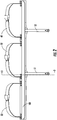
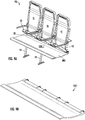
- Figs. 1-8 illustrate embodiments of variable section benches 101 for passenger seats 100 where the variable section bench 101 spans along the full length of the seat 100 in the lateral direction ( see Fig. 1 ) such that the seat 100 may include multiple seat backs 21,31, 41 and belts 22, 32, 42.
- the variable section bench 101 includes a seating surface 101.1 common to all seat backs and has a varying contour and thickness such that the variable section bench 101 is structurally optimized to withstand and transfer all seat loads into the frame assemblies of the seat 100 without the need for separate structural members along the length of the seat 100 ( see Fig. 1 ).
- the seating surface 101.1 may have cushions, layers of foam, or other appropriate objects (not shown) to mimic separation for the portions of the variable section bench 101 for multiple passengers.
- variable section bench 101 may be adapted for use with seats for any number of occupants, including as few as one or as many as ten or more occupants.
- the variable section bench 101 may include an upper layer 102, a middle layer 103, and a lower layer 104 ( see Fig. 8 ).
- the variable section bench 101 may include additional layers based on specific structural attachments for the variable section bench 101 and/or loading conditions.
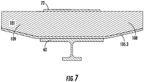
- the variable section bench 101 may interface with at least one frame assembly, where each frame assembly may include a forward frame member 51, 52 and an aft frame member 61, 62.
- the forward frame member 51, 52 may extend through the variable section bench 101 and attach to an upper support platform 71, 72.
- the aft frame member 61 may include an upper portion 63 that includes a contoured surface 64 that corresponds to an appropriate portion of the underside of the variable section bench 101.
- Fig. 3 shows section 3-3 ( see Fig. 2 ), which is a section view looking in the lateral direction of the seat 100.
- Fasteners 11 may extend from the upper support platform 71, 72 through the variable section bench 101 into threaded holes in the upper portion 63 of the aft frame member 61, 62.
- Conventional seats typically require at least one structural member (in addition to the seat pan) extending along the length of the seat with attachment to the various frame assemblies (e.g., attaching to both (1) forward frame member 51/aft frame member 61 and (2) forward frame member 52/aft frame member 62).
- variable section bench 101 incorporate structural features and seat pan components into a single component to eliminate additional structural members extending along the length of the seat with attachment to the various frame assemblies.
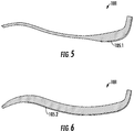
- the variable section bench 101 reduces thickness when moving away from the aft end (where the variable section bench 101 attaches to the seat backs and belts) toward the forward end of the variable section bench 101.
- the thickness of the variable section bench 101 may also change along the length as shown in Fig. 4.
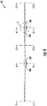
- Fig. 4 is a section view of the entire variable section bench 101 looking aft.
- the variable section bench 101 may have a fore-aft section 5-5 ( see Figs.
- variable section bench 101 may also have an internal section 5.1-5.1 that is approximately halfway between the adjacent frame interface portions, a section 6.1-6.1 for interfacing with a second frame assembly (forward frame member 52 and aft frame member 62), and a section 5.2-5.2 at a cantilevered second end of the seat 100.
- a frame interface portion is fore-aft section 6-6 ( see Figs. 4 and 6 ) for interfacing with a first frame assembly (forward frame member 51 and aft frame member 61).
- the variable section bench 101 may also have an internal section 5.1-5.1 that is approximately halfway between the adjacent frame interface portions, a section 6.1-6.1 for interfacing with a second frame assembly (forward frame member 52 and aft frame member 62), and a section 5.2-5.2 at a cantilevered second end of the seat 100.
- section 5.1-5.1 and section 5.2-5.2 may be similar to section 5-5. However, this is not always the case.
- internal section 5.1-5.1 due to its proximity to the frame attachments at section 6-6 and section 6.1-6.1 may require less material to withstand bending loads and to properly distribute loads compared to at least one of section 5-5 and section 5.2-5.2.
- section 6.1-6.1 may be similar to section 6-6. However, this is not always the case.
- section 6.1-6.1 due to the shorter cantilevered distance of section 5.2-5.2) may require less material to withstand bending loads and to properly distribute loads compared to section 6-6.
- variable section bench 101 is designed to withstand high loads (e.g., shear and bending loads) in the areas near attachment of the frame assemblies.
- high loads e.g., shear and bending loads
- section 6-6 and section 6.1-6.1 may include increased thickness compared to other portions of the variable section bench 101. The increased thickness may be based on local plies of composite material (e.g., woven graphite), metallic features (e.g., machined or sheet metal), composite core material between upper and lower composite face plies, or other relevant features.
- variable section bench 101 may include a thickness reduction 106 on a first side of the interface with a frame at section 6-6 (i.e., with forward frame member 51 and aft frame member 61) and a thickness reduction 107 on a second side of the interface with a frame at section 6-6.
- the thickness reduction 106 on the first side of the frame interface may be symmetric relative to the thickness reduction 107 on the second side of the frame interface, although this is not always the case.
- the variable section bench 101 may include a thickness reduction 108 on a first side of the interface with a frame at section 6.1-6.1 (i.e., with forward frame member 52 and aft frame member 62) and a thickness reduction 109 on a second side of the interface with a frame at section 6.1-6.1.
- the thickness reduction 108 on the first side of the frame interface may be symmetric relative to the thickness reduction 109 on the second side of the frame interface, although this is not always the case.
- the thickness reductions 106-109 each correspond to a series of composite plies that terminate in a stair-step fashion and/or to core that ramps down to a reduced thickness.
- the overall thickness of the variable section bench 101 at section 5-5 may reduce quickly to a minimum thickness when moving away from the aft of the seat 100 ( i.e., near attachment to the seat backs 21, 31, 41). In some embodiments, the section 5-5 reaches a minimum thickness before reaching a halfway point between the aft end and the forward end of the variable section bench 101.
- the reinforcement layer 105 ( see Fig. 8 ) may include a first portion 105.1 at section 5-5 that stops near an aft end of the variable section bench 101.
- the first portion 105.1 extends along the entire length of the variable section bench 101 in the lateral direction and extends approximately 25% from the aft end of the variable section bench 101 (toward the forward end).
- Fig. 6 shows one example of a section 6-6 where the section does not reach a minimum thickness until approximately the forward end of the variable section bench 101.
- a second portion 105.2 of the reinforcement layer 105 may extend a greater distance from the aft end of the variable section bench 101 compared to the first portion 105.1.
- the second portion 105.2 extends approximately 75% from the aft end of the variable section bench 101.
- the reinforcement layer 105 may include a third portion 105.3 aligned with section 6.1-6.1 that is similar to second portion 105.2.
- the variable section bench 101 may include an upper layer 102, a middle layer 103, a lower layer 104, and a reinforcement layer 105.
- at least one of the upper layer 102 and the lower layer 104 have a constant thickness throughout a majority of the entire respective layer.
- the upper layer 102 and the lower layer 104 may each span the approximately entire surface area of the variable section bench 101.
- the middle layer 103 may also span the approximately entire surface area of the variable section bench 101.
- the upper layer 102 and/or the lower layer 104 may be a group of one or more woven and/or unidirectional graphite plies or any other suitable material.
- the middle layer 103 may include at least one woven and/or unidirectional graphite plies, core ( e.g., hard foam core, hex-cell core, crush core, etc. ), a combination thereof, or any other suitable material.
- the variable section bench 101 includes a sandwich panel construction.
- the middle layer 103 may have variable thickness in at least one direction (e.g., the thickness of the middle layer 103 may change when moving from the aft end of the seat toward the forward end and/or may change when moving along the length of the seat 100).
- the variation in thickness between different sections along the length of the variable section bench 101 is primarily due to the differences between the middle layer 103 in the respective areas.
- Figs. 5-8 illustrate the reinforcement layer 105 as disposed below the lower layer 104, in some embodiments, the reinforcement layer 105 is disposed between the middle layer 103 and the lower layer 104.
- Figs. 9A-12 illustrate embodiments of variable section benches 1001 for passenger seats 100
- the variable section bench 1001 includes a seating surface 1001.1 that extends along the full length of the seat 100 in the lateral direction such that the seat 100 may include multiple seat backs 21, 31, 41 and belts 22, 32, 42.
- the seating surface 1001.1 is common to all seat backs and may have cushions, layers of foam, or other appropriate objects (not shown) to mimic separation for the portions of the variable section bench 1001 for multiple passengers.
- the drawings focus on seats 100 that are configured for three occupants; however the variable section bench 1001 may be adapted for use with seats for any number of occupants, including as few as one or as many as ten or more occupants.
- variable section bench 1001 may include an upper layer 1002, a middle layer 1003, and a lower layer 1004 ( see Figs. 10-12 ). In some cases, the variable section bench 1001 may include additional layers based on specific structural attachments for the variable section bench 1001 and/or loading conditions.
- variable section bench 1001 may interface with at least one frame assembly (including a forward frame member 51, 52 and an aft frame member 61, 62) similar to the variable section bench 101.
- the variable section bench 1001 reduces thickness at the forward end of the variable section bench 1001 compared to the aft end (where the variable section bench 1001 attaches to the seat backs and belts).
- the thickness of the variable section bench 1001 may also change along the length as shown in Fig. 10.
- Fig. 10 is a section view of the entire variable section bench 1001 looking aft.
- the variable section bench 1001 may have a fore-aft section 11-11 ( see Figs.
- variable section bench 1001 may also have an internal section 11.1-11.1 that is approximately halfway between the adjacent frame interface portions, a section 12.1-12.1 for interfacing with a second frame assembly (forward frame member 52 and aft frame member 62), and a section 11.2-11.2 at a cantilevered second end of the seat 100.
- at least one of section 11.1-11.1 and section 11.2-11.2 may be similar to section 11-11.
- internal section 11.1-11.1 (due to its proximity to the frame attachments at section 12-12 and section 12.1-12.1) may require less material to withstand bending loads and to properly distribute loads compared to at least one of section 11-11 and section 11.2-11.2.
- section 12.1-12.1 may be similar to section 12-12. However, this is not always the case.
- variable section bench 1001 is designed to withstand high loads (e.g., shear and bending loads) in the areas near attachment of the frame assemblies.
- high loads e.g., shear and bending loads
- section 12-12 and section 12.1-12.1 may include increased thickness compared to other portions of the variable section bench 1001. The increased thickness may be based on local plies of composite material (e.g., woven graphite), metallic features (e.g., machined or sheet metal), composite core material between upper and lower composite face plies, or other relevant features.
- variable section bench 1001 may include a thickness reduction 1006 on a first side of the interface with a frame at section 12-12 ( i.e., with forward frame member 51 and aft frame member 61) and a thickness reduction 1007 on a second side of the interface with a frame at section 12-12. As shown in Fig.
- the thickness reduction 1006 on the first side of the frame interface may extend further from the interface with the frame at section 12-12 (and may reduce in thickness more gradually) than the thickness reduction 1007 on the second side of the frame interface.
- the additional material of thickness reduction 1006 may ensure the variable section bench 1001 can properly distribute loads adjacent to the cantilevered end (near section 11-11) while loads at internal section 11.1-11.1 can be distributed to the frame attachments at both section 12-12 and section 12.1-12.1.
- the thickness reduction 1006 on the first side of the frame interface may be symmetric relative to the thickness reduction 1007 on the second side of the frame interface.
- the variable section bench 1001 may include a thickness reduction 1008 on a first side of the interface with a frame at section 12.1-12.1 (i.e., with forward frame member 52 and aft frame member 62) and a thickness reduction 1009 on a second side of the interface with a frame at section 12.1-12.1.
- the thickness reduction 1008 on the first side of the frame interface may extend further from the interface with the frame at section 12.1-12.1 (and may reduce in thickness more gradually) than the thickness reduction 1009 on the second side of the frame interface.
- the additional material of thickness reduction 1008 may ensure the variable section bench 1001 can properly distribute loads adjacent to the cantilevered end (near section 11.2-11.2) while loads at internal section 11.1-11.1 can be distributed to the frame attachments at both section 12-12 and section 12.1-12.1.
- the thickness reduction 1008 on the first side of the frame interface may be symmetric relative to the thickness reduction 1009 on the second side of the frame interface.
- the thickness reductions 1006-1009 each correspond to a series of composite plies that terminate in a stair-step fashion and/or to core that ramps down to a reduced thickness.
- the overall thickness of the variable section bench 1001 at section 11-11 may reduce quickly to a minimum thickness when moving away from the aft of the seat 100 ( i.e., near attachment to the seat backs 21, 31, 41).
- the section 11-11 reaches a minimum thickness before reaching a halfway point between the aft end and the forward end of the variable section bench 1001.
- Fig. 12 shows one example of a section 12-12 where the section does not reach a minimum thickness until approximately the forward end of the variable section bench 1001.
- the minimum thickness of the variable section bench 1001 at section 11-11 is approximately 0.63 cm to 1.9 cm (0.25 in to 0.75 in) ( see Fig. 11 ).
- the minimum thickness of the variable section bench 1001 at section 11-11 is approximately 1.27 cm (0.5 in).
- the thickness of the variable section bench 1001 at the forward end of section 12-12 may be approximately equal to the minimum thickness of the variable section bench 1001 at section 11-11.
- the thickness at the aft end of the variable section bench 1001 at section 11-11 is approximately 1.9 cm to 3.17 cm (0.75 in to 1.25 in).
- the thickness at the aft end of the variable section bench 1001 at section 11-11 is approximately 2.54 cm (1 in).
- the thickness of the variable section bench 1001 at the aft end of section 12-12 may be approximately equal to the thickness of the variable section bench 1001 at the aft end of section 11-11.
- the maximum thickness of the variable section bench 1001 at section 12-12 or section 12.1-12.1 is approximately 3.17 cm to 6.35 cm (1.5 in to 2.5 in). ( see Fig. 10 ). In certain embodiments, the maximum thickness of the variable section bench 1001 at section 12-12 or section 12.1-12.1 is approximately 5.08 cm (2 in). Accordingly, as shown in a comparison of Figs. 11 and 12 , at a location approximately halfway between the forward end and the aft end, the variable section bench 1001 at section 12-12 is approximately four times the thickness of the variable section bench 1001 at section 11-11 5.08 cm vs 1.27 cm (2 in vs 0.5 in ).
- the variable section bench 1001 may include an upper layer 1002, a middle layer 1003, and a lower layer 1004.
- the variable section bench 1001 may include a reinforcement layer (similar to reinforcement layer 105).
- at least one of the upper layer 1002 and the lower layer 1004 have a constant thickness throughout a majority of the entire respective layer.
- the upper layer 1002 and the lower layer 1004 may each span the approximately entire surface area of the variable section bench 1001.
- the middle layer 103 in some embodiments, may also span the approximately entire surface area of the variable section bench 1001.
- the upper layer 1002 and/or the lower layer 1004 may be a group of one or more woven and/or unidirectional graphite plies or any other suitable material.
- the middle layer 1003 may include at least one woven and/or unidirectional graphite plies, core ( e.g., hard foam core, hex-cell core, crush core, etc. ), a combination thereof, or any other suitable material.
- the variable section bench 1001 includes a sandwich panel construction.
- the middle layer 1003 may have variable thickness in at least one direction (e.g., the thickness of the middle layer 1003 may change when moving from the aft end of the seat toward the forward end and/or may change when moving along the length of the seat 100).
- the variation in thickness between different sections along the length of the variable section bench 1001 e.g., differences between section 11-11 and section 12-12
- the components of the seat 100 may be formed of materials including, but not limited to, aluminum, steel, titanium, carbon composite, graphite composite, polyester, nylon, plastic, thermoplastic, other fabric materials, stainless steel, other plastic or polymer materials, other metallic materials, other composite materials, or other similar materials. Moreover, the components of the seat 100 may be attached to one another via suitable fasteners, which include, but are not limited to, screws, bolts, rivets or other mechanical or chemical fasteners.
Landscapes
- Engineering & Computer Science (AREA)
- Aviation & Aerospace Engineering (AREA)
- Transportation (AREA)
- Mechanical Engineering (AREA)
- Seats For Vehicles (AREA)
Claims (10)
- Fahrzeugsitz (100) mit einer Bank (101) mit variabler Dicke für den Fahrzeugsitz (100), wobei die Bank (101) mit variabler Dicke umfasst:eine obere Schicht (102), eine mittlere Schicht (103) und eine untere Schicht (104);mindestens einen Rahmenschnittstellenabschnitt mit einem Längsschnitt (6-6; 6.1-6.1);mindestens einen überhängenden Abschnitt an einem Ende der Bank (101) mit variabler Dicke mit einem Längsschnitt (5-5; 5.2-5.2); undeine Sitzfläche (101.1), welche sich entlang einer gesamten Länge des Fahrzeugsitzes (100) in seitlicher Richtung für eine Vielzahl von Passagieren erstreckt, wobei der mindestens eine Rahmenschnittstellenabschnitt (6-6; 6.1-6.1) der Bank (101) mit variabler Dicken eine erhöhte Dicke im Vergleich zu dem mindestens einen überhängenden Abschnitt (5-5; 5.2-5.2) aufweist,dadurch gekennzeichnet, dassder mindestens eine Rahmenschnittstellenabschnitt (6-6; 6.1-6.1) zwei Rahmenschnittstellenabschnitte (6-6; 6.1-6.1) umfasst, und die Bank (101) mit variabler Dicke einen inneren Längsschnitt (5.1-5.1) umfassen, der sich ungefähr in der Mitte zwischen den beiden Rahmenschnittstellenabschnitten (6-6; 6.1-6.1) befindet, undan einer Stelle mindestens eines der beiden Rahmenschnittstellenabschnitte (6-6; 6.1-6.1) eine Dicke der Bank (101) mit variabler Dicke eine erste Reduzierung (107, 109) beim Bewegen in Richtung des inneren Längsabschnitts (5.1-5.1) und eine zweite Reduzierung (106, 108) beim Wegbewegen vom inneren Längsschnitt (5.1-5.1) aufweist.
- Fahrzeugsitz nach Anspruch 1, dadurch gekennzeichnet, dass der mindestens eine Rahmenschnittstellenabschnitt (6-6; 6.1-6.1) der Bank (101) mit variabler Dicke ungefähr viermal so dick wie der mindestens eine überhängende Abschnitt (5-5; 5.2-5.2) ist.
- Fahrzeugsitz nach Anspruch 1, dadurch gekennzeichnet, dass die erste und die zweite Reduzierung (106, 107, 108, 109) symmetrisch um die Stelle mindestens eines der beiden Rahmenschnittstellenabschnitte (6-6; 6.1-6.1) sind.
- Fahrzeugsitz nach Anspruch 1, dadurch gekennzeichnet, dass die zweite Reduzierung (106, 108) eine stufenweise Verminderung der Dicke im Vergleich zur ersten Reduzierung (107, 109) umfasst, so dass die erste und die zweite Reduzierung (106, 107, 108, 109) asymmetrisch um die Stelle mindestens eines der beiden Rahmenschnittstellenabschnitte (6-6; 6.1-6.1) sind.
- Fahrzeugsitz nach Anspruch 1, dadurch gekennzeichnet, dass die obere Schicht (102) und die untere Schicht (104) jeweils mehrere Lagen aus gewebtem Verbundmaterial umfassen.
- Fahrzeugsitz nach Anspruch 1, dadurch gekennzeichnet, dass die mittlere Schicht (103) mindestens eine aus gewebtem Verbundmaterial und Verbundschaumkern umfasst.
- Fahrzeugsitz nach Anspruch 1, dadurch gekennzeichnet, dass er ferner eine Verstärkungsschicht (105) umfasst.
- Fahrzeugsitz nach Anspruch 7. dadurch gekennzeichnet, dass die Verstärkungsschicht (105) einen ersten Abschnitt (105.1) umfasst, der sich entlang der gesamten Länge des Fahrzeugsitzes (100) in seitlicher Richtung und sich von hinten ungefähr 25% von einem hinteren Ende der Bank (101) mit variabler Dicke zu einem vorderen Ende der Bank (101) mit variabler Dicke erstreckt.
- Fahrzeugsitz nach Anspruch 7, dadurch gekennzeichnet, dass die Verstärkungsschicht (105) einen zweiten Abschnitt (105.2) umfasst, der mit dem mindestens einen Rahmenschnittstellenabschnitt ausgerichtet ist, und sich ungefähr 75% von einem hinteren Ende der Bank (101) mit variabler Dicke zu einem vorderen Ende der Bank (101) mit variabler Dicke erstreckt.
- Fahrzeugsitz nach Anspruch 1, dadurch gekennzeichnet, dass an einer Stelle des mindestens einen Rahmenschnittstellenabschnitts ein Rahmenelement (51, 52, 61, 62) an einer Bodenfläche der Bank (101) mit variabler Dicke und eine obere Stützplattform (71. 72) an einer Oberseite der Bank (101) mit variabler Dicke derart angeordnet sind, dass sich mehrere Befestigungselemente (11) von der oberen Stützplattform (71, 72) zum Rahmenelement (51, 52, 61, 62) durch eine gesamte Dicke der Bank (101) mit variabler Dicke erstreckt.
Applications Claiming Priority (2)
| Application Number | Priority Date | Filing Date | Title |
|---|---|---|---|
| US201762482341P | 2017-04-06 | 2017-04-06 | |
| PCT/US2017/052211 WO2018186905A1 (en) | 2017-04-06 | 2017-09-19 | Variable section bench for seat |
Publications (2)
| Publication Number | Publication Date |
|---|---|
| EP3606821A1 EP3606821A1 (de) | 2020-02-12 |
| EP3606821B1 true EP3606821B1 (de) | 2021-03-17 |
Family
ID=59974889
Family Applications (1)
| Application Number | Title | Priority Date | Filing Date |
|---|---|---|---|
| EP17777144.1A Active EP3606821B1 (de) | 2017-04-06 | 2017-09-19 | Fahrzeugsitz |
Country Status (4)
| Country | Link |
|---|---|
| US (1) | US11117502B2 (de) |
| EP (1) | EP3606821B1 (de) |
| CN (1) | CN110636970B (de) |
| WO (1) | WO2018186905A1 (de) |
Families Citing this family (1)
| Publication number | Priority date | Publication date | Assignee | Title |
|---|---|---|---|---|
| CN110636970B (zh) * | 2017-04-06 | 2023-09-05 | 赛峰座椅美国有限责任公司 | 座椅的可变截面台 |
Family Cites Families (26)
| Publication number | Priority date | Publication date | Assignee | Title |
|---|---|---|---|---|
| US4526421A (en) * | 1982-09-30 | 1985-07-02 | Ptc Aerospace Inc. | Multi-passenger aircraft seat having composite panel frame |
| GB8331260D0 (en) * | 1983-11-23 | 1983-12-29 | Toll I C | Aircraft seats |
| EP0197167B1 (de) * | 1985-04-04 | 1988-10-26 | Ignaz Vogel GmbH & Co KG, Fahrzeugsitze | Doppel-Fahrgastsitz |
| US5284379A (en) * | 1991-09-04 | 1994-02-08 | The Boeing Company | Convertible aircraft passenger seats |
| DE19534025C1 (de) * | 1995-09-14 | 1996-11-28 | Daimler Benz Aerospace Airbus | Versorgungseinheit für Passagiere, insbesondere in einer Passagierkabine eines Flugzeuges |
| FR2774644B1 (fr) * | 1998-02-12 | 2003-12-05 | Gec Alsthom Transport Sa | Banquette deux places modulable premiere-seconde classe et procede de transformation d'une telle banquette |
| US7954762B2 (en) * | 2006-05-17 | 2011-06-07 | The Boeing Company | Lightweight aircraft passenger seat with composite construction |
| US7493844B2 (en) * | 2006-07-27 | 2009-02-24 | Chad Brian Martin | Vehicle security partition |
| US8205833B2 (en) * | 2006-12-22 | 2012-06-26 | The Boeing Company | Composite leg structure for a lightweight aircraft seat assembly |
| US7716797B2 (en) * | 2006-12-22 | 2010-05-18 | The Boeing Company | Composite seat pan structure for a lightweight aircraft seat assembly |
| US7717519B2 (en) * | 2006-12-22 | 2010-05-18 | The Boeing Company | Composite seat back structure for a lightweight aircraft seat assembly |
| US8393574B2 (en) * | 2006-12-22 | 2013-03-12 | The Boeing Company | Composite leg structure for a lightweight aircraft seat assembly |
| US7891033B2 (en) * | 2008-03-04 | 2011-02-22 | Invacare Corporation | Adjustable seat cushion assembly |
| WO2011014506A1 (en) * | 2009-07-27 | 2011-02-03 | Johnson Controls Technology Company | One-piece seat structures and method of forming |
| US8550564B1 (en) * | 2010-04-01 | 2013-10-08 | The Boeing Company | Composite seat pan structure for a lightweight aircraft seat assembly |
| US20130257132A1 (en) * | 2012-03-28 | 2013-10-03 | Fu-Chieng Chen | Seat Cushion |
| JP6017952B2 (ja) * | 2012-12-27 | 2016-11-02 | トヨタ紡織株式会社 | 乗物用シート |
| US9480339B2 (en) * | 2012-12-31 | 2016-11-01 | Sava Cvek | Seat with pelvic support |
| JP6114874B2 (ja) * | 2013-04-05 | 2017-04-12 | シンガポール・テクノロジーズ・エアロスペース・リミテッドSingapore Technologies Aerospace Ltd | 乗客シートのための座席構造および乗客シート |
| US9630717B2 (en) * | 2013-04-26 | 2017-04-25 | Encore Interiors, Inc. | Aircraft seating assembly with reduced spacing |
| DE102014200756A1 (de) * | 2014-01-17 | 2015-07-23 | Robert Bosch Gmbh | Gasinjektor zum Direkteinblasen von gasförmigem Kraftstoff in einen Brennraum |
| US10124899B2 (en) | 2014-06-03 | 2018-11-13 | Zodiac Seats Us Llc | Hybrid composite structural member |
| US9764844B2 (en) * | 2015-04-13 | 2017-09-19 | Encore Seats, Inc. | Aircraft seating assembly |
| US10252804B2 (en) * | 2015-05-19 | 2019-04-09 | The Boeing Company | Galley refrigeration system of an aircraft |
| WO2017155566A1 (en) * | 2016-03-10 | 2017-09-14 | Zodiac Seats Us Llc | Aircraft seat back with non-tubular perimeter flange |
| CN110636970B (zh) * | 2017-04-06 | 2023-09-05 | 赛峰座椅美国有限责任公司 | 座椅的可变截面台 |
-
2017
- 2017-09-19 CN CN201780090773.5A patent/CN110636970B/zh active Active
- 2017-09-19 EP EP17777144.1A patent/EP3606821B1/de active Active
- 2017-09-19 WO PCT/US2017/052211 patent/WO2018186905A1/en not_active Ceased
- 2017-09-19 US US16/603,027 patent/US11117502B2/en active Active
Non-Patent Citations (1)
| Title |
|---|
| None * |
Also Published As
| Publication number | Publication date |
|---|---|
| CN110636970A (zh) | 2019-12-31 |
| EP3606821A1 (de) | 2020-02-12 |
| CN110636970B (zh) | 2023-09-05 |
| US20200189431A1 (en) | 2020-06-18 |
| US11117502B2 (en) | 2021-09-14 |
| WO2018186905A1 (en) | 2018-10-11 |
Similar Documents
| Publication | Publication Date | Title |
|---|---|---|
| EP3186150B1 (de) | Sitzträger system | |
| EP2550200B1 (de) | Passagiersitzanordnung mit entsprechender anbringung an flugzeugbodenplatten oder -seitenwänden und verfahren dafür | |
| EP3152114B1 (de) | Faserverbund-hybrid strukturbauteil | |
| US11040775B2 (en) | Seat assemblies, such as for use in aircraft, and associated systems and methods | |
| US8226163B1 (en) | Aircraft divan | |
| EP3694778B1 (de) | Zweiteilige mittelrahmenanordnung | |
| EP3129290B1 (de) | Sitzeinheit zur begrenzung des risikos von kopfverletzungen | |
| EP4200213B1 (de) | Strukturelle anordnung für passagiersitz und zugehörige verfahren | |
| EP2769916A2 (de) | Flugzeugsitzenergieabsorbierende Vorrichtung zur Insassenzurückhaltung | |
| US7399037B2 (en) | Double-spar chassis for aircraft passenger seat | |
| EP3606821B1 (de) | Fahrzeugsitz | |
| WO2006033869A1 (en) | Flexible seat frame | |
| EP3976473B1 (de) | Rahmenteil mit variabler wandstärke | |
| EP3326860B1 (de) | Energieabsorbierende anordnung für einen sitz | |
| EP4328134A1 (de) | Gepäckstangenenergieabsorber |
Legal Events
| Date | Code | Title | Description |
|---|---|---|---|
| STAA | Information on the status of an ep patent application or granted ep patent |
Free format text: STATUS: UNKNOWN |
|
| STAA | Information on the status of an ep patent application or granted ep patent |
Free format text: STATUS: THE INTERNATIONAL PUBLICATION HAS BEEN MADE |
|
| PUAI | Public reference made under article 153(3) epc to a published international application that has entered the european phase |
Free format text: ORIGINAL CODE: 0009012 |
|
| STAA | Information on the status of an ep patent application or granted ep patent |
Free format text: STATUS: REQUEST FOR EXAMINATION WAS MADE |
|
| 17P | Request for examination filed |
Effective date: 20191003 |
|
| AK | Designated contracting states |
Kind code of ref document: A1 Designated state(s): AL AT BE BG CH CY CZ DE DK EE ES FI FR GB GR HR HU IE IS IT LI LT LU LV MC MK MT NL NO PL PT RO RS SE SI SK SM TR |
|
| AX | Request for extension of the european patent |
Extension state: BA ME |
|
| DAV | Request for validation of the european patent (deleted) | ||
| DAX | Request for extension of the european patent (deleted) | ||
| GRAP | Despatch of communication of intention to grant a patent |
Free format text: ORIGINAL CODE: EPIDOSNIGR1 |
|
| STAA | Information on the status of an ep patent application or granted ep patent |
Free format text: STATUS: GRANT OF PATENT IS INTENDED |
|
| INTG | Intention to grant announced |
Effective date: 20201007 |
|
| GRAS | Grant fee paid |
Free format text: ORIGINAL CODE: EPIDOSNIGR3 |
|
| GRAA | (expected) grant |
Free format text: ORIGINAL CODE: 0009210 |
|
| STAA | Information on the status of an ep patent application or granted ep patent |
Free format text: STATUS: THE PATENT HAS BEEN GRANTED |
|
| AK | Designated contracting states |
Kind code of ref document: B1 Designated state(s): AL AT BE BG CH CY CZ DE DK EE ES FI FR GB GR HR HU IE IS IT LI LT LU LV MC MK MT NL NO PL PT RO RS SE SI SK SM TR |
|
| REG | Reference to a national code |
Ref country code: GB Ref legal event code: FG4D |
|
| REG | Reference to a national code |
Ref country code: CH Ref legal event code: EP |
|
| REG | Reference to a national code |
Ref country code: DE Ref legal event code: R096 Ref document number: 602017034831 Country of ref document: DE |
|
| REG | Reference to a national code |
Ref country code: IE Ref legal event code: FG4D |
|
| REG | Reference to a national code |
Ref country code: AT Ref legal event code: REF Ref document number: 1372019 Country of ref document: AT Kind code of ref document: T Effective date: 20210415 |
|
| REG | Reference to a national code |
Ref country code: LT Ref legal event code: MG9D |
|
| PG25 | Lapsed in a contracting state [announced via postgrant information from national office to epo] |
Ref country code: GR Free format text: LAPSE BECAUSE OF FAILURE TO SUBMIT A TRANSLATION OF THE DESCRIPTION OR TO PAY THE FEE WITHIN THE PRESCRIBED TIME-LIMIT Effective date: 20210618 Ref country code: FI Free format text: LAPSE BECAUSE OF FAILURE TO SUBMIT A TRANSLATION OF THE DESCRIPTION OR TO PAY THE FEE WITHIN THE PRESCRIBED TIME-LIMIT Effective date: 20210317 Ref country code: HR Free format text: LAPSE BECAUSE OF FAILURE TO SUBMIT A TRANSLATION OF THE DESCRIPTION OR TO PAY THE FEE WITHIN THE PRESCRIBED TIME-LIMIT Effective date: 20210317 Ref country code: NO Free format text: LAPSE BECAUSE OF FAILURE TO SUBMIT A TRANSLATION OF THE DESCRIPTION OR TO PAY THE FEE WITHIN THE PRESCRIBED TIME-LIMIT Effective date: 20210617 Ref country code: BG Free format text: LAPSE BECAUSE OF FAILURE TO SUBMIT A TRANSLATION OF THE DESCRIPTION OR TO PAY THE FEE WITHIN THE PRESCRIBED TIME-LIMIT Effective date: 20210617 |
|
| REG | Reference to a national code |
Ref country code: AT Ref legal event code: MK05 Ref document number: 1372019 Country of ref document: AT Kind code of ref document: T Effective date: 20210317 |
|
| REG | Reference to a national code |
Ref country code: NL Ref legal event code: MP Effective date: 20210317 |
|
| PG25 | Lapsed in a contracting state [announced via postgrant information from national office to epo] |
Ref country code: RS Free format text: LAPSE BECAUSE OF FAILURE TO SUBMIT A TRANSLATION OF THE DESCRIPTION OR TO PAY THE FEE WITHIN THE PRESCRIBED TIME-LIMIT Effective date: 20210317 Ref country code: LV Free format text: LAPSE BECAUSE OF FAILURE TO SUBMIT A TRANSLATION OF THE DESCRIPTION OR TO PAY THE FEE WITHIN THE PRESCRIBED TIME-LIMIT Effective date: 20210317 Ref country code: SE Free format text: LAPSE BECAUSE OF FAILURE TO SUBMIT A TRANSLATION OF THE DESCRIPTION OR TO PAY THE FEE WITHIN THE PRESCRIBED TIME-LIMIT Effective date: 20210317 |
|
| PG25 | Lapsed in a contracting state [announced via postgrant information from national office to epo] |
Ref country code: NL Free format text: LAPSE BECAUSE OF FAILURE TO SUBMIT A TRANSLATION OF THE DESCRIPTION OR TO PAY THE FEE WITHIN THE PRESCRIBED TIME-LIMIT Effective date: 20210317 |
|
| PG25 | Lapsed in a contracting state [announced via postgrant information from national office to epo] |
Ref country code: AT Free format text: LAPSE BECAUSE OF FAILURE TO SUBMIT A TRANSLATION OF THE DESCRIPTION OR TO PAY THE FEE WITHIN THE PRESCRIBED TIME-LIMIT Effective date: 20210317 Ref country code: SM Free format text: LAPSE BECAUSE OF FAILURE TO SUBMIT A TRANSLATION OF THE DESCRIPTION OR TO PAY THE FEE WITHIN THE PRESCRIBED TIME-LIMIT Effective date: 20210317 Ref country code: EE Free format text: LAPSE BECAUSE OF FAILURE TO SUBMIT A TRANSLATION OF THE DESCRIPTION OR TO PAY THE FEE WITHIN THE PRESCRIBED TIME-LIMIT Effective date: 20210317 Ref country code: CZ Free format text: LAPSE BECAUSE OF FAILURE TO SUBMIT A TRANSLATION OF THE DESCRIPTION OR TO PAY THE FEE WITHIN THE PRESCRIBED TIME-LIMIT Effective date: 20210317 Ref country code: LT Free format text: LAPSE BECAUSE OF FAILURE TO SUBMIT A TRANSLATION OF THE DESCRIPTION OR TO PAY THE FEE WITHIN THE PRESCRIBED TIME-LIMIT Effective date: 20210317 |
|
| PG25 | Lapsed in a contracting state [announced via postgrant information from national office to epo] |
Ref country code: SK Free format text: LAPSE BECAUSE OF FAILURE TO SUBMIT A TRANSLATION OF THE DESCRIPTION OR TO PAY THE FEE WITHIN THE PRESCRIBED TIME-LIMIT Effective date: 20210317 Ref country code: RO Free format text: LAPSE BECAUSE OF FAILURE TO SUBMIT A TRANSLATION OF THE DESCRIPTION OR TO PAY THE FEE WITHIN THE PRESCRIBED TIME-LIMIT Effective date: 20210317 Ref country code: PL Free format text: LAPSE BECAUSE OF FAILURE TO SUBMIT A TRANSLATION OF THE DESCRIPTION OR TO PAY THE FEE WITHIN THE PRESCRIBED TIME-LIMIT Effective date: 20210317 Ref country code: PT Free format text: LAPSE BECAUSE OF FAILURE TO SUBMIT A TRANSLATION OF THE DESCRIPTION OR TO PAY THE FEE WITHIN THE PRESCRIBED TIME-LIMIT Effective date: 20210719 Ref country code: IS Free format text: LAPSE BECAUSE OF FAILURE TO SUBMIT A TRANSLATION OF THE DESCRIPTION OR TO PAY THE FEE WITHIN THE PRESCRIBED TIME-LIMIT Effective date: 20210717 |
|
| REG | Reference to a national code |
Ref country code: DE Ref legal event code: R097 Ref document number: 602017034831 Country of ref document: DE |
|
| PLBE | No opposition filed within time limit |
Free format text: ORIGINAL CODE: 0009261 |
|
| STAA | Information on the status of an ep patent application or granted ep patent |
Free format text: STATUS: NO OPPOSITION FILED WITHIN TIME LIMIT |
|
| PG25 | Lapsed in a contracting state [announced via postgrant information from national office to epo] |
Ref country code: DK Free format text: LAPSE BECAUSE OF FAILURE TO SUBMIT A TRANSLATION OF THE DESCRIPTION OR TO PAY THE FEE WITHIN THE PRESCRIBED TIME-LIMIT Effective date: 20210317 Ref country code: AL Free format text: LAPSE BECAUSE OF FAILURE TO SUBMIT A TRANSLATION OF THE DESCRIPTION OR TO PAY THE FEE WITHIN THE PRESCRIBED TIME-LIMIT Effective date: 20210317 Ref country code: ES Free format text: LAPSE BECAUSE OF FAILURE TO SUBMIT A TRANSLATION OF THE DESCRIPTION OR TO PAY THE FEE WITHIN THE PRESCRIBED TIME-LIMIT Effective date: 20210317 |
|
| 26N | No opposition filed |
Effective date: 20211220 |
|
| PG25 | Lapsed in a contracting state [announced via postgrant information from national office to epo] |
Ref country code: SI Free format text: LAPSE BECAUSE OF FAILURE TO SUBMIT A TRANSLATION OF THE DESCRIPTION OR TO PAY THE FEE WITHIN THE PRESCRIBED TIME-LIMIT Effective date: 20210317 |
|
| PG25 | Lapsed in a contracting state [announced via postgrant information from national office to epo] |
Ref country code: IT Free format text: LAPSE BECAUSE OF FAILURE TO SUBMIT A TRANSLATION OF THE DESCRIPTION OR TO PAY THE FEE WITHIN THE PRESCRIBED TIME-LIMIT Effective date: 20210317 |
|
| REG | Reference to a national code |
Ref country code: CH Ref legal event code: PL |
|
| REG | Reference to a national code |
Ref country code: BE Ref legal event code: MM Effective date: 20210930 |
|
| PG25 | Lapsed in a contracting state [announced via postgrant information from national office to epo] |
Ref country code: IS Free format text: LAPSE BECAUSE OF FAILURE TO SUBMIT A TRANSLATION OF THE DESCRIPTION OR TO PAY THE FEE WITHIN THE PRESCRIBED TIME-LIMIT Effective date: 20210717 Ref country code: MC Free format text: LAPSE BECAUSE OF FAILURE TO SUBMIT A TRANSLATION OF THE DESCRIPTION OR TO PAY THE FEE WITHIN THE PRESCRIBED TIME-LIMIT Effective date: 20210317 |
|
| PG25 | Lapsed in a contracting state [announced via postgrant information from national office to epo] |
Ref country code: LU Free format text: LAPSE BECAUSE OF NON-PAYMENT OF DUE FEES Effective date: 20210919 Ref country code: IE Free format text: LAPSE BECAUSE OF NON-PAYMENT OF DUE FEES Effective date: 20210919 Ref country code: BE Free format text: LAPSE BECAUSE OF NON-PAYMENT OF DUE FEES Effective date: 20210930 |
|
| PG25 | Lapsed in a contracting state [announced via postgrant information from national office to epo] |
Ref country code: LI Free format text: LAPSE BECAUSE OF NON-PAYMENT OF DUE FEES Effective date: 20210930 Ref country code: CH Free format text: LAPSE BECAUSE OF NON-PAYMENT OF DUE FEES Effective date: 20210930 |
|
| PG25 | Lapsed in a contracting state [announced via postgrant information from national office to epo] |
Ref country code: CY Free format text: LAPSE BECAUSE OF FAILURE TO SUBMIT A TRANSLATION OF THE DESCRIPTION OR TO PAY THE FEE WITHIN THE PRESCRIBED TIME-LIMIT Effective date: 20210317 |
|
| PG25 | Lapsed in a contracting state [announced via postgrant information from national office to epo] |
Ref country code: HU Free format text: LAPSE BECAUSE OF FAILURE TO SUBMIT A TRANSLATION OF THE DESCRIPTION OR TO PAY THE FEE WITHIN THE PRESCRIBED TIME-LIMIT; INVALID AB INITIO Effective date: 20170919 |
|
| PG25 | Lapsed in a contracting state [announced via postgrant information from national office to epo] |
Ref country code: MK Free format text: LAPSE BECAUSE OF FAILURE TO SUBMIT A TRANSLATION OF THE DESCRIPTION OR TO PAY THE FEE WITHIN THE PRESCRIBED TIME-LIMIT Effective date: 20210317 |
|
| PG25 | Lapsed in a contracting state [announced via postgrant information from national office to epo] |
Ref country code: TR Free format text: LAPSE BECAUSE OF FAILURE TO SUBMIT A TRANSLATION OF THE DESCRIPTION OR TO PAY THE FEE WITHIN THE PRESCRIBED TIME-LIMIT Effective date: 20210317 |
|
| PG25 | Lapsed in a contracting state [announced via postgrant information from national office to epo] |
Ref country code: MT Free format text: LAPSE BECAUSE OF FAILURE TO SUBMIT A TRANSLATION OF THE DESCRIPTION OR TO PAY THE FEE WITHIN THE PRESCRIBED TIME-LIMIT Effective date: 20210317 |
|
| PGFP | Annual fee paid to national office [announced via postgrant information from national office to epo] |
Ref country code: DE Payment date: 20250919 Year of fee payment: 9 |
|
| PGFP | Annual fee paid to national office [announced via postgrant information from national office to epo] |
Ref country code: GB Payment date: 20250923 Year of fee payment: 9 |
|
| PGFP | Annual fee paid to national office [announced via postgrant information from national office to epo] |
Ref country code: FR Payment date: 20250917 Year of fee payment: 9 |