EP3607176B1 - Adaptateur de connexion pour connecter un dispositif de traitement à une tête de connexion d'un dispositif de traitement, en particulier pour fluides liquides, tête de connexion et dispositif de traitement - Google Patents
Adaptateur de connexion pour connecter un dispositif de traitement à une tête de connexion d'un dispositif de traitement, en particulier pour fluides liquides, tête de connexion et dispositif de traitement Download PDFInfo
- Publication number
- EP3607176B1 EP3607176B1 EP18718119.3A EP18718119A EP3607176B1 EP 3607176 B1 EP3607176 B1 EP 3607176B1 EP 18718119 A EP18718119 A EP 18718119A EP 3607176 B1 EP3607176 B1 EP 3607176B1
- Authority
- EP
- European Patent Office
- Prior art keywords
- connection
- connection adapter
- treatment device
- fluid
- section
- Prior art date
- Legal status (The legal status is an assumption and is not a legal conclusion. Google has not performed a legal analysis and makes no representation as to the accuracy of the status listed.)
- Active
Links
Images






Classifications
-
- F—MECHANICAL ENGINEERING; LIGHTING; HEATING; WEAPONS; BLASTING
- F01—MACHINES OR ENGINES IN GENERAL; ENGINE PLANTS IN GENERAL; STEAM ENGINES
- F01M—LUBRICATING OF MACHINES OR ENGINES IN GENERAL; LUBRICATING INTERNAL COMBUSTION ENGINES; CRANKCASE VENTILATING
- F01M11/00—Component parts, details or accessories, not provided for in, or of interest apart from, groups F01M1/00 - F01M9/00
- F01M11/03—Mounting or connecting of lubricant purifying means relative to the machine or engine; Details of lubricant purifying means
-
- B—PERFORMING OPERATIONS; TRANSPORTING
- B01—PHYSICAL OR CHEMICAL PROCESSES OR APPARATUS IN GENERAL
- B01D—SEPARATION
- B01D27/00—Cartridge filters of the throw-away type
- B01D27/08—Construction of the casing
-
- B—PERFORMING OPERATIONS; TRANSPORTING
- B01—PHYSICAL OR CHEMICAL PROCESSES OR APPARATUS IN GENERAL
- B01D—SEPARATION
- B01D35/00—Filtering devices having features not specifically covered by groups B01D24/00 - B01D33/00, or for applications not specifically covered by groups B01D24/00 - B01D33/00; Auxiliary devices for filtration; Filter housing constructions
- B01D35/30—Filter housing constructions
- B01D35/306—Filter mounting adapter
-
- F—MECHANICAL ENGINEERING; LIGHTING; HEATING; WEAPONS; BLASTING
- F02—COMBUSTION ENGINES; HOT-GAS OR COMBUSTION-PRODUCT ENGINE PLANTS
- F02M—SUPPLYING COMBUSTION ENGINES IN GENERAL WITH COMBUSTIBLE MIXTURES OR CONSTITUENTS THEREOF
- F02M37/00—Apparatus or systems for feeding liquid fuel from storage containers to carburettors or fuel-injection apparatus; Arrangements for purifying liquid fuel specially adapted for, or arranged on, internal-combustion engines
- F02M37/22—Arrangements for purifying liquid fuel specially adapted for, or arranged on, internal-combustion engines, e.g. arrangements in the feeding system
- F02M37/32—Arrangements for purifying liquid fuel specially adapted for, or arranged on, internal-combustion engines, e.g. arrangements in the feeding system characterised by filters or filter arrangements
-
- B—PERFORMING OPERATIONS; TRANSPORTING
- B01—PHYSICAL OR CHEMICAL PROCESSES OR APPARATUS IN GENERAL
- B01D—SEPARATION
- B01D2201/00—Details relating to filtering apparatus
- B01D2201/30—Filter housing constructions
- B01D2201/301—Details of removable closures, lids, caps, filter heads
- B01D2201/302—Details of removable closures, lids, caps, filter heads having inlet or outlet ports
- B01D2201/303—Details of removable closures, lids, caps, filter heads having inlet or outlet ports not arranged concentrically
-
- B—PERFORMING OPERATIONS; TRANSPORTING
- B01—PHYSICAL OR CHEMICAL PROCESSES OR APPARATUS IN GENERAL
- B01D—SEPARATION
- B01D2201/00—Details relating to filtering apparatus
- B01D2201/34—Seals or gaskets for filtering elements
- B01D2201/347—Radial sealings
-
- B—PERFORMING OPERATIONS; TRANSPORTING
- B01—PHYSICAL OR CHEMICAL PROCESSES OR APPARATUS IN GENERAL
- B01D—SEPARATION
- B01D2201/00—Details relating to filtering apparatus
- B01D2201/40—Special measures for connecting different parts of the filter
- B01D2201/4015—Bayonet connecting means
-
- B—PERFORMING OPERATIONS; TRANSPORTING
- B01—PHYSICAL OR CHEMICAL PROCESSES OR APPARATUS IN GENERAL
- B01D—SEPARATION
- B01D35/00—Filtering devices having features not specifically covered by groups B01D24/00 - B01D33/00, or for applications not specifically covered by groups B01D24/00 - B01D33/00; Auxiliary devices for filtration; Filter housing constructions
- B01D35/005—Filters specially adapted for use in internal-combustion engine lubrication or fuel systems
-
- B—PERFORMING OPERATIONS; TRANSPORTING
- B01—PHYSICAL OR CHEMICAL PROCESSES OR APPARATUS IN GENERAL
- B01D—SEPARATION
- B01D35/00—Filtering devices having features not specifically covered by groups B01D24/00 - B01D33/00, or for applications not specifically covered by groups B01D24/00 - B01D33/00; Auxiliary devices for filtration; Filter housing constructions
- B01D35/30—Filter housing constructions
-
- F—MECHANICAL ENGINEERING; LIGHTING; HEATING; WEAPONS; BLASTING
- F01—MACHINES OR ENGINES IN GENERAL; ENGINE PLANTS IN GENERAL; STEAM ENGINES
- F01M—LUBRICATING OF MACHINES OR ENGINES IN GENERAL; LUBRICATING INTERNAL COMBUSTION ENGINES; CRANKCASE VENTILATING
- F01M11/00—Component parts, details or accessories, not provided for in, or of interest apart from, groups F01M1/00 - F01M9/00
- F01M11/03—Mounting or connecting of lubricant purifying means relative to the machine or engine; Details of lubricant purifying means
- F01M2011/031—Mounting or connecting of lubricant purifying means relative to the machine or engine; Details of lubricant purifying means characterised by mounting means
Definitions
- connection adapter for connecting a treatment device to a connection head of a treatment device for liquid fluids in particular, in particular an internal combustion engine, in particular a motor vehicle
- the connection adapter having a connection section for connection to the connection head and a screw connection section coaxial to an imaginary connection axis for screwing on the treatment device , wherein the screw connector section comprises at least one fluid passage channel for connecting a fluid-carrying space of the treatment device to a fluid-carrying space of the connection head.
- the invention relates to a device comprising such a connection adapter and a connection head of a treatment device for liquid fluids in particular, in particular an internal combustion engine, in particular a motor vehicle, with at least one connection adapter for connecting a treatment device to the connection head, the at least one connection adapter having a connection section for connection to the connection head and a screw socket section coaxial to an imaginary connection axis for screwing on the treatment device, wherein the screw socket section comprises at least one fluid passage channel for connecting a fluid-carrying space of the treatment device to a fluid-carrying space of the connection head.
- the invention also relates to a treatment device for liquid fluids in particular, in particular an internal combustion engine, in particular a motor vehicle, with at least one connection head, with at least one treatment device and with at least one connection adapter for connecting the at least one treatment device to the at least one connection head, the connection adapter having a connecting section for connection to the connection head and a screw socket section coaxial to an imaginary connection axis for screwing on the at least one treatment device, wherein the screw socket section at least a fluid passage channel for connecting a fluid-carrying space of the at least one treatment device to a fluid-carrying space of the connection head.
- the adapter includes a housing having an axial central opening, an enlarged cylindrical central portion having first and second opposing surfaces, a first end portion extending from the first surface of the central portion and having an enlarged externally threaded portion, a reduced cylindrical portion fixed to the second surface of the enlarged cylindrical portion of the housing, and a male bayonet connector fixed to the free end of the reduced cylindrical portion of the housing for connection with a female connector connected to a liquid container.
- the enlarged externally threaded portion and the smaller externally threaded portion are adapted to selectively mate with different sized internally threaded openings in standard conventional oil filters.
- connection adapter a connection head and a treatment device of the type mentioned at the outset, in which treatment devices with connection openings with internal threads can be connected to connection heads which do not inherently have any screw sockets for connection to the connection openings.
- connection adapter according to claim 1
- device according to claim 11 a treatment device according to claim 12.
- connection adapter has, on the one hand, the screw socket section with which the treatment device is connected mechanically and in a fluid-conducting manner and on the other hand via the connection section with the screw holes, with which the connection adapter can be connected to the connection head via a corresponding screw connection.
- treatment devices with conventional connection openings with internal threads can be screwed on via the connection adapter with connection head, the connection head only having a connection option by means of conventional screws or bolts.
- connection devices in particular bayonet-type connection devices, for connection to corresponding treatment devices, with the connection devices being connected to a base body of the connection head by means of conventional screws or bolts, can be exchanged for the connection adapter according to the invention in order to be able to use treatment devices with conventional screw connections.
- connection adapter has on the one hand the screw socket section with which the treatment device can be connected mechanically and fluid-carrying, and on the other hand the connection section with the screw holes with which the connection adapter can be connected to the connection head via a corresponding screw connection.
- treatment devices with conventional connection openings with internal threads can be screwed to the connection head via the connection adapter, with the connection head only having a connection option by means of a central thread.
- connection devices for connection to corresponding treatment devices, with the connection devices being connected to a base body of the connection head by means of conventional screws or bolts
- connection adapter can be exchanged for the connection adapter according to the invention in order to be able to use treatment devices with conventional screw connections.
- connection adapter can be mounted with a corresponding thread on the central thread of the connection head.
- the at least one connecting section therefore does not require any screw holes for screws or threaded bolts, but has a central thread which is coaxial with the central axis of the connection adapter and coaxial with the seals arranged on the connection adapter or sealing surfaces.
- the treatment device can be separably connected to the connection adapter and thus to the connection head via the screw socket section.
- the treatment device can thus be easily removed and/or replaced, in particular for maintenance purposes.
- the screw socket section has at least one fluid passage channel for connecting a fluid-carrying space of the treatment device to a fluid-carrying space of the connection head.
- a fluid outlet for cleaned fluid on the side of the treatment device can be connected to at least one fluid passage channel of the screw socket section with an outlet line for the cleaned fluid on the side of the connection head.
- an inlet line for fluid to be cleaned on the side of the connection head can be connected to at least one fluid passage channel of the screw socket section with a fluid inlet on the side of the treatment device.
- the treatment device can be a filter device for filtering fluid.
- the filter device particles can be removed from the fluid.
- the treatment device has an exchangeable fluid filter.
- a replaceable filter which can also be referred to as a spin-on filter, can be replaced completely with its housing and a filter element contained therein.
- the treatment device can be a treatment device for liquid fluid, in particular fuel, oil, water, hydraulic fluid, urea water solution or the like.
- liquids can be used as operating materials in internal combustion engines and/or motor vehicles.
- the treatment device can advantageously be an engine oil filter of an internal combustion engine of a motor vehicle.
- the engine oil filter can advantageously be part of an engine oil circuit of an internal combustion engine. It can be used to clean engine oil that is supplied to the internal combustion engine.
- the treatment device can be a fuel filter of an internal combustion engine of a motor vehicle.
- the fuel filter can be part of a fuel circuit of an internal combustion engine. It can be used to clean fuel, in particular gasoline or diesel fuel, which is fed to the internal combustion engine for combustion.
- the invention is not limited to an engine oil filter or a fuel filter of an internal combustion engine of a motor vehicle. Rather, it can also be used in other types of liquid systems, in particular hydraulic systems, cooling systems, fluid systems with urea-water solution or the like, in motor vehicles or other machines, in particular agricultural machines or construction machines.
- the treatment device can also be used outside of motor vehicle technology, particularly in industrial engines.
- the invention can be used in motor vehicles, in particular passenger cars, trucks, buses, agricultural and/or construction vehicles, construction/agricultural machines, compressors, industrial engines or other devices, in particular with internal combustion engines.
- the screw holes can be arranged radially outside of the screw socket section or an axial projection of the screw socket section with respect to the connection axis. In this way, screws or bolts arranged in the screw holes can be made more accessible from the outside. In this way, assembly or disassembly of the connection adapter can be simplified.
- connection adapter can have at least part of at least one fluid line located radially on the outside, which is located radially outside the screw socket section or an axial projection of the screw socket section and which is used to connect a further fluid-carrying space the treatment device is used with a further fluid-carrying space of the connection head.
- a fluid outlet for cleaned fluid on the treatment device side can be connected to at least one fluid line located radially on the outside with an outlet line for the cleaned fluid on the connection head side.
- an inlet line for fluid to be cleaned on the side of the connection head can be connected to at least one fluid line located radially on the outside with a fluid inlet on the side of the treatment device.
- an inlet line for fluid to be cleaned can be formed with at least one fluid line located radially on the outside and an outlet line for cleaned fluid can be formed with the fluid passage channel of the screw socket section, or vice versa.
- connection section can have at least one cylinder section, which is coaxial with the connection axis, for receiving a connecting piece of the connection head, which is coaxial with the connection axis.
- connection piece of the connection head can be guided at least in part through the connection adapter to the treatment device.
- connection section can have two cylinder sections that are coaxial with the connection axis. In this way, different areas, in particular fluid spaces, can be delimited with the cylinder sections and the connecting piece.
- the cylinder sections can be arranged one behind the other.
- An element-side cylinder section axially facing the treatment device can have a smaller diameter than a head-side cylinder section facing away from the treatment device.
- a fluid-conducting annular space can be realized in a region with respect to the connection axis radially between the radially outer peripheral side of the connecting piece and the radially inner peripheral side of the head-side cylinder section.
- the radially inner peripheral side of the cylinder section on the element side can, in particular, lie tightly against the radially outer peripheral side of the connecting piece.
- the interior of the connecting piece can serve as a fluid discharge line for cleaned fluid and the annular space surrounding the connecting piece can serve as a fluid supply line for cleaned fluid, or vice versa.
- Flow openings for fluid can advantageously be implemented in the area of the head-side cylinder section.
- the flow openings can connect the annular space to an outer annular space of the connection adapter surrounding the cylinder sections.
- the outer annular space of the connection adapter can be connected to at least one fluid passage of the treatment device.
- connection adapter can have a peripheral wall which circumferentially surrounds at least one fluid-conducting annular space of the connection adapter with respect to the connection axis. In this way, the at least one annular space can be delimited with the peripheral wall towards the surroundings.
- connection adapter has a sealing collar facing the replaceable filter to be connected for contacting an outer ring seal of the replaceable filter to be connected, the sealing collar preferably being arranged on a free edge of the peripheral wall.
- the sealing collar is arranged radially outside the connecting section, in particular radially outside the at least two screw holes or the central thread.
- At least one screw hole can be arranged radially inside the circumferential wall or an axial projection of the circumferential wall with respect to the connection axis and/or at least one screw hole can be arranged radially outside the circumferential wall or an axial projection of the circumferential wall with respect to the connection axis.
- At least one screw hole relative to the axis of connection be arranged radially inward of the peripheral wall or an axial projection of the peripheral wall. In this way, an annular space delimited by the peripheral wall can be made correspondingly large.
- At least one screw hole can be arranged radially outside the peripheral wall or an axial projection of the peripheral wall with respect to the connection axis.
- the corresponding screw or threaded bolt can be arranged so that it is more accessible from the outside.
- the screw holes do not have to be sealed.
- connection adapter can have at least part of an element sealing device for sealing a connection to the treatment device and/or at least part of a head sealing device for sealing a connection to the connection head.
- connection adapter can have at least part of an element sealing device for sealing a connection to the treatment device.
- connection adapter can have at least part of an element sealing device for sealing a connection to the treatment device.
- at least one fluid-carrying space between the connection adapter and the treatment device can be sealed off, in particular from the environment.
- connection adapter can advantageously have at least part of a head sealing device for sealing a connection to the connection head.
- a head sealing device for sealing a connection to the connection head.
- a free edge of a peripheral wall can have a corresponding sealing surface, in particular an annular surface coaxial with the connection axis, for contact with a seal, in particular an annular seal coaxial with the connection axis, on the side of the treatment device.
- a corresponding sealing surface in particular an annular surface coaxial with the connection axis
- a seal in particular an annular seal coaxial with the connection axis
- connection adapter can have at least one seal, in particular a ring seal coaxial with the connection axis, for sealing off a fluid-carrying space from the environment.
- connection adapter can have at least one seal, in particular a ring seal coaxial to the connection axis, for sealing a fluid-carrying space between the connection adapter and the connection head from another fluid-carrying space between the connection adapter and the treatment device.
- At least part of a screw hole sealing device can be arranged on at least one screw hole. In this way, the screw hole and a corresponding screw or bolt can be sealed off from a fluid-carrying space and/or the environment.
- the at least one screw hole can advantageously be surrounded by a sealing surface for an in particular ring-shaped seal, in particular an O-ring seal.
- the seal can be pressed in a sealing manner between a screw head or a nut on the one hand and the sealing surface on the other hand.
- connection adapter can be designed in one piece with the connecting section and the screw socket section. In this way it can be manufactured, assembled and disassembled in one piece.
- connection head in that the at least one connecting section has at least two screw holes for screws or threaded bolts.
- the technical task of the treatment device is achieved in that the at least one connecting section has at least two screw holes for screws or threaded bolts.
- connection adapter according to the invention the connection head according to the invention and the treatment device according to the invention and their respective advantageous configurations apply to one another and vice versa.
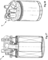
- the filter device 10 can be, for example, an oil filter device for cleaning engine oil of an internal combustion engine of a motor vehicle.
- the filter device 10 can be arranged, for example, in an engine oil circuit of the internal combustion engine.
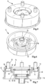
- the filter device 10 includes a connection head 12 in the figure 1 above, to which a treatment element in the form of an exchangeable filter 16 is screwed separably below via a connection adapter 14 according to a first exemplary embodiment.
- the filter device 10 has an imaginary connection axis 18 with respect to which a detachable screw connection between the replaceable filter 16 and the connection adapter 14 is realized.
- connection head 12 can be firmly connected to a component of the internal combustion engine, for example an engine block or a frame of the internal combustion engine.
- the connection head 12 comprises an outlet line 20 for cleaned oil, which opens into a coaxial connection piece 22 on the connection side of the connection head 12 facing the replaceable filter 16 .
- connection piece 22 runs conically and tapers towards the free end of the connection piece 22 which faces the connection adapter 14 .
- the connecting piece 22 is surrounded by a coaxial annular wall 24 in the region of its end axially remote from the replaceable filter 16 .
- An annular inlet space 26 is realized radially between the annular wall 24 and the connecting piece 22 , into which an inlet line 28 of the connection head 12 for engine oil to be cleaned opens.
- connection surface 30 Radially on the outside, the ring wall 24 is surrounded by an annular coaxial connection surface 30 which faces the connection adapter 14 .
- a total of 4 threaded bores 32 are arranged in the connection surface 30 , distributed uniformly around the circumference, the axes of which run parallel to the connection axis 18 .
- the exchangeable filter 16 is a known spin-on filter.
- the replaceable filter 16 includes a filter housing in which a filter element for cleaning the engine oil is arranged.
- a housing cover 34 closes the filter housing and is located on the side facing the connection head 12 axially.
- the housing cover 34 has a coaxial connection opening 36 with an internal thread, which also serves as an outlet for cleaned engine oil.
- the connection opening 36 is connected to an area of the interior of the filter housing on the clean oil side.
- connection opening 36 is surrounded by a plurality of eccentrically arranged inlet openings 38 for engine oil to be cleaned, which lead into a crude oil-side area of the interior of the filter housing.
- a coaxial ring seal 40 connected circumferentially is arranged on the housing cover 34 .
- the ring seal 40 seals against the connection adapter 14 in the axial direction.
- connection adapter 14 is arranged axially between the connection head 12 and the replaceable filter 16 .
- the connection adapter 14 is designed in one piece overall.
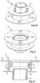
- the connection adapter 14 has an approximately cup-like shape on the outside. It has a connection section 42 for connection to the connection head 12 and a coaxial screw socket section 44 with an external thread for screwing on the internal thread of the connection opening 36 of the replaceable filter 16.
- connection adapter 14 has a coaxial, circumferentially continuous circumferential wall 46 which is adjoined on the bottom side of the cup-shaped connection adapter 14 axially facing the connection head 12 by a circumferentially extending annular coaxial fastening section 48 .
- Four screw holes 50 are arranged in the fastening section 48 , distributed uniformly around the circumference, which are each associated with the threaded holes 32 of the connection head 12 .
- the screw holes 50 are each arranged approximately centrally in the fastening section 48 when viewed in the radial direction.
- a first cylinder section 52 in the form of a hollow cylinder is connected to a radially inner edge of the fastening section 48 and extends coaxially away from the fastening section 48 into the interior of the cup-shaped connection adapter 14 .
- the first cylinder section 52 merges in one piece into a second, coaxial, head-side cylinder section 54, which is also in the form of a hollow cylinder.
- the diameter of the head-side cylinder section 54 is smaller than that of the first cylinder section 52.
- the head-side cylinder section 54 overlaps the first cylinder section 52 on the side facing the connection head 12 axially.
- one end of the annular wall 24 of the connection head 12 is inserted into a groove formed thereby between the radially inner circumferential side of the first cylinder section 52 and the radially outer circumferential side of the head-side cylinder section 54 .
- the head-side cylinder section 54 merges via a radially inwardly extending collar 58 into a third, coaxial, element-side cylinder section 60, also in the form of a hollow cylinder.
- the diameter of the element-side cylinder section 60 is smaller than the diameter of the head-side cylinder section 54.
- a plurality of oil passage holes 62 are distributed circumferentially in the collar 58 .
- An oil-carrying annular space 64 is connected to an oil inlet space 66 with the oil passage holes 62 .
- the annular space 64 is arranged radially between the radially inner peripheral side of the cylinder section 54 on the head side and a radially outer peripheral side of the connecting piece 22 .
- the oil inlet chamber 66 is delimited by the fastening section 48, the cylinder sections 52, 54 and 60, the peripheral wall 46 and, in the assembled state, by the housing cover 34 of the replaceable filter 16.
- a gap between the radially outer peripheral wall of the connecting piece 22 and the ring seal 56 on the crude oil side forms an oil connection between the annular inlet space 26 of the connection head 12 and the annular space 64 in the area of the connection adapter 14.
- the annular space 64, the oil passage holes 62 and the oil inlet space 66 form an oil line for engine oil to be cleaned, which is located radially on the outside of the screw connector section 44, for connecting the annular inlet space 26 on the connection head 12 side to the inlet openings 38 on the replaceable filter 16 side.
- a coaxial, circumferentially coherent ring seal 68 on the pure oil side is arranged on the edge of the element-side cylinder section 60, which faces the connection head 12 axially.
- the ring seal 68 on the clean oil side seals the radially outer peripheral side of the connection piece 22 against the element-side cylinder section 60 and separates the annular space 64 on the crude oil side from the inner spaces of the screw connection piece section 44 and the connection piece 22 on the clean oil side.
- the ring seal 68 is part of an element sealing device.
- the cylinder section 60 on the element side merges via a step which extends radially inwards into the screw socket section 44 with a narrower cross section.
- the free end face of the connecting piece 22 rests against the step at the transition between the cylinder section 60 on the element side and the screw connecting piece section 44 .
- the interior of the screw socket section 44 forms an oil passage duct for connecting the interior of the easy-change filter 16 on the clean oil side to the outlet line 20.
- connection adapter 14 To fix the connection adapter 14 in place, four fastening screws 70 are provided, for example, which lead through the screw holes 50 from the side facing the replaceable filter 16 and are screwed into the threaded holes 32 .
- a ring seal for example in the form of O-ring seals 72 , is arranged between the heads of the fastening screws 70 and the fastening section 48 .
- the O-ring seals 72 each bear in a sealing manner against corresponding annular sealing surfaces 74 surrounding the respective screw holes 50, respectively.
- the O-ring seals 72 seal the oil inlet chamber 66 on the crude oil side in the area of the fastening screws 70 against the environment.
- Each O-ring seal 72 forms a screw hole sealing device with the corresponding sealing surface 74 .
- the free edge of the peripheral wall 46 facing the replaceable filter 16 has a sealing collar 76 which preferably extends radially outward in order to provide a sealing surface that is wider than the thickness of the peripheral wall 46 .
- the sealing collar 76 is in sealing contact with the ring seal 40 of the replaceable filter 16 .
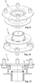
- a filter device 10 with a connection adapter 14 according to a second exemplary embodiment is shown.
- Those elements to those of the first embodiment from the Figures 1 to 9 are similar are provided with the same reference numerals.
- the second exemplary embodiment differs from the first exemplary embodiment in that the screw holes 50 are offset radially inwards from the first cylinder section 52 instead of being arranged centrally in the fastening section 48 .
- a filter device 10 with a connection adapter 14 according to a third exemplary embodiment is shown.
- the third embodiment differs from the first embodiment in that the peripheral wall 46 is offset radially inward so that the bolt holes 50 are located radially outward of the peripheral wall 46 .
- the peripheral wall 46 merges directly into the first cylinder section 52 .
- the peripheral wall 46 is connected with its edge axially facing the replaceable filter 16 to the element-side cylinder section 60 via a ring-disc-shaped connection which has the oil passage holes 62 and the sealing surface 74 .
- the cylinder section 60 on the element side merges directly into the connecting piece 22 with the same diameter.
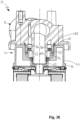
- a filter device 10 is shown with a connection adapter 14 according to a fourth exemplary embodiment, which differs from the embodiment of FIG Figures 1 to 9 by the way in which the connection adapter 14 is fastened to the connection head 12.
- a central thread 480 is provided between the connection head 12 and the connection adapter 14 instead of the screws 70 .
- the central thread 480 is preferably arranged radially outside the seals, in particular outside the head sealing device 56 and the ring seal 68 on the clean oil side, and thus outside the area through which fluids flow or come into contact.
- the first cylinder section 52 has an internal thread and the annular wall 24 has an external thread to form the central thread 480.
- the alternative connection adapter 14 has a coaxial, circumferentially continuous circumferential wall 46, deviating from the embodiment of FIG figure 1 a closed bottom side of the cup-shaped connection adapter 14 axially facing the connection head 12 and a fastening section 48 which adjoins the bottom side and is formed by the central thread 480 .
- the central thread 480 is coaxial with the seals 68, 56.
- the central thread 480 is preferably arranged axially relative to the seals 68, 56 such that they only reach the sealing position when part of the thread path of the internal thread has been overcome during its assembly.
- the first cylinder section 52 having an internal thread as the central thread 480 in each case.
- the central thread is preferably arranged radially outside of the seals 56, 68; in other words, the central thread 480 preferably has a larger diameter than the seals 56, 68 and/or their sealing surfaces.
Landscapes
- Engineering & Computer Science (AREA)
- Chemical & Material Sciences (AREA)
- Mechanical Engineering (AREA)
- General Engineering & Computer Science (AREA)
- Chemical Kinetics & Catalysis (AREA)
- Combustion & Propulsion (AREA)
- Lubrication Details And Ventilation Of Internal Combustion Engines (AREA)
- Quick-Acting Or Multi-Walled Pipe Joints (AREA)
Claims (12)
- Adaptateur de raccordement (14) destiné à raccorder un dispositif de traitement (16) à une tête de raccordement (12) d'une installation de traitement (10) pour des fluides notamment liquides, notamment d'un moteur à combustion interne, notamment d'un véhicule automobile, l'adaptateur de raccordement (14) présentant une section de raccordement (42) destinée à être raccordée à la tête de raccordement (12) et une section de tubulure filetée (44) coaxiale par rapport à un axe de jonction imaginaire (18) pour le vissage du dispositif de traitement (16), la section de tubulure filetée (44) comprenant au moins un canal de passage de fluide pour relier un espace de guidage de fluide du dispositif de traitement (16) à un espace de guidage de fluide (20) de la tête de raccordement (12), la section de raccordement (42), au moins au nombre d'une, présentant au moins deux trous de vis (50) pour des vis (70) ou des boulons filetés ou un filetage central (480) pour le raccordement à un filetage central du côté de la tête de raccordement, caractérisé en ce que le dispositif de traitement présente un filtre interchangeable (16) et l'adaptateur de raccordement (14) présente une collerette d'étanchéité (76) tournée vers le filtre interchangeable (16) à raccorder pour l'application d'un joint annulaire extérieur (40) du filtre interchangeable (16) à raccorder, qui est disposé de préférence sur un bord libre de la paroi circonférentielle (46), la collerette d'étanchéité (76) étant disposée radialement à l'extérieur de la section de raccordement (42).
- Adaptateur de raccordement selon la revendication 1, caractérisé en ce que les trous de vis (50) sont disposés radialement à l'extérieur de la section de tubulure filetée (44) ou d'une projection axiale de la section de tubulure filetée (44) par rapport à l'axe de jonction (18).
- Adaptateur de raccordement selon la revendication 1 ou 2, caractérisé en ce que l'adaptateur de raccordement (14) présente au moins une partie (64, 66) d'au moins une conduite de fluide située radialement à l'extérieur, qui se trouve radialement à l'extérieur de la section de tubulure filetée (44) ou d'une projection axiale de la section de tubulure filetée (44) et qui sert à relier un autre espace de guidage de fluide du dispositif de traitement (16) à un autre espace de guidage de fluide (26) de la tête de raccordement (12).
- Adaptateur de raccordement selon l'une quelconque des revendications précédentes, caractérisé en ce que la section de raccordement (42) présente au moins une section cylindrique (54, 60) coaxiale par rapport à l'axe de jonction (18) pour recevoir une tubulure de raccord (22) de la tête de raccordement (12) coaxial par rapport à l'axe de jonction (18).
- Adaptateur de raccordement selon l'une quelconque des revendications précédentes, caractérisé en ce que l'adaptateur de raccordement (14) présente une paroi circonférentielle(46) qui entoure en sens circonférentiel au moins un espace annulaire (66) conduisant le fluide de l'adaptateur de raccordement (14) par rapport à l'axe de jonction (18).
- Adaptateur de raccordement selon l'une quelconque des revendications précédentes, caractérisé en ce que la collerette d'étanchéité (76) est disposée radialement à l'extérieur des trous de vis (50), au moins au nombre de deux, ou du filetage central (480).
- Adaptateur de raccordement selon la revendication 5 ou 6, caractérisé en ce qu'au moins un trou de vis (50) est disposé par rapport à l'axe de jonction (18) radialement à l'intérieur de la paroi circonférentielle (46) ou d'une projection axiale de la paroi circonférentielle (46) et/ou au moins un trou de vis (50) est disposé par rapport à l'axe de jonction (18) radialement à l'extérieur de la paroi circonférentielle (46) ou d'une projection axiale de la paroi circonférentielle (46).
- Adaptateur de raccordement selon l'une quelconque des revendications précédentes, caractérisé en ce que l'adaptateur de raccordement (14) présente au moins une partie d'un dispositif d'étanchéité d'élément (68) destiné à rendre étanche un raccordement avec le dispositif de traitement (16) et/ou au moins une partie d'un dispositif d'étanchéité de tête (56) pour rendre étanche un raccordement avec la tête de raccordement (12).
- Adaptateur de raccordement selon l'une quelconque des revendications précédentes, caractérisé en ce qu'au moins une partie d'un dispositif d'étanchéité de trou de vis (72, 74) est disposée sur au moins un trou de vis (50).
- Adaptateur de raccordement selon l'une quelconque des revendications précédentes, caractérisé en ce que l'adaptateur de raccordement (14) est conçu d'un seul tenant avec la section de raccordement (42) et la section de tubulure filetée (44).
- Installation comprenant une tête de raccordement (12) d'une installation de traitement (10), notamment de fluides liquides, et au moins un adaptateur de raccordement (14) selon l'une quelconque des revendications précédentes, la section de raccordement (42) de l'adaptateur de raccordement (14), au moins au nombre d'un, étant raccordée à la tête de raccordement (12), et la tête de raccordement (12) présentant un espace de guidage de fluide (20) et le canal de passage de fluide de la section de tubulure filetée (44) étant conçu pour relier un espace de guidage de fluide du dispositif de traitement (16) à l'espace de guidage de fluide (20) de la tête de raccordement (12).
- Installation de traitement (10) comprenant au moins une installation selon la revendication 11 et au moins un dispositif de traitement (16), le dispositif de traitement (16) étant raccordé à la tête de raccordement (12), au moins au nombre d'une, au moyen de l'adaptateur de raccordement (14), au moins au nombre d'un, le canal de passage de fluide, au moins au nombre d'un, de la section de tubulure filetée (44) relie un espace de guidage de fluide du dispositif de traitement (16), au moins au nombre d'un, à l'espace de guidage de fluide (20) de la tête de raccordement (12), et le dispositif de traitement présentant un filtre interchangeable (16).
Applications Claiming Priority (2)
| Application Number | Priority Date | Filing Date | Title |
|---|---|---|---|
| DE102017003368 | 2017-04-06 | ||
| PCT/EP2018/058873 WO2018185292A1 (fr) | 2017-04-06 | 2018-04-06 | Adaptateur de raccordement pour raccorder un dispositif de traitement à une tête de raccordement d'un dispositif de traitement pour en particulier des fluides liquides, tête de raccordement et dispositif de traitement |
Publications (2)
| Publication Number | Publication Date |
|---|---|
| EP3607176A1 EP3607176A1 (fr) | 2020-02-12 |
| EP3607176B1 true EP3607176B1 (fr) | 2023-07-12 |
Family
ID=62002116
Family Applications (1)
| Application Number | Title | Priority Date | Filing Date |
|---|---|---|---|
| EP18718119.3A Active EP3607176B1 (fr) | 2017-04-06 | 2018-04-06 | Adaptateur de connexion pour connecter un dispositif de traitement à une tête de connexion d'un dispositif de traitement, en particulier pour fluides liquides, tête de connexion et dispositif de traitement |
Country Status (7)
| Country | Link |
|---|---|
| US (1) | US11365657B2 (fr) |
| EP (1) | EP3607176B1 (fr) |
| CN (1) | CN110462175B (fr) |
| DE (2) | DE112018001917A5 (fr) |
| ES (1) | ES2952983T3 (fr) |
| PL (1) | PL3607176T3 (fr) |
| WO (1) | WO2018185292A1 (fr) |
Families Citing this family (1)
| Publication number | Priority date | Publication date | Assignee | Title |
|---|---|---|---|---|
| USD958931S1 (en) * | 2020-08-26 | 2022-07-26 | Wuhu TianHao E-commerce CO., LTD. | Oil water separator with replaceable filter |
Family Cites Families (23)
| Publication number | Priority date | Publication date | Assignee | Title |
|---|---|---|---|---|
| US3334754A (en) * | 1964-11-23 | 1967-08-08 | Marvel Eng Co | Filter head structure |
| US4492632A (en) * | 1983-12-16 | 1985-01-08 | Mattson Fred P | Adaptor for external oil filter |
| DE4037628A1 (de) * | 1990-11-27 | 1992-06-04 | Reinhard Weber | Zwischenplatte zwischen spin-on-filter und motorblock |
| US5291969A (en) * | 1992-06-16 | 1994-03-08 | Diederich Paul W Jun | Adapter mechanism for fluid cooling and filtering |
| US5743358A (en) * | 1993-09-22 | 1998-04-28 | K. J. Manufacturing Co. | Filter mounting adapter and fitting mounted to same |
| DE69414814T2 (de) * | 1993-12-13 | 1999-04-15 | Stanadyne Automotive Corp., Windsor, Conn. | Hauptfiltrationsmodul für Brennstoff mit wahlweisen Umstellmöglichkeiten |
| US5484527A (en) * | 1993-12-13 | 1996-01-16 | Stanadyne Automotive Corp. | Module for filter assembly base |
| US5762671A (en) | 1997-02-13 | 1998-06-09 | Farrow; James V. | Multi-size threaded adapter |
| US20010037971A1 (en) * | 1999-05-28 | 2001-11-08 | Gary P. Bergeron | Oil filter adapter |
| US6355169B1 (en) * | 2000-04-24 | 2002-03-12 | Vortex International, Llc | Oil filter adapter ring |
| JP4159284B2 (ja) * | 2001-12-21 | 2008-10-01 | 富士重工業株式会社 | オイルフィルタ装置 |
| US7329337B2 (en) * | 2003-05-22 | 2008-02-12 | Caterpillar Inc. | Universal filter base and engines using same |
| US20070267339A1 (en) * | 2004-04-21 | 2007-11-22 | Munn Myron L | Oil filter adapter |
| DE102004059061B4 (de) | 2004-12-07 | 2021-12-02 | Mann+Hummel Gmbh | Flüssigkeitsfilter und Verwendung desselben |
| CN1840871A (zh) * | 2005-03-11 | 2006-10-04 | 卡特彼勒公司 | 可安装在远处的过滤器组件 |
| US20120285876A1 (en) * | 2011-05-10 | 2012-11-15 | Parker-Hannifin Corporation | Filter manifold mount |
| FR2976188A1 (fr) * | 2011-06-09 | 2012-12-14 | Filtrauto | Filtre a liquide et sous-ensemble de moteur formant support de montage pour une cartouche filtrante |
| CA2797323C (fr) | 2012-11-29 | 2019-04-23 | Filterspec Inc. | Dispositif de cartouche de filtre |
| FI124391B (en) * | 2013-01-10 | 2014-08-15 | Outotec Finland Oy | Filter plate connector |
| GB201315647D0 (en) | 2013-09-03 | 2013-10-16 | Parker Hannifin Mfg Ltd | A filter element and cover assembly therefor |
| US20150298033A1 (en) * | 2014-04-21 | 2015-10-22 | Hatton Marine and Industrial Repair, Inc. | Fuel filter adapter plate |
| BR102014020222A2 (pt) | 2014-08-14 | 2015-06-09 | Devocir Antônio Lira | Conector universal para filtro de combustível para máquinas agrícolas |
| CN205689262U (zh) * | 2016-06-03 | 2016-11-16 | 力帆实业(集团)股份有限公司 | 摩托车发动机机油滤清器 |
-
2018
- 2018-04-06 CN CN201880021562.0A patent/CN110462175B/zh active Active
- 2018-04-06 ES ES18718119T patent/ES2952983T3/es active Active
- 2018-04-06 DE DE112018001917.9T patent/DE112018001917A5/de not_active Withdrawn
- 2018-04-06 EP EP18718119.3A patent/EP3607176B1/fr active Active
- 2018-04-06 DE DE102018002909.4A patent/DE102018002909A1/de not_active Withdrawn
- 2018-04-06 WO PCT/EP2018/058873 patent/WO2018185292A1/fr not_active Ceased
- 2018-04-06 PL PL18718119.3T patent/PL3607176T3/pl unknown
-
2019
- 2019-10-04 US US16/593,805 patent/US11365657B2/en active Active
Also Published As
| Publication number | Publication date |
|---|---|
| DE112018001917A5 (de) | 2019-12-19 |
| WO2018185292A1 (fr) | 2018-10-11 |
| CN110462175A (zh) | 2019-11-15 |
| US11365657B2 (en) | 2022-06-21 |
| EP3607176A1 (fr) | 2020-02-12 |
| US20200102921A1 (en) | 2020-04-02 |
| DE102018002909A1 (de) | 2018-10-11 |
| CN110462175B (zh) | 2022-07-12 |
| PL3607176T3 (pl) | 2023-11-27 |
| ES2952983T3 (es) | 2023-11-07 |
Similar Documents
| Publication | Publication Date | Title |
|---|---|---|
| EP2982427B1 (fr) | Boitier et dispositif destine a separer un fluide | |
| EP2459295B1 (fr) | Filtre | |
| EP3228374B1 (fr) | Filtre amovible d'un dispositif de traitement destiné à traiter en particulier des fluides liquides et dispositif de traitement | |
| EP3096859B1 (fr) | Élément de filtration | |
| EP3408009B1 (fr) | Boîtier, élément d'étanchéité pour orifice de sortie de fluide, couvercle de boîtier et élément de liaison d'un dispositif conçu pour séparer au moins un fluide d'un gaz et dispositif pour séparer un fluide | |
| EP3019265B1 (fr) | Filtre à visser pour dispositif de filtration de fluide et dispositif de filtration | |
| DE102012209242A1 (de) | Filtereinrichtung | |
| EP2514958B1 (fr) | Filtre de carburant pour un moteur à combustion interne | |
| DE102013019807A1 (de) | Filtervorrichtung | |
| DE102015008328B4 (de) | Filteranschlusseinrichtung und Filtereinrichtung | |
| EP3727643B1 (fr) | Élément filtrant d'un filtre à liquide et filtre | |
| DE102016010523B4 (de) | Filtergehäuse eines austauschbaren Filters, Filter und Filtervorrichtung | |
| EP3793707B1 (fr) | Filtre avec un boîtier et un couvercle intermédiaire | |
| DE102016008732A1 (de) | Fluidgehäuse eines Fluidbehandlungssystem und Fluidbehandlungssystem | |
| WO2018185292A1 (fr) | Adaptateur de raccordement pour raccorder un dispositif de traitement à une tête de raccordement d'un dispositif de traitement pour en particulier des fluides liquides, tête de raccordement et dispositif de traitement | |
| WO2022053384A1 (fr) | Élément filtrant, dispositif de filtrage, procédé d'assemblage et d'agencement | |
| EP3727642B1 (fr) | Filtre avec un élément de fermeture d'écoulement | |
| DE102015008694A1 (de) | Hohlfilterelement eines Flüssigkeitsfilters, Flüssigkeitsfilter, Filtersystem und Adapterelement eines Hohlfilterelements | |
| EP2114546B1 (fr) | Élément filtrant destiné à la purification de liquides | |
| EP4028143B1 (fr) | Élément d'épuration de fluide d'un système d'épuration de fluide conçu pour épurer un fluide liquide, système d'épuration de fluide et élément d'étanchéité d'un élément d'épuration de fluide | |
| DE102014005348B4 (de) | Filterelement eines Filters und Filter | |
| DE102017004558B4 (de) | Gehäusemodul eines Fluidbehandlungsmoduls und Fluidbehandlungsmodul | |
| EP4620552A1 (fr) | Élément filtrant, élément filtrant échangeur d'ions et système de filtration | |
| WO2017153210A1 (fr) | Dispositif de raccordement de filtre d'un dispositif filtrant destiné au raccordement d'un filtre interchangeable et dispositif filtrant | |
| WO2025011836A1 (fr) | Élément filtrant, élément de fermeture de drain et système de filtration |
Legal Events
| Date | Code | Title | Description |
|---|---|---|---|
| STAA | Information on the status of an ep patent application or granted ep patent |
Free format text: STATUS: UNKNOWN |
|
| STAA | Information on the status of an ep patent application or granted ep patent |
Free format text: STATUS: THE INTERNATIONAL PUBLICATION HAS BEEN MADE |
|
| PUAI | Public reference made under article 153(3) epc to a published international application that has entered the european phase |
Free format text: ORIGINAL CODE: 0009012 |
|
| STAA | Information on the status of an ep patent application or granted ep patent |
Free format text: STATUS: REQUEST FOR EXAMINATION WAS MADE |
|
| 17P | Request for examination filed |
Effective date: 20190926 |
|
| AK | Designated contracting states |
Kind code of ref document: A1 Designated state(s): AL AT BE BG CH CY CZ DE DK EE ES FI FR GB GR HR HU IE IS IT LI LT LU LV MC MK MT NL NO PL PT RO RS SE SI SK SM TR |
|
| AX | Request for extension of the european patent |
Extension state: BA ME |
|
| DAV | Request for validation of the european patent (deleted) | ||
| DAX | Request for extension of the european patent (deleted) | ||
| RAP3 | Party data changed (applicant data changed or rights of an application transferred) |
Owner name: MANN+HUMMEL GMBH |
|
| STAA | Information on the status of an ep patent application or granted ep patent |
Free format text: STATUS: EXAMINATION IS IN PROGRESS |
|
| 17Q | First examination report despatched |
Effective date: 20210601 |
|
| GRAP | Despatch of communication of intention to grant a patent |
Free format text: ORIGINAL CODE: EPIDOSNIGR1 |
|
| STAA | Information on the status of an ep patent application or granted ep patent |
Free format text: STATUS: GRANT OF PATENT IS INTENDED |
|
| INTG | Intention to grant announced |
Effective date: 20230208 |
|
| GRAS | Grant fee paid |
Free format text: ORIGINAL CODE: EPIDOSNIGR3 |
|
| GRAA | (expected) grant |
Free format text: ORIGINAL CODE: 0009210 |
|
| STAA | Information on the status of an ep patent application or granted ep patent |
Free format text: STATUS: THE PATENT HAS BEEN GRANTED |
|
| AK | Designated contracting states |
Kind code of ref document: B1 Designated state(s): AL AT BE BG CH CY CZ DE DK EE ES FI FR GB GR HR HU IE IS IT LI LT LU LV MC MK MT NL NO PL PT RO RS SE SI SK SM TR |
|
| REG | Reference to a national code |
Ref country code: CH Ref legal event code: EP |
|
| REG | Reference to a national code |
Ref country code: DE Ref legal event code: R096 Ref document number: 502018012673 Country of ref document: DE |
|
| REG | Reference to a national code |
Ref country code: IE Ref legal event code: FG4D Free format text: LANGUAGE OF EP DOCUMENT: GERMAN |
|
| REG | Reference to a national code |
Ref country code: LT Ref legal event code: MG9D |
|
| REG | Reference to a national code |
Ref country code: NL Ref legal event code: MP Effective date: 20230712 |
|
| PG25 | Lapsed in a contracting state [announced via postgrant information from national office to epo] |
Ref country code: NL Free format text: LAPSE BECAUSE OF FAILURE TO SUBMIT A TRANSLATION OF THE DESCRIPTION OR TO PAY THE FEE WITHIN THE PRESCRIBED TIME-LIMIT Effective date: 20230712 |
|
| PG25 | Lapsed in a contracting state [announced via postgrant information from national office to epo] |
Ref country code: GR Free format text: LAPSE BECAUSE OF FAILURE TO SUBMIT A TRANSLATION OF THE DESCRIPTION OR TO PAY THE FEE WITHIN THE PRESCRIBED TIME-LIMIT Effective date: 20231013 |
|
| PG25 | Lapsed in a contracting state [announced via postgrant information from national office to epo] |
Ref country code: IS Free format text: LAPSE BECAUSE OF FAILURE TO SUBMIT A TRANSLATION OF THE DESCRIPTION OR TO PAY THE FEE WITHIN THE PRESCRIBED TIME-LIMIT Effective date: 20231112 |
|
| PG25 | Lapsed in a contracting state [announced via postgrant information from national office to epo] |
Ref country code: SE Free format text: LAPSE BECAUSE OF FAILURE TO SUBMIT A TRANSLATION OF THE DESCRIPTION OR TO PAY THE FEE WITHIN THE PRESCRIBED TIME-LIMIT Effective date: 20230712 Ref country code: RS Free format text: LAPSE BECAUSE OF FAILURE TO SUBMIT A TRANSLATION OF THE DESCRIPTION OR TO PAY THE FEE WITHIN THE PRESCRIBED TIME-LIMIT Effective date: 20230712 Ref country code: PT Free format text: LAPSE BECAUSE OF FAILURE TO SUBMIT A TRANSLATION OF THE DESCRIPTION OR TO PAY THE FEE WITHIN THE PRESCRIBED TIME-LIMIT Effective date: 20231113 Ref country code: NO Free format text: LAPSE BECAUSE OF FAILURE TO SUBMIT A TRANSLATION OF THE DESCRIPTION OR TO PAY THE FEE WITHIN THE PRESCRIBED TIME-LIMIT Effective date: 20231012 Ref country code: LV Free format text: LAPSE BECAUSE OF FAILURE TO SUBMIT A TRANSLATION OF THE DESCRIPTION OR TO PAY THE FEE WITHIN THE PRESCRIBED TIME-LIMIT Effective date: 20230712 Ref country code: LT Free format text: LAPSE BECAUSE OF FAILURE TO SUBMIT A TRANSLATION OF THE DESCRIPTION OR TO PAY THE FEE WITHIN THE PRESCRIBED TIME-LIMIT Effective date: 20230712 Ref country code: IS Free format text: LAPSE BECAUSE OF FAILURE TO SUBMIT A TRANSLATION OF THE DESCRIPTION OR TO PAY THE FEE WITHIN THE PRESCRIBED TIME-LIMIT Effective date: 20231112 Ref country code: HR Free format text: LAPSE BECAUSE OF FAILURE TO SUBMIT A TRANSLATION OF THE DESCRIPTION OR TO PAY THE FEE WITHIN THE PRESCRIBED TIME-LIMIT Effective date: 20230712 Ref country code: GR Free format text: LAPSE BECAUSE OF FAILURE TO SUBMIT A TRANSLATION OF THE DESCRIPTION OR TO PAY THE FEE WITHIN THE PRESCRIBED TIME-LIMIT Effective date: 20231013 Ref country code: FI Free format text: LAPSE BECAUSE OF FAILURE TO SUBMIT A TRANSLATION OF THE DESCRIPTION OR TO PAY THE FEE WITHIN THE PRESCRIBED TIME-LIMIT Effective date: 20230712 |
|
| REG | Reference to a national code |
Ref country code: DE Ref legal event code: R097 Ref document number: 502018012673 Country of ref document: DE |
|
| PG25 | Lapsed in a contracting state [announced via postgrant information from national office to epo] |
Ref country code: SM Free format text: LAPSE BECAUSE OF FAILURE TO SUBMIT A TRANSLATION OF THE DESCRIPTION OR TO PAY THE FEE WITHIN THE PRESCRIBED TIME-LIMIT Effective date: 20230712 Ref country code: RO Free format text: LAPSE BECAUSE OF FAILURE TO SUBMIT A TRANSLATION OF THE DESCRIPTION OR TO PAY THE FEE WITHIN THE PRESCRIBED TIME-LIMIT Effective date: 20230712 Ref country code: EE Free format text: LAPSE BECAUSE OF FAILURE TO SUBMIT A TRANSLATION OF THE DESCRIPTION OR TO PAY THE FEE WITHIN THE PRESCRIBED TIME-LIMIT Effective date: 20230712 Ref country code: DK Free format text: LAPSE BECAUSE OF FAILURE TO SUBMIT A TRANSLATION OF THE DESCRIPTION OR TO PAY THE FEE WITHIN THE PRESCRIBED TIME-LIMIT Effective date: 20230712 Ref country code: CZ Free format text: LAPSE BECAUSE OF FAILURE TO SUBMIT A TRANSLATION OF THE DESCRIPTION OR TO PAY THE FEE WITHIN THE PRESCRIBED TIME-LIMIT Effective date: 20230712 Ref country code: SK Free format text: LAPSE BECAUSE OF FAILURE TO SUBMIT A TRANSLATION OF THE DESCRIPTION OR TO PAY THE FEE WITHIN THE PRESCRIBED TIME-LIMIT Effective date: 20230712 |
|
| P01 | Opt-out of the competence of the unified patent court (upc) registered |
Effective date: 20240321 |
|
| PLBE | No opposition filed within time limit |
Free format text: ORIGINAL CODE: 0009261 |
|
| STAA | Information on the status of an ep patent application or granted ep patent |
Free format text: STATUS: NO OPPOSITION FILED WITHIN TIME LIMIT |
|
| 26N | No opposition filed |
Effective date: 20240415 |
|
| PG25 | Lapsed in a contracting state [announced via postgrant information from national office to epo] |
Ref country code: SI Free format text: LAPSE BECAUSE OF FAILURE TO SUBMIT A TRANSLATION OF THE DESCRIPTION OR TO PAY THE FEE WITHIN THE PRESCRIBED TIME-LIMIT Effective date: 20230712 |
|
| PG25 | Lapsed in a contracting state [announced via postgrant information from national office to epo] |
Ref country code: MC Free format text: LAPSE BECAUSE OF FAILURE TO SUBMIT A TRANSLATION OF THE DESCRIPTION OR TO PAY THE FEE WITHIN THE PRESCRIBED TIME-LIMIT Effective date: 20230712 |
|
| PG25 | Lapsed in a contracting state [announced via postgrant information from national office to epo] |
Ref country code: MC Free format text: LAPSE BECAUSE OF FAILURE TO SUBMIT A TRANSLATION OF THE DESCRIPTION OR TO PAY THE FEE WITHIN THE PRESCRIBED TIME-LIMIT Effective date: 20230712 |
|
| REG | Reference to a national code |
Ref country code: CH Ref legal event code: PL |
|
| PG25 | Lapsed in a contracting state [announced via postgrant information from national office to epo] |
Ref country code: LU Free format text: LAPSE BECAUSE OF NON-PAYMENT OF DUE FEES Effective date: 20240406 |
|
| REG | Reference to a national code |
Ref country code: BE Ref legal event code: MM Effective date: 20240430 |
|
| PG25 | Lapsed in a contracting state [announced via postgrant information from national office to epo] |
Ref country code: LU Free format text: LAPSE BECAUSE OF NON-PAYMENT OF DUE FEES Effective date: 20240406 |
|
| PG25 | Lapsed in a contracting state [announced via postgrant information from national office to epo] |
Ref country code: BE Free format text: LAPSE BECAUSE OF NON-PAYMENT OF DUE FEES Effective date: 20240430 |
|
| PG25 | Lapsed in a contracting state [announced via postgrant information from national office to epo] |
Ref country code: BE Free format text: LAPSE BECAUSE OF NON-PAYMENT OF DUE FEES Effective date: 20240430 Ref country code: CH Free format text: LAPSE BECAUSE OF NON-PAYMENT OF DUE FEES Effective date: 20240430 |
|
| PG25 | Lapsed in a contracting state [announced via postgrant information from national office to epo] |
Ref country code: IE Free format text: LAPSE BECAUSE OF NON-PAYMENT OF DUE FEES Effective date: 20240406 |
|
| REG | Reference to a national code |
Ref country code: AT Ref legal event code: MM01 Ref document number: 1587393 Country of ref document: AT Kind code of ref document: T Effective date: 20240406 |
|
| PGFP | Annual fee paid to national office [announced via postgrant information from national office to epo] |
Ref country code: DE Payment date: 20250422 Year of fee payment: 8 |
|
| PGFP | Annual fee paid to national office [announced via postgrant information from national office to epo] |
Ref country code: GB Payment date: 20250423 Year of fee payment: 8 Ref country code: ES Payment date: 20250530 Year of fee payment: 8 |
|
| PGFP | Annual fee paid to national office [announced via postgrant information from national office to epo] |
Ref country code: IT Payment date: 20250424 Year of fee payment: 8 |
|
| PGFP | Annual fee paid to national office [announced via postgrant information from national office to epo] |
Ref country code: FR Payment date: 20250425 Year of fee payment: 8 |
|
| PGFP | Annual fee paid to national office [announced via postgrant information from national office to epo] |
Ref country code: BG Payment date: 20250424 Year of fee payment: 8 |
|
| PG25 | Lapsed in a contracting state [announced via postgrant information from national office to epo] |
Ref country code: AT Free format text: LAPSE BECAUSE OF NON-PAYMENT OF DUE FEES Effective date: 20240406 |
|
| PGFP | Annual fee paid to national office [announced via postgrant information from national office to epo] |
Ref country code: TR Payment date: 20250402 Year of fee payment: 8 |
|
| PG25 | Lapsed in a contracting state [announced via postgrant information from national office to epo] |
Ref country code: CY Free format text: LAPSE BECAUSE OF FAILURE TO SUBMIT A TRANSLATION OF THE DESCRIPTION OR TO PAY THE FEE WITHIN THE PRESCRIBED TIME-LIMIT; INVALID AB INITIO Effective date: 20180406 |
|
| PG25 | Lapsed in a contracting state [announced via postgrant information from national office to epo] |
Ref country code: HU Free format text: LAPSE BECAUSE OF FAILURE TO SUBMIT A TRANSLATION OF THE DESCRIPTION OR TO PAY THE FEE WITHIN THE PRESCRIBED TIME-LIMIT; INVALID AB INITIO Effective date: 20180406 |
|
| PGFP | Annual fee paid to national office [announced via postgrant information from national office to epo] |
Ref country code: PL Payment date: 20260326 Year of fee payment: 9 |