EP3607207B1 - Inserts résistant à l'abrasion dans des étages de pompe de puits centrifuge - Google Patents
Inserts résistant à l'abrasion dans des étages de pompe de puits centrifuge Download PDFInfo
- Publication number
- EP3607207B1 EP3607207B1 EP18781143.5A EP18781143A EP3607207B1 EP 3607207 B1 EP3607207 B1 EP 3607207B1 EP 18781143 A EP18781143 A EP 18781143A EP 3607207 B1 EP3607207 B1 EP 3607207B1
- Authority
- EP
- European Patent Office
- Prior art keywords
- inserts
- sleeve
- component
- diffuser
- thrust bearing
- Prior art date
- Legal status (The legal status is an assumption and is not a legal conclusion. Google has not performed a legal analysis and makes no representation as to the accuracy of the status listed.)
- Active
Links
Images


Classifications
-
- F—MECHANICAL ENGINEERING; LIGHTING; HEATING; WEAPONS; BLASTING
- F04—POSITIVE - DISPLACEMENT MACHINES FOR LIQUIDS; PUMPS FOR LIQUIDS OR ELASTIC FLUIDS
- F04D—NON-POSITIVE-DISPLACEMENT PUMPS
- F04D1/00—Radial-flow pumps, e.g. centrifugal pumps; Helico-centrifugal pumps
- F04D1/06—Multi-stage pumps
- F04D1/063—Multi-stage pumps of the vertically split casing type
-
- F—MECHANICAL ENGINEERING; LIGHTING; HEATING; WEAPONS; BLASTING
- F04—POSITIVE - DISPLACEMENT MACHINES FOR LIQUIDS; PUMPS FOR LIQUIDS OR ELASTIC FLUIDS
- F04D—NON-POSITIVE-DISPLACEMENT PUMPS
- F04D13/00—Pumping installations or systems
- F04D13/02—Units comprising pumps and their driving means
- F04D13/06—Units comprising pumps and their driving means the pump being electrically driven
- F04D13/08—Units comprising pumps and their driving means the pump being electrically driven for submerged use
- F04D13/10—Units comprising pumps and their driving means the pump being electrically driven for submerged use adapted for use in mining bore holes
-
- F—MECHANICAL ENGINEERING; LIGHTING; HEATING; WEAPONS; BLASTING
- F04—POSITIVE - DISPLACEMENT MACHINES FOR LIQUIDS; PUMPS FOR LIQUIDS OR ELASTIC FLUIDS
- F04D—NON-POSITIVE-DISPLACEMENT PUMPS
- F04D29/00—Details, component parts, or accessories
- F04D29/02—Selection of particular materials
- F04D29/026—Selection of particular materials especially adapted for liquid pumps
-
- F—MECHANICAL ENGINEERING; LIGHTING; HEATING; WEAPONS; BLASTING
- F04—POSITIVE - DISPLACEMENT MACHINES FOR LIQUIDS; PUMPS FOR LIQUIDS OR ELASTIC FLUIDS
- F04D—NON-POSITIVE-DISPLACEMENT PUMPS
- F04D29/00—Details, component parts, or accessories
- F04D29/04—Shafts or bearings, or assemblies thereof
- F04D29/041—Axial thrust balancing
- F04D29/0413—Axial thrust balancing hydrostatic; hydrodynamic thrust bearings
-
- F—MECHANICAL ENGINEERING; LIGHTING; HEATING; WEAPONS; BLASTING
- F04—POSITIVE - DISPLACEMENT MACHINES FOR LIQUIDS; PUMPS FOR LIQUIDS OR ELASTIC FLUIDS
- F04D—NON-POSITIVE-DISPLACEMENT PUMPS
- F04D29/00—Details, component parts, or accessories
- F04D29/04—Shafts or bearings, or assemblies thereof
- F04D29/046—Bearings
- F04D29/047—Bearings hydrostatic; hydrodynamic
- F04D29/0473—Bearings hydrostatic; hydrodynamic for radial pumps
-
- F—MECHANICAL ENGINEERING; LIGHTING; HEATING; WEAPONS; BLASTING
- F04—POSITIVE - DISPLACEMENT MACHINES FOR LIQUIDS; PUMPS FOR LIQUIDS OR ELASTIC FLUIDS
- F04D—NON-POSITIVE-DISPLACEMENT PUMPS
- F04D29/00—Details, component parts, or accessories
- F04D29/70—Suction grids; Strainers; Dust separation; Cleaning
- F04D29/708—Suction grids; Strainers; Dust separation; Cleaning specially for liquid pumps
-
- F—MECHANICAL ENGINEERING; LIGHTING; HEATING; WEAPONS; BLASTING
- F05—INDEXING SCHEMES RELATING TO ENGINES OR PUMPS IN VARIOUS SUBCLASSES OF CLASSES F01-F04
- F05D—INDEXING SCHEME FOR ASPECTS RELATING TO NON-POSITIVE-DISPLACEMENT MACHINES OR ENGINES, GAS-TURBINES OR JET-PROPULSION PLANTS
- F05D2300/00—Materials; Properties thereof
- F05D2300/60—Properties or characteristics given to material by treatment or manufacturing
- F05D2300/603—Composites; e.g. fibre-reinforced
Definitions
- the present disclosure relates to centrifugal pumps systems for well bore fluids. More specifically, the present disclosure relates to pump stages having sleeves with abrasion resistant inserts.
- US 4 678 399 A discloses a centrifugal submersible pump.
- US 4 560 014 A discloses a thrust bearing assembly for a downhole drill motor.
- a typical well pump is a centrifugal type, having many stages, each stages having an impeller and a diffuser.
- the impellers and diffusers are usually castings formed of a nickel-iron alloy.
- the wear due to sand particles includes erosive wear, which usually happens in the flow paths of the impellers and diffusers.
- the wear also includes abrasive wear at the rotational interfaces that perform sealing functions for the well fluid flowing upward through the stages.
- One rotational interface occurs at the impeller skirt and another at the impeller balance ring.
- Abrasive wear is usually worse than erosive wear and results in increased recirculation through the stages. Recirculation due to abrasive wear degrades the pump performance. Also abrasive wear develops more quickly at higher rotational speeds.
- Harder metal abrasion resistant components such as those formed of tungsten carbide, have been incorporated in pump stages to reduce abrasive wear. A variety of different configurations for abrasion resistant components have been proposed and used.
- a well pump assembly has a plurality of modules including a pump and a motor.
- the pump has first and second components that rotate against each other.
- a plurality of inserts are imbedded in a body of the first component, each of the inserts having a face that is flush with a wear surface of the body of the first component.
- the inserts are formed of a harder material than the body of the first component.
- the second component has a body of a harder material than the body of the first component.
- the body of the first component is formed of a nickel iron alloy material.
- the inserts are formed of tungsten carbide.
- the body of the second component is also formed of tungsten carbide.
- the first component of the pump comprises an impeller, and the second component comprises a diffuser.
- the body of the first component comprises a sleeve bonded to a cylindrical wall of the impeller.
- the body of the second component comprises a solid ring bonded to a cylindrical wall of the diffuser against which the faces of the inserts slide.
- each of the inserts may be embedded within a hole in the body of the first component that has a blind end.
- each of the inserts has an insert axis that is normal to the face of each of the inserts.
- each of the inserts has a cylindrical surface extending around the insert axis.
- each of the inserts has a polygonal surface extending around the insert axis.
- the body of the first component comprises a cylindrical wall coaxial with a longitudinal axis and having inner and outer diameter surfaces.
- the wear surface is defined by one of the inner and outer diameter surfaces.
- Each of the inserts is embedded in the cylindrical wall and has an insert axis located on a radial line of the longitudinal axis. The face of each of the inserts is flush with one of the inner and outer diameter surfaces of the cylindrical wall.
- the inserts are located in upper, lower and intermediate adjacent circumferential rows that circumscribe the cylindrical wall perpendicular to the longitudinal axis.
- the insert axes in the intermediate circumferential row are rotationally staggered with the insert axes of the inserts in the upper and lower rows relative to the longitudinal axis.
- the first component may comprise an outward-facing cylindrical wall
- the body may comprise a sleeve bonded to the outward-facing cylindrical wall of the first component, the sleeve having an outer diameter surface that defines the wear surface.
- the inserts may be located in blind holes that open to the outer diameter surface of the sleeve. The faces of the inserts are flush with the outer diameter surface of the sleeve.
- the body of the first component may comprise a tubular down thrust bearing, the down thrust bearing having an outer diameter surface that defines a part of the wear surface.
- the down thrust bearing has a downward facing surface that defines another part of the wear surface.
- a first portion of the inserts are located in blind holes that are radial relative to a longitudinal axis of the down thrust bearing and open to the outer diameter surface of the down thrust bearing. The faces of the first portion of the inserts are flush with the outer diameter surface of the down thrust bearing.
- a second portion of the inserts are located in holes in the downward facing surface of the down thrust bearing. The faces of the second portion of the inserts are flush with the downward surface of the down thrust bearing.
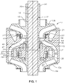
- a centrifugal pump stage 11 includes a lower or upstream impeller 13a having a hub 15 with a bore 17.
- a drive shaft 19 having a longitudinal or shaft axis 20 extends through bore 17.
- a key (not shown) engages axially extending grooves in bore 17 and on the outer diameter of shaft 19 to cause lower impeller 13a to rotate with shaft 19.
- the terms "upper”, “lower” and the like are used only for convenience as the pump containing pump stage 11 may be operated in inclined and horizontal portions of a well.
- Pump stage 11 has a non rotating diffuser 21.
- Diffuser 21 is in a stack of a large number of diffusers (not shown) that are secured within a cylindrical housing (not shown) of a pump.
- Fig. 1 shows lower impeller 13a on the lower side of diffuser 21, and an upper impeller 13b on the upper side of diffuser 21.
- Upper impeller 13b is part of the next upward stage from pump stage 11.
- Shaft 19 extends through a central bore 23 in diffuser 21.
- the upper portion of hub 15 of lower impeller 13a extends into diffuser central bore 23.
- the upper portion of impeller hub 15 of upper impeller 13b extends into the diffuser central bore 23 of the next upward diffuser 21 (not shown).
- Diffuser 21 has a plurality of diffuser passages 25 that extend radially inward and upward from an intake area on the lower side to a discharge area on the upper side.
- Each impeller 13a, 13b has a plurality of impeller passages 27 that extend radially outward and upward from an intake area on the lower side to a discharge at the periphery on the upper side.
- Well fluid discharged from impeller passages 27 of lower impeller 13a flows into diffuser passages 25.
- Well fluid discharged from diffuser passages 25 flows into impeller passages 27 of upper impeller 13b.
- Each impeller 13a, 13b has a cylindrical balance ring 29 integrally formed on its upper side that is concentric with longitudinal axis 20.
- Diffuser 21 has on its lower side an annular downward facing cavity 30 with an inward facing cylindrical wall 31 on an outer diameter of cavity 30.
- Balance ring 29 of lower impeller 13a extends into diffuser cavity 30 and is closely received by cavity inward facing wall 31, defining a sliding rotational interface.
- An abrasion resistant (hereinafter referred to as AR) balance ring sleeve 33 mounts to the outer diameter side of balance ring 29 for rotation therewith.
- AR balance ring sleeve 33 may be mounted or bonded to balance ring 29 in various manners, such as by a shrink-fit, by an adhesive, or by brazing.
- An AR diffuser cavity ring or sleeve 35 may be fixed to diffuser cavity inward facing wall 31.
- AR diffuser cavity sleeve 35 may be secured to cavity inward facing wall 31 in various manners, such as by an adhesive or brazing.
- AR balance ring sleeve 33 is in in rotational sliding engagement with AR diffuser cavity sleeve 35. The sliding engagement stabilizes impeller 13a and also serves to reduce leakage of well fluid from diffuser cavity 30 downward through the interface between balance ring 29 and cavity inward facing wall 31.
- Each impeller 13a, 13b has a cylindrical skirt 37 on its lower side. Skirt 37 of upper impeller 13b is closely received within a cylindrical receptacle 39 on an upper side of diffuser 21. Skirt 37 of lower impeller 13a is closely received with the cylindrical receptacle 39 of the next lower diffuser 21 (not shown).
- An AR skirt ring or sleeve 41 mounts to the outward facing cylindrical wall of each skirt 37 for rotation with impellers 13b, 13a.
- An AR receptacle ring or sleeve 43 may be fixed to the inward facing wall of diffuser receptacle 39. AR skirt sleeve 41 is in rotating sliding engagement with AR receptacle sleeve 43 and also serves to reduce leakage of well fluid through the interface between skirt 37 and diffuser receptacle 39.
- pump stage 11 has an AR down thrust bearing 45 with an inner diameter 47 that closely receives shaft 19.
- AR down thrust bearing 45 is a tubular member, and in this example, it has an external flange 49 on its upper end.
- AR down thrust bearing 45 rotates with shaft 19 and can slide axially a limited extent relative to shaft 19.
- AR down thrust bearing 45 has an outer diameter surface that is in close, sliding reception with the inner diameter of a non-rotating AR bushing 51.
- AR bushing 51 is fixed within a counterbore in diffuser 21 and normally formed of a harder material than diffuser 21.
- a lower spacer ring 53 may be located between the lower end of impeller hub 15 of upper impeller 13b and AR down thrust bearing 45 for transferring down thrust from upper impeller 13b to AR down thrust bearing 45, bushing 51 and diffuser 21.
- Flange 49 transfers the down thrust to the upper end of bushing 51 and is integrally formed with the cylindrical portion of down thrust bearing 45.
- AR down thrust bearings 45 and AR bushings 51 may not be needed in every stage 11.
- an upper spacer tube or ring 55 is shown on the upper end of the hub 15 of upper impeller 13b for receiving down thrust from impellers located above.
- Pump stage 11 may have an impeller down thrust washer 57 on a lower end of upper impeller 13b for engaging an upper side of diffuser 21.
- An up thrust washer 59 may be located on a lower side of diffuser 21 for transferring up thrust from lower impeller 13a to diffuser 21.
- AR balance ring sleeve 33 has an array of hard, wear resistant inserts 61 mounted in the side wall of a cylindrical body 63.
- Inserts 61 are of a material much harder than body 63.
- inserts 61 may be formed of tungsten carbide, and body 63 may be formed of a metal similar or identical to the metal of impellers 13a. 13b ( Fig. 1 ).
- One suitable material is an iron nickel alloy referred to as Ni-Resist.
- Impellers 13a, 13b are conventionally a casting of a Ni-Resist material.
- Each insert 61 in this example is a generally cylindrical, short pin or rod with an insert axis 65 that will be located on a radial line of shaft axis 20 when AR balance ring sleeve 33 is installed.
- Each insert 61 shown in Fig. 2 has a cylindrical exterior 67 concentric with insert axis 65 and secured in a hole in body 63.
- Each insert 61 has a face 68 that is initially flush with the cylindrical exterior of body 63. Face 68 may be flat or slightly curved to match the cylindrical exterior of body 63.
- the radial thickness of body 63 between its inner and outer diameters may be slightly greater than the radial length of each insert 61.
- the inner ends of inserts 61 opposite faces 68 need not extend to the inner diameter of body 63.
- blind holes are drilled in body 63 for inserts 61, then inserts 61 are inserted in the holes.
- the inserts 61 may be secured by an interference fit, adhesive or brazing.
- inserts 61 are formed in a mesh that fixes the inserts in the cylindrical pattern shown in Fig. 2 .
- Three-dimensional printing or fabrication techniques may be used to form the mesh of inserts 61. Thin webs join inserts 61 to each other while in the mesh. Material used to form body 63 will be heated to a molten state; the molten metal of body 63 will be injected through and around the mesh while within a mold, casting the inserts 61 in place.
- the pattern or arrangement of inserts 61 in body 63 may vary.
- circumferential rows of inserts 61 extend around body 63 perpendicular to shaft axis 20.
- the inserts 61 in each circumferential row are rotationally offset from those in adjacent circumferential rows.
- the insert axis 65 of an insert 61 in the intermediate row is rotationally offset equally between the axes 65 of the closest inserts 61 in the upper and lower rows.
- the axes 65 of inserts 61 in the upper row and lower row are aligned axially with each other.
- a line perpendicular to shaft axis 20 and extending from insert axis 65 of one insert 61 in the upper row will pass through insert axis 65 of one insert 61 in the lower row. That line would not pass through the insert axis 65 of any insert 61 in the intermediate row.
- the axes 65 of inserts 61 in the intermediate row are circumferentially spaced or rotationally staggered from the axes 65 in the middle and upper rows.
- AR skirt sleeve 41 may be identical to AR balance ring sleeve 33, other than dimensions, also having abrasion resistant inserts installed in a softer metal body.
- AR diffuser cavity sleeve 35 and AR diffuser receptacle sleeve 43 may be formed of solid tungsten carbide.
- AR cavity sleeve 35 and AR diffuser receptacle sleeve 43 may have hard, wear resistant inserts within a softer metal body as described above for AR skirt sleeve 41 and AR balance ring sleeve 33.
- faces 68 of inserts 61 of AR balance ring sleeve 33 will be in sliding rotational engagement with AR diffuser cavity sleeve 35.
- Faces 68 of inserts 61 of AR skirt sleeve 41 will be in sliding rotational engagement with AR diffuser receptacle sleeve 43.
- Some leakage of well fluid past the AR balance ring sleeve 33 and the AR skirt sleeve 41 will occur.
- the well fluid being pumped often has sand particles, making it abrasive.
- the abrasive well fluid causes much more wear to the cylindrical exterior of body 63 than to faces 68 of inserts 61.
- the wear of body 63 results in insert faces 68 beginning to protrude from the eroded exterior surface of body 63.
- Well fluid flow paths 69 will develop along the eroded cylindrical exterior of body 63 from an upper side to a lower side.
- the flow paths 69 will be in a sinuous form passing around the cylindrical exteriors 67 of inserts 51. The sinuous form slows the flow rate of well fluid leaking along flow paths 69, retarding wear to the cylindrical exterior of body 63.
- inner diameter 47 of down thrust bearing 45 has an axially extending groove 71.
- a key (not shown) fits within groove 71 and a mating groove (not shown) on shaft 19 ( Fig. 1 ).
- Down thrust bearing 45 rotates with shaft 19, but is able to slide a short distance axially relative to shaft 19.
- a first portion of inserts in down thrust bearing comprises inserts 73 of a hard, wear resistant material such as tungsten carbide. Inserts 73 are embedded in cylindrical body 75 of down thrust bearing 45. Inserts 73 may differ in dimensions but may otherwise be identical to inserts 61 ( Fig. 2 ).
- Cylindrical body 75 and its integral flange 49 are formed of a softer material than inserts 73, and also preferably softer than the material of shaft 19 ( Fig. 1 ).
- a Ni-Resist material of the same type as body 63 ( Fig. 2 ) may be suitable.
- inserts 73 are short cylindrical rods, each with an insert axis that will be located on a radial line of shaft axis 20. Inserts 73 have lengths less than the radial thickness of body 75. The face of each insert 73 is initially flush with the exterior cylindrical surface of body 75. The inner ends of inserts 73 do not extend to the inner diameter 47 of down thrust bearing 45. This arrangement places the softer material of cylindrical body 75 in contact with shaft 19 ( Fig. 1 ), reducing the chances for damage to the exterior of shaft 19 to occur. The inner ends of inserts 73 will not be in contact with the exterior surface of shaft 19. The faces or outer ends of inserts 73 will be in rotating sliding engagement with the inner diameter of AR bushing 51 ( Fig. 1 ), which is normally formed of tungsten carbide.
- a second portion of inserts in down thrust bearing 45 comprises down thrust inserts 74, which may be identical to inserts 73.
- Inserts 74 may be embedded in blind holes in flange 49 in the same manner as inserts 73 within cylindrical body 75.
- Inserts 74 in flange 49 have lower ends that are flush with the lower or downward facing side of flange 49 for engaging the upper end of bushing 51 ( Fig. 1 ).
- the axes of inserts 74 in flange 49 are parallel to shaft axis 20 ( Fig. 1 ).
- Inserts 74 extend in one or more circumferential rows around the lower side of flange 49.
- inserts 73 may be rotationally staggered in the same manner as the rows of inserts 61 ( Fig. 2 ). Well fluid leakage paths similar to flow paths 69 ( Fig. 2 ) will develop during operation. Inserts 73, 74 may be installed in cylindrical body 75 and flange 49 in the same manner as inserts 61 in body 63 ( Fig. 2 ).
- Fig. 4 shows an alternate embodiment for AR balance ring sleeve 33, and also for AR skirt sleeve 41 and down thrust bearing 45.
- AR sleeve 77 has inserts 79 in an array within a body 80. Inserts 79 and body 80 are of the same materials as inserts 61 and body 63 of Fig. 2 .
- Each insert 79 has an exterior 81 extending between its inner and outer ends that is polygonal, and in this embodiment, the exterior is hexagonal.
- the staggered circumferential rows of inserts 79 create flow paths 82 from the upper end to the lower end of AR ring 77 similar to flow paths 69 of Fig. 2 .
- flow paths 82 between the rows of inserts 79 are not along straight lines parallel to shaft axis 20 ( Fig. 1 ). Flow paths 82 are slightly longer than flow paths 69 even if the circumscribed diameters of hexagonal inserts 79 are the same as the diameters of cylindrical inserts 69.
- FIG. 5 schematically shows an example of an electrical submersible pump assembly (ESP) 83 suspended on a string of production tubing 84.
- ESP 83 has a centrifugal pump 85 that is driven by an electrical motor 87.
- a motor lead 89 from motor 87 connects to a power cable (not shown) that extends alongside production tubing 84 to a wellhead at the upper end of a well.
- a seal section 91 for sealing the interior of motor 87 from well fluid may be located between motor 87 and pump 85. Seal section 91 may also have pressure equalizing components for reducing a pressure differential between lubricant in motor 87 and well fluid on the exterior.
- a thrust bearing assembly 93 which may be a separate unit or located in seal section 91, handles thrust imposed on pump shaft 19 ( Fig. 1 ).
- Pump 85 has an intake 95 for drawing in well fluid to pump up production tubing 84.
- Pump stage 11 ( Fig. 1 ) is one of many stages located within the housing of pump 85.
- balance ring inserts 61 could be mounted directly in holes in impeller balance ring 29.
- a separate sleeve 33 would not be required.
- the abrasion resistant balance ring after installation of the inserts, would be the balance ring itself.
- the abrasion resistant inserts in skirt sleeve 41 could be mounted directly in holes in impeller skirt 37.
- a separate sleeve containing inserts would not need to be mounted to impeller skirt 37 in that instance.
- abrasion resistant skirt after installation of the inserts, would be the impeller skirt itself
- abrasion resistant inserts of a type described above could be mounted in other places in the pump stages, such as in the impeller down thrust washer 57 and up thrust washer 59.
- abrasion resistant inserts have been shown only centrifugal pump stages, they could also be applied to components of other modules of a submersible pump assembly, such as pump shaft radial bearings, magnetic coupling bearings, motor radial bearings, and shaft thrust bearings.
Landscapes
- Engineering & Computer Science (AREA)
- Mechanical Engineering (AREA)
- General Engineering & Computer Science (AREA)
- Physics & Mathematics (AREA)
- Fluid Mechanics (AREA)
- Mining & Mineral Resources (AREA)
- Structures Of Non-Positive Displacement Pumps (AREA)
Claims (10)
- Ensemble de pompe de puits, comprenant :une pluralité de modules incluant une pompe (85) et un moteur (87) ;la pompe (85) ayant des premier (13) et second composants (21) qui tournent l'un contre l'autre, le premier composant comprenant un impulseur (13), et le second composant comprenant un diffuseur (21) ;le corps (63) du premier composant comprenant un manchon (33) lié à une paroi cylindrique (29) de l'impulseur ; etle corps du second composant comprenant une bague solide (35) liée à une paroi cylindrique (31) du diffuseur contre lequel les faces des inserts glissent ; caractérisé par :une pluralité d'inserts (61) intégrés dans un corps (63) du premier composant, chacun des inserts ayant une face (68) qui est alignée avec une surface d'usure du corps du premier composant ; dans lequelle corps (63) du premier composant est formé d'un matériau d'un alliage de fer-nickel ;les inserts (61) sont formés de carbure de tungstène ; etle corps du second composant est formé de carbure de tungstène ;dans lequel le corps (63) du premier composant comprend :une paroi cylindrique coaxiale avec un axe longitudinal (20) et ayant des surfaces de diamètre intérieur et extérieur, la surface d'usure étant définie par l'une des surfaces de diamètre intérieur et extérieur ; et dans lequelchacun des inserts (61) est intégré dans la paroi cylindrique, chacun des inserts ayant un axe d'insert situé sur une ligne radiale de l'axe longitudinal (20) ;les inserts (61) sont situés dans des rangées circonférentielles adjacentes supérieure, inférieure et intermédiaire qui circonscrivent la paroi cylindrique perpendiculaire à l'axe longitudinal (20) ; etles axes d'insert dans la rangée circonférentielle intermédiaire sont décalés en rotation avec les axes d'insert des inserts dans les rangées supérieure et inférieure par rapport à l'axe longitudinal de telle sorte que des chemins d'écoulement sinueux (69) se développent le long de l'extérieur cylindrique érodé du corps (63).
- Ensemble selon la revendication 1 dans lequel :
chacun des inserts (61) est intégré à l'intérieur d'un trou dans le corps (63) du premier composant qui a une extrémité borgne. - Ensemble selon la revendication 1 ou revendication 2, dans lequel :chacun des inserts (61) a un axe d'insert qui est normal par rapport à la face de chacun des inserts ; etchacun des inserts (61) a une surface cylindrique (67) s'étendant autour de l'axe d'insert.
- Ensemble selon la revendication 1 ou revendication 2, dans lequel :chacun des inserts (79) a un axe d'insert qui est normal par rapport à la face de chacun des inserts ; etchacun des inserts a une surface polygonale (81) s'étendant autour de l'axe d'insert.
- Ensemble selon l'une quelconque revendication précédente, dans lequel la face de chacun des inserts (61) est alignée avec l'une des surfaces de diamètre intérieur et extérieur de la paroi cylindrique.
- Ensemble selon la revendication 1, dans lequel le premier composant comprend :
une paroi cylindrique faisant face vers l'extérieur (29) ; et le corps comprend :un manchon (33) lié à la paroi cylindrique faisant face vers l'extérieur du premier composant, le manchon ayant une surface de diamètre extérieur qui définit la surface d'usure ; dans lequelles inserts sont situés dans des trous borgnes qui s'ouvrent sur la surface de diamètre extérieur du manchon ; etles faces des inserts sont alignées avec la surface de diamètre extérieur du manchon. - Ensemble selon la revendication 1, dans lequel le corps du premier composant comprend :un palier de butée tubulaire bas (45), le palier de butée bas ayant une surface de diamètre extérieur qui définit une partie de la surface d'usure ;le palier de butée bas ayant une surface faisant face vers le bas (49) qui définit une autre partie de la surface d'usure ;une première portion (73) des inserts sont situés dans des trous borgnes qui sont radiaux par rapport à un axe longitudinal du palier de butée bas et s'ouvrent sur la surface de diamètre extérieur du palier de butée bas ;les faces de la première portion des inserts sont alignées avec la surface de diamètre extérieur du palier de butée bas ;une seconde portion (74) des inserts sont situés dans des trous dans la surface faisant face vers le bas du palier de butée bas ; etles faces de la seconde portion des inserts sont alignées avec la surface vers le bas du palier de butée.
- Ensemble selon l'une quelconque revendication précédente, dans lequel le corps du premier composant comprend :
un manchon de bague d'équilibrage (33) lié à une bague d'équilibrage (29) de l'impulseur. - Ensemble selon la revendication 8, dans lequel le corps du second composant comprend :
un manchon de cavité de diffuseur (35) lié à une paroi de cavité (31) du diffuseur. - Ensemble selon l'une quelconque revendication précédente, dans lequel :le corps du premier composant comprend un manchon de jupe (41) lié à une jupe (37) de l'impulseur ; etle corps du second composant comprend un manchon de réceptacle de diffuseur (43) lié à un réceptacle de diffuseur (39) du diffuseur.
Applications Claiming Priority (3)
| Application Number | Priority Date | Filing Date | Title |
|---|---|---|---|
| US201762482812P | 2017-04-07 | 2017-04-07 | |
| US15/895,788 US10941779B2 (en) | 2017-04-07 | 2018-02-13 | Abrasion resistant inserts in centrifugal well pump stages |
| PCT/US2018/019246 WO2018186942A1 (fr) | 2017-04-07 | 2018-02-22 | Inserts résistant à l'abrasion dans des étages de pompe de puits centrifuge |
Publications (3)
| Publication Number | Publication Date |
|---|---|
| EP3607207A1 EP3607207A1 (fr) | 2020-02-12 |
| EP3607207A4 EP3607207A4 (fr) | 2020-12-23 |
| EP3607207B1 true EP3607207B1 (fr) | 2022-03-30 |
Family
ID=63710780
Family Applications (1)
| Application Number | Title | Priority Date | Filing Date |
|---|---|---|---|
| EP18781143.5A Active EP3607207B1 (fr) | 2017-04-07 | 2018-02-22 | Inserts résistant à l'abrasion dans des étages de pompe de puits centrifuge |
Country Status (3)
| Country | Link |
|---|---|
| US (1) | US10941779B2 (fr) |
| EP (1) | EP3607207B1 (fr) |
| WO (1) | WO2018186942A1 (fr) |
Families Citing this family (12)
| Publication number | Priority date | Publication date | Assignee | Title |
|---|---|---|---|---|
| WO2020243242A1 (fr) | 2019-05-29 | 2020-12-03 | Fluid Handling Llc | Turbine sans palier |
| US11920599B2 (en) * | 2019-09-19 | 2024-03-05 | Schlumberger Technology Corporation | Thrust handling for electric submersible pumps |
| US11795951B2 (en) * | 2020-05-06 | 2023-10-24 | Baker Hughes Oilfield Operations, Llc | Thrust runner for abrasion resistant bearing of centrifugal pump |
| US11512707B2 (en) * | 2020-05-28 | 2022-11-29 | Halliburton Energy Services, Inc. | Hybrid magnetic thrust bearing in an electric submersible pump (ESP) assembly |
| US11739617B2 (en) | 2020-05-28 | 2023-08-29 | Halliburton Energy Services, Inc. | Shielding for a magnetic bearing in an electric submersible pump (ESP) assembly |
| US12467122B2 (en) * | 2020-07-20 | 2025-11-11 | Schlumberger Technology Corporation | High carbide cast austenitic corrosion resistant alloys |
| US11629733B2 (en) * | 2020-09-23 | 2023-04-18 | Schlumberger Technology Corporation | Anti-swirl ribs in electric submersible pump balance ring cavity |
| CN114857032B (zh) * | 2021-02-04 | 2025-02-14 | 浙江凯博瑞汽车零部件有限公司 | 离心泵 |
| WO2023023862A1 (fr) * | 2021-08-25 | 2023-03-02 | Waterax Inc. | Diffuseur à croisement composite pour pompe centrifuge, pompe centrifuge comprenant ledit diffuseur et procédé de fabrication correspondant |
| US20250172148A1 (en) * | 2022-04-28 | 2025-05-29 | Schlumberger Technology Corporation | Submersible pump with stage erosion control |
| US12612848B2 (en) | 2023-05-15 | 2026-04-28 | Halliburton Energy Services, Inc. | Centrifugal pump stage with radiused impeller flow passage exit for reduced erosion |
| US12584496B2 (en) | 2023-05-15 | 2026-03-24 | Halliburton Energy Services, Inc. | Higher work output centrifugal pump stage |
Family Cites Families (26)
| Publication number | Priority date | Publication date | Assignee | Title |
|---|---|---|---|---|
| US4560014A (en) * | 1982-04-05 | 1985-12-24 | Smith International, Inc. | Thrust bearing assembly for a downhole drill motor |
| US4678399A (en) * | 1984-03-01 | 1987-07-07 | Hughes Tool Company | Resistant components for submersible pump stages |
| DE3709836C1 (de) * | 1987-03-25 | 1988-09-29 | Eastman Christensen Co | Gleitlager fuer Tiefbohrwerkzeuge |
| US4764036A (en) * | 1987-05-14 | 1988-08-16 | Smith International, Inc. | PCD enhanced radial bearing |
| US4756631A (en) * | 1987-07-24 | 1988-07-12 | Smith International, Inc. | Diamond bearing for high-speed drag bits |
| US5355969A (en) * | 1993-03-22 | 1994-10-18 | U.S. Synthetic Corporation | Composite polycrystalline cutting element with improved fracture and delamination resistance |
| EP0769111B1 (fr) * | 1994-06-20 | 2002-08-14 | A.W. Chesterton Co. | Ensemble comprenant un joint d'etancheite et un palier de roulement |
| US5722812A (en) | 1996-06-20 | 1998-03-03 | Baker Hughes Incorporated | Abrasion resistant centrifugal pump |
| US6012900A (en) * | 1998-09-23 | 2000-01-11 | Kennedy; Steven C. | Submergible pumping system with thermal sprayed polymeric wear surfaces |
| US6190050B1 (en) | 1999-06-22 | 2001-02-20 | Camco International, Inc. | System and method for preparing wear-resistant bearing surfaces |
| US20040190804A1 (en) * | 2003-03-26 | 2004-09-30 | Baker Hughes Incorporated | Diamond bearing with cooling/lubrication channels |
| JP2004340248A (ja) * | 2003-05-15 | 2004-12-02 | Daido Metal Co Ltd | 摺動部材 |
| US7575413B2 (en) * | 2005-03-11 | 2009-08-18 | Baker Hughes Incorporated | Abrasion resistant pump thrust bearing |
| US8400035B2 (en) * | 2008-12-27 | 2013-03-19 | Schlumberger Technology Corporation | Rotor bearing assembly |
| RU2580540C2 (ru) * | 2010-10-01 | 2016-04-10 | Бейкер Хьюз Инкорпорейтед | Подшипники для скважинного инструмента, скважинный инструмент с такими подшипниками и способы их охлаждения |
| US8894350B2 (en) * | 2010-11-02 | 2014-11-25 | Baker Hughes Incorporated | Reduced profile abrasion resistant pump thrust bearing |
| US8646981B2 (en) * | 2011-04-19 | 2014-02-11 | Us Synthetic Corporation | Bearing elements, bearing assemblies, and related methods |
| EP2745017B1 (fr) * | 2011-08-16 | 2018-12-12 | Weir Floway Inc. | Ensemble de support pour une pompe à turbine verticale |
| US20140190804A1 (en) * | 2013-01-09 | 2014-07-10 | Changshu Sunrex Technology Co., Ltd. | Luminous press key module |
| US20190078414A1 (en) * | 2013-05-13 | 2019-03-14 | Magnum Oil Tools International, Ltd. | Dissolvable aluminum downhole plug |
| US9353752B2 (en) | 2013-07-19 | 2016-05-31 | Baker Hughes Incorporated | Compliant abrasion resistant bearings for a submersible well pump |
| GB2532169A (en) * | 2013-09-10 | 2016-05-11 | Schlumberger Holdings | Wear rings for electric submersible pump stages |
| US20150071799A1 (en) | 2013-09-10 | 2015-03-12 | Baker Hughes Incorporated | Self-Aligning and Vibration Damping Bearings in a Submersible Well Pump |
| CA2934477C (fr) * | 2013-12-18 | 2020-10-06 | Ge Oil & Gas Esp, Inc. | Pompe centrifuge a etages multiples a paliers de poussee axiale integres resistant a l'abrasion |
| US10145380B1 (en) * | 2015-04-09 | 2018-12-04 | Halliburton Energy Services, Inc. | Thrust bearing suspension system and apparatus |
| US20170058616A1 (en) * | 2015-08-26 | 2017-03-02 | Summit Esp, Llc | Abrasion resistance in well fluid wetted assemblies |
-
2018
- 2018-02-13 US US15/895,788 patent/US10941779B2/en active Active
- 2018-02-22 EP EP18781143.5A patent/EP3607207B1/fr active Active
- 2018-02-22 WO PCT/US2018/019246 patent/WO2018186942A1/fr not_active Ceased
Also Published As
| Publication number | Publication date |
|---|---|
| EP3607207A4 (fr) | 2020-12-23 |
| EP3607207A1 (fr) | 2020-02-12 |
| US10941779B2 (en) | 2021-03-09 |
| WO2018186942A1 (fr) | 2018-10-11 |
| US20180291907A1 (en) | 2018-10-11 |
Similar Documents
| Publication | Publication Date | Title |
|---|---|---|
| EP3607207B1 (fr) | Inserts résistant à l'abrasion dans des étages de pompe de puits centrifuge | |
| US10830241B2 (en) | Permanent magnet pump | |
| US8651836B2 (en) | Torque transmitting rings for sleeves in electrical submersible pumps | |
| EP4055252B1 (fr) | Éléments de centralisation dans une pompe électrique submersible | |
| US10344866B2 (en) | Seal assembly for abrasion resistant bearing of centrifugal pump | |
| US11377939B1 (en) | Interlocking diffuser arrangement in electrical submersible pump | |
| US20240218767A1 (en) | Electric Submersible Pump with Improved Gas Separator Performance in High Viscosity Applications | |
| US9303648B2 (en) | Compliant radial bearing for electrical submersible pump | |
| US10480522B2 (en) | Abrasion-resistant thrust ring for use with a downhole electrical submersible pump | |
| CA3114800C (fr) | Empilement d'etages de pompe sollicite par ressort pour ensemble pompe de puits submersible | |
| WO2017160388A1 (fr) | Section de rotor avec tube central pour moteur d'ensemble pompe submersible | |
| US11828290B2 (en) | Rotor section with attached bearing sleeves for submersible pump motor | |
| US10683737B2 (en) | Retrievable permanent magnet pump | |
| WO2023212024A1 (fr) | Pompe submersible à régulation d'érosion d'étage | |
| CA3193392C (fr) | Section de rotor avec manchons de palier fixes pour moteur de pompe submersible | |
| US11795951B2 (en) | Thrust runner for abrasion resistant bearing of centrifugal pump | |
| CN114248203B (zh) | 旋流切割工具 | |
| US20240401602A1 (en) | Breather tube for labyrinth seal chamber | |
| CN110192037B (zh) | 用于离心泵的扭矩传递系统 | |
| BR112022021585B1 (pt) | Bomba submersível de poço | |
| WO2023211559A1 (fr) | Accouplement d'arbre de blocage axial actionné par ressort pour chargement bidirectionnel |
Legal Events
| Date | Code | Title | Description |
|---|---|---|---|
| STAA | Information on the status of an ep patent application or granted ep patent |
Free format text: STATUS: THE INTERNATIONAL PUBLICATION HAS BEEN MADE |
|
| PUAI | Public reference made under article 153(3) epc to a published international application that has entered the european phase |
Free format text: ORIGINAL CODE: 0009012 |
|
| STAA | Information on the status of an ep patent application or granted ep patent |
Free format text: STATUS: REQUEST FOR EXAMINATION WAS MADE |
|
| 17P | Request for examination filed |
Effective date: 20191105 |
|
| AK | Designated contracting states |
Kind code of ref document: A1 Designated state(s): AL AT BE BG CH CY CZ DE DK EE ES FI FR GB GR HR HU IE IS IT LI LT LU LV MC MK MT NL NO PL PT RO RS SE SI SK SM TR |
|
| A4 | Supplementary search report drawn up and despatched |
Effective date: 20201123 |
|
| RIC1 | Information provided on ipc code assigned before grant |
Ipc: E21B 43/12 20060101ALI20201117BHEP Ipc: F04D 29/041 20060101ALI20201117BHEP Ipc: F04D 13/10 20060101AFI20201117BHEP Ipc: F04D 1/06 20060101ALI20201117BHEP Ipc: F04D 29/02 20060101ALI20201117BHEP Ipc: F04D 13/08 20060101ALI20201117BHEP Ipc: F04D 29/047 20060101ALI20201117BHEP Ipc: F04D 29/70 20060101ALI20201117BHEP |
|
| RIC1 | Information provided on ipc code assigned before grant |
Ipc: F04D 13/10 20060101AFI20210705BHEP Ipc: F04D 13/08 20060101ALI20210705BHEP Ipc: F04D 29/70 20060101ALI20210705BHEP Ipc: E21B 43/12 20060101ALI20210705BHEP Ipc: F04D 1/06 20060101ALI20210705BHEP Ipc: F04D 29/047 20060101ALI20210705BHEP Ipc: F04D 29/041 20060101ALI20210705BHEP Ipc: F04D 29/02 20060101ALI20210705BHEP |
|
| GRAP | Despatch of communication of intention to grant a patent |
Free format text: ORIGINAL CODE: EPIDOSNIGR1 |
|
| STAA | Information on the status of an ep patent application or granted ep patent |
Free format text: STATUS: GRANT OF PATENT IS INTENDED |
|
| INTG | Intention to grant announced |
Effective date: 20210820 |
|
| GRAS | Grant fee paid |
Free format text: ORIGINAL CODE: EPIDOSNIGR3 |
|
| GRAA | (expected) grant |
Free format text: ORIGINAL CODE: 0009210 |
|
| STAA | Information on the status of an ep patent application or granted ep patent |
Free format text: STATUS: THE PATENT HAS BEEN GRANTED |
|
| RAP3 | Party data changed (applicant data changed or rights of an application transferred) |
Owner name: BAKER HUGHES HOLDINGS LLC |
|
| AK | Designated contracting states |
Kind code of ref document: B1 Designated state(s): AL AT BE BG CH CY CZ DE DK EE ES FI FR GB GR HR HU IE IS IT LI LT LU LV MC MK MT NL NO PL PT RO RS SE SI SK SM TR |
|
| REG | Reference to a national code |
Ref country code: GB Ref legal event code: FG4D |
|
| REG | Reference to a national code |
Ref country code: CH Ref legal event code: EP |
|
| REG | Reference to a national code |
Ref country code: DE Ref legal event code: R096 Ref document number: 602018033060 Country of ref document: DE |
|
| REG | Reference to a national code |
Ref country code: AT Ref legal event code: REF Ref document number: 1479431 Country of ref document: AT Kind code of ref document: T Effective date: 20220415 |
|
| REG | Reference to a national code |
Ref country code: IE Ref legal event code: FG4D |
|
| REG | Reference to a national code |
Ref country code: NO Ref legal event code: T2 Effective date: 20220330 |
|
| REG | Reference to a national code |
Ref country code: LT Ref legal event code: MG9D |
|
| PG25 | Lapsed in a contracting state [announced via postgrant information from national office to epo] |
Ref country code: SE Free format text: LAPSE BECAUSE OF FAILURE TO SUBMIT A TRANSLATION OF THE DESCRIPTION OR TO PAY THE FEE WITHIN THE PRESCRIBED TIME-LIMIT Effective date: 20220330 Ref country code: RS Free format text: LAPSE BECAUSE OF FAILURE TO SUBMIT A TRANSLATION OF THE DESCRIPTION OR TO PAY THE FEE WITHIN THE PRESCRIBED TIME-LIMIT Effective date: 20220330 Ref country code: LT Free format text: LAPSE BECAUSE OF FAILURE TO SUBMIT A TRANSLATION OF THE DESCRIPTION OR TO PAY THE FEE WITHIN THE PRESCRIBED TIME-LIMIT Effective date: 20220330 Ref country code: HR Free format text: LAPSE BECAUSE OF FAILURE TO SUBMIT A TRANSLATION OF THE DESCRIPTION OR TO PAY THE FEE WITHIN THE PRESCRIBED TIME-LIMIT Effective date: 20220330 Ref country code: BG Free format text: LAPSE BECAUSE OF FAILURE TO SUBMIT A TRANSLATION OF THE DESCRIPTION OR TO PAY THE FEE WITHIN THE PRESCRIBED TIME-LIMIT Effective date: 20220630 |
|
| REG | Reference to a national code |
Ref country code: NL Ref legal event code: MP Effective date: 20220330 |
|
| REG | Reference to a national code |
Ref country code: AT Ref legal event code: MK05 Ref document number: 1479431 Country of ref document: AT Kind code of ref document: T Effective date: 20220330 |
|
| PG25 | Lapsed in a contracting state [announced via postgrant information from national office to epo] |
Ref country code: LV Free format text: LAPSE BECAUSE OF FAILURE TO SUBMIT A TRANSLATION OF THE DESCRIPTION OR TO PAY THE FEE WITHIN THE PRESCRIBED TIME-LIMIT Effective date: 20220330 Ref country code: GR Free format text: LAPSE BECAUSE OF FAILURE TO SUBMIT A TRANSLATION OF THE DESCRIPTION OR TO PAY THE FEE WITHIN THE PRESCRIBED TIME-LIMIT Effective date: 20220701 Ref country code: FI Free format text: LAPSE BECAUSE OF FAILURE TO SUBMIT A TRANSLATION OF THE DESCRIPTION OR TO PAY THE FEE WITHIN THE PRESCRIBED TIME-LIMIT Effective date: 20220330 |
|
| PG25 | Lapsed in a contracting state [announced via postgrant information from national office to epo] |
Ref country code: NL Free format text: LAPSE BECAUSE OF FAILURE TO SUBMIT A TRANSLATION OF THE DESCRIPTION OR TO PAY THE FEE WITHIN THE PRESCRIBED TIME-LIMIT Effective date: 20220330 |
|
| PG25 | Lapsed in a contracting state [announced via postgrant information from national office to epo] |
Ref country code: SM Free format text: LAPSE BECAUSE OF FAILURE TO SUBMIT A TRANSLATION OF THE DESCRIPTION OR TO PAY THE FEE WITHIN THE PRESCRIBED TIME-LIMIT Effective date: 20220330 Ref country code: SK Free format text: LAPSE BECAUSE OF FAILURE TO SUBMIT A TRANSLATION OF THE DESCRIPTION OR TO PAY THE FEE WITHIN THE PRESCRIBED TIME-LIMIT Effective date: 20220330 Ref country code: RO Free format text: LAPSE BECAUSE OF FAILURE TO SUBMIT A TRANSLATION OF THE DESCRIPTION OR TO PAY THE FEE WITHIN THE PRESCRIBED TIME-LIMIT Effective date: 20220330 Ref country code: PT Free format text: LAPSE BECAUSE OF FAILURE TO SUBMIT A TRANSLATION OF THE DESCRIPTION OR TO PAY THE FEE WITHIN THE PRESCRIBED TIME-LIMIT Effective date: 20220801 Ref country code: ES Free format text: LAPSE BECAUSE OF FAILURE TO SUBMIT A TRANSLATION OF THE DESCRIPTION OR TO PAY THE FEE WITHIN THE PRESCRIBED TIME-LIMIT Effective date: 20220330 Ref country code: EE Free format text: LAPSE BECAUSE OF FAILURE TO SUBMIT A TRANSLATION OF THE DESCRIPTION OR TO PAY THE FEE WITHIN THE PRESCRIBED TIME-LIMIT Effective date: 20220330 Ref country code: CZ Free format text: LAPSE BECAUSE OF FAILURE TO SUBMIT A TRANSLATION OF THE DESCRIPTION OR TO PAY THE FEE WITHIN THE PRESCRIBED TIME-LIMIT Effective date: 20220330 Ref country code: AT Free format text: LAPSE BECAUSE OF FAILURE TO SUBMIT A TRANSLATION OF THE DESCRIPTION OR TO PAY THE FEE WITHIN THE PRESCRIBED TIME-LIMIT Effective date: 20220330 |
|
| PG25 | Lapsed in a contracting state [announced via postgrant information from national office to epo] |
Ref country code: PL Free format text: LAPSE BECAUSE OF FAILURE TO SUBMIT A TRANSLATION OF THE DESCRIPTION OR TO PAY THE FEE WITHIN THE PRESCRIBED TIME-LIMIT Effective date: 20220330 Ref country code: IS Free format text: LAPSE BECAUSE OF FAILURE TO SUBMIT A TRANSLATION OF THE DESCRIPTION OR TO PAY THE FEE WITHIN THE PRESCRIBED TIME-LIMIT Effective date: 20220730 Ref country code: AL Free format text: LAPSE BECAUSE OF FAILURE TO SUBMIT A TRANSLATION OF THE DESCRIPTION OR TO PAY THE FEE WITHIN THE PRESCRIBED TIME-LIMIT Effective date: 20220330 |
|
| REG | Reference to a national code |
Ref country code: DE Ref legal event code: R097 Ref document number: 602018033060 Country of ref document: DE |
|
| PG25 | Lapsed in a contracting state [announced via postgrant information from national office to epo] |
Ref country code: DK Free format text: LAPSE BECAUSE OF FAILURE TO SUBMIT A TRANSLATION OF THE DESCRIPTION OR TO PAY THE FEE WITHIN THE PRESCRIBED TIME-LIMIT Effective date: 20220330 |
|
| PLBE | No opposition filed within time limit |
Free format text: ORIGINAL CODE: 0009261 |
|
| STAA | Information on the status of an ep patent application or granted ep patent |
Free format text: STATUS: NO OPPOSITION FILED WITHIN TIME LIMIT |
|
| 26N | No opposition filed |
Effective date: 20230103 |
|
| PG25 | Lapsed in a contracting state [announced via postgrant information from national office to epo] |
Ref country code: SI Free format text: LAPSE BECAUSE OF FAILURE TO SUBMIT A TRANSLATION OF THE DESCRIPTION OR TO PAY THE FEE WITHIN THE PRESCRIBED TIME-LIMIT Effective date: 20220330 |
|
| P01 | Opt-out of the competence of the unified patent court (upc) registered |
Effective date: 20230526 |
|
| PG25 | Lapsed in a contracting state [announced via postgrant information from national office to epo] |
Ref country code: IT Free format text: LAPSE BECAUSE OF FAILURE TO SUBMIT A TRANSLATION OF THE DESCRIPTION OR TO PAY THE FEE WITHIN THE PRESCRIBED TIME-LIMIT Effective date: 20220330 |
|
| REG | Reference to a national code |
Ref country code: DE Ref legal event code: R119 Ref document number: 602018033060 Country of ref document: DE |
|
| PG25 | Lapsed in a contracting state [announced via postgrant information from national office to epo] |
Ref country code: MC Free format text: LAPSE BECAUSE OF FAILURE TO SUBMIT A TRANSLATION OF THE DESCRIPTION OR TO PAY THE FEE WITHIN THE PRESCRIBED TIME-LIMIT Effective date: 20220330 |
|
| REG | Reference to a national code |
Ref country code: CH Ref legal event code: PL |
|
| REG | Reference to a national code |
Ref country code: BE Ref legal event code: MM Effective date: 20230228 |
|
| PG25 | Lapsed in a contracting state [announced via postgrant information from national office to epo] |
Ref country code: LU Free format text: LAPSE BECAUSE OF NON-PAYMENT OF DUE FEES Effective date: 20230222 Ref country code: LI Free format text: LAPSE BECAUSE OF NON-PAYMENT OF DUE FEES Effective date: 20230228 Ref country code: CH Free format text: LAPSE BECAUSE OF NON-PAYMENT OF DUE FEES Effective date: 20230228 |
|
| REG | Reference to a national code |
Ref country code: IE Ref legal event code: MM4A |
|
| PG25 | Lapsed in a contracting state [announced via postgrant information from national office to epo] |
Ref country code: IE Free format text: LAPSE BECAUSE OF NON-PAYMENT OF DUE FEES Effective date: 20230222 Ref country code: FR Free format text: LAPSE BECAUSE OF NON-PAYMENT OF DUE FEES Effective date: 20230228 Ref country code: DE Free format text: LAPSE BECAUSE OF NON-PAYMENT OF DUE FEES Effective date: 20230901 |
|
| PG25 | Lapsed in a contracting state [announced via postgrant information from national office to epo] |
Ref country code: BE Free format text: LAPSE BECAUSE OF NON-PAYMENT OF DUE FEES Effective date: 20230228 |
|
| PG25 | Lapsed in a contracting state [announced via postgrant information from national office to epo] |
Ref country code: CY Free format text: LAPSE BECAUSE OF FAILURE TO SUBMIT A TRANSLATION OF THE DESCRIPTION OR TO PAY THE FEE WITHIN THE PRESCRIBED TIME-LIMIT; INVALID AB INITIO Effective date: 20180222 |
|
| PG25 | Lapsed in a contracting state [announced via postgrant information from national office to epo] |
Ref country code: HU Free format text: LAPSE BECAUSE OF FAILURE TO SUBMIT A TRANSLATION OF THE DESCRIPTION OR TO PAY THE FEE WITHIN THE PRESCRIBED TIME-LIMIT; INVALID AB INITIO Effective date: 20180222 |
|
| PG25 | Lapsed in a contracting state [announced via postgrant information from national office to epo] |
Ref country code: TR Free format text: LAPSE BECAUSE OF FAILURE TO SUBMIT A TRANSLATION OF THE DESCRIPTION OR TO PAY THE FEE WITHIN THE PRESCRIBED TIME-LIMIT Effective date: 20220330 |
|
| PGFP | Annual fee paid to national office [announced via postgrant information from national office to epo] |
Ref country code: GB Payment date: 20260121 Year of fee payment: 9 |
|
| PGFP | Annual fee paid to national office [announced via postgrant information from national office to epo] |
Ref country code: NO Payment date: 20260123 Year of fee payment: 9 |