EP3607674B1 - Zuverlässige laserlichtquelle - Google Patents
Zuverlässige laserlichtquelle Download PDFInfo
- Publication number
- EP3607674B1 EP3607674B1 EP18726528.5A EP18726528A EP3607674B1 EP 3607674 B1 EP3607674 B1 EP 3607674B1 EP 18726528 A EP18726528 A EP 18726528A EP 3607674 B1 EP3607674 B1 EP 3607674B1
- Authority
- EP
- European Patent Office
- Prior art keywords
- lasers
- laser
- coupler
- output
- outputs
- Prior art date
- Legal status (The legal status is an assumption and is not a legal conclusion. Google has not performed a legal analysis and makes no representation as to the accuracy of the status listed.)
- Active
Links
Images


Classifications
-
- H—ELECTRICITY
- H01—ELECTRIC ELEMENTS
- H01S—DEVICES USING THE PROCESS OF LIGHT AMPLIFICATION BY STIMULATED EMISSION OF RADIATION [LASER] TO AMPLIFY OR GENERATE LIGHT; DEVICES USING STIMULATED EMISSION OF ELECTROMAGNETIC RADIATION IN WAVE RANGES OTHER THAN OPTICAL
- H01S5/00—Semiconductor lasers
- H01S5/06—Arrangements for controlling the laser output parameters, e.g. by operating on the active medium
- H01S5/068—Stabilisation of laser output parameters
- H01S5/06825—Protecting the laser, e.g. during switch-on/off, detection of malfunctioning or degradation
-
- H—ELECTRICITY
- H04—ELECTRIC COMMUNICATION TECHNIQUE
- H04B—TRANSMISSION
- H04B10/00—Transmission systems employing electromagnetic waves other than radio-waves, e.g. infrared, visible or ultraviolet light, or employing corpuscular radiation, e.g. quantum communication
- H04B10/03—Arrangements for fault recovery
- H04B10/032—Arrangements for fault recovery using working and protection systems
-
- G—PHYSICS
- G02—OPTICS
- G02B—OPTICAL ELEMENTS, SYSTEMS OR APPARATUS
- G02B6/00—Light guides; Structural details of arrangements comprising light guides and other optical elements, e.g. couplings
- G02B6/24—Coupling light guides
- G02B6/42—Coupling light guides with opto-electronic elements
- G02B6/4201—Packages, e.g. shape, construction, internal or external details
- G02B6/4274—Electrical aspects
- G02B6/4278—Electrical aspects related to pluggable or demountable opto-electronic or electronic elements
-
- G—PHYSICS
- G02—OPTICS
- G02B—OPTICAL ELEMENTS, SYSTEMS OR APPARATUS
- G02B6/00—Light guides; Structural details of arrangements comprising light guides and other optical elements, e.g. couplings
- G02B6/24—Coupling light guides
- G02B6/42—Coupling light guides with opto-electronic elements
- G02B6/4201—Packages, e.g. shape, construction, internal or external details
- G02B6/4286—Optical modules with optical power monitoring
-
- H—ELECTRICITY
- H01—ELECTRIC ELEMENTS
- H01S—DEVICES USING THE PROCESS OF LIGHT AMPLIFICATION BY STIMULATED EMISSION OF RADIATION [LASER] TO AMPLIFY OR GENERATE LIGHT; DEVICES USING STIMULATED EMISSION OF ELECTROMAGNETIC RADIATION IN WAVE RANGES OTHER THAN OPTICAL
- H01S5/00—Semiconductor lasers
- H01S5/10—Construction or shape of the optical resonator, e.g. extended or external cavity, coupled cavities, bent-guide, varying width, thickness or composition of the active region
- H01S5/12—Construction or shape of the optical resonator, e.g. extended or external cavity, coupled cavities, bent-guide, varying width, thickness or composition of the active region the resonator having a periodic structure, e.g. in distributed feedback [DFB] lasers
- H01S5/125—Distributed Bragg reflector [DBR] lasers
-
- H—ELECTRICITY
- H01—ELECTRIC ELEMENTS
- H01S—DEVICES USING THE PROCESS OF LIGHT AMPLIFICATION BY STIMULATED EMISSION OF RADIATION [LASER] TO AMPLIFY OR GENERATE LIGHT; DEVICES USING STIMULATED EMISSION OF ELECTROMAGNETIC RADIATION IN WAVE RANGES OTHER THAN OPTICAL
- H01S5/00—Semiconductor lasers
- H01S5/40—Arrangement of two or more semiconductor lasers, not provided for in groups H01S5/02 - H01S5/30
- H01S5/4025—Array arrangements, e.g. constituted by discrete laser diodes or laser bar
-
- H—ELECTRICITY
- H04—ELECTRIC COMMUNICATION TECHNIQUE
- H04B—TRANSMISSION
- H04B10/00—Transmission systems employing electromagnetic waves other than radio-waves, e.g. infrared, visible or ultraviolet light, or employing corpuscular radiation, e.g. quantum communication
- H04B10/50—Transmitters
- H04B10/501—Structural aspects
- H04B10/506—Multiwavelength transmitters
-
- H—ELECTRICITY
- H04—ELECTRIC COMMUNICATION TECHNIQUE
- H04B—TRANSMISSION
- H04B10/00—Transmission systems employing electromagnetic waves other than radio-waves, e.g. infrared, visible or ultraviolet light, or employing corpuscular radiation, e.g. quantum communication
- H04B10/50—Transmitters
- H04B10/564—Power control
Definitions
- One or more aspects of embodiments according to the present invention relate to optical data transmission, and more particularly to a laser light source for a system for optical data transmission.
- Laser reliability may be a concern in systems relying on optics for interconnections.
- Such systems may include, for example, one or more lasers supplying unmodulated light to a plurality of transmitters, each including a respective optical modulator, which modulates the received unmodulated laser light to form a modulated optical signal carrying data to be transmitted optically.
- a single laser supplies light to a plurality of modulators, the failure of such a laser may result in a plurality of optical transmitters becoming disabled, i.e., the "blast radius" of the failure of the laser may be significant.
- US 2015/0155945 A1 proposes, in response to a light emitting element failing, driving a second light emitting element which was stopped.
- EP 0 994 583 A1 discloses a WDM source comprising a plurality of lasers of different wavelengths and a multiplexer, wherein control means are configured to detect variations in the optical power of the multiplexed signal and to drive a light source to compensate for said variations.
- a multiple-output laser source as set out in claim 1.
- the coupler is a multi-mode interference coupler.
- the coupler is a codirectional coupler.
- the plurality of lasers includes two lasers
- the coupler includes two inputs and two outputs.
- the coupler is configured: to receive optical power at a first input of the two inputs; to deliver a first fraction of the received optical power to a first output of the two outputs; and to deliver a second fraction, substantially equal to the first fraction, of the received optical power to a second output of the two outputs.
- the plurality of lasers includes four lasers
- the coupler includes four inputs and four outputs.
- the plurality of lasers includes eight lasers
- the coupler includes eight inputs and eight outputs.
- the least frequency separation between any pair of lasers of the plurality of lasers is greater than 30 GHz.
- the greatest wavelength separation between any pair of lasers of the plurality of lasers is less than 13 nm.
- control circuit is further configured: to control the output power of a first laser of the plurality of lasers to be at a set power level; to detect a failure of the first laser, and, in response to detecting the failure of the first laser: to shut off the first laser; to turn on a second laser of the plurality of lasers; and to control the output power of the second laser to be at the set power level.
- the laser module is configured to be connected to a piece of equipment including a plurality of optical transmitters, a subset of the plurality of optical transmitters being configured to receive light directly from the laser module, and the remainder of the plurality of optical transmitters not being configured to receive light directly from the laser module, the laser module is configured to be: connected to the piece of equipment, and disconnected from to the piece of equipment, without shutting off power and: without damaging circuitry in the laser module, without damaging circuitry in the piece of equipment, and without interfering with the optical transmitters not configured to receive light directly from the laser module.
- the laser includes a plurality of optical transmitters, a subset of the plurality of optical transmitters being configured to receive light directly from the laser module, and the remainder of the plurality of optical transmitters not being configured to receive light directly from the laser module
- the laser module is configured to be: connected to the piece of equipment, and disconnected from to the piece of equipment, without shutting off power and: without damaging circuitry in the laser module, without damaging circuitry in the piece of equipment, without impairing the operation of the optical transmitters configured to receive light directly from the laser module, and without interfering with the optical transmitters not configured to receive light directly from the laser module.
- a system including: a photonic integrated circuit, including: a first modulator; a second modulator; and a coupler, the coupler having: a plurality of inputs each configured to receive unmodulated light from a laser, and a plurality of outputs, including a first output connected to the first modulator and a second output connected to the second modulator.
- the system includes: a first laser module including a first laser and having a first connector, the first laser being connected, through the first connector, to a first input of the plurality of inputs of the coupler; and a second laser module including a second laser and having a second connector, the second laser being connected, through the second connector, to a second input of the plurality of inputs of the coupler.
- a laser light source includes a plurality of lasers 110, one of which is illustrated in FIG. 1 .
- the laser 110 may be a fiber-coupled hybrid distributed Bragg reflector (DBR) laser which includes a gain element 115 and a silicon photonics (or "Si Photonics") grating 130.
- the gain element may be a reflective semiconductor optical amplifier (RSOA), i.e., a semiconductor element that may be configured (e.g., by application of a bias current) to provide optical gain, and which includes a mirror at one end.
- the mirror may act as the back mirror of the laser 110 and the grating may act as the output coupler of the laser 110.
- the grating may be a Si Photonic Bragg grating having a reflectance peak within the range of wavelengths over which the gain element 115 provides gain, the reflectance peak being at a wavelength selected in accordance with principles discussed in further detail below.
- the gain element is itself a laser (e.g., a distributed feedback (DFB) laser) and no Si Photonics grating is used.
- DFB distributed feedback
- light from a first laser 110a and from a second laser 110b may be combined in a passive coupler 210.
- the coupler 210 may have a first output 220a and a second output 220b, and each of the two outputs may carry a fraction of the light of the first laser 110a and a fraction of the light of the second laser 110b. If the coupler is a symmetric low-loss coupler, then one half of the optical power produced by the first laser 110a may be present at the first output 220a and the other half of the optical power produced by the first laser 110a may be present at the second output 220b.
- the coupler may be any suitable coupler having a plurality of inputs and a plurality of outputs, such as a multi-mode interference (MMI) coupler (as shown in FIG. 2 ), or a codirectional coupler.
- MMI multi-mode interference
- a codirectional coupler may include parallel waveguides sufficiently close together that the optical modes they support overlap. Such waveguides may be waveguides on a silicon photonics chip, for example, or optical fibers.
- Each of the outputs 220a, 220b of the coupler 210 may be connected to a respective modulator 225a, 225b (as shown), or to a plurality of modulators in one or more transmitters. If one of the lasers 110a, 110b, e.g., the first laser 110a, fails, each of the modulators 225a, 225b continues to receive one half of the total optical power it received before the failure.
- a control circuit 230 is employed to detect when one of the lasers fails, and to increase the output of the other laser when this occurs (e.g., by a factor of two, or nearly a factor of two), so that the reduction in the power received by the modulators 225a, 225b is eliminated or reduced.
- Each laser may include a monitor photodiode (which may also be used for a local power-stabilization control loop, controlling the laser drive current to maintain constant optical output power); the signal from this monitor photodiode may be used by the control circuit 230 to detect the failure of one of the lasers 110a, 110b, and, when a failure occurs, to increase the output power of the other laser (e.g., by directly increasing the drive current in the other laser, or by increasing the setpoint of the optical power control loop in the other laser).
- the failure of one of the lasers 110a, 110b may be detected in another manner, e.g., by a dedicated photodiode coupled to the output fiber of the laser.
- the "failure" of a laser means sufficiently great degradation of performance that the optical output power requirements of the system are no longer being met.
- wavelengths of the lasers 110a, 110b are not identical and are separated by an amount corresponding to a frequency difference that is less than or comparable to the modulation rates at which the modulators 225a, 225b operate, then amplitude modulation at each of the outputs 220a, 220b resulting from beating together of the laser frequencies may interfere with reliable transmission of data. Accordingly measures may be taken to ensure that their frequency separation is sufficiently large to avoid unacceptable beat tones.
- the wavelengths of the lasers may be selected (e.g., by selection of the respective gratings 130) to differ sufficiently (e.g., differing by 0.4 nm if the center wavelengths are 1550 nm) that the beat frequencies exceed, e.g., 30 GHz or 50 GHz.
- Such wavelength differences may be sufficiently small that several wavelengths, each for a respective laser, may fit within each of the (13 nm wide) wavelength bands of a coarse wavelength division multiplexing (CWDM) system, in which the center wavelengths of adjacent bands may be separated by 20 nm.
- CWDM coarse wavelength division multiplexing
- the wavelength difference is selected to be greater than the minimum acceptable difference (e.g., greater than 0.4 nm) so that changes in the wavelength difference that may occur as a result of aging of the lasers or of changes in temperature will not cause the wavelength difference to become unacceptably small.
- measures are taken (e.g., the use of a shared enclosure or shared heat sink) to reduce temperature differences between the lasers 110a, 110b and/or their respective gratings 130.
- an analogous multiple-output laser source may be constructed as shown in FIG. 3 .
- four lasers 1 10a-d are coupled to four outputs 220a-d of the multiple-output laser source by a four by four coupler, e.g., a four by four MN ⁇ coupler as shown.
- each laser may be designed to have the ability to generate an additional 1 dB of optical power (i.e., an output power that is greater by a factor of 1.26) at beginning of life (BOL) to ensure acceptable end-of-life (EOL) performance, and if each laser is further designed to have additional reserve power capability to ensure that full output power will be maintained if any one of the other lasers fails, then each laser may be designed to generate, at beginning of life, 4/3 x 1.26 x 10 mW, i.e., 16.8 mW.
- one or more of the lasers of the multiple-output laser source may be shut off during normal operation, and may be turned on when one of the other lasers fails.
- a system analogous to that of FIGs. 2 and 3 but with eight lasers and an eight by eight coupler may be used, reducing the reserve power factor needed in each laser, to enable the remaining lasers to fully compensate for the failure of one laser, from 4/3 to 8/7 (and the beginning of life power capability from 16.8 mW to 14.4 mW). If such a system is constructed with lasers having a reserve power factor of 4/3 (times any further reserve factor to account for differences between beginning of life and end of life performance) then it may be possible for the remaining lasers to fully compensate for the failure of any two of the lasers.
- the coupler e.g., of FIG. 2 or FIG.
- the coupler is instead configured to deliver unequal power to its outputs.
- the laser wavelengths may be selected so that all of them fit within a 13 nm wide wavelength range (e.g., within the 13 nm range of wavelengths corresponding to a standard CWDM channel).
- the configuration of FIG. 2 may be operated with, during normal operation, one of the lasers (e.g., the second laser 110b) shut off, and the other laser (e.g., the first laser 110a) supplying all of the light produced by the multiple-output laser source. If the laser that normally supplies all of the power (e.g., the first laser 110a) fails, the other laser may be started, by the control circuit 230, and it then supplies all of the light produced by the multiple-output laser source. Referring to FIG.
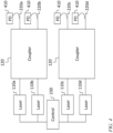
- four lasers 110a-d are connected pairwise through two couplers 120 to four outputs 220a-d, the first and second lasers 110a, 110b being connected to the first and second outputs 220a, 220b through a first coupler 120, and the third and fourth lasers 110c, 110d being connected to the third and fourth outputs 220c, 220d through a second coupler 120.
- a fraction of the light at each of the outputs is tapped off, by, for example, a suitable fiber optic coupler, and fed to a respective one of four photodiodes 410. In some embodiments fewer photodiodes 410 (e.g., one per coupler 120) are used.
- the failed laser may be shut down by the control circuit 230 and the other laser (the "spare" laser) may be put into service by the control circuit 230.
- the inputs of a four by four MN ⁇ coupler may be connected to the four outputs of embodiment of FIG. 4 , and the outputs of the four by four MN ⁇ coupler may then be the outputs of the multiple-output laser source.
- the outputs of the couplers 120 in the embodiments of FIGs. 3 and 4 may, like the outputs of the coupler 120 in the embodiment of FIG. 2 , be connected to modulators (not shown in FIGs. 3 and 4 ).
- the effects of a laser failure may be further lessened by the use of a readily replaceable laser module, e.g., a laser module that may be replaced without opening an enclosure, or removing a card from a cage or a cage from a rack.
- a readily replaceable laser module e.g., a laser module that may be replaced without opening an enclosure, or removing a card from a cage or a cage from a rack.
- the laser module is connectorized or "pluggable", and the laser module laser may be hot-swappable, i.e., it may be possible to remove a laser module and install a replacement laser module without shutting off system power, and without (i) damaging the laser module being removed, (ii) damaging the laser module being installed, (iii) damaging the circuits that the laser modules are connected to in operation, and (iv) interrupting the operation of any other data links in the system (e.g., links using other lasers than the one being replaced). In some embodiments (as discussed in further detail below) it may be possible to remove a laser module and install a replacement laser module without interrupting the operation of any data link in the system.
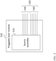
- FIG. 5 shows a schematic illustration of a pluggable laser module 510, in some embodiments.
- the laser module 510 includes a source assembly 515 and has a connector 520, and may be configured to be plugged into a corresponding connector on the front panel (e.g., on a readily accessible panel) of a piece of equipment, such as a card in a card cage (which may be in a rack), or an enclosure in a rack.
- the connector 520 includes a plurality of plugs, including one or more optical plugs (which, if there are several, may operate as a multi parallel fiber optical connector 530) and a plurality of electrical plugs (which together operate as an electrical connector 540).
- the connector 520 operates as a composite connector, including an optical connector 530 and an electrical connector 540.
- Each of the one or more optical plugs includes an optical fiber that, in operation, carries light from the laser.
- the source assembly 515 includes the multi-output laser source of claim 1 including (e.g., the source assembly 515 may include the system illustrated in FIG. 3 or the system illustrated in FIG. 4 ).
- the coupler 120 is part of a photonic integrated circuit (e.g.
- the coupler 120 may be an MN ⁇ coupler fabricated on a silicon photonic integrated circuit); this photonic integrated circuit may be in the source assembly 515, or it may instead be located downstream, e.g., on a photonics integrated circuit (e.g., together with one or more modulators) in a transmitter.
- the source assembly 515 includes only a single laser (or a single laser and a control circuit), and in which the laser in the source assembly 515 is redundant (like, e.g., each of the lasers 110a, 110b in the embodiment of FIG.
- the pluggable laser module 510 containing this source assembly 515 may be removed and replace the pluggable laser module 510 containing this source assembly 515 (and the single laser it includes) if the laser fails, without impairing the operation of any of the data links in the system (i.e., without causing a decrease in unmodulated input optical power, at any modulator, sufficient to cause the modulator to fail to meet its optical output requirements), because after the failure and during the replacement, one or more other lasers may supply the power the failed laser would have supplied had it remained fully operational.
- the electrical plugs provide electrical connections to the equipment to which the pluggable laser module 510 is connected, through which the pluggable laser module 510 receives electrical power to power the laser or lasers in the source assembly 515, and through which it may also receive control signals and send data signals (e.g., an (analog) sensing signal from a monitor photodiode in a laser in the source assembly 515).
- Each plug may, when the connector 520 is plugged into a corresponding front panel connector, engage a respective corresponding socket in the front panel connector.
- some or all of the elements shown as plugs in FIG. 5 are instead sockets configured to engage respective corresponding plugs in the front panel connector.
- the pluggable optical module 510 contains all intelligence and nonvolatile memory to operate the laser at the right temperatures and optical power levels, without assistance of the piece of equipment, or "host board" to which it is connected.
- the host board may be responsible only for providing electrical power, optionally for providing a signal line to enable or disable the laser(s), and for monitoring the health and performance of the laser module 510.
Landscapes
- Physics & Mathematics (AREA)
- Electromagnetism (AREA)
- General Physics & Mathematics (AREA)
- Optics & Photonics (AREA)
- Engineering & Computer Science (AREA)
- Computer Networks & Wireless Communication (AREA)
- Signal Processing (AREA)
- Condensed Matter Physics & Semiconductors (AREA)
- Semiconductor Lasers (AREA)
- Lasers (AREA)
- Laser Beam Processing (AREA)
Claims (10)
- Laserquelle mit mehreren Ausgängen, Folgendes umfassend:eine Vielzahl von Lasern (110a-110d); undeinen Koppler (120),wobei der Koppler eine Vielzahl von Eingängen, die jeweils mit einem Ausgang eines entsprechenden Lasers verbunden sind, und eine Vielzahl von Ausgängen (220a-220d), die jeweils mit einem Ausgang der Laserquelle mit mehreren Ausgängen verbunden sind, aufweist; undeine Steuerschaltung (230), die dazu ausgelegt ist, die Ausgangsleistung der Vielzahl von Lasern zu steuern, so dass sie während eines ersten Zeitintervalls im Wesentlichen gleich bleibt,einen Ausfall eines aus der Vielzahl von Lasern nach dem ersten Zeitintervall zu detektieren unddie Ausgangsleistung von einem oder mehreren der restlichen Laser als Antwort auf das Detektieren des Ausfalls des Lasers zu erhöhen.
- Laserquelle mit mehreren Ausgängen nach Anspruch 1, wobei der Koppler ein multimodaler Interferenzkoppler ist.
- Laserquelle mit mehreren Ausgängen nach Anspruch 1, wobei der Koppler ein kodirektionaler Koppler ist.
- Laserquelle mit mehreren Ausgängen nach Anspruch 1, wobei:die Vielzahl von Lasern zwei Laser umfasst, undder Koppler zwei Eingänge und zwei Ausgänge umfasst.
- Laserquelle mit mehreren Ausgängen nach Anspruch 4, wobei der Koppler dazu ausgelegt ist:optische Leistung an einem ersten Eingang aus den zwei Eingängen zu empfangen;einen ersten Bruchteil der empfangenen optischen Leistung zu einem ersten Ausgang aus den zwei Ausgängen zuzuführen; undeinen zweiten Bruchteil der empfangenen optischen Leistung, der im Wesentlichen dem ersten Bruchteil entspricht, zu einem zweiten Ausgang aus den zwei Ausgängen zuzuführen.
- Laserquelle mit mehreren Ausgängen nach Anspruch 1, wobei:die Vielzahl von Lasern vier Laser umfasst undder Koppler vier Eingänge und vier Ausgänge umfasst.
- Laserquelle mit mehreren Ausgängen nach Anspruch 1, wobei:die Vielzahl von Lasern acht Laser umfasst undder Koppler acht Eingänge und acht Ausgänge umfasst.
- Laserquelle mit mehreren Ausgängen nach Anspruch 1, wobei die geringste Frequenztrennung zwischen einem Paar von Lasern aus der Vielzahl von Lasern größer als 30 GHz ist.
- Laserquelle mit mehreren Ausgängen nach Anspruch 1, wobei die größte Wellenlängentrennung zwischen einem Paar von Lasern aus der Vielzahl von Lasern kleiner als 13 nm ist.
- Lasermodul (510), das Folgendes umfasst:eine Quellenanordnung (515); undeinen Verbund-Steckverbinder (520);wobei der Verbund-Steckverbinder einen optischen Steckverbinder (530) und einen elektrischen Steckverbinder (540) umfasst,wobei der elektrische Steckverbinder und der optische Steckverbinder dieselbe Eingriffsrichtung aufweisen;und wobei die Quellenanordnung eine Laserquelle mit mehreren Ausgängen nach Anspruch 1 umfasst.
Applications Claiming Priority (2)
| Application Number | Priority Date | Filing Date | Title |
|---|---|---|---|
| US201762482603P | 2017-04-06 | 2017-04-06 | |
| PCT/IB2018/000459 WO2018185562A2 (en) | 2017-04-06 | 2018-04-05 | Reliable laser light source |
Publications (3)
| Publication Number | Publication Date |
|---|---|
| EP3607674A2 EP3607674A2 (de) | 2020-02-12 |
| EP3607674B1 true EP3607674B1 (de) | 2023-10-18 |
| EP3607674C0 EP3607674C0 (de) | 2023-10-18 |
Family
ID=62223054
Family Applications (1)
| Application Number | Title | Priority Date | Filing Date |
|---|---|---|---|
| EP18726528.5A Active EP3607674B1 (de) | 2017-04-06 | 2018-04-05 | Zuverlässige laserlichtquelle |
Country Status (4)
| Country | Link |
|---|---|
| US (1) | US10404035B2 (de) |
| EP (1) | EP3607674B1 (de) |
| GB (1) | GB2575939B (de) |
| WO (1) | WO2018185562A2 (de) |
Families Citing this family (6)
| Publication number | Priority date | Publication date | Assignee | Title |
|---|---|---|---|---|
| US11121776B2 (en) | 2019-08-08 | 2021-09-14 | Rockley Photonics Limited | Faceplate pluggable remote laser source and system incorporating same |
| CN110890690B (zh) * | 2019-11-29 | 2021-04-06 | 中国科学院长春光学精密机械与物理研究所 | 一种半导体激光相干阵列及其制备方法 |
| US12015446B2 (en) * | 2020-08-04 | 2024-06-18 | Intel Corporation | Optical transceivers with multi-laser modules |
| CN112289884A (zh) * | 2020-11-11 | 2021-01-29 | 中国科学院上海微系统与信息技术研究所 | 一种激光冗余的光电集成电路 |
| CN112605068A (zh) * | 2020-12-15 | 2021-04-06 | 湖南大学 | 一种耐辐照可变焦激光清洗装置及使用方法 |
| US12176945B2 (en) * | 2022-06-14 | 2024-12-24 | Mellanox Technologies, Ltd. | Transceiver module |
Family Cites Families (7)
| Publication number | Priority date | Publication date | Assignee | Title |
|---|---|---|---|---|
| US5278688A (en) * | 1990-04-24 | 1994-01-11 | Ortel Corporation | Fault tolerant fiber optic transmission system |
| FR2807590B1 (fr) * | 2000-04-11 | 2002-06-28 | Ifotec | Dispositif de transmission a fibres optiques et a multiplexage en longueur d'onde |
| US6769812B1 (en) * | 2002-07-01 | 2004-08-03 | Nortel Networks, Ltd | Method and apparatus for forming an optical module with optical and electrical connections facing one direction |
| JP5726334B2 (ja) | 2012-01-13 | 2015-05-27 | 三菱電機株式会社 | 波長多重光通信装置 |
| CN104541461B (zh) * | 2012-07-30 | 2017-07-07 | 日本电气株式会社 | 光传输器和光通信装置 |
| US9876329B2 (en) | 2015-08-03 | 2018-01-23 | Technische Universiteit Eindhoven | One plus one redundant optical interconnects with automated recovery from light source failure |
| WO2018005991A1 (en) | 2016-07-01 | 2018-01-04 | Luxtera, Inc. | Method and system for redundant light sources by utilizing two inputs of an integrated modulator |
-
2018
- 2018-04-05 EP EP18726528.5A patent/EP3607674B1/de active Active
- 2018-04-05 WO PCT/IB2018/000459 patent/WO2018185562A2/en not_active Ceased
- 2018-04-05 GB GB1916052.2A patent/GB2575939B/en active Active
- 2018-04-05 US US15/946,345 patent/US10404035B2/en active Active
Also Published As
| Publication number | Publication date |
|---|---|
| GB201916052D0 (en) | 2019-12-18 |
| GB2575939B (en) | 2022-06-08 |
| EP3607674A2 (de) | 2020-02-12 |
| US20180294621A1 (en) | 2018-10-11 |
| EP3607674C0 (de) | 2023-10-18 |
| GB2575939A (en) | 2020-01-29 |
| WO2018185562A3 (en) | 2018-12-06 |
| WO2018185562A2 (en) | 2018-10-11 |
| US10404035B2 (en) | 2019-09-03 |
Similar Documents
| Publication | Publication Date | Title |
|---|---|---|
| EP3607674B1 (de) | Zuverlässige laserlichtquelle | |
| US11682879B2 (en) | Multi-wavelength laser system for optical data communication links and associated methods | |
| JP4336377B2 (ja) | 光学的マルチチャネルシステム | |
| JPH11121849A (ja) | 光通信装置における光増幅器 | |
| EP2077627B1 (de) | Verfahren und system zum schutz einer integrierenden fotoelektrizitätsanordnung | |
| JPWO2009060522A1 (ja) | 光送受信モジュールおよびその管理制御方法,光送受信装置ならびに波長多重光送受信装置 | |
| US10944487B2 (en) | Distribution and control of external light sources for silicon photonics based pluggable modules | |
| US11374655B1 (en) | Configurable link extender in small form factor | |
| EP0949776A2 (de) | Optischer Sender, Optischer Sender mit mehreren Wellenlängen und optisches Übertragungsverfahren | |
| US11870208B2 (en) | Optical fiber amplifier, optical fiber amplifier control method, and transmission system | |
| JP5487772B2 (ja) | 光回線終端装置、光出力異常検出回路、ponシステム、光出力異常検出方法、プログラム及び記録媒体 | |
| US11360267B2 (en) | Wavelength division multiplexing communication system and adjustment method of wavelength division multiplexing communication system | |
| US10718899B2 (en) | Optical device, wavelength division multiplexing transmitter, wavelength division multiplexing receiver, and wavelength division multiplexing transmission and receiving system | |
| US11309985B2 (en) | Light source device that includes a plurality of light sources with different wavelengths and method of controlling wavelengths | |
| CN1863026B (zh) | 采用多波长激光器的波分复用终端设备 | |
| KR100321993B1 (ko) | 광 채널 모니터링 모듈의 기준 파장 설정 장치 | |
| WO2022054228A1 (ja) | 光通信監視装置 | |
| JPH11150527A (ja) | 波長多重伝送装置 | |
| EP1231730A2 (de) | Dauerstrichlaser-Untersystem | |
| US20260010020A1 (en) | Dual wavelength generator and transceiver | |
| AU2002100264A4 (en) | Continuous wave laser subsystem | |
| US20230361878A1 (en) | Systems and methods for increasing availability in optical networks | |
| KR20240052653A (ko) | 착탈식 광원 공급 장치 및 이를 구비한 광트랜시버 | |
| KR20010077366A (ko) | 광 채널 모니터링 모듈의 기준 파장 설정 장치 | |
| JP2001308793A (ja) | 光送信方法および装置 |
Legal Events
| Date | Code | Title | Description |
|---|---|---|---|
| STAA | Information on the status of an ep patent application or granted ep patent |
Free format text: STATUS: UNKNOWN |
|
| STAA | Information on the status of an ep patent application or granted ep patent |
Free format text: STATUS: THE INTERNATIONAL PUBLICATION HAS BEEN MADE |
|
| PUAI | Public reference made under article 153(3) epc to a published international application that has entered the european phase |
Free format text: ORIGINAL CODE: 0009012 |
|
| STAA | Information on the status of an ep patent application or granted ep patent |
Free format text: STATUS: REQUEST FOR EXAMINATION WAS MADE |
|
| 17P | Request for examination filed |
Effective date: 20191105 |
|
| AK | Designated contracting states |
Kind code of ref document: A2 Designated state(s): AL AT BE BG CH CY CZ DE DK EE ES FI FR GB GR HR HU IE IS IT LI LT LU LV MC MK MT NL NO PL PT RO RS SE SI SK SM TR |
|
| AX | Request for extension of the european patent |
Extension state: BA ME |
|
| DAV | Request for validation of the european patent (deleted) | ||
| DAX | Request for extension of the european patent (deleted) | ||
| STAA | Information on the status of an ep patent application or granted ep patent |
Free format text: STATUS: EXAMINATION IS IN PROGRESS |
|
| 17Q | First examination report despatched |
Effective date: 20211014 |
|
| 111Z | Information provided on other rights and legal means of execution |
Free format text: AL AT BE BG CH CY CZ DE DK EE ES FI FR GB GR HR HU IE IS IT LT LU LV MC MK MT NL NO PL PT RO RS SE SI SK SM TR Effective date: 20221215 |
|
| GRAP | Despatch of communication of intention to grant a patent |
Free format text: ORIGINAL CODE: EPIDOSNIGR1 |
|
| STAA | Information on the status of an ep patent application or granted ep patent |
Free format text: STATUS: GRANT OF PATENT IS INTENDED |
|
| INTG | Intention to grant announced |
Effective date: 20230511 |
|
| RAP3 | Party data changed (applicant data changed or rights of an application transferred) |
Owner name: ROCKLEY PHOTONICS LIMITED |
|
| D11X | Information provided on other rights and legal means of execution (deleted) | ||
| RIN1 | Information on inventor provided before grant (corrected) |
Inventor name: SRINIVASAN, PRADEEP Inventor name: KUCHAREWSKI, NICHOLAS Inventor name: SCHRANS, THOMAS, PIERRE |
|
| GRAS | Grant fee paid |
Free format text: ORIGINAL CODE: EPIDOSNIGR3 |
|
| GRAA | (expected) grant |
Free format text: ORIGINAL CODE: 0009210 |
|
| STAA | Information on the status of an ep patent application or granted ep patent |
Free format text: STATUS: THE PATENT HAS BEEN GRANTED |
|
| RIN1 | Information on inventor provided before grant (corrected) |
Inventor name: SRINIVASAN, PRADEEP Inventor name: KUCHAREWSKI, NICHOLAS Inventor name: SCHRANS, THOMAS, PIERRE |
|
| 111Z | Information provided on other rights and legal means of execution |
Free format text: AL AT BE BG CH CY CZ DE DK EE ES FI FR GB GR HR HU IE IS IT LT LU LV MC MK MT NL NO PL PT RO RS SE SI SK SM TR Effective date: 20230815 |
|
| AK | Designated contracting states |
Kind code of ref document: B1 Designated state(s): AL AT BE BG CH CY CZ DE DK EE ES FI FR GB GR HR HU IE IS IT LI LT LU LV MC MK MT NL NO PL PT RO RS SE SI SK SM TR |
|
| REG | Reference to a national code |
Ref country code: GB Ref legal event code: FG4D |
|
| REG | Reference to a national code |
Ref country code: CH Ref legal event code: EP |
|
| REG | Reference to a national code |
Ref country code: DE Ref legal event code: R096 Ref document number: 602018059562 Country of ref document: DE |
|
| REG | Reference to a national code |
Ref country code: IE Ref legal event code: FG4D |
|
| U01 | Request for unitary effect filed |
Effective date: 20231027 |
|
| U07 | Unitary effect registered |
Designated state(s): AT BE BG DE DK EE FI FR IT LT LU LV MT NL PT SE SI Effective date: 20231102 |
|
| PG25 | Lapsed in a contracting state [announced via postgrant information from national office to epo] |
Ref country code: GR Free format text: LAPSE BECAUSE OF FAILURE TO SUBMIT A TRANSLATION OF THE DESCRIPTION OR TO PAY THE FEE WITHIN THE PRESCRIBED TIME-LIMIT Effective date: 20240119 |
|
| PG25 | Lapsed in a contracting state [announced via postgrant information from national office to epo] |
Ref country code: IS Free format text: LAPSE BECAUSE OF FAILURE TO SUBMIT A TRANSLATION OF THE DESCRIPTION OR TO PAY THE FEE WITHIN THE PRESCRIBED TIME-LIMIT Effective date: 20240218 |
|
| U20 | Renewal fee for the european patent with unitary effect paid |
Year of fee payment: 7 Effective date: 20240306 |
|
| PG25 | Lapsed in a contracting state [announced via postgrant information from national office to epo] |
Ref country code: ES Free format text: LAPSE BECAUSE OF FAILURE TO SUBMIT A TRANSLATION OF THE DESCRIPTION OR TO PAY THE FEE WITHIN THE PRESCRIBED TIME-LIMIT Effective date: 20231018 |
|
| PG25 | Lapsed in a contracting state [announced via postgrant information from national office to epo] |
Ref country code: IS Free format text: LAPSE BECAUSE OF FAILURE TO SUBMIT A TRANSLATION OF THE DESCRIPTION OR TO PAY THE FEE WITHIN THE PRESCRIBED TIME-LIMIT Effective date: 20240218 Ref country code: GR Free format text: LAPSE BECAUSE OF FAILURE TO SUBMIT A TRANSLATION OF THE DESCRIPTION OR TO PAY THE FEE WITHIN THE PRESCRIBED TIME-LIMIT Effective date: 20240119 Ref country code: ES Free format text: LAPSE BECAUSE OF FAILURE TO SUBMIT A TRANSLATION OF THE DESCRIPTION OR TO PAY THE FEE WITHIN THE PRESCRIBED TIME-LIMIT Effective date: 20231018 |
|
| PG25 | Lapsed in a contracting state [announced via postgrant information from national office to epo] |
Ref country code: RS Free format text: LAPSE BECAUSE OF FAILURE TO SUBMIT A TRANSLATION OF THE DESCRIPTION OR TO PAY THE FEE WITHIN THE PRESCRIBED TIME-LIMIT Effective date: 20231018 Ref country code: PL Free format text: LAPSE BECAUSE OF FAILURE TO SUBMIT A TRANSLATION OF THE DESCRIPTION OR TO PAY THE FEE WITHIN THE PRESCRIBED TIME-LIMIT Effective date: 20231018 Ref country code: NO Free format text: LAPSE BECAUSE OF FAILURE TO SUBMIT A TRANSLATION OF THE DESCRIPTION OR TO PAY THE FEE WITHIN THE PRESCRIBED TIME-LIMIT Effective date: 20240118 Ref country code: HR Free format text: LAPSE BECAUSE OF FAILURE TO SUBMIT A TRANSLATION OF THE DESCRIPTION OR TO PAY THE FEE WITHIN THE PRESCRIBED TIME-LIMIT Effective date: 20231018 |
|
| REG | Reference to a national code |
Ref country code: DE Ref legal event code: R097 Ref document number: 602018059562 Country of ref document: DE |
|
| PG25 | Lapsed in a contracting state [announced via postgrant information from national office to epo] |
Ref country code: CZ Free format text: LAPSE BECAUSE OF FAILURE TO SUBMIT A TRANSLATION OF THE DESCRIPTION OR TO PAY THE FEE WITHIN THE PRESCRIBED TIME-LIMIT Effective date: 20231018 |
|
| PG25 | Lapsed in a contracting state [announced via postgrant information from national office to epo] |
Ref country code: SK Free format text: LAPSE BECAUSE OF FAILURE TO SUBMIT A TRANSLATION OF THE DESCRIPTION OR TO PAY THE FEE WITHIN THE PRESCRIBED TIME-LIMIT Effective date: 20231018 |
|
| PG25 | Lapsed in a contracting state [announced via postgrant information from national office to epo] |
Ref country code: SM Free format text: LAPSE BECAUSE OF FAILURE TO SUBMIT A TRANSLATION OF THE DESCRIPTION OR TO PAY THE FEE WITHIN THE PRESCRIBED TIME-LIMIT Effective date: 20231018 Ref country code: SK Free format text: LAPSE BECAUSE OF FAILURE TO SUBMIT A TRANSLATION OF THE DESCRIPTION OR TO PAY THE FEE WITHIN THE PRESCRIBED TIME-LIMIT Effective date: 20231018 Ref country code: RO Free format text: LAPSE BECAUSE OF FAILURE TO SUBMIT A TRANSLATION OF THE DESCRIPTION OR TO PAY THE FEE WITHIN THE PRESCRIBED TIME-LIMIT Effective date: 20231018 Ref country code: CZ Free format text: LAPSE BECAUSE OF FAILURE TO SUBMIT A TRANSLATION OF THE DESCRIPTION OR TO PAY THE FEE WITHIN THE PRESCRIBED TIME-LIMIT Effective date: 20231018 |
|
| PLBE | No opposition filed within time limit |
Free format text: ORIGINAL CODE: 0009261 |
|
| STAA | Information on the status of an ep patent application or granted ep patent |
Free format text: STATUS: NO OPPOSITION FILED WITHIN TIME LIMIT |
|
| 26N | No opposition filed |
Effective date: 20240719 |
|
| PG25 | Lapsed in a contracting state [announced via postgrant information from national office to epo] |
Ref country code: MC Free format text: LAPSE BECAUSE OF FAILURE TO SUBMIT A TRANSLATION OF THE DESCRIPTION OR TO PAY THE FEE WITHIN THE PRESCRIBED TIME-LIMIT Effective date: 20231018 |
|
| PG25 | Lapsed in a contracting state [announced via postgrant information from national office to epo] |
Ref country code: MC Free format text: LAPSE BECAUSE OF FAILURE TO SUBMIT A TRANSLATION OF THE DESCRIPTION OR TO PAY THE FEE WITHIN THE PRESCRIBED TIME-LIMIT Effective date: 20231018 |
|
| REG | Reference to a national code |
Ref country code: CH Ref legal event code: PL |
|
| PG25 | Lapsed in a contracting state [announced via postgrant information from national office to epo] |
Ref country code: CH Free format text: LAPSE BECAUSE OF NON-PAYMENT OF DUE FEES Effective date: 20240430 |
|
| U20 | Renewal fee for the european patent with unitary effect paid |
Year of fee payment: 8 Effective date: 20250310 |
|
| PG25 | Lapsed in a contracting state [announced via postgrant information from national office to epo] |
Ref country code: IE Free format text: LAPSE BECAUSE OF NON-PAYMENT OF DUE FEES Effective date: 20240405 |
|
| PG25 | Lapsed in a contracting state [announced via postgrant information from national office to epo] |
Ref country code: CY Free format text: LAPSE BECAUSE OF FAILURE TO SUBMIT A TRANSLATION OF THE DESCRIPTION OR TO PAY THE FEE WITHIN THE PRESCRIBED TIME-LIMIT; INVALID AB INITIO Effective date: 20180405 |
|
| PG25 | Lapsed in a contracting state [announced via postgrant information from national office to epo] |
Ref country code: HU Free format text: LAPSE BECAUSE OF FAILURE TO SUBMIT A TRANSLATION OF THE DESCRIPTION OR TO PAY THE FEE WITHIN THE PRESCRIBED TIME-LIMIT; INVALID AB INITIO Effective date: 20180405 |
|
| PG25 | Lapsed in a contracting state [announced via postgrant information from national office to epo] |
Ref country code: TR Free format text: LAPSE BECAUSE OF FAILURE TO SUBMIT A TRANSLATION OF THE DESCRIPTION OR TO PAY THE FEE WITHIN THE PRESCRIBED TIME-LIMIT Effective date: 20231018 |
|
| PGFP | Annual fee paid to national office [announced via postgrant information from national office to epo] |
Ref country code: GB Payment date: 20260223 Year of fee payment: 9 |
|
| U20 | Renewal fee for the european patent with unitary effect paid |
Year of fee payment: 9 Effective date: 20260310 |