EP3608063A1 - Machine-outil portative et procédé de fonctionnement d'une machine-outil portative - Google Patents
Machine-outil portative et procédé de fonctionnement d'une machine-outil portative Download PDFInfo
- Publication number
- EP3608063A1 EP3608063A1 EP18187655.8A EP18187655A EP3608063A1 EP 3608063 A1 EP3608063 A1 EP 3608063A1 EP 18187655 A EP18187655 A EP 18187655A EP 3608063 A1 EP3608063 A1 EP 3608063A1
- Authority
- EP
- European Patent Office
- Prior art keywords
- motor
- magnetic field
- tool
- load state
- function
- Prior art date
- Legal status (The legal status is an assumption and is not a legal conclusion. Google has not performed a legal analysis and makes no representation as to the accuracy of the status listed.)
- Withdrawn
Links
- 238000000034 method Methods 0.000 title claims description 30
- 238000005553 drilling Methods 0.000 claims description 21
- 238000001514 detection method Methods 0.000 claims description 9
- 230000033001 locomotion Effects 0.000 description 13
- 239000004020 conductor Substances 0.000 description 9
- 238000004590 computer program Methods 0.000 description 7
- 238000005259 measurement Methods 0.000 description 5
- 238000003754 machining Methods 0.000 description 2
- 238000003825 pressing Methods 0.000 description 2
- 230000001105 regulatory effect Effects 0.000 description 2
- 238000010521 absorption reaction Methods 0.000 description 1
- 238000004891 communication Methods 0.000 description 1
- 230000001276 controlling effect Effects 0.000 description 1
- 230000001419 dependent effect Effects 0.000 description 1
- 238000005265 energy consumption Methods 0.000 description 1
- 230000003116 impacting effect Effects 0.000 description 1
Images
Classifications
-
- B—PERFORMING OPERATIONS; TRANSPORTING
- B25—HAND TOOLS; PORTABLE POWER-DRIVEN TOOLS; MANIPULATORS
- B25D—PERCUSSIVE TOOLS
- B25D11/00—Portable percussive tools with electromotor or other motor drive
- B25D11/06—Means for driving the impulse member
- B25D11/064—Means for driving the impulse member using an electromagnetic drive
-
- B—PERFORMING OPERATIONS; TRANSPORTING
- B25—HAND TOOLS; PORTABLE POWER-DRIVEN TOOLS; MANIPULATORS
- B25D—PERCUSSIVE TOOLS
- B25D11/00—Portable percussive tools with electromotor or other motor drive
-
- B—PERFORMING OPERATIONS; TRANSPORTING
- B25—HAND TOOLS; PORTABLE POWER-DRIVEN TOOLS; MANIPULATORS
- B25D—PERCUSSIVE TOOLS
- B25D2211/00—Details of portable percussive tools with electromotor or other motor drive
- B25D2211/06—Means for driving the impulse member
- B25D2211/068—Crank-actuated impulse-driving mechanisms
-
- B—PERFORMING OPERATIONS; TRANSPORTING
- B25—HAND TOOLS; PORTABLE POWER-DRIVEN TOOLS; MANIPULATORS
- B25D—PERCUSSIVE TOOLS
- B25D2216/00—Details of portable percussive machines with superimposed rotation, the rotational movement of the output shaft of a motor being modified to generate axial impacts on the tool bit
- B25D2216/0007—Details of percussion or rotation modes
- B25D2216/0015—Tools having a percussion-only mode
-
- B—PERFORMING OPERATIONS; TRANSPORTING
- B25—HAND TOOLS; PORTABLE POWER-DRIVEN TOOLS; MANIPULATORS
- B25D—PERCUSSIVE TOOLS
- B25D2216/00—Details of portable percussive machines with superimposed rotation, the rotational movement of the output shaft of a motor being modified to generate axial impacts on the tool bit
- B25D2216/0007—Details of percussion or rotation modes
- B25D2216/0023—Tools having a percussion-and-rotation mode
-
- B—PERFORMING OPERATIONS; TRANSPORTING
- B25—HAND TOOLS; PORTABLE POWER-DRIVEN TOOLS; MANIPULATORS
- B25D—PERCUSSIVE TOOLS
- B25D2250/00—General details of portable percussive tools; Components used in portable percussive tools
- B25D2250/131—Idling mode of tools
-
- B—PERFORMING OPERATIONS; TRANSPORTING
- B25—HAND TOOLS; PORTABLE POWER-DRIVEN TOOLS; MANIPULATORS
- B25D—PERCUSSIVE TOOLS
- B25D2250/00—General details of portable percussive tools; Components used in portable percussive tools
- B25D2250/221—Sensors
Definitions
- the present invention relates to a handheld power tool and a method for operating a handheld power tool.
- Handheld power tools often have load detection of an electric motor of the handheld power tool.
- the handheld power tool can then be regulated according to a determined load.
- the load is recognized by measuring the current in the electronics of the handheld power tool. The current measurement must be implemented in the power line. It is desirable to simplify and improve the load detection of an electric motor of the hand machine tool.
- the object of the present invention is to provide an improved hand tool and to improve a method for operating a hand tool.
- a handheld power tool comprises a tool holder and a motor for rotating and / or driving the tool holder.
- the handheld power tool also includes a magnetic field sensor for detecting a magnetic field of the motor that is generated by driving the tool holder.
- the hand tool is, for example, a hammer drill, a chisel hammer, a combination hammer, a core drill or a screwdriver.
- the tool holder of the hand tool is used to insert a rotatable tool, e.g. B. a drill or a chisel tool.
- the motor of the hand power tool is in particular an electric motor, for example an electric motor with an adjustable speed.
- the motor of the handheld power tool is used, in particular, to rotate the tool holder by rotating and / or striking the tool holder and / or to make a striking movement.
- the motor of the hand-held power tool serves to set the tool in rotation about the working axis by rotating the tool holder around a working axis.
- the motor of the hand-held power tool also serves to set the tool in a striking motion in the striking direction by driving the tool holder in one striking direction.
- the direction of impact is in particular parallel to the working axis.
- An object can be chiseled by the impact movement of the tool.
- the handheld power tool is set up, for example, in such a way that the tool holder does not start to drive until an object is machined.
- the motor of the hand-held power tool is put into operation, as a result of which the motor rotates, for example, at a specific motor speed.
- the engine By putting the engine into operation, only the engine rotates, e.g. B. in the case of a chisel hammer, or it rotates the motor and the tool, e.g. B. in the case of a rotary hammer.
- the striking driving of the tool holder is started.
- the tool executes striking movements in the case of the chisel hammer and executes rotational and striking movements in the case of the rotary hammer.
- the magnetic field sensor of the hand machine tool is arranged in the vicinity of the motor.
- the magnetic field sensor is, for example, a Hall sensor, a magneto-resistive sensor or a field plate sensor.
- other magnetic field sensors can also be used in the hand tool.
- the magnetic field sensor detects the magnetic field of the motor created by driving the tool holder.
- the magnetic field sensor measures a magnetic field generated by a current-carrying conductor of the motor. This means that with the help of the magnetic field sensor, a current measurement of the motor can be carried out indirectly through the magnetic field measurement.
- a current of the motor required to drive the tool holder is measured.
- a contactless and accurate current measurement of the hand machine tool in particular the motor, can take place.
- a contactless and accurate load detection of the Hand machine tool especially the motor.
- load detection of the handheld power tool can be carried out in a contactless and precise manner by means of the magnetic field sensor enables different operating states of the handheld power tool to be recognized and / or differentiated from one another.
- the magnetic field sensor is arranged in the handheld power tool in such a way that, as the magnetic field of the motor, it detects a magnetic field of a current which is picked up by the motor when the tool holder is driven.
- the magnetic field sensor is arranged in particular in the area of a power line of the motor.
- the power line of the motor is, in particular, a current-carrying conductor that connects a power supply to the hand tool, such as an accumulator or a power line, to the motor.
- a current flowing through the power line is particularly dependent on the power required to drive the tool holder. Consequently, a magnetic field generated by the current flowing through the power line also depends on the power required to drive the tool holder.
- the current intensity of the current flowing through the power line is low when the handheld power tool is operated under low load at idle, and the current strength of the current flowing through the power line is large when the handheld power tool is machining a workpiece, that is to say operated under load.
- the magnetic field sensor is arranged in the handheld power tool in such a way that, as the magnetic field of the motor, it detects the magnetic field of the current that is picked up by the motor when the tool holder is driven, an instantaneous current intensity required for driving the tool holder can be detected. This means that the current power consumption of the engine can be recorded.
- the hand tool has a control device for determining a load state of the motor as a function of the detected magnetic field.
- the control device receives the magnetic field of the motor detected by the magnetic field sensor as a signal.
- the control device determines a load state of the engine, for example by comparison with certain limit values.
- the load state of the motor depends in particular on a load applied to the hand tool.
- the load state of the engine is, for example, an idle mode and / or a low-load mode. In an idling mode, the motor of the hand-held power tool is in particular in operation, but no workpiece is machined.
- the load state of the engine can also be, for example, a load operation and / or a high load operation. In a load operation and / or high load operation, a workpiece is machined, in particular rotating and / or striking.
- the handheld power tool has a control device for determining the load state of the motor as a function of the detected magnetic field
- different load states can be recognized and differentiated from one another when the handheld power tool is in operation.
- the idle mode can be distinguished from the load mode.
- the low-load operation can be distinguished from the high-load operation.
- a pure drilling operation can be distinguished from a drilling and impact operation.
- an idle operation can be distinguished from a striking operation.
- the handheld power tool has an operating time counter for recording an operating time of the motor as a function of the determined load state.
- the control device has the operating time counter.
- the operating time counter has, for example, a storage unit.
- the operating time counter is in particular set up to separately record and store the operating time of the engine for certain detected load states.
- the operating time counter records the operating time of the engine in idle mode separately from the operating time of the engine in (high) load mode.
- the hand-held power tool has the operating time counter for recording the operating time of the motor as a function of the determined load state enables detection of the motor operating time to be improved.
- control device is set up to set, in particular to control or regulate, the handheld power tool as a function of the determined load state.
- control device is set up to set the handheld power tool as a function of the determined load state in such a way that the motor speed of the motor is changed as a function of the determined load state.
- speed of the motor can be adapted to the load condition and the energy efficiency of the motor can be improved.
- the handheld power tool can be set very well, in particular controlled or regulated very well.
- a method for operating a handheld power tool has a tool holder and a motor for rotating and / or driving the tool holder.
- the method has a step of detecting a magnetic field of the motor resulting from the driving of the tool holder.
- the method also has a step of determining a load state of the motor as a function of the detected magnetic field.
- the step of detecting the magnetic field of the motor comprises detecting a magnetic field of a current that is picked up by the motor when the tool holder is driven.
- the magnetic field of the current that is picked up by the motor when the tool holder is driven is detected, for example, by detecting the magnetic field of the current that flows through the power line described in connection with the handheld power tool.
- chiseling operation of the handheld power tool is recognized when the determined load state exceeds a certain limit value.
- the chiseling operation of the handheld power tool is recognized when the detected magnetic field and / or the current strength determined from the detected magnetic field exceeds the specific limit value.
- the control device compares the detected magnetic field and / or the current strength determined from the detected magnetic field with the determined limit value.
- the specific limit value is, for example, a specific magnetic field strength and / or a specific current strength. Because the chiseling operation of the hand tool can be detected with the aid of the magnetic field sensor, the hand tool can be set depending on whether chiseling operation is present or not.
- the method has a step of determining an operating time of the engine as a function of the determined load state.
- the operating time of the motor is determined, for example, from the operating time counter described in connection with the handheld power tool.
- the determination of the load state of the motor as a function of the magnetic field detected distinguishes an idle operation of the handheld power tool from a load operation.
- the handheld power tool can be set depending on whether it is idling or under load.
- the hand-held power tool is a hammer drill and, as a function of the magnetic field detected, the determination of the load state of the motor has a distinction between a pure drilling operation and a drilling and impact operation.
- the hammer drill has in particular three different operating states.
- the motor and the drill rotate, but no workpiece is machined.
- the motor and the drill rotate and the drill processes a workpiece by rotating around the working axis.
- the motor and the drill and the drill work a workpiece by a rotary movement about the working axis and a hammering movement in the direction of impact.
- the determination of the load state of the motor as a function of the magnetic field detected can have a distinction between the idle mode, the pure drilling mode and the drilling and impacting mode. This means that the hammer drill can be set depending on whether it is idling, drilling-only or drilling and striking.
- the hand-held power tool is a chisel hammer and the determination of the load state of the motor as a function of the magnetic field detected differentiates the idling mode from a striking mode.
- the chisel hammer has in particular two different operating states.
- the motor turns, but no workpiece is machined.
- the motor rotates and the chisel tool processes a workpiece by means of an impact movement in the impact direction.
- the handheld power tool can be set depending on whether the chisel hammer is idling or the striking mode is present.
- the method has a step of setting the handheld power tool as a function of the determined load state.
- the setting is, for example, controlling the handheld power tool as a function of the determined load condition.
- the setting can also be a regulation of the hand-held power tool depending on the determined load condition.
- the setting of the handheld power tool as a function of the determined load state comprises a change in an engine speed of the motor as a function of the determined load state.
- the control device has, for example, a processor and a computer program executed with the aid of the processor.
- the control device for example the computer program, comprises in particular an algorithm or several algorithms which are / are set up to determine a load state of the motor as a function of the detected magnetic field and / or to set the hand-held power tool as a function of the determined load state.
- the respective unit for example the processor, can be implemented in terms of hardware and / or also in terms of software.
- the unit can be designed as a device or as part of a device, for example as a computer or as a microprocessor.
- the unit can be designed as a computer program product, as a function, as a routine, as part of a program code or as an executable object.
- a computer program product such as a computer program means, for example as a storage medium, e.g. Memory card, USB stick, CD-ROM, DVD, or in the form of a downloadable file from a server in a network. This can be done, for example, in a wireless communication network by transmitting a corresponding file with the computer program product or the computer program means.
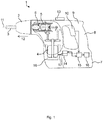
- Fig. 1 shows a hammer drill as an embodiment of the hand tool 1.
- the hammer drill 1 has a tool holder 2, in which a shaft end of a tool 3, for. B. a drill can be used.
- An accumulator 7 or a power line (not shown) supplies the motor 4 with power via a power line 17. In the in Fig. 1 In the example shown, the accumulator 7 supplies the motor 4 with current and is connected to the motor 4 through the power line 17.
- a user can hold and guide the hammer drill 1 by a handle 8.
- the handle 8 is part of a housing 9 of the rotary hammer 1.
- the rotary hammer 1 can be put into operation by means of a main button 10.
- the motor 4 By pressing the main button 10, the motor 4 is supplied with current from the accumulator 7 via the power line 17.
- the motor 4 drives the drive shaft 6 by supplying current.
- the drive shaft 6 coupled to the tool holder 2 sets the tool holder 2 in a rotational movement about a working axis 11.
- the tool 3 is thereby rotated about the working axis 11.
- the hammer drill 1 can strike the tool 3 in addition to the rotation about the working axis 11 in a striking direction 12 along the working axis 11 in a subsurface.
- the hammer drill 1 is set up such that the striking movement of the tool 3 only begins when an object is being machined.
- the tool holder 2 is driven by the striking mechanism 5.
- the striking mechanism 5 drives the tool holder 2
- the tool 3 additionally leads to the rotational movement about the working axis 11, striking movements in the striking direction 12 out.
- the hammer drill 1 has an operating selector switch 13, by means of which the tool holder 2 can be decoupled from the drive shaft 6, so that the hammer drill 1 can be operated purely by chiseling.
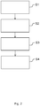
- Fig. 2 shows a schematic view of a method for operating the rotary hammer 1 from Fig. 1 ,
- a magnetic field of the motor 4 that is generated by driving the tool holder 2 is detected.
- the hammer drill 1 has a magnetic field sensor 14 adjacent to the motor 4, in particular adjacent to the power line 17, for load detection of the motor 4, as in FIG Fig. 1 to see.
- the current required for rotating and / or driving the tool holder 2 flows through the power line 17 to the motor 4 and generates a magnetic field around the power line 17.
- the magnetic field sensor 14 detects the magnetic field of the motor 4, in particular the power line 17.
- a load state of the motor 4 is determined as a function of the magnetic field detected.
- the strength of the current flowing through the power line 17 depends on the current power consumption of the motor 4 of the hammer drill 1.
- the strength of the magnetic field generated by the current flowing through the power line 17 also depends on the instantaneous power consumption of the motor 4 of the hammer drill 1.
- the motor 4 By actuating the main button 10, the motor 4 is rotated. As long as the tool 3 is not yet machining the workpiece, that is to say the hammer drill 1 is idling, the load on the motor 4 is low and the power consumption of the motor 4 is correspondingly low. In this state, a current with a low current intensity flows through the current conductor 17, which generates a weak magnetic money around the current conductor 17. If a workpiece is now machined with the tool 3, the load on the motor 4 and the power consumed by the motor 4 increase in comparison to the idle mode.
- these different load states can be determined and distinguished by a control device 15 of the rotary hammer 1 in the second step S2 of the method.
- the magnetic field sensor 14 transmits the detected magnetic field as a signal to the control device 15.
- the control device 15 compares the detected Magnetic field with certain limit values and thus determines whether there is an idle operation, a pure drilling operation or a drilling and impact operation.
- the certain limit values are certain values for the magnetic field strength. For example, the control device 15 determines that there is an idle operation if the detected magnetic field is less than a first limit value.
- control device 15 determines that there is a pure drilling operation if the detected magnetic field is greater than or equal to the first limit value and less than a second limit value. For example, the control device 15 determines that there is a drilling and striking operation if the detected magnetic field is greater than or equal to the second limit value.
- an operating time of the engine 4 is determined as a function of the determined load condition.
- the hammer drill 1, in particular the control device 15, can have, for example, an operating time counter 16 for recording the operating time of the engine 4 as a function of the determined load state, as in FIG Fig. 1 to see.
- the control device 15 and / or the operating time counter 16 have, for example, a storage unit (not shown) for storing the recorded operating time as a function of the determined load state.
- the operating time counter 16 records the operating time of the engine 4 continuously or at narrow time intervals, for example from actuation of the skin button 10, and assigns it to the load state determined by the control device 15. For example, after switching on the rotary hammer 1 via the main button 10, the operating time counter 16 first records an operating time in idle mode, followed by an operating time in drilling and hammering operation.
- the rotary hammer 1 is set, in particular controlled, as a function of the determined load condition.
- the engine speed of the engine 4 is changed as a function of the determined load state.
- the engine speed is reduced in the idle mode and the engine speed is increased in the impact and drilling mode.
Landscapes
- Engineering & Computer Science (AREA)
- Mechanical Engineering (AREA)
- Physics & Mathematics (AREA)
- Electromagnetism (AREA)
- Percussive Tools And Related Accessories (AREA)
Priority Applications (4)
| Application Number | Priority Date | Filing Date | Title |
|---|---|---|---|
| EP18187655.8A EP3608063A1 (fr) | 2018-08-07 | 2018-08-07 | Machine-outil portative et procédé de fonctionnement d'une machine-outil portative |
| PCT/EP2019/070477 WO2020030468A1 (fr) | 2018-08-07 | 2019-07-30 | Machine-outil portative et procédé pour faire fonctionner une machine-outil portative |
| EP19742639.8A EP3833510B1 (fr) | 2018-08-07 | 2019-07-30 | Machine-outil portative et procédé de fonctionnement d'une machine-outil portative |
| US17/266,517 US11597067B2 (en) | 2018-08-07 | 2019-07-30 | Hand-held power tool and method for operating a hand-held power tool |
Applications Claiming Priority (1)
| Application Number | Priority Date | Filing Date | Title |
|---|---|---|---|
| EP18187655.8A EP3608063A1 (fr) | 2018-08-07 | 2018-08-07 | Machine-outil portative et procédé de fonctionnement d'une machine-outil portative |
Publications (1)
| Publication Number | Publication Date |
|---|---|
| EP3608063A1 true EP3608063A1 (fr) | 2020-02-12 |
Family
ID=63168301
Family Applications (2)
| Application Number | Title | Priority Date | Filing Date |
|---|---|---|---|
| EP18187655.8A Withdrawn EP3608063A1 (fr) | 2018-08-07 | 2018-08-07 | Machine-outil portative et procédé de fonctionnement d'une machine-outil portative |
| EP19742639.8A Active EP3833510B1 (fr) | 2018-08-07 | 2019-07-30 | Machine-outil portative et procédé de fonctionnement d'une machine-outil portative |
Family Applications After (1)
| Application Number | Title | Priority Date | Filing Date |
|---|---|---|---|
| EP19742639.8A Active EP3833510B1 (fr) | 2018-08-07 | 2019-07-30 | Machine-outil portative et procédé de fonctionnement d'une machine-outil portative |
Country Status (3)
| Country | Link |
|---|---|
| US (1) | US11597067B2 (fr) |
| EP (2) | EP3608063A1 (fr) |
| WO (1) | WO2020030468A1 (fr) |
Families Citing this family (2)
| Publication number | Priority date | Publication date | Assignee | Title |
|---|---|---|---|---|
| WO2020257555A1 (fr) | 2019-06-21 | 2020-12-24 | The Research Foundation For The State University Of New York | Système et procédé de surveillance de brosse à dents utilisant un capteur à bobine magnéto-inductif |
| CN115008422A (zh) | 2021-03-03 | 2022-09-06 | 创科无线普通合伙 | 用于常开式动力工具的控制系统 |
Citations (2)
| Publication number | Priority date | Publication date | Assignee | Title |
|---|---|---|---|---|
| EP2884463A1 (fr) * | 2013-12-13 | 2015-06-17 | HILTI Aktiengesellschaft | Horamètre avec capteur magnétique |
| DE102015211580A1 (de) * | 2015-06-23 | 2016-12-29 | Robert Bosch Gmbh | Elektromotorvorrichtung |
Family Cites Families (19)
| Publication number | Priority date | Publication date | Assignee | Title |
|---|---|---|---|---|
| US3965669A (en) * | 1975-02-18 | 1976-06-29 | Eaton Corporation | Engine running time indicator |
| US4725996A (en) * | 1987-02-04 | 1988-02-16 | Bertram C. McIsaac | Operational timer circuit for monitoring a motor under load |
| US6249212B1 (en) * | 1994-10-05 | 2001-06-19 | Avid Marketing, Inc. | Universal electronic identification tag |
| WO2002017511A2 (fr) * | 2000-08-21 | 2002-02-28 | Koninklijke Philips Electronics N.V. | Procede de transmission d'informations et appareil faisant appel audit procede |
| US6822930B2 (en) * | 2001-06-28 | 2004-11-23 | Thomas E. Falgout, Sr | Motor run timer |
| US6735150B2 (en) * | 2002-03-28 | 2004-05-11 | Micrologic, Inc. | Method of and apparatus for distinguishing engine idling and working hours |
| DE10219950C1 (de) * | 2002-05-03 | 2003-10-30 | Hilti Ag | Pneumatisches Schlagwerk mit magnetfeldempfindlichen Sensor |
| JP2008513904A (ja) * | 2004-09-23 | 2008-05-01 | コーニンクレッカ フィリップス エレクトロニクス エヌ ヴィ | デバイスの動作の時間の監視 |
| JP5403328B2 (ja) * | 2009-02-02 | 2014-01-29 | 日立工機株式会社 | 電動穿孔工具 |
| US9460051B2 (en) * | 2009-06-22 | 2016-10-04 | Ztr Control Systems, Inc. | Method for utilization calculation on equipment including independent component |
| DE102009047106A1 (de) * | 2009-11-25 | 2011-05-26 | Robert Bosch Gmbh | Variation der Eigenfrequenz von Schwingungsmitteln in Elektrowerkzeugen |
| JP6235872B2 (ja) * | 2013-11-07 | 2017-11-22 | 株式会社マキタ | 作業工具 |
| JP6367617B2 (ja) * | 2014-06-23 | 2018-08-01 | 株式会社マキタ | 往復動式作業工具 |
| EP3023200A1 (fr) * | 2014-11-20 | 2016-05-25 | HILTI Aktiengesellschaft | Procédé de commande d'une perceuse |
| JP2018199180A (ja) * | 2017-05-26 | 2018-12-20 | 株式会社マキタ | 電動作業機 |
| CN110869170B (zh) * | 2017-09-29 | 2023-09-29 | 工机控股株式会社 | 电动工具 |
| GB201804076D0 (en) * | 2018-03-14 | 2018-04-25 | Black & Decker Inc | Hammer Drill |
| JP7139128B2 (ja) * | 2018-03-21 | 2022-09-20 | 株式会社マキタ | 作業工具 |
| US11919135B2 (en) * | 2020-07-06 | 2024-03-05 | Milwaukee Electric Tool Corporation | Automatic ramp load sense for power tools |
-
2018
- 2018-08-07 EP EP18187655.8A patent/EP3608063A1/fr not_active Withdrawn
-
2019
- 2019-07-30 WO PCT/EP2019/070477 patent/WO2020030468A1/fr not_active Ceased
- 2019-07-30 US US17/266,517 patent/US11597067B2/en active Active
- 2019-07-30 EP EP19742639.8A patent/EP3833510B1/fr active Active
Patent Citations (2)
| Publication number | Priority date | Publication date | Assignee | Title |
|---|---|---|---|---|
| EP2884463A1 (fr) * | 2013-12-13 | 2015-06-17 | HILTI Aktiengesellschaft | Horamètre avec capteur magnétique |
| DE102015211580A1 (de) * | 2015-06-23 | 2016-12-29 | Robert Bosch Gmbh | Elektromotorvorrichtung |
Also Published As
| Publication number | Publication date |
|---|---|
| WO2020030468A1 (fr) | 2020-02-13 |
| US11597067B2 (en) | 2023-03-07 |
| EP3833510B1 (fr) | 2022-09-07 |
| US20210316435A1 (en) | 2021-10-14 |
| EP3833510A1 (fr) | 2021-06-16 |
Similar Documents
| Publication | Publication Date | Title |
|---|---|---|
| DE102011104901B4 (de) | Kraftgetriebene Handwerkzeugmaschine | |
| EP0764502B1 (fr) | Appareil manuel de perçage assisté par percussion | |
| DE10304405B4 (de) | Verfahren zur Regelung einer Kernbohrmaschine | |
| EP3113911B1 (fr) | Affichage de puissance adaptatif | |
| EP3852978B1 (fr) | Machine-outil portative et procédé de fonctionnement d'une machine-outil portative | |
| DE102014211891A1 (de) | Verfahren zum Betreiben eines Elektrowerkzeuges | |
| DE10316844A1 (de) | Steuerung einer Elektrohandwerkzeugmaschine | |
| EP3833510B1 (fr) | Machine-outil portative et procédé de fonctionnement d'une machine-outil portative | |
| WO2021244788A1 (fr) | Appareil à main équipé d'un ensemble capteur pour caractériser un support usiné | |
| EP4192655A1 (fr) | Procédé d'entraînement d'un classificateur pour déterminer un état d'appareil de machine-outil portative | |
| WO2022228880A1 (fr) | Procédé d'activation et de désactivation d'un verrou de broche dans un outil électrique et outil électrique | |
| EP4368346A1 (fr) | Procédé d'opération d'une machine-outil portative | |
| EP4263137A1 (fr) | Procédé de fonctionnement d'un outil électrique portatif | |
| EP4353387A1 (fr) | Procédé de maintien d'une broche d'une machine-outil mobile | |
| DE102023200607A1 (de) | Verfahren zum Steuern einer Handwerkzeugmaschine und Handwerkzeugmaschine | |
| DE60103956T2 (de) | Schlagbohrmaschine | |
| DE102023200619A1 (de) | Verfahren zum Auswählen von Daten für ein Training einer künstlichen Intelligenz, Verfahren zum Erzeugen eines Trainingsdatensatzes, Trainingsdatensatz | |
| WO2016059017A1 (fr) | Machine-outil portative de burinage | |
| DE102014222567A1 (de) | Handwerkzeugmaschinenvorrichtung | |
| DE102015200822A1 (de) | Verfahren zum Betreiben eines Elektromotors eines Elektrowerkzeuges | |
| DE102014226369A1 (de) | Schlagwerkvorrichtung | |
| WO2019145156A1 (fr) | Procédé de commande d'une visseuse à percussion | |
| DE102023200523A1 (de) | Verfahren zum Betrieb einer Handwerkzeugmaschine | |
| DE102024207087A1 (de) | Verfahren zum Betrieb einer Handwerkzeugmaschine | |
| DE102023200526A1 (de) | Verfahren zum Betrieb einer Handwerkzeugmaschine |
Legal Events
| Date | Code | Title | Description |
|---|---|---|---|
| PUAI | Public reference made under article 153(3) epc to a published international application that has entered the european phase |
Free format text: ORIGINAL CODE: 0009012 |
|
| AK | Designated contracting states |
Kind code of ref document: A1 Designated state(s): AL AT BE BG CH CY CZ DE DK EE ES FI FR GB GR HR HU IE IS IT LI LT LU LV MC MK MT NL NO PL PT RO RS SE SI SK SM TR |
|
| AX | Request for extension of the european patent |
Extension state: BA ME |
|
| STAA | Information on the status of an ep patent application or granted ep patent |
Free format text: STATUS: THE APPLICATION IS DEEMED TO BE WITHDRAWN |
|
| 18D | Application deemed to be withdrawn |
Effective date: 20200813 |