EP3608103A1 - Procédé et dispositif permettant de stratifier un empilement constitué de plusieurs couches de substrat pour former un corps composite - Google Patents
Procédé et dispositif permettant de stratifier un empilement constitué de plusieurs couches de substrat pour former un corps composite Download PDFInfo
- Publication number
- EP3608103A1 EP3608103A1 EP19188163.0A EP19188163A EP3608103A1 EP 3608103 A1 EP3608103 A1 EP 3608103A1 EP 19188163 A EP19188163 A EP 19188163A EP 3608103 A1 EP3608103 A1 EP 3608103A1
- Authority
- EP
- European Patent Office
- Prior art keywords
- laminating
- heating
- stack
- cooling
- working position
- Prior art date
- Legal status (The legal status is an assumption and is not a legal conclusion. Google has not performed a legal analysis and makes no representation as to the accuracy of the status listed.)
- Granted
Links
Images

Classifications
-
- B—PERFORMING OPERATIONS; TRANSPORTING
- B32—LAYERED PRODUCTS
- B32B—LAYERED PRODUCTS, i.e. PRODUCTS BUILT-UP OF STRATA OF FLAT OR NON-FLAT, e.g. CELLULAR OR HONEYCOMB, FORM
- B32B41/00—Arrangements for controlling or monitoring lamination processes; Safety arrangements
-
- B—PERFORMING OPERATIONS; TRANSPORTING
- B30—PRESSES
- B30B—PRESSES IN GENERAL
- B30B1/00—Presses, using a press ram, characterised by the features of the drive therefor, pressure being transmitted directly, or through simple thrust or tension members only, to the press ram or platen
- B30B1/10—Presses, using a press ram, characterised by the features of the drive therefor, pressure being transmitted directly, or through simple thrust or tension members only, to the press ram or platen by toggle mechanism
- B30B1/16—Presses, using a press ram, characterised by the features of the drive therefor, pressure being transmitted directly, or through simple thrust or tension members only, to the press ram or platen by toggle mechanism operated by fluid-pressure means
-
- B—PERFORMING OPERATIONS; TRANSPORTING
- B30—PRESSES
- B30B—PRESSES IN GENERAL
- B30B15/00—Details of, or accessories for, presses; Auxiliary measures in connection with pressing
- B30B15/02—Dies; Inserts therefor; Mounting thereof; Moulds
- B30B15/026—Mounting of dies, platens or press rams
-
- B—PERFORMING OPERATIONS; TRANSPORTING
- B30—PRESSES
- B30B—PRESSES IN GENERAL
- B30B15/00—Details of, or accessories for, presses; Auxiliary measures in connection with pressing
- B30B15/06—Platens or press rams
- B30B15/062—Press plates
- B30B15/064—Press plates with heating or cooling means
-
- B—PERFORMING OPERATIONS; TRANSPORTING
- B32—LAYERED PRODUCTS
- B32B—LAYERED PRODUCTS, i.e. PRODUCTS BUILT-UP OF STRATA OF FLAT OR NON-FLAT, e.g. CELLULAR OR HONEYCOMB, FORM
- B32B37/00—Methods or apparatus for laminating, e.g. by curing or by ultrasonic bonding
- B32B37/06—Methods or apparatus for laminating, e.g. by curing or by ultrasonic bonding characterised by the heating method
-
- B—PERFORMING OPERATIONS; TRANSPORTING
- B32—LAYERED PRODUCTS
- B32B—LAYERED PRODUCTS, i.e. PRODUCTS BUILT-UP OF STRATA OF FLAT OR NON-FLAT, e.g. CELLULAR OR HONEYCOMB, FORM
- B32B37/00—Methods or apparatus for laminating, e.g. by curing or by ultrasonic bonding
- B32B37/08—Methods or apparatus for laminating, e.g. by curing or by ultrasonic bonding characterised by the cooling method
-
- B—PERFORMING OPERATIONS; TRANSPORTING
- B32—LAYERED PRODUCTS
- B32B—LAYERED PRODUCTS, i.e. PRODUCTS BUILT-UP OF STRATA OF FLAT OR NON-FLAT, e.g. CELLULAR OR HONEYCOMB, FORM
- B32B39/00—Layout of apparatus or plants, e.g. modular laminating systems
-
- B—PERFORMING OPERATIONS; TRANSPORTING
- B32—LAYERED PRODUCTS
- B32B—LAYERED PRODUCTS, i.e. PRODUCTS BUILT-UP OF STRATA OF FLAT OR NON-FLAT, e.g. CELLULAR OR HONEYCOMB, FORM
- B32B2425/00—Cards, e.g. identity cards, credit cards
-
- B—PERFORMING OPERATIONS; TRANSPORTING
- B32—LAYERED PRODUCTS
- B32B—LAYERED PRODUCTS, i.e. PRODUCTS BUILT-UP OF STRATA OF FLAT OR NON-FLAT, e.g. CELLULAR OR HONEYCOMB, FORM
- B32B2429/00—Carriers for sound or information
Definitions
- the invention relates to a method and a laminating device for laminating a stack consisting of a plurality of substrate layers to form a composite body, in particular document bodies, such as a security document.
- a method and a device for laminating a multilayer security document body are known, in which a thermal press with at least one movable stamp is used.
- This thermal press comprises an upper movable stamp and a lower immovable stamp.
- a press pad is assigned to each stamp.
- a laminating sheet is provided adjacent to this.
- a stack of substrate layers is provided between the laminating sheets and is laminated by the thermal press.
- several thermal presses are put into operation one after the other in order to work in a multi-stage short cycle. For example, two successive heating presses and two successive cooling presses are provided.
- the laminating sheet, the press pad and the stack are preheated.
- the stack is heated to a laminating temperature so that the individual layers are laminated together.
- the stack is cooled in a first stage and then completely cooled in the second cooling press.
- a laminating device for laminating a film-like multilayer thermoplastic film arrangement is known.
- This laminating device comprises a heating device and a cooling device which is in the direction of flow tape-like film are arranged one behind the other. By arranging the heating and cooling device in series, the film arrangement can be laminated in one step in successive steps and cooled in the next step in the next step.
- this laminating device after the laminating of the film arrangement, the heating devices arranged on both sides of the film arrangement are moved apart, so that the cooling block is retracted in this upper and lower position of the heating device and subsequently the heating block acts on the cooling block by pressing, so that this cooling block acts on the Hold down film assembly for cooling in the laminating position.
- This arrangement is complex in terms of installation space and also costly in construction.
- the invention has for its object to provide a laminating device and a method for laminating a stack consisting of several substrate layers to a composite body, in which the lamination time is reduced.
- a lamination device for laminating a stack consisting of a plurality of substrate layers to form a composite body, in particular a document body, in which a heating device and a cooling device are provided above the press table, which form a jointly movable upper lamination unit, which are thermally decoupled from one another and for the respective arrangement of the heating device or cooling device for the working position, the upper laminating unit is movable and in which a lower heating device and a lower cooling device are provided below the press table, which form a jointly movable lower laminating unit, the heating device and the cooling device being thermally decoupled from one another and for respective arrangement of the heating device or cooling device to the working position, the lower laminating unit is movable.
- This upper and lower laminating unit arranged on both sides for stacking, enables faster heating of the Substrate layers of the stack and a faster cooling of the laminated composite body, although both the heating device are moved together or simultaneously when moving the upper and lower laminating unit.
- a rapid change between the lamination and cooling is preferably achieved by means of a synchronous control for moving the upper and lower lamination units within the lamination device.
- a guide device is preferably provided on the base body, by means of which the upper and lower laminating units can be alternately transferred from a rest position to a working position.
- the heating and cooling devices can be positioned outside of a working position in the laminating device in order to enable rapid loading and unloading of the stack. This can be followed by a quick change between the heating and cooling devices by means of a simple movement to at least one hold-down device and / or laminating plate, as a result of which the process times can be reduced.
- the heating device and the cooling device preferably each have a support surface which, in the working position, can be transferred to bear against the at least one hold-down device and / or laminating plate. This enables full-surface contact and maximum energy transfer to be achieved.
- the heating and cooling device each has a pressure surface opposite the support surface, on which a press die or a pressure plate of a movable die can be positioned.
- This enables the heating or cooling devices to be moved via the press ram to the at least one hold-down device and / or the at least one laminating plate after the heating device or cooling devices have been positioned in the working position, so that full-area contacting takes place.
- this force of the press ram can be applied via the heating or cooling devices, the at least one hold-down device and / or the at least one laminating sheet are transferred to the stack in order to carry out the lamination under pressure and temperature.
- the guide device for the movable accommodation of the heating and cooling device is preferably fastened to the base body by means of a spring bearing.
- a pressing force is exerted on the heating or cooling device by means of the press ram, a movement of movement towards the stack is made possible.
- the guide device can lift the heating and cooling device slightly off the hold-down device, so that a free movement is made possible before the cooling or heating device is then pressed down again to the hold-down device.
- the upper heating and cooling device and the lower heating and cooling device are each preferably designed as a laminating unit which can be moved together. This simplifies the control of the laminating device for heating and cooling the stack.
- the thermal separation with an insulating material between the cooling and heating device prevents mutual thermal impairment.
- the heating and cooling device can be provided at the operating temperature at the same time.
- the hold-down device can be designed as a laminating sheet.
- the laminating plate preferably replaceable, can also be fastened to the hold-down device.
- a workpiece carrier can preferably be positioned on the press table, which can be transferred from a transport device to the laminating device for laminating the stack and can be returned to the transport device after laminating.
- a laminating device can be integrated into a process automation in which the workpiece carrier transports the stack of substrate layers or the composite body from station to station.
- the press table of the laminating device is preferably designed as a plate with an opening, which on the Basic body is provided.
- the workpiece carrier can preferably be positioned on the press table. Due to the design of the opening in the press table, the stack picked up by the workpiece carrier can be acted upon from both a top and a bottom by the respective heating and cooling device of the respective working temperature.
- the press table is preferably assigned an upper and a lower hold-down and / or an upper and lower laminating plate.
- the laminating sheets can either be moved to the working position or the laminating position so that they are assigned to the press table for laminating the stack, whereas when the laminated stack is cooled, the cooling device can directly attack the stack or attack it with the interposition of a hold-down device.
- the workpiece carrier preferably has a receiving frame with a recess for the at least one substrate layer, and a fixing device for holding the substrate layers in the receiving frame is provided on at least one side edge of the recess.
- This fixing device can preferably be a clamping element.
- this fixing device can also be formed by pins or spikes that penetrate the respective substrate layer.
- the base body of the laminating device preferably has a C-shaped machine frame which receives the press ram on an upper and a lower leg.
- These C-shaped machine frames have the advantage that they are easily accessible to the press table.
- a workpiece carrier can thereby be passed through the laminating device in a simple manner. As a result, such a lamination device can easily be integrated into an automation process integrated.
- the at least one hold-down device is preferably positioned to the side of the base body and can be moved from a release position into a holding position by means of a displacement device.
- the independent control of the hold-down device to the cooling and heating device has the advantage that the laminated stack remains fixed in its position by the hold-down device when changing between the heating and cooling device. As a result, the quality for producing the composite body can be increased.
- the object on which the invention is based is further achieved by a method for laminating a stack consisting of a plurality of substrate layers to form a composite body, in which a stack comprising a plurality of substrate layers in a device, in particular in a laminating device, according to one of the preceding embodiments, a press table in a working position is assigned, in which at least one hold-down device and / or at least one laminating plate is transferred into a holding position and the stack is fixed, in which an upper and lower heating device of the upper and lower laminating unit are moved into a working position to the press table for heating and laminating the stack, in which at least one movable stamp presses the upper and the lower heating device onto the at least one holding-down device and / or the at least one laminating plate and a heat and pressure transmission is initiated in the stack during a heating phase, b ei after the lamination of the stack, the at least one movable die is moved up and down and the upper and lower heating devices are lifted off
- This method enables the stack to be heated to a laminating temperature and then cooled down within a laminating device, the stack being laminated by the at least one hold-down device and / or the at least one laminating sheet during laminating and cooling and during the change between the cooling device and the heating device is held in a defined position to the press table. This can reduce the process time. The energy for heating and cooling the stack can also be reduced, since only the hold-down device and the laminating plate act as a thermal mass.
- an upper laminating unit which comprises the upper heating and cooling device
- a lower laminating unit which comprises the lower heating and cooling device
- the holding-down device presses on the stack with a preset force.
- the individual substrate layers lie due to this pre-fixing even before the start of the heating phase over the entire surface, whereby a shortening of the heating phase can be achieved.
- the heating and cooling device each have a working temperature when the laminating device is in operation in the rest position. This means that the heating device is also heated to the laminating temperature adjacent to the working position, i.e. in the rest position, and the cooling device to the cooling temperature provided for it, so that the respective process can be carried out immediately after the cooling or heating device has been positioned in the working position ,
- the temperature is monitored with at least one temperature sensor, the height of the stack with a distance sensor, the pressure force on the stack with a force sensor and / or the lamination and cooling duration with a timer.
- Process monitoring can thereby be achieved in order to simultaneously determine whether the composite body produced is a good part or a reject part.
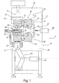
- FIG. 1 a schematic side view of a laminating device 11 according to the invention is shown.
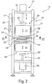
- the Figure 2 shows a schematic front view of the laminating device 11 according to FIG Figure 1 .
- This laminating device 11 is for laminating one of several Provided substrate layers 12 existing stack 14 to form a composite body.
- This composite body can be designed as a document body, in particular as a security document or value document. Further identification documents or check cards, Visa cards or the like can also be formed by the composite body.
- an ID3 document or an ID1 document can be provided in the case of a security document body.
- the ID1 document can consist of 3 to 15 substrate layers and be laminated in a working position, as will be described below.
- Security documents with an RFID chip or other electronic components can also be provided between the substrate layers or within the substrate layers, which form a composite body after lamination.
- This composite body can be cut to a final format in a subsequent cutting and / or punching process. It is also possible that the substrate layers are already added in a final format, so that the laminate has a final format after lamination.
- Thermoplastic layers in particular polycarbonate, are used as substrate layers 12, for example.
- Other materials that can be laminated with another material by pressure and temperature are also used.
- the laminating device 11 comprises a base body 16, which is designed, for example, as a C-shaped machine frame 17.
- This C-shaped machine frame 17 comprises an upper cross member 18 and a lower cross member 20.
- An upper laminating unit 29 and a lower laminating unit 30 are respectively arranged on the upper cross member 18 and the lower cross member 20.
- the upper laminating unit 29 comprises a heating device 31 and a cooling device 32.
- the lower laminating unit 30 also comprises a heating device 31 and a cooling device 32.
- the upper and lower laminating units 29, 30 are preferably constructed identically.
- Press table 19 is provided, which is also attached to the base body 16 or is assigned to the base body 16 between the upper and lower laminating units 29, 30.
- the stamp 21 can be actuated by a press for a movement.
- This can preferably be a hydraulic press, a pressure cylinder or the like.
- a toggle lever mechanism 55 can also be provided, which can be actuated by means of a pressure cylinder 56 in order to control the height of the pressure plate 22.
- further drive mechanisms can be provided which, because of their lever ratios, enable an increase in force.
- a movable punch 21 is provided, which can be moved up and down relative to the press table 19.
- This movable plunger 21 comprises a pressure plate 22 which can be controlled in height.
- a hold-down device 24 can also be provided on an underside of the press table 19. This can be designed and arranged analogously to the upper hold-down device and can also be controlled.
- the upper and lower laminating units 29, 30 are arranged in a working position 35 with respect to the respective heating device 31.
- the stack 14 can be heated and laminated after the feed movement onto the stack 14.
- the upper and lower laminating units 29, 30 can preferably be moved simultaneously by a control device 57, so that the cooling device 32 is transferred to the working position 35, the heating devices 31 being able to be arranged in a rest position outside the C-shaped frame.
- This drive device 57 can be, for example, a pressure cylinder 58 with an adjusting mechanism which engages the upper and lower laminating units 29, 30 and through which the upper and lower laminating units 29, 30 can be moved relative to the C-shaped frame 17.
- At least one hold-down 24 is assigned to the side of the C-shaped machine frame 17, which is held in place by a displacement device 25 the C-shaped machine frame 17 is attached, movable up and down, that is movable up and down parallel to the movable plunger 21.
- This hold-down 24 is, for example, L-shaped, so that an L-shaped leg 26 is aligned parallel to the press table 19 and the second L-shaped leg 27 is fastened to the displacement device 25.
- struts or other fastening options can also be provided.
- FIG 3 a workpiece carrier 45 is shown in perspective.
- Figure 4 shows a schematic sectional view of the workpiece carrier 45.
- the workpiece carrier 45 comprises a receiving frame 61 with a recess 62, wherein a bearing surface 64 for the substrate layers 12 is formed by the peripheral receiving frame 61 formed in the recess 62.
- the recess 62 corresponds in size to the contact surfaces 33 of the heating and cooling device 31, 32 or is slightly smaller.
- the size of the recess 62 is preferably selected such that it is the same size or larger than a final format of the composite body to be produced.
- At least one fixing device 63 is provided along a side edge of the receiving frame 61.
- these can be two pins, spikes, needles or the like spaced apart from one another, which penetrate the respective substrate layer 12 and thereby enable the substrate layer 12 to be positioned and aligned in the receiving frame 61.
- the fixing devices 63 for example designed as mandrels, are preferably aligned in the longitudinal axis of the card body to be produced. A wave-free expansion of the layers 12 can thereby be made possible.
- the circumferential contact surface 64 is preferably formed for an edge region of the substrate layer 12. This enables the substrate layers 12 to be fed to the workpiece carrier 45 and positioned in a processing station preceding the laminating device 11. Furthermore, before the workpiece carrier 45 is fed into the laminating station, individual substrate layers 12 can be printed and / or security features on or between the substrate layers 12 be introduced.
- the application of an IC chip or a transponder unit can also be provided.
- Such a workpiece carrier 45 with substrate layers 12 accommodated therein is fed to the press table 19.
- the press table 19 preferably has an opening which corresponds in format and / or size to the recess 62.
- the contact surface 33 of the heating and cooling device 31, 32 can be brought into contact with the lowermost substrate layer 12 through the press table 19.
- the lower hold-down device 24 and / or the lower laminating plate 36 can be designed accordingly so that the heating and cooling device 31, 32 can each assume the working position for the stack 14.
- the heating or cooling device 31, 32 are positioned above the L-shaped leg 26 of the holding-down device 24, so that the heating or cooling temperature can act directly on the stack 14 via the holding-down device 24.
- the heating and cooling devices 31, 32 are designed, for example, as a common movable laminating unit 29, 30.
- This common movable laminating unit 29, 30 is carried by a guide device 37, which preferably extends between the two C-shaped machine frames 17.
- the guide device 37 can be, for example, a linear guide, by means of which an entry and exit movement of the heating and / or cooling devices 31, 32 into and out of the working position 35 can be controlled.
- the guide device 37 is in each case resiliently supported by a bearing 38 in the feed direction of the movable plunger 21.
- the heating device 31 can be moved in the direction of the hold-down device 24.
- This pressing force is then introduced into the heating device 31 via the pressure plate 22 acting on a pressure surface 23 of the heating device 31.
- the compressive force is transmitted to the upper and / or lower holding-down device 24 and / or the laminating plate 36 via a contact surface 33 of the heating device 31.
- the pressure force and temperature introduced are transferred to the stack 14 via the holding-down device 24 and / or the laminating plate 36. The same applies to the positioning of the cooling device 32 in the working position 35.
- a laminating plate 36 can be exchangeably provided on a side of the hold-down device 24 facing the stack 14, in particular the L-shaped leg 26. Such a laminating plate 36 can be used to introduce surface structures into the uppermost layer of the stack 14.
- a method for laminating a stack 14 consisting of a plurality of substrate layers 12 to form a composite body is discussed in more detail below.
- a workpiece carrier 45 is fed to the laminating device 11, for example by means of a transport conveyor device, which is not shown in detail. This can be done, for example, using a handling device or the transport device itself.
- the workpiece carrier 45 with the substrate layers 12 applied thereon, which lie one above the other in a stack 14, is positioned in relation to the press table 19.
- the workpiece carrier 45 can be aligned with the press table 19 via the centering elements 43.
- the upper and / or lower hold-down device 24 is then moved toward the stack 12.
- the respective hold-down device 24 is transferred into a holding position with a predetermined force. In this holding position, the substrate layers 12 are positioned and fixed tightly against one another or at least slightly pressed onto one another.
- the heating device 31 of the upper and lower laminating units 29, 30 is then transferred from the rest position 34 into the working position 35.
- the cooling device 32 is moved to the left and is positioned, for example, outside the C-shaped frame 17.
- the heating device 31 is preferably already on one Laminating temperature heated.
- the heating device 31 can be created, for example, from electrically heated heating cartridges.
- the movable stamps 21 are activated, as a result of which the pressure plate 22 rests on the respective heating device 31 on the pressure surface 23 and is transferred to the holding-down device 24 for contact.
- the movable punches 21 are acted upon with a predetermined path and a predetermined pressure force.
- the laminating units 29, 30 are moved towards one another.
- the substrate layers 12 are then heated and laminated to form a composite body.
- the lamination of the composite body is monitored by sensors.
- a pressure force is monitored by means of a pressure sensor
- a path of the stamp 21 or the hold-down device 24 is monitored by a distance sensor
- the lamination temperature is monitored by a temperature sensor
- the lamination time is monitored by a timer. All sensors lead to a control device, not shown, which is used to control the laminating device 11.
- the movable punches 21 are moved up and down again. Accordingly, the heating devices 31 lift off the hold-down devices 24.
- the hold-down devices 24 remain in the preset position or in the holding position, which is established after the stack 14 has been laminated.
- the raised heating devices 31 are moved into the rest position 34 and the cooling devices 32 into the working position 35, as is shown in FIG Figure 1 is shown. Subsequently, the movable punches 21 are activated again and press the cooling devices 32 over the entire surface of the hold-down devices 24.
- the cooling device 32 is preferably fed with cooling water.
- an oil or gel medium can also be provided.
- the movable punches 21 are lifted off.
- the cooling devices 32 lift off the hold-down devices 24.
- the hold-down device 24 is then raised.
- the workpiece carrier 45 can be led out of the laminating device 11 and moved to a further processing station by means of the transport device or transferred to a magazine for stacking the composite bodies or can be made available for a further processing step.
- Laminator 33 contact surface 12.
- Substrate layer 34 Rest position 14.
- Basic body 36 Laminating sheet 17.
- Movable stamp 45 is
- Workpiece carrier 22 Pressure plate 47. Centering pin 23. Printing area 55. Toggle mechanism 24. Hold-down device 56th cylinder 25. Moving device 57. Control device 26. L-shaped leg 58. Printing cylinder 27. L-shaped leg 61. Recording frame 29. Upper laminating unit 62. recess 30. Lower laminating unit 63. Fixing device 31. Heating device 64. contact surface 32. Cooling device
Landscapes
- Engineering & Computer Science (AREA)
- Mechanical Engineering (AREA)
- Casting Or Compression Moulding Of Plastics Or The Like (AREA)
Applications Claiming Priority (1)
| Application Number | Priority Date | Filing Date | Title |
|---|---|---|---|
| DE102018119179.0A DE102018119179A1 (de) | 2018-08-07 | 2018-08-07 | Verfahren und Laminiervorrichtung zum Laminieren eines aus mehreren Substratschichten bestehenden Stapels zu einem Verbundkörper |
Publications (2)
| Publication Number | Publication Date |
|---|---|
| EP3608103A1 true EP3608103A1 (fr) | 2020-02-12 |
| EP3608103B1 EP3608103B1 (fr) | 2021-05-05 |
Family
ID=67438757
Family Applications (1)
| Application Number | Title | Priority Date | Filing Date |
|---|---|---|---|
| EP19188163.0A Active EP3608103B1 (fr) | 2018-08-07 | 2019-07-24 | Procédé et dispositif permettant de stratifier un empilement constitué de plusieurs couches de substrat pour former un corps composite |
Country Status (2)
| Country | Link |
|---|---|
| EP (1) | EP3608103B1 (fr) |
| DE (1) | DE102018119179A1 (fr) |
Cited By (3)
| Publication number | Priority date | Publication date | Assignee | Title |
|---|---|---|---|---|
| CN113211929A (zh) * | 2021-05-18 | 2021-08-06 | 深圳市华正联实业有限公司 | 一种证卡层压装置 |
| CN115339213A (zh) * | 2022-05-26 | 2022-11-15 | 安徽忠盛新型装饰材料有限公司 | 一种门板加工用热压成型装置及其操作方法 |
| EP4245536A1 (fr) * | 2022-03-18 | 2023-09-20 | Bundesdruckerei GmbH | Outil de laminage et dispositif de laminage |
Families Citing this family (2)
| Publication number | Priority date | Publication date | Assignee | Title |
|---|---|---|---|---|
| DE102022100762B3 (de) * | 2022-01-13 | 2023-05-11 | Bundesdruckerei Gmbh | Verfahren sowie Laminiervorrichtung zum Laminieren von Substratschichten zu einem Verbundkörper |
| DE102023106749A1 (de) * | 2023-03-17 | 2024-09-19 | Mb Automation Gmbh & Co. Kg | Laminiervorrichtung mit vorheizeinrichtung zum laminieren eines elektrochemischen schichtstapels |
Citations (4)
| Publication number | Priority date | Publication date | Assignee | Title |
|---|---|---|---|---|
| DE102009014249A1 (de) * | 2009-03-20 | 2010-09-23 | Michalk, Manfred, Dr. | Mehrschichtige thermoplastische laminierte Folienanordnung sowie Vorrichtung und Verfahren zum Laminieren |
| DE102009014294A1 (de) | 2009-03-25 | 2010-10-07 | Christian Emmerl | Kollisionswarnsystem |
| DE102015205539A1 (de) | 2015-03-26 | 2016-09-29 | Bundesdruckerei Gmbh | Verfahren und Vorrichtung zum Laminieren eines mehrschichten Sicherheits-Dokumentkörpers mit Deformationsüberwachung |
| EP3412458A1 (fr) * | 2017-06-07 | 2018-12-12 | Bundesdruckerei GmbH | Procédé et dispositif de laminage permettant de laminer un empilement de plusieurs couches de substrat pour former un corps composite |
Family Cites Families (1)
| Publication number | Priority date | Publication date | Assignee | Title |
|---|---|---|---|---|
| DE102012207174B4 (de) * | 2012-04-30 | 2014-08-28 | Bundesdruckerei Gmbh | Vorrichtung zum Laminieren von Laminiergut, Verfahren zum Montieren eines Presspolsters in der Vorrichtung und Verfahren zum Detektieren eines Risses in dem Presspolster |
-
2018
- 2018-08-07 DE DE102018119179.0A patent/DE102018119179A1/de not_active Withdrawn
-
2019
- 2019-07-24 EP EP19188163.0A patent/EP3608103B1/fr active Active
Patent Citations (4)
| Publication number | Priority date | Publication date | Assignee | Title |
|---|---|---|---|---|
| DE102009014249A1 (de) * | 2009-03-20 | 2010-09-23 | Michalk, Manfred, Dr. | Mehrschichtige thermoplastische laminierte Folienanordnung sowie Vorrichtung und Verfahren zum Laminieren |
| DE102009014294A1 (de) | 2009-03-25 | 2010-10-07 | Christian Emmerl | Kollisionswarnsystem |
| DE102015205539A1 (de) | 2015-03-26 | 2016-09-29 | Bundesdruckerei Gmbh | Verfahren und Vorrichtung zum Laminieren eines mehrschichten Sicherheits-Dokumentkörpers mit Deformationsüberwachung |
| EP3412458A1 (fr) * | 2017-06-07 | 2018-12-12 | Bundesdruckerei GmbH | Procédé et dispositif de laminage permettant de laminer un empilement de plusieurs couches de substrat pour former un corps composite |
Cited By (4)
| Publication number | Priority date | Publication date | Assignee | Title |
|---|---|---|---|---|
| CN113211929A (zh) * | 2021-05-18 | 2021-08-06 | 深圳市华正联实业有限公司 | 一种证卡层压装置 |
| EP4245536A1 (fr) * | 2022-03-18 | 2023-09-20 | Bundesdruckerei GmbH | Outil de laminage et dispositif de laminage |
| CN115339213A (zh) * | 2022-05-26 | 2022-11-15 | 安徽忠盛新型装饰材料有限公司 | 一种门板加工用热压成型装置及其操作方法 |
| CN115339213B (zh) * | 2022-05-26 | 2023-11-21 | 安徽忠盛新型装饰材料有限公司 | 一种门板加工用热压成型装置及其操作方法 |
Also Published As
| Publication number | Publication date |
|---|---|
| DE102018119179A1 (de) | 2020-02-13 |
| EP3608103B1 (fr) | 2021-05-05 |
Similar Documents
| Publication | Publication Date | Title |
|---|---|---|
| EP3608103B1 (fr) | Procédé et dispositif permettant de stratifier un empilement constitué de plusieurs couches de substrat pour former un corps composite | |
| EP3412458B1 (fr) | Procédé et dispositif de laminage permettant de laminer un empilement de plusieurs couches de substrat pour former un corps composite | |
| DE4112047A1 (de) | Verfahren und vorrichtung zur herstellung keramischer rohschichten fuer geschichtete, keramische elektronikkomponenten | |
| EP3608122A1 (fr) | Installation de production permettant de fabriquer des cartes de données pour documents de sécurité | |
| EP0408896A1 (fr) | Dispositif pour appliquer des À©tiquettes thermo-adhésives | |
| EP1222071B1 (fr) | Dispositif permettant de laminer par segments une structure stratifiee constituee d'au moins deux bandes en matiere plastique | |
| EP4578042A1 (fr) | Dispositif et procédé de frittage | |
| EP1110708A2 (fr) | Procédé et dispositif pour la fabrication de cartes multicouches en matière plastique | |
| EP3781410B1 (fr) | Installation de fabrication servant à produire des documents de sécurité ou des livres | |
| DE102022100762B3 (de) | Verfahren sowie Laminiervorrichtung zum Laminieren von Substratschichten zu einem Verbundkörper | |
| AT527300A4 (de) | Vorrichtung zum verbinden eines bauelements mit einem substrat | |
| EP2563591B1 (fr) | Procédé et dispositif pour imprimer des documents de valeur ou de sécurité | |
| EP4137320A1 (fr) | Appareil et procédé de fabrication discontinue d'un stratifié constitué de plusieurs substrats | |
| EP3556567A1 (fr) | Procédé et dispositif d'application d'une section de feuille adhésive séparée d'une bande adhésive à une couverture de livre | |
| DE102022106454B4 (de) | Laminierwerkzeug sowie eine Laminiervorrichtung | |
| DE102024111647B4 (de) | Zylinderplatte einer Vorrichtung zum Verbinden eines Bauelements mit einem Substrat | |
| DE102020120898B4 (de) | Verfahren zum Laminieren von mehreren folienartigen Schichten zu einem homogenen Schichtverbund | |
| AT527197B1 (de) | Vorrichtung zum verbinden eines bauelements mit einem substrat | |
| EP4215380B1 (fr) | Installation de production et procédé de production d'une carte brute ou d'un composite de cartes brutes pour documents d'identité, de valeur ou de sécurité | |
| DE102023124985A1 (de) | Vorrichtung zum Verbinden eines Bauelements mit einem Substrat | |
| DE102023124987A1 (de) | Vorrichtung zum Verbinden eines Bauelements mit einem Substrat | |
| AT527922A4 (de) | Zylinderplatte einer Vorrichtung zum Verbinden eines Bauelements mit einem Substrat | |
| DE102021004249A1 (de) | Vorrichtung und Verfahren zur diskontinuierlichen Herstellung eines Laminats aus mehreren Substraten | |
| EP3500435A1 (fr) | Installation et procédé de production de documents de valeur et de sécurité personnels à partir de morceaux de matériau de départ | |
| EP2271503A1 (fr) | Dispositif et procédé pour appliquer une pluralité d'éléments insérés dans des rabats de documents d'identité et document d'identité |
Legal Events
| Date | Code | Title | Description |
|---|---|---|---|
| PUAI | Public reference made under article 153(3) epc to a published international application that has entered the european phase |
Free format text: ORIGINAL CODE: 0009012 |
|
| STAA | Information on the status of an ep patent application or granted ep patent |
Free format text: STATUS: THE APPLICATION HAS BEEN PUBLISHED |
|
| AK | Designated contracting states |
Kind code of ref document: A1 Designated state(s): AL AT BE BG CH CY CZ DE DK EE ES FI FR GB GR HR HU IE IS IT LI LT LU LV MC MK MT NL NO PL PT RO RS SE SI SK SM TR |
|
| AX | Request for extension of the european patent |
Extension state: BA ME |
|
| STAA | Information on the status of an ep patent application or granted ep patent |
Free format text: STATUS: REQUEST FOR EXAMINATION WAS MADE |
|
| 17P | Request for examination filed |
Effective date: 20200812 |
|
| RBV | Designated contracting states (corrected) |
Designated state(s): AL AT BE BG CH CY CZ DE DK EE ES FI FR GB GR HR HU IE IS IT LI LT LU LV MC MK MT NL NO PL PT RO RS SE SI SK SM TR |
|
| GRAP | Despatch of communication of intention to grant a patent |
Free format text: ORIGINAL CODE: EPIDOSNIGR1 |
|
| STAA | Information on the status of an ep patent application or granted ep patent |
Free format text: STATUS: GRANT OF PATENT IS INTENDED |
|
| RIC1 | Information provided on ipc code assigned before grant |
Ipc: B32B 39/00 20060101ALI20201008BHEP Ipc: B32B 37/08 20060101ALI20201008BHEP Ipc: B30B 15/06 20060101ALI20201008BHEP Ipc: B32B 41/00 20060101AFI20201008BHEP Ipc: B32B 37/06 20060101ALI20201008BHEP |
|
| INTG | Intention to grant announced |
Effective date: 20201023 |
|
| GRAJ | Information related to disapproval of communication of intention to grant by the applicant or resumption of examination proceedings by the epo deleted |
Free format text: ORIGINAL CODE: EPIDOSDIGR1 |
|
| STAA | Information on the status of an ep patent application or granted ep patent |
Free format text: STATUS: REQUEST FOR EXAMINATION WAS MADE |
|
| GRAP | Despatch of communication of intention to grant a patent |
Free format text: ORIGINAL CODE: EPIDOSNIGR1 |
|
| STAA | Information on the status of an ep patent application or granted ep patent |
Free format text: STATUS: GRANT OF PATENT IS INTENDED |
|
| GRAS | Grant fee paid |
Free format text: ORIGINAL CODE: EPIDOSNIGR3 |
|
| INTC | Intention to grant announced (deleted) | ||
| GRAA | (expected) grant |
Free format text: ORIGINAL CODE: 0009210 |
|
| STAA | Information on the status of an ep patent application or granted ep patent |
Free format text: STATUS: THE PATENT HAS BEEN GRANTED |
|
| INTG | Intention to grant announced |
Effective date: 20210326 |
|
| AK | Designated contracting states |
Kind code of ref document: B1 Designated state(s): AL AT BE BG CH CY CZ DE DK EE ES FI FR GB GR HR HU IE IS IT LI LT LU LV MC MK MT NL NO PL PT RO RS SE SI SK SM TR |
|
| REG | Reference to a national code |
Ref country code: GB Ref legal event code: FG4D Free format text: NOT ENGLISH |
|
| REG | Reference to a national code |
Ref country code: CH Ref legal event code: EP |
|
| REG | Reference to a national code |
Ref country code: AT Ref legal event code: REF Ref document number: 1389312 Country of ref document: AT Kind code of ref document: T Effective date: 20210515 |
|
| REG | Reference to a national code |
Ref country code: IE Ref legal event code: FG4D Free format text: LANGUAGE OF EP DOCUMENT: GERMAN |
|
| REG | Reference to a national code |
Ref country code: DE Ref legal event code: R096 Ref document number: 502019001358 Country of ref document: DE |
|
| REG | Reference to a national code |
Ref country code: LT Ref legal event code: MG9D |
|
| PG25 | Lapsed in a contracting state [announced via postgrant information from national office to epo] |
Ref country code: BG Free format text: LAPSE BECAUSE OF FAILURE TO SUBMIT A TRANSLATION OF THE DESCRIPTION OR TO PAY THE FEE WITHIN THE PRESCRIBED TIME-LIMIT Effective date: 20210805 Ref country code: LT Free format text: LAPSE BECAUSE OF FAILURE TO SUBMIT A TRANSLATION OF THE DESCRIPTION OR TO PAY THE FEE WITHIN THE PRESCRIBED TIME-LIMIT Effective date: 20210505 Ref country code: HR Free format text: LAPSE BECAUSE OF FAILURE TO SUBMIT A TRANSLATION OF THE DESCRIPTION OR TO PAY THE FEE WITHIN THE PRESCRIBED TIME-LIMIT Effective date: 20210505 Ref country code: FI Free format text: LAPSE BECAUSE OF FAILURE TO SUBMIT A TRANSLATION OF THE DESCRIPTION OR TO PAY THE FEE WITHIN THE PRESCRIBED TIME-LIMIT Effective date: 20210505 |
|
| PG25 | Lapsed in a contracting state [announced via postgrant information from national office to epo] |
Ref country code: GR Free format text: LAPSE BECAUSE OF FAILURE TO SUBMIT A TRANSLATION OF THE DESCRIPTION OR TO PAY THE FEE WITHIN THE PRESCRIBED TIME-LIMIT Effective date: 20210806 Ref country code: IS Free format text: LAPSE BECAUSE OF FAILURE TO SUBMIT A TRANSLATION OF THE DESCRIPTION OR TO PAY THE FEE WITHIN THE PRESCRIBED TIME-LIMIT Effective date: 20210905 Ref country code: NO Free format text: LAPSE BECAUSE OF FAILURE TO SUBMIT A TRANSLATION OF THE DESCRIPTION OR TO PAY THE FEE WITHIN THE PRESCRIBED TIME-LIMIT Effective date: 20210805 Ref country code: LV Free format text: LAPSE BECAUSE OF FAILURE TO SUBMIT A TRANSLATION OF THE DESCRIPTION OR TO PAY THE FEE WITHIN THE PRESCRIBED TIME-LIMIT Effective date: 20210505 Ref country code: PL Free format text: LAPSE BECAUSE OF FAILURE TO SUBMIT A TRANSLATION OF THE DESCRIPTION OR TO PAY THE FEE WITHIN THE PRESCRIBED TIME-LIMIT Effective date: 20210505 Ref country code: RS Free format text: LAPSE BECAUSE OF FAILURE TO SUBMIT A TRANSLATION OF THE DESCRIPTION OR TO PAY THE FEE WITHIN THE PRESCRIBED TIME-LIMIT Effective date: 20210505 Ref country code: SE Free format text: LAPSE BECAUSE OF FAILURE TO SUBMIT A TRANSLATION OF THE DESCRIPTION OR TO PAY THE FEE WITHIN THE PRESCRIBED TIME-LIMIT Effective date: 20210505 Ref country code: PT Free format text: LAPSE BECAUSE OF FAILURE TO SUBMIT A TRANSLATION OF THE DESCRIPTION OR TO PAY THE FEE WITHIN THE PRESCRIBED TIME-LIMIT Effective date: 20210906 |
|
| REG | Reference to a national code |
Ref country code: NL Ref legal event code: MP Effective date: 20210505 |
|
| PG25 | Lapsed in a contracting state [announced via postgrant information from national office to epo] |
Ref country code: NL Free format text: LAPSE BECAUSE OF FAILURE TO SUBMIT A TRANSLATION OF THE DESCRIPTION OR TO PAY THE FEE WITHIN THE PRESCRIBED TIME-LIMIT Effective date: 20210505 |
|
| PG25 | Lapsed in a contracting state [announced via postgrant information from national office to epo] |
Ref country code: CZ Free format text: LAPSE BECAUSE OF FAILURE TO SUBMIT A TRANSLATION OF THE DESCRIPTION OR TO PAY THE FEE WITHIN THE PRESCRIBED TIME-LIMIT Effective date: 20210505 Ref country code: DK Free format text: LAPSE BECAUSE OF FAILURE TO SUBMIT A TRANSLATION OF THE DESCRIPTION OR TO PAY THE FEE WITHIN THE PRESCRIBED TIME-LIMIT Effective date: 20210505 Ref country code: SM Free format text: LAPSE BECAUSE OF FAILURE TO SUBMIT A TRANSLATION OF THE DESCRIPTION OR TO PAY THE FEE WITHIN THE PRESCRIBED TIME-LIMIT Effective date: 20210505 Ref country code: RO Free format text: LAPSE BECAUSE OF FAILURE TO SUBMIT A TRANSLATION OF THE DESCRIPTION OR TO PAY THE FEE WITHIN THE PRESCRIBED TIME-LIMIT Effective date: 20210505 Ref country code: SK Free format text: LAPSE BECAUSE OF FAILURE TO SUBMIT A TRANSLATION OF THE DESCRIPTION OR TO PAY THE FEE WITHIN THE PRESCRIBED TIME-LIMIT Effective date: 20210505 Ref country code: ES Free format text: LAPSE BECAUSE OF FAILURE TO SUBMIT A TRANSLATION OF THE DESCRIPTION OR TO PAY THE FEE WITHIN THE PRESCRIBED TIME-LIMIT Effective date: 20210505 Ref country code: EE Free format text: LAPSE BECAUSE OF FAILURE TO SUBMIT A TRANSLATION OF THE DESCRIPTION OR TO PAY THE FEE WITHIN THE PRESCRIBED TIME-LIMIT Effective date: 20210505 |
|
| REG | Reference to a national code |
Ref country code: DE Ref legal event code: R097 Ref document number: 502019001358 Country of ref document: DE |
|
| PLBE | No opposition filed within time limit |
Free format text: ORIGINAL CODE: 0009261 |
|
| STAA | Information on the status of an ep patent application or granted ep patent |
Free format text: STATUS: NO OPPOSITION FILED WITHIN TIME LIMIT |
|
| PG25 | Lapsed in a contracting state [announced via postgrant information from national office to epo] |
Ref country code: MC Free format text: LAPSE BECAUSE OF FAILURE TO SUBMIT A TRANSLATION OF THE DESCRIPTION OR TO PAY THE FEE WITHIN THE PRESCRIBED TIME-LIMIT Effective date: 20210505 |
|
| REG | Reference to a national code |
Ref country code: BE Ref legal event code: MM Effective date: 20210731 |
|
| 26N | No opposition filed |
Effective date: 20220208 |
|
| PG25 | Lapsed in a contracting state [announced via postgrant information from national office to epo] |
Ref country code: IS Free format text: LAPSE BECAUSE OF FAILURE TO SUBMIT A TRANSLATION OF THE DESCRIPTION OR TO PAY THE FEE WITHIN THE PRESCRIBED TIME-LIMIT Effective date: 20210905 Ref country code: LU Free format text: LAPSE BECAUSE OF NON-PAYMENT OF DUE FEES Effective date: 20210724 Ref country code: AL Free format text: LAPSE BECAUSE OF FAILURE TO SUBMIT A TRANSLATION OF THE DESCRIPTION OR TO PAY THE FEE WITHIN THE PRESCRIBED TIME-LIMIT Effective date: 20210505 |
|
| PG25 | Lapsed in a contracting state [announced via postgrant information from national office to epo] |
Ref country code: IT Free format text: LAPSE BECAUSE OF FAILURE TO SUBMIT A TRANSLATION OF THE DESCRIPTION OR TO PAY THE FEE WITHIN THE PRESCRIBED TIME-LIMIT Effective date: 20210505 Ref country code: IE Free format text: LAPSE BECAUSE OF NON-PAYMENT OF DUE FEES Effective date: 20210724 Ref country code: BE Free format text: LAPSE BECAUSE OF NON-PAYMENT OF DUE FEES Effective date: 20210731 |
|
| REG | Reference to a national code |
Ref country code: CH Ref legal event code: PL |
|
| PG25 | Lapsed in a contracting state [announced via postgrant information from national office to epo] |
Ref country code: LI Free format text: LAPSE BECAUSE OF NON-PAYMENT OF DUE FEES Effective date: 20220731 Ref country code: CH Free format text: LAPSE BECAUSE OF NON-PAYMENT OF DUE FEES Effective date: 20220731 |
|
| PG25 | Lapsed in a contracting state [announced via postgrant information from national office to epo] |
Ref country code: CY Free format text: LAPSE BECAUSE OF FAILURE TO SUBMIT A TRANSLATION OF THE DESCRIPTION OR TO PAY THE FEE WITHIN THE PRESCRIBED TIME-LIMIT Effective date: 20210505 |
|
| P01 | Opt-out of the competence of the unified patent court (upc) registered |
Effective date: 20230526 |
|
| PG25 | Lapsed in a contracting state [announced via postgrant information from national office to epo] |
Ref country code: HU Free format text: LAPSE BECAUSE OF FAILURE TO SUBMIT A TRANSLATION OF THE DESCRIPTION OR TO PAY THE FEE WITHIN THE PRESCRIBED TIME-LIMIT; INVALID AB INITIO Effective date: 20190724 |
|
| PG25 | Lapsed in a contracting state [announced via postgrant information from national office to epo] |
Ref country code: MK Free format text: LAPSE BECAUSE OF FAILURE TO SUBMIT A TRANSLATION OF THE DESCRIPTION OR TO PAY THE FEE WITHIN THE PRESCRIBED TIME-LIMIT Effective date: 20210505 |
|
| PG25 | Lapsed in a contracting state [announced via postgrant information from national office to epo] |
Ref country code: TR Free format text: LAPSE BECAUSE OF FAILURE TO SUBMIT A TRANSLATION OF THE DESCRIPTION OR TO PAY THE FEE WITHIN THE PRESCRIBED TIME-LIMIT Effective date: 20210505 |
|
| PG25 | Lapsed in a contracting state [announced via postgrant information from national office to epo] |
Ref country code: MT Free format text: LAPSE BECAUSE OF FAILURE TO SUBMIT A TRANSLATION OF THE DESCRIPTION OR TO PAY THE FEE WITHIN THE PRESCRIBED TIME-LIMIT Effective date: 20210505 |
|
| REG | Reference to a national code |
Ref country code: AT Ref legal event code: MM01 Ref document number: 1389312 Country of ref document: AT Kind code of ref document: T Effective date: 20240724 |
|
| PGFP | Annual fee paid to national office [announced via postgrant information from national office to epo] |
Ref country code: DE Payment date: 20250722 Year of fee payment: 7 |
|
| PGFP | Annual fee paid to national office [announced via postgrant information from national office to epo] |
Ref country code: GB Payment date: 20250724 Year of fee payment: 7 |
|
| PG25 | Lapsed in a contracting state [announced via postgrant information from national office to epo] |
Ref country code: AT Free format text: LAPSE BECAUSE OF NON-PAYMENT OF DUE FEES Effective date: 20240724 |
|
| PGFP | Annual fee paid to national office [announced via postgrant information from national office to epo] |
Ref country code: FR Payment date: 20250723 Year of fee payment: 7 |
|
| PGFP | Annual fee paid to national office [announced via postgrant information from national office to epo] |
Ref country code: AT Payment date: 20260410 Year of fee payment: 5 |