EP3608193B1 - Appareil de commande électrique pour un véhicule ainsi que système correspondant et procédé de fonctionnement d'un véhicule - Google Patents
Appareil de commande électrique pour un véhicule ainsi que système correspondant et procédé de fonctionnement d'un véhicule Download PDFInfo
- Publication number
- EP3608193B1 EP3608193B1 EP19180236.2A EP19180236A EP3608193B1 EP 3608193 B1 EP3608193 B1 EP 3608193B1 EP 19180236 A EP19180236 A EP 19180236A EP 3608193 B1 EP3608193 B1 EP 3608193B1
- Authority
- EP
- European Patent Office
- Prior art keywords
- supply connection
- control device
- outputs
- energy supply
- energy
- Prior art date
- Legal status (The legal status is an assumption and is not a legal conclusion. Google has not performed a legal analysis and makes no representation as to the accuracy of the status listed.)
- Active
Links
Images
Classifications
-
- B—PERFORMING OPERATIONS; TRANSPORTING
- B60—VEHICLES IN GENERAL
- B60L—PROPULSION OF ELECTRICALLY-PROPELLED VEHICLES; SUPPLYING ELECTRIC POWER FOR AUXILIARY EQUIPMENT OF ELECTRICALLY-PROPELLED VEHICLES; ELECTRODYNAMIC BRAKE SYSTEMS FOR VEHICLES IN GENERAL; MAGNETIC SUSPENSION OR LEVITATION FOR VEHICLES; MONITORING OPERATING VARIABLES OF ELECTRICALLY-PROPELLED VEHICLES; ELECTRIC SAFETY DEVICES FOR ELECTRICALLY-PROPELLED VEHICLES
- B60L1/00—Supplying electric power to auxiliary equipment of vehicles
-
- B—PERFORMING OPERATIONS; TRANSPORTING
- B60—VEHICLES IN GENERAL
- B60R—VEHICLES, VEHICLE FITTINGS, OR VEHICLE PARTS, NOT OTHERWISE PROVIDED FOR
- B60R16/00—Electric or fluid circuits specially adapted for vehicles and not otherwise provided for; Arrangement of elements of electric or fluid circuits specially adapted for vehicles and not otherwise provided for
- B60R16/02—Electric or fluid circuits specially adapted for vehicles and not otherwise provided for; Arrangement of elements of electric or fluid circuits specially adapted for vehicles and not otherwise provided for electric constitutive elements
-
- B—PERFORMING OPERATIONS; TRANSPORTING
- B60—VEHICLES IN GENERAL
- B60R—VEHICLES, VEHICLE FITTINGS, OR VEHICLE PARTS, NOT OTHERWISE PROVIDED FOR
- B60R16/00—Electric or fluid circuits specially adapted for vehicles and not otherwise provided for; Arrangement of elements of electric or fluid circuits specially adapted for vehicles and not otherwise provided for
- B60R16/02—Electric or fluid circuits specially adapted for vehicles and not otherwise provided for; Arrangement of elements of electric or fluid circuits specially adapted for vehicles and not otherwise provided for electric constitutive elements
- B60R16/03—Electric or fluid circuits specially adapted for vehicles and not otherwise provided for; Arrangement of elements of electric or fluid circuits specially adapted for vehicles and not otherwise provided for electric constitutive elements for supply of electrical power to vehicle subsystems or for
-
- B—PERFORMING OPERATIONS; TRANSPORTING
- B60—VEHICLES IN GENERAL
- B60W—CONJOINT CONTROL OF VEHICLE SUB-UNITS OF DIFFERENT TYPE OR DIFFERENT FUNCTION; CONTROL SYSTEMS SPECIALLY ADAPTED FOR HYBRID VEHICLES; ROAD VEHICLE DRIVE CONTROL SYSTEMS FOR PURPOSES NOT RELATED TO THE CONTROL OF A PARTICULAR SUB-UNIT
- B60W50/00—Details of control systems for road vehicle drive control not related to the control of a particular sub-unit, e.g. process diagnostic or vehicle driver interfaces
- B60W50/02—Ensuring safety in case of control system failures, e.g. by diagnosing, circumventing or fixing failures
- B60W50/023—Avoiding failures by using redundant parts
-
- F—MECHANICAL ENGINEERING; LIGHTING; HEATING; WEAPONS; BLASTING
- F16—ENGINEERING ELEMENTS AND UNITS; GENERAL MEASURES FOR PRODUCING AND MAINTAINING EFFECTIVE FUNCTIONING OF MACHINES OR INSTALLATIONS; THERMAL INSULATION IN GENERAL
- F16H—GEARING
- F16H61/00—Control functions within control units of change-speed- or reversing-gearings for conveying rotary motion ; Control of exclusively fluid gearing, friction gearing, gearings with endless flexible members or other particular types of gearing
- F16H61/0003—Arrangement or mounting of elements of the control apparatus, e.g. valve assemblies or snapfittings of valves; Arrangements of the control unit on or in the transmission gearbox
- F16H61/0006—Electronic control units for transmission control, e.g. connectors, casings or circuit boards
-
- F—MECHANICAL ENGINEERING; LIGHTING; HEATING; WEAPONS; BLASTING
- F16—ENGINEERING ELEMENTS AND UNITS; GENERAL MEASURES FOR PRODUCING AND MAINTAINING EFFECTIVE FUNCTIONING OF MACHINES OR INSTALLATIONS; THERMAL INSULATION IN GENERAL
- F16H—GEARING
- F16H61/00—Control functions within control units of change-speed- or reversing-gearings for conveying rotary motion ; Control of exclusively fluid gearing, friction gearing, gearings with endless flexible members or other particular types of gearing
- F16H61/12—Detecting malfunction or potential malfunction, e.g. fail safe ; Circumventing or fixing failures
-
- F—MECHANICAL ENGINEERING; LIGHTING; HEATING; WEAPONS; BLASTING
- F16—ENGINEERING ELEMENTS AND UNITS; GENERAL MEASURES FOR PRODUCING AND MAINTAINING EFFECTIVE FUNCTIONING OF MACHINES OR INSTALLATIONS; THERMAL INSULATION IN GENERAL
- F16H—GEARING
- F16H61/00—Control functions within control units of change-speed- or reversing-gearings for conveying rotary motion ; Control of exclusively fluid gearing, friction gearing, gearings with endless flexible members or other particular types of gearing
- F16H61/12—Detecting malfunction or potential malfunction, e.g. fail safe ; Circumventing or fixing failures
- F16H2061/122—Avoiding failures by using redundant parts
-
- F—MECHANICAL ENGINEERING; LIGHTING; HEATING; WEAPONS; BLASTING
- F16—ENGINEERING ELEMENTS AND UNITS; GENERAL MEASURES FOR PRODUCING AND MAINTAINING EFFECTIVE FUNCTIONING OF MACHINES OR INSTALLATIONS; THERMAL INSULATION IN GENERAL
- F16H—GEARING
- F16H61/00—Control functions within control units of change-speed- or reversing-gearings for conveying rotary motion ; Control of exclusively fluid gearing, friction gearing, gearings with endless flexible members or other particular types of gearing
- F16H61/12—Detecting malfunction or potential malfunction, e.g. fail safe ; Circumventing or fixing failures
- F16H2061/1256—Detecting malfunction or potential malfunction, e.g. fail safe ; Circumventing or fixing failures characterised by the parts or units where malfunctioning was assumed or detected
- F16H2061/1292—Detecting malfunction or potential malfunction, e.g. fail safe ; Circumventing or fixing failures characterised by the parts or units where malfunctioning was assumed or detected the failing part is the power supply, e.g. the electric power supply
Definitions
- the invention relates to the field of control devices for vehicles, in particular for commercial vehicles such as trucks or the like, or for a passenger car.
- Control devices are known and are mainly used in vehicles to supply and/or control components of the vehicle.
- Components refer here in particular to electrical or electromechanical components.
- the control device usually includes an energy supply connection and outputs for supplying and/or for controlling the components.
- a control circuit is also provided. Energy is thus supplied to a control unit via the power supply connection, with which components connected to outputs of the control unit are then controlled as a function of the control unit.
- data or switching signals for example from sensors or switches, are usually available to the control unit of the control device in order to also supply the controlled components as a function of these signals.
- EP 0 692 396 B1 discloses, for example, a control device that can be installed in a trailer of a towing vehicle.
- the control unit is used to control the lighting and signaling system of the trailer vehicle in the trailer. To do this, the control unit only receives a control signal via one or two data network connections and a power supply from the towing vehicle.
- control devices are used during operation of the vehicle in addition to comfort functions, in particular for safety-related applications.
- the failure of a control device for a safety-relevant application can therefore represent a danger emanating from the vehicle and jeopardize safe driving conditions.
- control units are used to control brake actuators or in the area of manual transmissions.
- the danger of a failing control unit for the brake actuation is immediately apparent.
- a failure of a brake control device can therefore mean that braking in an emergency, but also in normal operation, cannot be carried out as desired or not at all.
- the invention relates to an electrical control unit for a vehicle or a vehicle trailer.
- the vehicle is, for example, a commercial vehicle, such as a truck or the like. According to an alternative, the vehicle is a passenger car.
- the control device includes a control unit for operating the control device.
- the control unit is, for example, an electronic or microelectronic control unit.
- An electronic or microelectronic control unit preferably has a plurality of inputs and outputs, it being possible for output signals to be generated at the outputs as a function of input signals at the inputs.
- the control unit has a logic circuit and/or a processor and a memory with a program code. The program code is loaded from the memory into the processor and executed there in order to generate the output signals depending on the input signals and also depending on the program code.
- control device includes a first power supply connection and a second power supply connection.
- control device also has outputs.
- the outputs are used for the electrically controllable connection of components.
- the components are preferably electrical or electro-mechanical components.
- Activation also includes, in particular, electrical supply of components that can be connected to the control unit in a controllable manner.
- the controller is operable to operate the controller in a first mode and in a second mode.
- a first mode a first number of outputs can be controlled with energy from the first energy supply connection.
- a second mode a second number of outputs can be controlled with energy from the second energy supply connection.
- the second number of outputs that can be controlled by the second energy supply connection in the second mode is less than the first number of outputs that can be controlled by the first energy supply connection in the first mode.
- Outputs are accordingly assigned to the first number and the second number or only to the first number. Accordingly, there are outputs that are only assigned to the first number and can therefore only be controlled in the first mode with energy from the first energy supply connection. There are also outputs that are assigned to the first number and the second number and can therefore be driven in the first mode with energy from the first energy supply connection and in the second mode with energy from the second energy supply connection.
- all of the outputs are associated with the first number and only some of the outputs are also associated with the second number.
- the control device is thus designed in such a way that it switches from a first mode to a second mode via the first power supply connection in the event of a disrupted power supply. Consequently, the control device is then supplied with energy from the second energy supply connection in order to use it to control some of the components that can be connected to the outputs.
- the function of particularly safety-relevant components can thus continue to be maintained, while less relevant functions or functions that are not even relevant to safety are suppressed.
- the energy consumption in the second mode is limited compared to the first mode in that not all outputs can be controlled. This results in the further possibility of realizing the second energy connection by means of contacts which, compared to the contacts for the first energy supply connection, are designed for lower current intensities at the same voltage. Such contacts for the second power supply connection are cheaper than contacts for the first power supply connection.
- At least one first contact partner of the first energy supply connection has a lower line resistance than at least one further first contact partner of the second energy supply connection.
- a contact partner designates a contact pin or a contact sleeve here, for example.
- the line resistance of a contact partner is to be regarded here in particular as the resistance of a contact partner that lies between two areas of the contact partner, namely between an area in which one contact partner can be electrically conductively connected to another contact partner and an area with which the contact partner can be connected to a Line or forwarding is connected in the control unit.
- the line resistance also depends on the cross-section. If the contact partners are in the form of pins according to one embodiment, a high line resistance can also be referred to as a small cross section or a low line resistance can also be referred to as a large cross section of the contact partner if the pins are made of the same material and have the same length.
- the control unit has at least one signal connection.
- the signal connection serves to supply control signals to the control device and in particular to the control unit.
- the signal connection has several contact partners.
- the contact partners of the signal connection have essentially the same line resistance.
- the line resistance of a contact partner of the signal connection and the line resistance of at least the further first contact partner of the second power supply connection are essentially the same.
- the contact partners of the signal connection and at least the further first contact partner of the second power supply connection are essentially identical.
- a single standardized control device plug can be used in order to provide signals for the signal connection on the one hand and the power supply of the control device on the other.
- Standardized control unit plugs or control unit plug connectors usually have a number of contact partners that are suitable for being electrically connected to complementary contact partners of a control unit. In this case, only two of the contact partners are designed in standardized control device plugs in order to provide a voltage or current supply for an energy supply connection. The other contact partners usually have a higher line resistance.
- the second power supply connection is provided by one or more contact partners that have the same line resistance as the contact partner(s) of the signal connection, the second power supply connection can be connected to contact partners in the control unit connector or control unit connector, which are usually used for a Signal transmission are used. This is in turn possible since the control device has to be supplied with comparatively less energy via the second energy supply connection than via the first energy supply connection during operation.
- the use of the electrical control unit is more economical and can also be integrated into an existing structure, for example.
- the first energy supply connection comprises at least one first contact partner for supplying a voltage potential, which is preferably positive.
- the second power supply connection includes at least one further first contact partner, which is also used to supply a voltage potential, which is preferably also positive.
- both energy supply connections have a common negative voltage potential, it being ensured in any case that the positive voltage potentials are provided separately for each of the energy supply connections.
- control unit is a shift control unit of a transmission control, preferably an electrical control unit of an automatic or semi-automatic transmission control.
- switching control devices are also called Transmission Control Unit (TCU).
- TCU Transmission Control Unit
- AMT automatic manual transmission
- a control device designed as a shift control device according to the invention is advantageous for ensuring a safe driving condition of a vehicle even if a supply line of the shift control device, which is connected to the first power supply connection, is interrupted.
- it can be determined by the control unit that in the second mode, in any case, the outputs are supplied with energy that make it possible for the transmission of a vehicle in such a gear ratio, in which an engine brake is effective.
- the control unit it can be ensured, for example, that when a vehicle is driving downhill and a power supply fails via the first power supply connection in the second mode of the control unit, components of the brake system are less stressed.
- control unit is set up to control at least one component, which is a valve, with at least one of the outputs.
- the valve comprises an electrical magnetic valve component and/or a pneumatic or hydraulic valve component.
- the valve is a solenoid valve.
- control unit is advantageously designed in such a way that it provides the energy required to switch a valve at at least one output.
- the first energy supply connection is set up to be connected to a primary energy source.
- the second energy supply connection is set up to be connected to an auxiliary energy source.
- control unit makes it possible to connect the first energy supply connection to the main circuit of a vehicle, for example, which includes the vehicle battery and the alternator, for example.
- the second energy supply connection is designed in such a way that it can be connected to an energy source which, for example if the primary energy source fails, still supplies sufficient energy to supply the control device in the second mode. It is therefore possible to operate the control device to a limited extent even if the primary energy source fails.
- the invention includes a system with a controller according to one of the aforementioned embodiments.
- the system also includes at least a component that is an electrical or electro-mechanical component.
- the at least one component can be electrically connected to at least one of the outputs or is operationally connected.
- the system has a primary energy source and an auxiliary energy source.
- the primary energy source is electrically connectable or operationally connected to the first energy supply connection and the auxiliary energy source is electrically connectable to the second energy supply connection.
- the at least one component comprises at least a first and a second component. At least during operation, the first component is connected to a first one of the outputs and the second component is connected to a second one of the outputs. According to the embodiment, the first and the second output are associated with the first number of outputs. Also, only the second output of the first and second outputs is also associated with the second plurality of outputs. Accordingly, the first output is not associated with the second number of outputs.
- the first and second components can be controlled in the first mode and only the second component can be controlled in the second mode.
- the maximum energy that must be provided by the second energy supply connection for activation is lower than the maximum energy that must be provided by the first energy supply connection.
- a correspondingly more favorable design of the contact partners of the second energy supply connection is therefore possible.
- the invention also includes a method for operating a vehicle by controlling components with a control device according to one of the aforementioned specific embodiments or with a system according to one of the aforementioned specific embodiments.
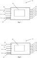
- the control unit 10 comprises a first energy supply connection 12 and a second energy supply connection 14.
- the first energy supply connection can be connected to an energy source, for example a battery of a vehicle, in order to supply the control unit 10 with electrical energy.
- the second energy supply connection 14 is also provided in order to supply the control unit 10 with electrical energy, with an energy source that can be connected to the second energy supply connection preferably being an auxiliary energy source.
- the control unit 10 includes a signal connection 15.
- the signal connection 15 is used to supply control or switching signals.
- control unit includes outputs 16-26.
- Outputs 16-26 are used to electrically control components. These components are, for example, electrical or electromechanical components, such as a valve or a valve component of a valve.
- control unit 10 includes a control unit 28.
- Control unit 28 is used to operate the control unit in a first mode and in a second mode.
- In 1 shows the operation of the controller in the first mode. This is shown as an example by the dashed lines of the second energy supply connection 14, which is expressed by this representation that energy can be consumed by the control device 10 via the first energy supply connection 12, wherein energy via the second energy supply connection 14 is not consumed in this mode.
- energy is therefore supplied from the first energy supply connection 12 was added, with all outputs 16-26, which are assigned to a first number of outputs 16-26, using the energy that can be received via the first power supply connection 12, can be controlled. The control takes place depending on the control unit 28.
- the first energy supply connection 12 has a first contact partner 30 .
- the second power supply connection has a further first contact partner 32 .
- the first contact partner 30 and the further first contact partner 32 do not differ except for the solid line or the dashed line in the illustration. Nevertheless, the first contact partner 30 of the first energy supply connection 12 is designed in such a way that it has a lower line resistance than the further first contact partner 32 of the second energy supply connection 14.
- the first contact partner 30 preferably has a larger cross section than the further first contact partner 32.
- contact partners of the second energy supply connection 14 are preferably designed in the same way as contact partners 34 of the signal connection 15.
- FIG. 2 shows the control unit 10 in the second mode.
- energy can be received via the second energy supply connection 14 in order to supply components. This is shown in turn by broken lines of the contact partners 30 of the first supply connection and solid lines of the contact partners 32 of the second energy supply connection 14 .
- this second mode only a second number of the outputs 16-26, namely the outputs 18 and 22, can now be supplied with energy from the second energy supply connection 14. This in turn is illustrated by the now dashed lines of terminals 16, 20, 24 and 26.
- Activation in the second mode, shown here, with the control unit 28 is therefore limited in such a way that only the outputs 18 and 22 can still be activated are, whereby a maximum power consumption is reduced compared to the first mode and thus ensures that the contact partners 32 of the second power supply connection 14 are not destroyed.
- a standardized control device connector or a standardized control device connector is possible in an embodiment of the same contact partner 32 of the second energy connection and the contact partner 34 of the signal connection 15 .
Landscapes
- Engineering & Computer Science (AREA)
- Mechanical Engineering (AREA)
- General Engineering & Computer Science (AREA)
- Power Engineering (AREA)
- Transportation (AREA)
- Automation & Control Theory (AREA)
- Human Computer Interaction (AREA)
- Valves And Accessory Devices For Braking Systems (AREA)
- Electric Propulsion And Braking For Vehicles (AREA)
- Direct Current Feeding And Distribution (AREA)
Claims (9)
- Appareil de commande électrique (10) pour une remorque ou un véhicule, l'appareil de commande électrique (10) étant un appareil de commande de transmission (TCU, Transmission Control Unit) pour une commande de transmission, comprenant : - une unité de commande (28) de fonctionnement de l'appareil de commande (10), - un premier raccord d'alimentation en énergie (12), - un second raccord d'alimentation en énergie (14) et - plusieurs sorties (16-26) destinées à piloter électriquement, en particulier alimenter électriquement, des composants pouvant être raccordés de manière commandable à l'appareil de commande, qui sont des composants électriques ou électromécaniques, dans lequel l'unité de commande (28) de fonctionnement de l'appareil de commande (10) peut fonctionner dans un premier mode et dans un second mode, un premier nombre des sorties pouvant être pilotées dans le premier mode par l'énergie provenant du premier raccord d'alimentation en énergie et, dans le second mode, un second nombre des sorties pouvant être pilotées par l'énergie provenant du second raccord d'alimentation en énergie, quelques-unes des plusieurs sorties mentionnées n'étant associées qu'au premier nombre, d'autres des plusieurs sorties mentionnées étant associées au premier et au second nombre de telle sorte que les dernières sorties mentionnées peuvent être pilotées par l'énergie dans les deux modes, le second nombre étant en outre inférieur au premier nombre, l'appareil de commande étant conçu pour piloter, à l'aide d'au moins l'une des sorties, un composant qui est une vanne, comprenant un composant de vanne magnétique électrique et/ou un composant de vanne pneumatique ou hydraulique, de préférence une électrovanne.
- Appareil de commande électrique (10) selon la revendication 1, dans lequel au moins un premier partenaire de contact (30) du premier raccord d'alimentation en énergie (12) présente une résistance de ligne inférieure à celle d'un autre premier partenaire de contact (32) du second raccord d'alimentation en énergie (14).
- Appareil de commande électrique (10) selon la revendication 2, dans lequel l'appareil de commande présente au moins un raccord de signal (15) destiné à fournir des signaux de commande, comportant plusieurs partenaires de contact (34), qui présentent respectivement une résistance de ligne sensiblement identique, la résistance de ligne d'au moins un partenaire de contact (34) du raccord de signal (15) et la résistance de ligne au moins de l'autre premier partenaire de contact (32) du second raccord d'alimentation en énergie (14) étant sensiblement identiques.
- Appareil de commande électrique (10) selon la revendication 2 ou 3, dans lequel le premier partenaire de contact (30) du premier raccord d'alimentation en énergie (12) est conçu pour fournir un premier potentiel de tension, de préférence positif, et un autre premier partenaire de contact (32) du second raccord d'alimentation en énergie (14) est conçu pour fournir un deuxième potentiel de tension, de préférence aussi positif.
- Appareil de commande électrique (10) selon l'une des revendications précédentes, dans lequel le premier accord d'alimentation en énergie (12) est conçu pour être connecté à une source d'énergie primaire et/ou le second raccord d'alimentation en énergie (14) est conçu pour être connecté à une source d'énergie auxiliaire.
- Système comportant un appareil de commande électrique selon l'une des revendications 1 à 5 ainsi qu'au moins un composant, qui est un composant électrique ou électromécanique, l'au moins un composant pouvant être connecté électriquement à au moins l'une des sorties (16-26).
- Système selon la revendication 6, comportant une source d'énergie primaire et une source d'énergie auxiliaire, la source d'énergie primaire pouvant être connectée électriquement au premier raccord d'alimentation en énergie (12) et la source d'énergie auxiliaire pouvant être connectée électriquement au second raccord d'alimentation en énergie (14).
- Système selon la revendication 6, dans lequel l'au moins un composant comprend au moins un premier et un deuxième composant, le premier composant étant raccordé, au moins lors du fonctionnement, à une première sortie des sorties (16-26) et le deuxième composant étant raccordé à une deuxième sortie des sorties (16-26), la première et la deuxième sortie étant associées au premier nombre de sorties (16-26) et seule la deuxième sortie parmi la première et la deuxième sortie étant également associée au second nombre de sorties (16-26).
- Procédé de fonctionnement d'une remorque ou d'un véhicule, en particulier d'un véhicule utilitaire, telle qu'un camion ou analogue, ou une voiture particulière, par pilotage de composants électriques ou électromécaniques à l'aide d'un appareil de commande (10) selon l'une des revendications 1 à 5 ou d'un système selon l'une des revendications 6 à 8.
Applications Claiming Priority (1)
| Application Number | Priority Date | Filing Date | Title |
|---|---|---|---|
| DE102018117447.0A DE102018117447A1 (de) | 2018-07-19 | 2018-07-19 | Elektrisches Steuergerät für ein Fahrzeug sowie System damit und Verfahren zum Betreiben eines Fahrzeugs |
Publications (2)
| Publication Number | Publication Date |
|---|---|
| EP3608193A1 EP3608193A1 (fr) | 2020-02-12 |
| EP3608193B1 true EP3608193B1 (fr) | 2023-08-09 |
Family
ID=66867004
Family Applications (1)
| Application Number | Title | Priority Date | Filing Date |
|---|---|---|---|
| EP19180236.2A Active EP3608193B1 (fr) | 2018-07-19 | 2019-06-14 | Appareil de commande électrique pour un véhicule ainsi que système correspondant et procédé de fonctionnement d'un véhicule |
Country Status (3)
| Country | Link |
|---|---|
| EP (1) | EP3608193B1 (fr) |
| CN (1) | CN110733440A (fr) |
| DE (1) | DE102018117447A1 (fr) |
Citations (4)
| Publication number | Priority date | Publication date | Assignee | Title |
|---|---|---|---|---|
| US6390215B1 (en) * | 1998-05-29 | 2002-05-21 | Honda Giken Kogyo Kabushiki Kaisha | Electric vehicle |
| EP2587618A2 (fr) * | 2011-10-27 | 2013-05-01 | Sanyo Electric Co. Ltd | Appareil de source d'alimentation de véhicule et véhicule équipé de l'appareil de source d'alimentation |
| DE102012221570A1 (de) * | 2012-11-26 | 2014-05-28 | Siemens Aktiengesellschaft | Elektrische Schaltungsanordnung für ein elektrisch angetriebenes Fahrzeug, Fahrzeug und entsprechendes Verfahren |
| EP2783904A2 (fr) * | 2013-03-25 | 2014-10-01 | Toyota Jidosha Kabushiki Kaisha | Système de véhicule |
Family Cites Families (10)
| Publication number | Priority date | Publication date | Assignee | Title |
|---|---|---|---|---|
| US4379332A (en) * | 1978-09-25 | 1983-04-05 | The Bendix Corporation | Electronic fuel injection control system for an internal combustion engine |
| DE4424471C2 (de) | 1994-07-12 | 1997-03-20 | Daimler Benz Ag | Elektrisches Anhängeranschlußgerät für ein Zugfahrzeug |
| JPH0886825A (ja) * | 1994-09-19 | 1996-04-02 | Mazda Motor Corp | 自動車の駆動回路制御装置 |
| JP4555136B2 (ja) * | 2005-03-31 | 2010-09-29 | 本田技研工業株式会社 | 燃料電池の電気システム、燃料電池車両及び電力供給方法 |
| US7443048B2 (en) * | 2005-06-30 | 2008-10-28 | Caterpillar Inc. | Method for operating an electrical system |
| WO2009145678A1 (fr) * | 2008-05-26 | 2009-12-03 | Volvo Technology Corporation | Module interrupteur pour un réseau d'alimentation électrique et réseau d'alimentation électrique comprenant au moins un module interrupteur |
| WO2010140253A1 (fr) * | 2009-06-05 | 2010-12-09 | トヨタ自動車株式会社 | Voiture électrique, et procédé d'établissement d'énergie électrique à décharge admissible en entier dans la voiture électrique |
| DE112014003026B4 (de) * | 2013-06-26 | 2024-01-04 | Schaeffler Technologies AG & Co. KG | Steuergerät |
| WO2015039658A1 (fr) | 2013-09-19 | 2015-03-26 | Schaeffler Technologies AG & Co. KG | Procédé permettant d'alimenter un appareil de commande |
| JP6378119B2 (ja) * | 2015-03-16 | 2018-08-22 | 日立建機株式会社 | 制御コントローラ、ステアバイワイヤシステムおよび機械 |
-
2018
- 2018-07-19 DE DE102018117447.0A patent/DE102018117447A1/de not_active Withdrawn
-
2019
- 2019-06-14 EP EP19180236.2A patent/EP3608193B1/fr active Active
- 2019-07-19 CN CN201910654803.1A patent/CN110733440A/zh active Pending
Patent Citations (4)
| Publication number | Priority date | Publication date | Assignee | Title |
|---|---|---|---|---|
| US6390215B1 (en) * | 1998-05-29 | 2002-05-21 | Honda Giken Kogyo Kabushiki Kaisha | Electric vehicle |
| EP2587618A2 (fr) * | 2011-10-27 | 2013-05-01 | Sanyo Electric Co. Ltd | Appareil de source d'alimentation de véhicule et véhicule équipé de l'appareil de source d'alimentation |
| DE102012221570A1 (de) * | 2012-11-26 | 2014-05-28 | Siemens Aktiengesellschaft | Elektrische Schaltungsanordnung für ein elektrisch angetriebenes Fahrzeug, Fahrzeug und entsprechendes Verfahren |
| EP2783904A2 (fr) * | 2013-03-25 | 2014-10-01 | Toyota Jidosha Kabushiki Kaisha | Système de véhicule |
Also Published As
| Publication number | Publication date |
|---|---|
| EP3608193A1 (fr) | 2020-02-12 |
| CN110733440A (zh) | 2020-01-31 |
| DE102018117447A1 (de) | 2020-01-23 |
Similar Documents
| Publication | Publication Date | Title |
|---|---|---|
| DE112010004598B4 (de) | Elektrisch gesteuertes (Shift-By-Wire) Fahrstufenauswahlsystem für ein Schaltgetriebe,zugehöriger Aktuator und Verfahren zum Betätigen | |
| EP1819567B1 (fr) | Système de frein de stationnement éléctromecanique et système éléctronique pour le faire fonctionner | |
| DE19831733A1 (de) | Kraftfahrzeug mit einem elektronisch gesteuerten Automatikgetriebe und einer fremdkraftbetätigten Feststellbremse | |
| DE102012113126B4 (de) | Elektronische Schaltvorrichtung eines Fahrzeugs | |
| EP3661819B1 (fr) | Système de commande pour véhicule automobile, véhicule automobile, procédé de commande d'un véhicule automobile, produit programme informatique et support lisible par ordinateur | |
| DE112014003026B4 (de) | Steuergerät | |
| WO2018087260A1 (fr) | Répartiteur de puissance et réseau de bord comprenant au moins un répartiteur de puissance | |
| EP3741635A1 (fr) | Système de commande de frein | |
| EP1989470B1 (fr) | Concept de sécurité pour un dispositif de positionnement à engrenage | |
| DE102017001409A1 (de) | Verfahren und Fahrzeugsteuergerät für ein autonomes Fahrzeug und Fahrzeug | |
| DE102013101999B4 (de) | Bereichs-Schalteinrichtung | |
| DE102007042210A1 (de) | Verfahren zum automatischen Einlegen einer Parksperre eines automatischen oder automatisierten Getriebes eines Kraftfahrzeugs | |
| DE112011100582B4 (de) | Smart Aktor,Verfahren und Steuerungssystem zur Betätigung einer Kupplung | |
| WO2019224017A1 (fr) | Système de commande pour véhicule automobile, véhicule automobile, procédé de commande d'un véhicule automobile, produit programme informatique et support lisible par ordinateur | |
| DE102008064421B4 (de) | Schlüsselverriegelungssteuersystem und Startvorrichtung, die ein Schlüsselverriegelungssteuersystem aufweist | |
| EP3691940A1 (fr) | Agencement de soupapes et système de freinage | |
| DE102005023818B4 (de) | Anzeigeeinheit für ein elektrifiziertes Schaltgetriebe in einem Fahrzeug | |
| WO2020058030A1 (fr) | Système de frein de stationnement électronique et procédé pour faire fonctionner un système de frein de stationnement électronique | |
| DE102014206925A1 (de) | Kraftfahrzeug-Bordnetz und Verfahren zum Erkennen eines Lichtbogens in einem Kraftfahrzeug-Bordnetz | |
| EP3608193A1 (fr) | Appareil de commande électrique pour un véhicule ainsi que système correspondant et procédé de fonctionnement d'un véhicule | |
| DE102020211902A1 (de) | Vorrichtung für ein automatisches Parkbremssystem | |
| EP2176104B1 (fr) | Commande d'un actionneur de frein de véhicule automobile | |
| DE102013214066A1 (de) | Steuergerät | |
| DE102005019864B4 (de) | Elektrische Lenkungsverriegelung | |
| DE102017106909B4 (de) | Schaltungseinrichtung für ein Bordnetz eines Fahrzeugs sowie Verfahren |
Legal Events
| Date | Code | Title | Description |
|---|---|---|---|
| PUAI | Public reference made under article 153(3) epc to a published international application that has entered the european phase |
Free format text: ORIGINAL CODE: 0009012 |
|
| STAA | Information on the status of an ep patent application or granted ep patent |
Free format text: STATUS: THE APPLICATION HAS BEEN PUBLISHED |
|
| AK | Designated contracting states |
Kind code of ref document: A1 Designated state(s): AL AT BE BG CH CY CZ DE DK EE ES FI FR GB GR HR HU IE IS IT LI LT LU LV MC MK MT NL NO PL PT RO RS SE SI SK SM TR |
|
| AX | Request for extension of the european patent |
Extension state: BA ME |
|
| STAA | Information on the status of an ep patent application or granted ep patent |
Free format text: STATUS: REQUEST FOR EXAMINATION WAS MADE |
|
| 17P | Request for examination filed |
Effective date: 20200812 |
|
| RBV | Designated contracting states (corrected) |
Designated state(s): AL AT BE BG CH CY CZ DE DK EE ES FI FR GB GR HR HU IE IS IT LI LT LU LV MC MK MT NL NO PL PT RO RS SE SI SK SM TR |
|
| RAP3 | Party data changed (applicant data changed or rights of an application transferred) |
Owner name: ZF CV SYSTEMS HANNOVER GMBH |
|
| STAA | Information on the status of an ep patent application or granted ep patent |
Free format text: STATUS: EXAMINATION IS IN PROGRESS |
|
| 17Q | First examination report despatched |
Effective date: 20211104 |
|
| RAP1 | Party data changed (applicant data changed or rights of an application transferred) |
Owner name: ZF CV SYSTEMS EUROPE BV |
|
| RIC1 | Information provided on ipc code assigned before grant |
Ipc: F16H 61/00 20060101ALI20230206BHEP Ipc: B60L 1/00 20060101ALI20230206BHEP Ipc: F16H 61/12 20060101ALI20230206BHEP Ipc: B60W 50/023 20120101AFI20230206BHEP |
|
| GRAP | Despatch of communication of intention to grant a patent |
Free format text: ORIGINAL CODE: EPIDOSNIGR1 |
|
| STAA | Information on the status of an ep patent application or granted ep patent |
Free format text: STATUS: GRANT OF PATENT IS INTENDED |
|
| INTG | Intention to grant announced |
Effective date: 20230417 |
|
| GRAS | Grant fee paid |
Free format text: ORIGINAL CODE: EPIDOSNIGR3 |
|
| GRAA | (expected) grant |
Free format text: ORIGINAL CODE: 0009210 |
|
| STAA | Information on the status of an ep patent application or granted ep patent |
Free format text: STATUS: THE PATENT HAS BEEN GRANTED |
|
| AK | Designated contracting states |
Kind code of ref document: B1 Designated state(s): AL AT BE BG CH CY CZ DE DK EE ES FI FR GB GR HR HU IE IS IT LI LT LU LV MC MK MT NL NO PL PT RO RS SE SI SK SM TR |
|
| REG | Reference to a national code |
Ref country code: GB Ref legal event code: FG4D Free format text: NOT ENGLISH |
|
| REG | Reference to a national code |
Ref country code: CH Ref legal event code: EP |
|
| REG | Reference to a national code |
Ref country code: IE Ref legal event code: FG4D Free format text: LANGUAGE OF EP DOCUMENT: GERMAN |
|
| REG | Reference to a national code |
Ref country code: DE Ref legal event code: R096 Ref document number: 502019008837 Country of ref document: DE |
|
| REG | Reference to a national code |
Ref country code: LT Ref legal event code: MG9D |
|
| REG | Reference to a national code |
Ref country code: NL Ref legal event code: MP Effective date: 20230809 |
|
| PG25 | Lapsed in a contracting state [announced via postgrant information from national office to epo] |
Ref country code: GR Free format text: LAPSE BECAUSE OF FAILURE TO SUBMIT A TRANSLATION OF THE DESCRIPTION OR TO PAY THE FEE WITHIN THE PRESCRIBED TIME-LIMIT Effective date: 20231110 |
|
| PG25 | Lapsed in a contracting state [announced via postgrant information from national office to epo] |
Ref country code: IS Free format text: LAPSE BECAUSE OF FAILURE TO SUBMIT A TRANSLATION OF THE DESCRIPTION OR TO PAY THE FEE WITHIN THE PRESCRIBED TIME-LIMIT Effective date: 20231209 |
|
| PG25 | Lapsed in a contracting state [announced via postgrant information from national office to epo] |
Ref country code: SE Free format text: LAPSE BECAUSE OF FAILURE TO SUBMIT A TRANSLATION OF THE DESCRIPTION OR TO PAY THE FEE WITHIN THE PRESCRIBED TIME-LIMIT Effective date: 20230809 Ref country code: RS Free format text: LAPSE BECAUSE OF FAILURE TO SUBMIT A TRANSLATION OF THE DESCRIPTION OR TO PAY THE FEE WITHIN THE PRESCRIBED TIME-LIMIT Effective date: 20230809 Ref country code: PT Free format text: LAPSE BECAUSE OF FAILURE TO SUBMIT A TRANSLATION OF THE DESCRIPTION OR TO PAY THE FEE WITHIN THE PRESCRIBED TIME-LIMIT Effective date: 20231211 Ref country code: NO Free format text: LAPSE BECAUSE OF FAILURE TO SUBMIT A TRANSLATION OF THE DESCRIPTION OR TO PAY THE FEE WITHIN THE PRESCRIBED TIME-LIMIT Effective date: 20231109 Ref country code: NL Free format text: LAPSE BECAUSE OF FAILURE TO SUBMIT A TRANSLATION OF THE DESCRIPTION OR TO PAY THE FEE WITHIN THE PRESCRIBED TIME-LIMIT Effective date: 20230809 Ref country code: LV Free format text: LAPSE BECAUSE OF FAILURE TO SUBMIT A TRANSLATION OF THE DESCRIPTION OR TO PAY THE FEE WITHIN THE PRESCRIBED TIME-LIMIT Effective date: 20230809 Ref country code: LT Free format text: LAPSE BECAUSE OF FAILURE TO SUBMIT A TRANSLATION OF THE DESCRIPTION OR TO PAY THE FEE WITHIN THE PRESCRIBED TIME-LIMIT Effective date: 20230809 Ref country code: IS Free format text: LAPSE BECAUSE OF FAILURE TO SUBMIT A TRANSLATION OF THE DESCRIPTION OR TO PAY THE FEE WITHIN THE PRESCRIBED TIME-LIMIT Effective date: 20231209 Ref country code: HR Free format text: LAPSE BECAUSE OF FAILURE TO SUBMIT A TRANSLATION OF THE DESCRIPTION OR TO PAY THE FEE WITHIN THE PRESCRIBED TIME-LIMIT Effective date: 20230809 Ref country code: GR Free format text: LAPSE BECAUSE OF FAILURE TO SUBMIT A TRANSLATION OF THE DESCRIPTION OR TO PAY THE FEE WITHIN THE PRESCRIBED TIME-LIMIT Effective date: 20231110 Ref country code: FI Free format text: LAPSE BECAUSE OF FAILURE TO SUBMIT A TRANSLATION OF THE DESCRIPTION OR TO PAY THE FEE WITHIN THE PRESCRIBED TIME-LIMIT Effective date: 20230809 |
|
| PG25 | Lapsed in a contracting state [announced via postgrant information from national office to epo] |
Ref country code: PL Free format text: LAPSE BECAUSE OF FAILURE TO SUBMIT A TRANSLATION OF THE DESCRIPTION OR TO PAY THE FEE WITHIN THE PRESCRIBED TIME-LIMIT Effective date: 20230809 |
|
| PG25 | Lapsed in a contracting state [announced via postgrant information from national office to epo] |
Ref country code: ES Free format text: LAPSE BECAUSE OF FAILURE TO SUBMIT A TRANSLATION OF THE DESCRIPTION OR TO PAY THE FEE WITHIN THE PRESCRIBED TIME-LIMIT Effective date: 20230809 |
|
| PG25 | Lapsed in a contracting state [announced via postgrant information from national office to epo] |
Ref country code: SM Free format text: LAPSE BECAUSE OF FAILURE TO SUBMIT A TRANSLATION OF THE DESCRIPTION OR TO PAY THE FEE WITHIN THE PRESCRIBED TIME-LIMIT Effective date: 20230809 Ref country code: RO Free format text: LAPSE BECAUSE OF FAILURE TO SUBMIT A TRANSLATION OF THE DESCRIPTION OR TO PAY THE FEE WITHIN THE PRESCRIBED TIME-LIMIT Effective date: 20230809 Ref country code: ES Free format text: LAPSE BECAUSE OF FAILURE TO SUBMIT A TRANSLATION OF THE DESCRIPTION OR TO PAY THE FEE WITHIN THE PRESCRIBED TIME-LIMIT Effective date: 20230809 Ref country code: EE Free format text: LAPSE BECAUSE OF FAILURE TO SUBMIT A TRANSLATION OF THE DESCRIPTION OR TO PAY THE FEE WITHIN THE PRESCRIBED TIME-LIMIT Effective date: 20230809 Ref country code: DK Free format text: LAPSE BECAUSE OF FAILURE TO SUBMIT A TRANSLATION OF THE DESCRIPTION OR TO PAY THE FEE WITHIN THE PRESCRIBED TIME-LIMIT Effective date: 20230809 Ref country code: CZ Free format text: LAPSE BECAUSE OF FAILURE TO SUBMIT A TRANSLATION OF THE DESCRIPTION OR TO PAY THE FEE WITHIN THE PRESCRIBED TIME-LIMIT Effective date: 20230809 Ref country code: SK Free format text: LAPSE BECAUSE OF FAILURE TO SUBMIT A TRANSLATION OF THE DESCRIPTION OR TO PAY THE FEE WITHIN THE PRESCRIBED TIME-LIMIT Effective date: 20230809 |
|
| REG | Reference to a national code |
Ref country code: DE Ref legal event code: R097 Ref document number: 502019008837 Country of ref document: DE |
|
| PG25 | Lapsed in a contracting state [announced via postgrant information from national office to epo] |
Ref country code: IT Free format text: LAPSE BECAUSE OF FAILURE TO SUBMIT A TRANSLATION OF THE DESCRIPTION OR TO PAY THE FEE WITHIN THE PRESCRIBED TIME-LIMIT Effective date: 20230809 |
|
| PLBE | No opposition filed within time limit |
Free format text: ORIGINAL CODE: 0009261 |
|
| STAA | Information on the status of an ep patent application or granted ep patent |
Free format text: STATUS: NO OPPOSITION FILED WITHIN TIME LIMIT |
|
| PGFP | Annual fee paid to national office [announced via postgrant information from national office to epo] |
Ref country code: GB Payment date: 20240402 Year of fee payment: 6 |
|
| 26N | No opposition filed |
Effective date: 20240513 |
|
| PG25 | Lapsed in a contracting state [announced via postgrant information from national office to epo] |
Ref country code: SI Free format text: LAPSE BECAUSE OF FAILURE TO SUBMIT A TRANSLATION OF THE DESCRIPTION OR TO PAY THE FEE WITHIN THE PRESCRIBED TIME-LIMIT Effective date: 20230809 |
|
| PGFP | Annual fee paid to national office [announced via postgrant information from national office to epo] |
Ref country code: FR Payment date: 20240408 Year of fee payment: 6 |
|
| PG25 | Lapsed in a contracting state [announced via postgrant information from national office to epo] |
Ref country code: BG Free format text: LAPSE BECAUSE OF FAILURE TO SUBMIT A TRANSLATION OF THE DESCRIPTION OR TO PAY THE FEE WITHIN THE PRESCRIBED TIME-LIMIT Effective date: 20230809 |
|
| PG25 | Lapsed in a contracting state [announced via postgrant information from national office to epo] |
Ref country code: BG Free format text: LAPSE BECAUSE OF FAILURE TO SUBMIT A TRANSLATION OF THE DESCRIPTION OR TO PAY THE FEE WITHIN THE PRESCRIBED TIME-LIMIT Effective date: 20230809 |
|
| PG25 | Lapsed in a contracting state [announced via postgrant information from national office to epo] |
Ref country code: MC Free format text: LAPSE BECAUSE OF FAILURE TO SUBMIT A TRANSLATION OF THE DESCRIPTION OR TO PAY THE FEE WITHIN THE PRESCRIBED TIME-LIMIT Effective date: 20230809 |
|
| REG | Reference to a national code |
Ref country code: CH Ref legal event code: PL |
|
| PG25 | Lapsed in a contracting state [announced via postgrant information from national office to epo] |
Ref country code: LU Free format text: LAPSE BECAUSE OF NON-PAYMENT OF DUE FEES Effective date: 20240614 |
|
| PG25 | Lapsed in a contracting state [announced via postgrant information from national office to epo] |
Ref country code: IE Free format text: LAPSE BECAUSE OF NON-PAYMENT OF DUE FEES Effective date: 20240614 |
|
| PG25 | Lapsed in a contracting state [announced via postgrant information from national office to epo] |
Ref country code: BE Free format text: LAPSE BECAUSE OF NON-PAYMENT OF DUE FEES Effective date: 20240630 Ref country code: CH Free format text: LAPSE BECAUSE OF NON-PAYMENT OF DUE FEES Effective date: 20240630 |
|
| REG | Reference to a national code |
Ref country code: BE Ref legal event code: MM Effective date: 20240630 |
|
| PGFP | Annual fee paid to national office [announced via postgrant information from national office to epo] |
Ref country code: DE Payment date: 20250402 Year of fee payment: 7 |
|
| REG | Reference to a national code |
Ref country code: AT Ref legal event code: MM01 Ref document number: 1597194 Country of ref document: AT Kind code of ref document: T Effective date: 20240614 |
|
| PG25 | Lapsed in a contracting state [announced via postgrant information from national office to epo] |
Ref country code: AT Free format text: LAPSE BECAUSE OF NON-PAYMENT OF DUE FEES Effective date: 20240614 |
|
| PG25 | Lapsed in a contracting state [announced via postgrant information from national office to epo] |
Ref country code: CY Free format text: LAPSE BECAUSE OF FAILURE TO SUBMIT A TRANSLATION OF THE DESCRIPTION OR TO PAY THE FEE WITHIN THE PRESCRIBED TIME-LIMIT; INVALID AB INITIO Effective date: 20190614 |
|
| GBPC | Gb: european patent ceased through non-payment of renewal fee |
Effective date: 20250614 |
|
| PG25 | Lapsed in a contracting state [announced via postgrant information from national office to epo] |
Ref country code: HU Free format text: LAPSE BECAUSE OF FAILURE TO SUBMIT A TRANSLATION OF THE DESCRIPTION OR TO PAY THE FEE WITHIN THE PRESCRIBED TIME-LIMIT; INVALID AB INITIO Effective date: 20190614 |
|
| PG25 | Lapsed in a contracting state [announced via postgrant information from national office to epo] |
Ref country code: GB Free format text: LAPSE BECAUSE OF NON-PAYMENT OF DUE FEES Effective date: 20250614 |
|
| PG25 | Lapsed in a contracting state [announced via postgrant information from national office to epo] |
Ref country code: FR Free format text: LAPSE BECAUSE OF NON-PAYMENT OF DUE FEES Effective date: 20250630 |