EP3608460B1 - Dispositif de freinage de trame pour fournisseurs de fil d'accumulateur - Google Patents
Dispositif de freinage de trame pour fournisseurs de fil d'accumulateur Download PDFInfo
- Publication number
- EP3608460B1 EP3608460B1 EP19186485.9A EP19186485A EP3608460B1 EP 3608460 B1 EP3608460 B1 EP 3608460B1 EP 19186485 A EP19186485 A EP 19186485A EP 3608460 B1 EP3608460 B1 EP 3608460B1
- Authority
- EP
- European Patent Office
- Prior art keywords
- braking device
- threaded element
- support
- knob
- weft
- Prior art date
- Legal status (The legal status is an assumption and is not a legal conclusion. Google has not performed a legal analysis and makes no representation as to the accuracy of the status listed.)
- Active
Links
Images


Classifications
-
- B—PERFORMING OPERATIONS; TRANSPORTING
- B65—CONVEYING; PACKING; STORING; HANDLING THIN OR FILAMENTARY MATERIAL
- B65H—HANDLING THIN OR FILAMENTARY MATERIAL, e.g. SHEETS, WEBS, CABLES
- B65H59/00—Adjusting or controlling tension in filamentary material, e.g. for preventing snarling; Applications of tension indicators
- B65H59/10—Adjusting or controlling tension in filamentary material, e.g. for preventing snarling; Applications of tension indicators by devices acting on running material and not associated with supply or take-up devices
- B65H59/20—Co-operating surfaces mounted for relative movement
- B65H59/22—Co-operating surfaces mounted for relative movement and arranged to apply pressure to material
-
- D—TEXTILES; PAPER
- D03—WEAVING
- D03D—WOVEN FABRICS; METHODS OF WEAVING; LOOMS
- D03D47/00—Looms in which bulk supply of weft does not pass through shed, e.g. shuttleless looms, gripper shuttle looms, dummy shuttle looms
- D03D47/34—Handling the weft between bulk storage and weft-inserting means
- D03D47/36—Measuring and cutting the weft
- D03D47/361—Drum-type weft feeding devices
- D03D47/364—Yarn braking means acting on the drum
- D03D47/366—Conical
-
- B—PERFORMING OPERATIONS; TRANSPORTING
- B65—CONVEYING; PACKING; STORING; HANDLING THIN OR FILAMENTARY MATERIAL
- B65H—HANDLING THIN OR FILAMENTARY MATERIAL, e.g. SHEETS, WEBS, CABLES
- B65H2701/00—Handled material; Storage means
- B65H2701/30—Handled filamentary material
- B65H2701/31—Textiles threads or artificial strands of filaments
Definitions
- the present invention relates to a weft braking device for accumulator yarn feeders.
- a generic accumulator yarn feeder can comprise a drum that supports, wound thereon, a yarn that is adapted to be unwound on demand by a generic textile machine arranged downstream. Before entering the textile machine, the yarn being unwound from the drum passes through a weft braking device which controls the mechanical tension thereof.
- the weft braking device can be constituted by a hollow frustum-shaped body which is pushed elastically against the delivery end of the drum by a radial system of springs.
- the springs have their inner ends anchored to the smaller base of the frustum-shaped body, and their outer ends anchored to an annular support.
- the latter can move axially on command by a screw/spindle nut mechanism which is incorporated in a fixed arm that extends parallel to the drum.
- the screw/spindle nut mechanism can be actuated manually by way of a knob arranged at the end of the arm, or automatically by a feedback-controlled motor.
- the yarn in output from the feeder slides pressed between the drum and the hollow frustum-shaped body, in so doing receiving a braking action by friction which can be adjusted either manually, by way of the knob, or automatically by the motor.
- a further disadvantage of the conventional system mentioned above is that the adjustment axis, being offset with respect to the axis of translation of the annular support, causes an increase of the amounts of play, as well as oscillations of the annular support about its point of attachment.
- Another known braking device, described in EP 2065496 has a system for adjusting the braking force which is arranged coaxially with respect to the drum. However, it is based on the magnetic repulsion between a first annular magnet fixed coaxially to the hollow frustum-shaped body and a second annular magnet which can be translated axially on command by a knob by way of threaded coupling. Therefore, the system described in EP 2065496 is not applicable to adjustable braking devices based on elastic forces, like the one described previously.
- the aim of the present invention is to provide a weft braking device for accumulator yarn feeders that, although being based on elastic forces, overcomes the drawbacks of the conventional systems described above, and in particular that has more precise operation in relation to the amounts of play in the adjustment mechanism and to the arrangement of the adjustment system.
- an object of the invention is to provide a weft braking device that is relatively simple from the point of view of construction in order to limit manufacturing costs.
- an accumulator yarn feeder 10 comprises a drum 12 which is adapted to support, wound thereon, a yarn Y (shown only in Figure 3 ).
- the yarn is unwound from the drum 12 on demand by a generic textile machine arranged downstream (not shown), after having passed through a weft braking device 14 which will be described in more detail hereinafter.
- a flywheel 16 entrained in rotation by a motor M winds on new loops, taking the yarn from a distaff arranged upstream (not shown).
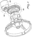
- the weft braking device 14 is supported at the free end of an arm 18 that protrudes from the motor body parallel to the drum 12.
- the weft braking device 14 comprises a hollow braking member 20, typically a thin-walled frustum-shaped body, e.g. made of plastic material, which is pushed elastically with its inner surface against the delivery end 12a ( Figure 3 ) of the drum 12.
- the hollow braking member 20 is supported coaxially to the drum 12 by means of a radial system of traction springs 22.
- the traction springs 22 have their inner ends anchored to a ring 24 which is fixed to the smaller base of the hollow frustum-shaped body 20, and their outer ends anchored to a frame 26 with a circular profile.
- the frame 26 is provided with an outer ring 26a, to which the outer ends of the traction springs 26 are connected, and with an inner ring 26b which is connected to the outer ring 26a by way of a triplet of radial arms 26c.
- the frame 26 is functionally connected to a braking adjustment mechanism 28.
- the braking adjustment mechanism 28 is of the type with screw/spindle nut and comprises a first threaded element 30, which in the embodiment described herein is a spindle nut 30, which is connected to the hollow braking member 20 and can be translated axially at the command of a second threaded element, which in the embodiment described herein is a screw 32.
- the braking adjustment mechanism 28 is mounted on a support 34 which is screwed to the arm 18 and, according to the invention, is provided with elastic means which are functionally interposed between the spindle nut 30 and the support 34 in order to bias the threading of the spindle nut 30 to always engage the threading of the screw 32 on a same side, regardless of the direction of rotation of the screw 32.
- the braking adjustment mechanism 28 is supported coaxially to the drum 12, and the screw 32 is hollow so as to be passed through by the yarn Y that is unwound from the drum 12 ( Figure 3 ).
- the elastic means are arranged so as to act in contrast with the radial system of springs 22, i.e., so as to "press" the spindle nut 32 in the direction of the drum 12, and therefore they have a greater rigidity in an axial direction than that of the radial system of springs 22.
- the elastic means comprise a compression spring 38 which is functionally interposed between the spindle nut 30 and a wall 40 of the support 34 which is perpendicular to the axis of the screw 32 and passed through slideably by the latter.
- the spindle nut 30 is provided with radial pins 42 which slideably engage respective longitudinal grooves 44 which are provided on the support 34 ( Figure 3 ), so as to translate axially without rotation when the screw 32 is rotated.
- the support 34 is covered by a transparent shell 46 which makes it possible to see the position of the radial protrusions 42, which shows the level of braking.
- the spindle nut 30 is connected to the frame 26 by way of a triplet of longitudinal columns 48 which protrude monolithically from the spindle nut 30, pass through respective holes 50 provided on the transparent shell 46, and are screwed axially to the inner ring 26b of the frame 26.
- the screw 32 can be actuated manually by way of a knob 52 which is connected thereto.
- the knob 52 is fixed to the screw 32 on the opposite side of the wall 40 with respect to the spring 38, and is kept pressed by the latter against the wall 40.
- Centering means are interposed between the end wall 40 and the knob 52.
- the centering means comprise a frustum-shaped seat 54, which in the embodiment described herein is provided on the inner axial side of the knob 52, and a frustum-shaped protrusion 56, which in the embodiment described herein is provided on the outer face of the wall 40 and engages the frustum-shaped seat 54.
- the knob 52 can advantageously move by steps between different preset braking positions, which are determined by the snap engagement of protrusions 58, which in this embodiment are spherical and are provided on the outer face of the wall 40, with corresponding seats 60 of the knob 52, which in this embodiment are provided on the face that delimits the inner axial side of the knob 52.
- the yarn Y being unwound from the feeder slides between the delivery end 12a of the drum 12 and the hollow frustum-shaped body 20, receiving from these a braking action owing to friction; then it passes through the screw 32; and finally it is transferred to the textile machine arranged downstream.
- the braking force can be adjusted by the knob 52.
- the threading of the spindle nut 30 always engages the threading of the screw 32 on the same side, regardless of the direction of rotation of the screw 32, so as to eliminate the play when the rotation of the knob 52 is inverted, e.g., in order to reduce the braking force after being increased in an earlier step.
- the solution according to the invention is simple in terms of construction by virtue of the fact that the compression spring 38 performs multiple functions, in addition to the basic function described above.
- it ensures the centering between the knob 52 and the support 34 by way of the frustum-shaped coupling 54, 56, it determines the rotation by steps of the knob 52, and it enables the rapid disengagement of the brake for cleaning/maintenance operations and/or substitution of the braking body.
- the coaxial arrangement of the adjustment mechanism 28 with respect to the drum 12 makes it possible to further reduce the amounts of play and the oscillations of the frame 26, with further benefits in terms of precision of adjustment.
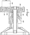
- Figures 4 and 5 show an alternative embodiment of the invention, which differs from the previous one in that the adjustment mechanism 128, instead of being actuated manually by a knob, is actuated by a motor 160 through a geared transmission.
- This transmission is composed of a pinion 162 which is keyed on the driving shaft 164 of the motor 160, and engages a gear 166 which is keyed on the screw 132 of the adjustment mechanism 128.
- the motor 160 is a stepper motor, and is feedback-controlled on the basis of to the signal received from a load cell (not shown) in order to stabilize the yarn tension at a preset value.
- the spring acts in contrast with the radial system of springs that support the hollow frustum-shaped body, so as to also perform the accessory functions described above, it could also be arranged so as to act in the same direction as the radial system of springs, so as to bias the threading of the spindle nut to engage the threading of the screw on the opposite side from the embodiments described.
- the frustum-shaped braking body in the embodiments described can be substituted by a different hollow braking member that extends around an axis, e.g., an annular brush and the like.
- the radial system of springs 22 can also be substituted by other elastically yielding supporting means, e.g., elastic cables and the like.
- the threaded element that is rotated is the screw and the threaded element that performs a translational motion is the spindle nut
- such configuration could be inverted, with the screw being connected to the hollow braking element and made to translate without rotation with respect to the support, and the spindle nut being held axially and made to rotate in order to adjust the braking force.
Landscapes
- Engineering & Computer Science (AREA)
- Textile Engineering (AREA)
- Looms (AREA)
- Unwinding Of Filamentary Materials (AREA)
Claims (10)
- Dispositif de freinage de trame pour des délivreurs à accumulation de fil qui sont pourvus d'un tambour (12) adapté pour supporter un fil (Y) enroulé sur celui-ci qui est adapté pour être déroulé sur demande par une machine à textile, qui comporte un support (34) adapté pour être fixé au délivreur de fil (10), un élément de freinage creux (20) s'étendant autour d'un axe et adapté pour engager coaxialement une extrémité de distribution (12a) dudit tambour (12), et un mécanisme de réglage de freinage (28) qui comporte un premier élément fileté (30) relié audit élément de freinage creux (20) et pouvant se déplacer axialement en translation par rapport au support (34) sur l'ordre d'un second élément fileté (32) qui est supporté en rotation par le support (34), caractérisé en ce qu'il comporte des moyens élastiques (38) qui sont fonctionnellement intercalés entre ledit premier élément fileté (30) et ledit support (34) afin de rappeler le filetage dudit premier élément fileté (30) pour venir en prise avec le filetage dudit second élément fileté (32) toujours d'un même côté quel que soit le sens de rotation dudit second élément fileté (32).
- Dispositif de freinage de trame selon la revendication 1, caractérisé en ce que le premier élément fileté (30) et ledit second élément fileté (32) sont supportés coaxialement au tambour (12).
- Dispositif de freinage de trame selon la revendication 1 ou 2, caractérisé en ce que lesdits moyens élastiques (38) sont agencés de manière à agir contre des moyens de support (22) faisant élastiquement ressort qui sont fonctionnellement intercalés entre ledit élément de freinage creux (20) et ledit premier élément fileté (30), et ont une rigidité plus élevée dans une direction axiale que celle desdits moyens de support (22) faisant élastiquement ressort.
- Dispositif de freinage de trame selon l'une des revendications 1 à 3, caractérisé en ce que ledit premier élément fileté est un écrou de broche (30) qui est guidé pour glisser axialement sans rotation par rapport audit support (34), et ledit second élément fileté est une vis (32).
- Dispositif de freinage de trame selon la revendication 4, caractérisé en ce que ladite vis (32) peut être actionnée manuellement au moyen d'un bouton (52) qui est relié à celle-ci.
- Dispositif de freinage de trame selon la revendication 5, caractérisé en ce que lesdits moyens élastiques (38) sont agencés de manière à pousser axialement ledit bouton (52) contre une paroi (40) dudit support, des moyens de centrage (54, 56) étant intercalés entre ladite paroi (40) et ledit bouton (52).
- Dispositif de freinage de trame selon la revendication 6, caractérisé en ce que lesdits moyens de centrage comportent un logement tronconique (54) qui est agencé sur ledit bouton (52) ou ladite paroi (40) et vient coaxialement en prise avec une saillie tronconique (56) agencée sur l'autre élément parmi ledit bouton (52) ou ladite paroi (40).
- Dispositif de freinage de trame selon l'une des revendications 5 à 7, caractérisé en ce que ledit bouton (52) peut se déplacer par pas entre différentes positions de freinage préréglées déterminées par une prise par encliquetage de saillies (58) agencées sur ledit bouton (52) ou ledit support (34), avec des logements (60) correspondants agencés sur l'autre élément parmi ledit bouton (52) ou ledit support (34).
- Dispositif de freinage de trame selon l'une des revendications 1 à 4, caractérisé en ce que ledit second élément fileté (32) est entraîné par un moteur (160) qui est commandé par asservissement sur la base d'un signal reçu d'une cellule de charge, afin de stabiliser la tension du fil à une valeur préréglée.
- Dispositif de freinage de trame selon l'une des revendications 1 à 9, caractérisé en ce que ledit support (34) est protégé par une coque transparente (46).
Applications Claiming Priority (1)
| Application Number | Priority Date | Filing Date | Title |
|---|---|---|---|
| IT102018000007866A IT201800007866A1 (it) | 2018-08-06 | 2018-08-06 | Dispositivo frena-trama per alimentatori di filato ad accumulo |
Publications (2)
| Publication Number | Publication Date |
|---|---|
| EP3608460A1 EP3608460A1 (fr) | 2020-02-12 |
| EP3608460B1 true EP3608460B1 (fr) | 2020-12-16 |
Family
ID=63965914
Family Applications (1)
| Application Number | Title | Priority Date | Filing Date |
|---|---|---|---|
| EP19186485.9A Active EP3608460B1 (fr) | 2018-08-06 | 2019-07-16 | Dispositif de freinage de trame pour fournisseurs de fil d'accumulateur |
Country Status (3)
| Country | Link |
|---|---|
| EP (1) | EP3608460B1 (fr) |
| CN (1) | CN110803582B (fr) |
| IT (1) | IT201800007866A1 (fr) |
Cited By (1)
| Publication number | Priority date | Publication date | Assignee | Title |
|---|---|---|---|---|
| IT202100031934A1 (it) | 2021-12-21 | 2023-06-21 | Lgl Electronics Spa | Metodo di gestione dei dati operativi in un apparato tessile provvisto di una molteplicità di alimentatori di filato |
Families Citing this family (1)
| Publication number | Priority date | Publication date | Assignee | Title |
|---|---|---|---|---|
| DE102021115596B3 (de) * | 2021-06-16 | 2022-05-12 | Memminger-IRO Gesellschaft mit beschränkter Haftung | Fadenliefergerät |
Family Cites Families (11)
| Publication number | Priority date | Publication date | Assignee | Title |
|---|---|---|---|---|
| DE4007131C2 (de) * | 1990-03-07 | 1999-12-30 | Iro Patent Ag Baar | Liefervorrichtung für laufende Fäden |
| DE19533310A1 (de) * | 1995-07-24 | 1997-01-30 | Iro Ab | Fadenliefergerät |
| DE19743573A1 (de) * | 1997-10-02 | 1999-04-15 | Memminger Iro Gmbh | Fadenbremse |
| IT1311453B1 (it) * | 1999-11-19 | 2002-03-12 | Lgl Electronics Spa | Freno di trama compensatore perfezionato. |
| ITTO20020023U1 (it) * | 2002-02-01 | 2003-08-01 | Lgl Electronics Spa | ,,dispositivo di ritegno del supporto portafreno in dispositivi alimentatori di trama,, |
| DE102006001125A1 (de) * | 2006-01-09 | 2007-07-12 | Iro Ab | Fadenliefergerät und Bremskörper |
| JP2009133018A (ja) | 2007-11-29 | 2009-06-18 | Tmt Machinery Inc | 多糸条用交絡装置 |
| DE602007007101D1 (de) * | 2007-11-30 | 2010-07-22 | Memminger Iro Gmbh | Fadenzuführungsvorrichtung und Fadenbremse |
| ITTO20111217A1 (it) * | 2011-12-28 | 2013-06-29 | Lgl Electronics Spa | Dispositivo frena-trama per alimentatori di filato a tamburo fisso |
| DE102013113122B4 (de) * | 2013-11-27 | 2016-03-03 | Memminger-Iro Gmbh | Fadenliefergerät |
| DE102016117506B3 (de) * | 2016-09-16 | 2017-11-23 | Memminger-Iro Gmbh | Fadenliefergerät |
-
2018
- 2018-08-06 IT IT102018000007866A patent/IT201800007866A1/it unknown
-
2019
- 2019-07-16 EP EP19186485.9A patent/EP3608460B1/fr active Active
- 2019-08-01 CN CN201910707227.2A patent/CN110803582B/zh active Active
Non-Patent Citations (1)
| Title |
|---|
| None * |
Cited By (1)
| Publication number | Priority date | Publication date | Assignee | Title |
|---|---|---|---|---|
| IT202100031934A1 (it) | 2021-12-21 | 2023-06-21 | Lgl Electronics Spa | Metodo di gestione dei dati operativi in un apparato tessile provvisto di una molteplicità di alimentatori di filato |
Also Published As
| Publication number | Publication date |
|---|---|
| EP3608460A1 (fr) | 2020-02-12 |
| CN110803582B (zh) | 2022-06-07 |
| IT201800007866A1 (it) | 2020-02-06 |
| CN110803582A (zh) | 2020-02-18 |
Similar Documents
| Publication | Publication Date | Title |
|---|---|---|
| EP3608460A1 (fr) | Dispositif de freinage de trame pour fournisseurs de fil d'accumulateur | |
| EP2924156B1 (fr) | Dispositif de freinage de fil pour dispositifs d'alimentation en fil de stockage | |
| EP1984596A1 (fr) | Mécanisme d'un dispositif de relevage automatique d'un store à rouleau | |
| US4601439A (en) | Magnetic brake for a fishing reel | |
| EP2065496B1 (fr) | Dispositif d'alimentation en fil et frein de fil | |
| JPS59182167A (ja) | マグネツトテンシヨン装置 | |
| CN110550497B (zh) | 带有机动纱线缠绕卷轴和重绕系统的纱线供给器 | |
| EP2829647A1 (fr) | Dispositif d'alimentation en fil pourvu d'un tambour à canetage et avec dispositif double face commandé par rétroaction | |
| US20130168480A1 (en) | Yarn feeder provided with a stationary drum and with a controlled, weft-braking device | |
| EP0699790B1 (fr) | Organe de retenue de fil pour fournisseur de trame de métier à jet d'air | |
| EP3945150A1 (fr) | Dispositif d'alimentation de fil d'accumulation muni d'un dispositif d'espacement pour séparer les boucles de fil enroulées sur le tambour | |
| EP3392384B1 (fr) | Dispositif de freinage de trame pour fournisseurs de fil d'accumulateur et fournisseur faisant appel à un tel dispositif de freinage de trame | |
| JP2018528334A (ja) | 制動機構を備える貯蔵紡糸供給機及び交換可能部材 | |
| CN108884610B (zh) | 具有用于纱线张力调节的电动机组件的喂纱器 | |
| EP1334941B1 (fr) | Dispositif pour retenir le support de frein dans les fournisseurs de trame | |
| EP1053966B1 (fr) | Dispositif de retenue libérable pour le support de frein dans les fournisseurs de trame pour machines textiles | |
| EP2853626B1 (fr) | Dispositif d'alimentation de fil avec tambour de stockage | |
| EP1624098B1 (fr) | Fournisseur de trame pour métiers à tisser avec un frein de fil à ajustage automatique | |
| JPH0369824B2 (fr) | ||
| EP3521493B1 (fr) | Dispositif d'alimentation de fil avec dispositif de freinage de trame commandé par rétroaction | |
| BE1025536B1 (nl) | Draadreminrichting voor een inslagtoevoerinrichting | |
| EP0547712A2 (fr) | Porte bobine suspendu rotativement avec force de freinage ajustable et arrêtable | |
| SU1392017A1 (ru) | Устройство дл регулировани нат жени нити при намотке | |
| EP0867390B1 (fr) | Dispositifs de freinage de fil autoréglables pour fournisseurs de fil | |
| EP0405382A1 (fr) | Dispositif d'alimentation de fil de trame avec tambour comme dévidoir pour machines de tissage à jet |
Legal Events
| Date | Code | Title | Description |
|---|---|---|---|
| PUAI | Public reference made under article 153(3) epc to a published international application that has entered the european phase |
Free format text: ORIGINAL CODE: 0009012 |
|
| STAA | Information on the status of an ep patent application or granted ep patent |
Free format text: STATUS: THE APPLICATION HAS BEEN PUBLISHED |
|
| AK | Designated contracting states |
Kind code of ref document: A1 Designated state(s): AL AT BE BG CH CY CZ DE DK EE ES FI FR GB GR HR HU IE IS IT LI LT LU LV MC MK MT NL NO PL PT RO RS SE SI SK SM TR |
|
| AX | Request for extension of the european patent |
Extension state: BA ME |
|
| STAA | Information on the status of an ep patent application or granted ep patent |
Free format text: STATUS: REQUEST FOR EXAMINATION WAS MADE |
|
| 17P | Request for examination filed |
Effective date: 20200304 |
|
| RBV | Designated contracting states (corrected) |
Designated state(s): AL AT BE BG CH CY CZ DE DK EE ES FI FR GB GR HR HU IE IS IT LI LT LU LV MC MK MT NL NO PL PT RO RS SE SI SK SM TR |
|
| GRAP | Despatch of communication of intention to grant a patent |
Free format text: ORIGINAL CODE: EPIDOSNIGR1 |
|
| STAA | Information on the status of an ep patent application or granted ep patent |
Free format text: STATUS: GRANT OF PATENT IS INTENDED |
|
| INTG | Intention to grant announced |
Effective date: 20200708 |
|
| GRAS | Grant fee paid |
Free format text: ORIGINAL CODE: EPIDOSNIGR3 |
|
| GRAA | (expected) grant |
Free format text: ORIGINAL CODE: 0009210 |
|
| STAA | Information on the status of an ep patent application or granted ep patent |
Free format text: STATUS: THE PATENT HAS BEEN GRANTED |
|
| AK | Designated contracting states |
Kind code of ref document: B1 Designated state(s): AL AT BE BG CH CY CZ DE DK EE ES FI FR GB GR HR HU IE IS IT LI LT LU LV MC MK MT NL NO PL PT RO RS SE SI SK SM TR |
|
| REG | Reference to a national code |
Ref country code: GB Ref legal event code: FG4D |
|
| REG | Reference to a national code |
Ref country code: DE Ref legal event code: R096 Ref document number: 602019001769 Country of ref document: DE |
|
| REG | Reference to a national code |
Ref country code: IE Ref legal event code: FG4D |
|
| REG | Reference to a national code |
Ref country code: AT Ref legal event code: REF Ref document number: 1345700 Country of ref document: AT Kind code of ref document: T Effective date: 20210115 |
|
| PG25 | Lapsed in a contracting state [announced via postgrant information from national office to epo] |
Ref country code: RS Free format text: LAPSE BECAUSE OF FAILURE TO SUBMIT A TRANSLATION OF THE DESCRIPTION OR TO PAY THE FEE WITHIN THE PRESCRIBED TIME-LIMIT Effective date: 20201216 Ref country code: FI Free format text: LAPSE BECAUSE OF FAILURE TO SUBMIT A TRANSLATION OF THE DESCRIPTION OR TO PAY THE FEE WITHIN THE PRESCRIBED TIME-LIMIT Effective date: 20201216 Ref country code: NO Free format text: LAPSE BECAUSE OF FAILURE TO SUBMIT A TRANSLATION OF THE DESCRIPTION OR TO PAY THE FEE WITHIN THE PRESCRIBED TIME-LIMIT Effective date: 20210316 Ref country code: GR Free format text: LAPSE BECAUSE OF FAILURE TO SUBMIT A TRANSLATION OF THE DESCRIPTION OR TO PAY THE FEE WITHIN THE PRESCRIBED TIME-LIMIT Effective date: 20210317 |
|
| REG | Reference to a national code |
Ref country code: AT Ref legal event code: MK05 Ref document number: 1345700 Country of ref document: AT Kind code of ref document: T Effective date: 20201216 |
|
| REG | Reference to a national code |
Ref country code: NL Ref legal event code: MP Effective date: 20201216 |
|
| PG25 | Lapsed in a contracting state [announced via postgrant information from national office to epo] |
Ref country code: BG Free format text: LAPSE BECAUSE OF FAILURE TO SUBMIT A TRANSLATION OF THE DESCRIPTION OR TO PAY THE FEE WITHIN THE PRESCRIBED TIME-LIMIT Effective date: 20210316 Ref country code: LV Free format text: LAPSE BECAUSE OF FAILURE TO SUBMIT A TRANSLATION OF THE DESCRIPTION OR TO PAY THE FEE WITHIN THE PRESCRIBED TIME-LIMIT Effective date: 20201216 Ref country code: SE Free format text: LAPSE BECAUSE OF FAILURE TO SUBMIT A TRANSLATION OF THE DESCRIPTION OR TO PAY THE FEE WITHIN THE PRESCRIBED TIME-LIMIT Effective date: 20201216 |
|
| PG25 | Lapsed in a contracting state [announced via postgrant information from national office to epo] |
Ref country code: HR Free format text: LAPSE BECAUSE OF FAILURE TO SUBMIT A TRANSLATION OF THE DESCRIPTION OR TO PAY THE FEE WITHIN THE PRESCRIBED TIME-LIMIT Effective date: 20201216 Ref country code: NL Free format text: LAPSE BECAUSE OF FAILURE TO SUBMIT A TRANSLATION OF THE DESCRIPTION OR TO PAY THE FEE WITHIN THE PRESCRIBED TIME-LIMIT Effective date: 20201216 |
|
| REG | Reference to a national code |
Ref country code: LT Ref legal event code: MG9D |
|
| PG25 | Lapsed in a contracting state [announced via postgrant information from national office to epo] |
Ref country code: LT Free format text: LAPSE BECAUSE OF FAILURE TO SUBMIT A TRANSLATION OF THE DESCRIPTION OR TO PAY THE FEE WITHIN THE PRESCRIBED TIME-LIMIT Effective date: 20201216 Ref country code: PT Free format text: LAPSE BECAUSE OF FAILURE TO SUBMIT A TRANSLATION OF THE DESCRIPTION OR TO PAY THE FEE WITHIN THE PRESCRIBED TIME-LIMIT Effective date: 20210416 Ref country code: RO Free format text: LAPSE BECAUSE OF FAILURE TO SUBMIT A TRANSLATION OF THE DESCRIPTION OR TO PAY THE FEE WITHIN THE PRESCRIBED TIME-LIMIT Effective date: 20201216 Ref country code: EE Free format text: LAPSE BECAUSE OF FAILURE TO SUBMIT A TRANSLATION OF THE DESCRIPTION OR TO PAY THE FEE WITHIN THE PRESCRIBED TIME-LIMIT Effective date: 20201216 Ref country code: SK Free format text: LAPSE BECAUSE OF FAILURE TO SUBMIT A TRANSLATION OF THE DESCRIPTION OR TO PAY THE FEE WITHIN THE PRESCRIBED TIME-LIMIT Effective date: 20201216 Ref country code: SM Free format text: LAPSE BECAUSE OF FAILURE TO SUBMIT A TRANSLATION OF THE DESCRIPTION OR TO PAY THE FEE WITHIN THE PRESCRIBED TIME-LIMIT Effective date: 20201216 Ref country code: CZ Free format text: LAPSE BECAUSE OF FAILURE TO SUBMIT A TRANSLATION OF THE DESCRIPTION OR TO PAY THE FEE WITHIN THE PRESCRIBED TIME-LIMIT Effective date: 20201216 |
|
| PG25 | Lapsed in a contracting state [announced via postgrant information from national office to epo] |
Ref country code: PL Free format text: LAPSE BECAUSE OF FAILURE TO SUBMIT A TRANSLATION OF THE DESCRIPTION OR TO PAY THE FEE WITHIN THE PRESCRIBED TIME-LIMIT Effective date: 20201216 Ref country code: AT Free format text: LAPSE BECAUSE OF FAILURE TO SUBMIT A TRANSLATION OF THE DESCRIPTION OR TO PAY THE FEE WITHIN THE PRESCRIBED TIME-LIMIT Effective date: 20201216 |
|
| REG | Reference to a national code |
Ref country code: DE Ref legal event code: R097 Ref document number: 602019001769 Country of ref document: DE |
|
| PG25 | Lapsed in a contracting state [announced via postgrant information from national office to epo] |
Ref country code: IS Free format text: LAPSE BECAUSE OF FAILURE TO SUBMIT A TRANSLATION OF THE DESCRIPTION OR TO PAY THE FEE WITHIN THE PRESCRIBED TIME-LIMIT Effective date: 20210416 |
|
| PLBE | No opposition filed within time limit |
Free format text: ORIGINAL CODE: 0009261 |
|
| STAA | Information on the status of an ep patent application or granted ep patent |
Free format text: STATUS: NO OPPOSITION FILED WITHIN TIME LIMIT |
|
| PG25 | Lapsed in a contracting state [announced via postgrant information from national office to epo] |
Ref country code: AL Free format text: LAPSE BECAUSE OF FAILURE TO SUBMIT A TRANSLATION OF THE DESCRIPTION OR TO PAY THE FEE WITHIN THE PRESCRIBED TIME-LIMIT Effective date: 20201216 |
|
| 26N | No opposition filed |
Effective date: 20210917 |
|
| PG25 | Lapsed in a contracting state [announced via postgrant information from national office to epo] |
Ref country code: DK Free format text: LAPSE BECAUSE OF FAILURE TO SUBMIT A TRANSLATION OF THE DESCRIPTION OR TO PAY THE FEE WITHIN THE PRESCRIBED TIME-LIMIT Effective date: 20201216 |
|
| PG25 | Lapsed in a contracting state [announced via postgrant information from national office to epo] |
Ref country code: ES Free format text: LAPSE BECAUSE OF FAILURE TO SUBMIT A TRANSLATION OF THE DESCRIPTION OR TO PAY THE FEE WITHIN THE PRESCRIBED TIME-LIMIT Effective date: 20201216 |
|
| PG25 | Lapsed in a contracting state [announced via postgrant information from national office to epo] |
Ref country code: SI Free format text: LAPSE BECAUSE OF FAILURE TO SUBMIT A TRANSLATION OF THE DESCRIPTION OR TO PAY THE FEE WITHIN THE PRESCRIBED TIME-LIMIT Effective date: 20201216 |
|
| PG25 | Lapsed in a contracting state [announced via postgrant information from national office to epo] |
Ref country code: MC Free format text: LAPSE BECAUSE OF FAILURE TO SUBMIT A TRANSLATION OF THE DESCRIPTION OR TO PAY THE FEE WITHIN THE PRESCRIBED TIME-LIMIT Effective date: 20201216 |
|
| PG25 | Lapsed in a contracting state [announced via postgrant information from national office to epo] |
Ref country code: IS Free format text: LAPSE BECAUSE OF FAILURE TO SUBMIT A TRANSLATION OF THE DESCRIPTION OR TO PAY THE FEE WITHIN THE PRESCRIBED TIME-LIMIT Effective date: 20210416 Ref country code: LU Free format text: LAPSE BECAUSE OF NON-PAYMENT OF DUE FEES Effective date: 20210716 Ref country code: FR Free format text: LAPSE BECAUSE OF NON-PAYMENT OF DUE FEES Effective date: 20210731 |
|
| PG25 | Lapsed in a contracting state [announced via postgrant information from national office to epo] |
Ref country code: IE Free format text: LAPSE BECAUSE OF NON-PAYMENT OF DUE FEES Effective date: 20210716 |
|
| REG | Reference to a national code |
Ref country code: CH Ref legal event code: PL |
|
| PG25 | Lapsed in a contracting state [announced via postgrant information from national office to epo] |
Ref country code: LI Free format text: LAPSE BECAUSE OF NON-PAYMENT OF DUE FEES Effective date: 20220731 Ref country code: CH Free format text: LAPSE BECAUSE OF NON-PAYMENT OF DUE FEES Effective date: 20220731 |
|
| PG25 | Lapsed in a contracting state [announced via postgrant information from national office to epo] |
Ref country code: CY Free format text: LAPSE BECAUSE OF FAILURE TO SUBMIT A TRANSLATION OF THE DESCRIPTION OR TO PAY THE FEE WITHIN THE PRESCRIBED TIME-LIMIT Effective date: 20201216 |
|
| P01 | Opt-out of the competence of the unified patent court (upc) registered |
Effective date: 20230527 |
|
| PG25 | Lapsed in a contracting state [announced via postgrant information from national office to epo] |
Ref country code: HU Free format text: LAPSE BECAUSE OF FAILURE TO SUBMIT A TRANSLATION OF THE DESCRIPTION OR TO PAY THE FEE WITHIN THE PRESCRIBED TIME-LIMIT; INVALID AB INITIO Effective date: 20190716 |
|
| PG25 | Lapsed in a contracting state [announced via postgrant information from national office to epo] |
Ref country code: MK Free format text: LAPSE BECAUSE OF FAILURE TO SUBMIT A TRANSLATION OF THE DESCRIPTION OR TO PAY THE FEE WITHIN THE PRESCRIBED TIME-LIMIT Effective date: 20201216 |
|
| PG25 | Lapsed in a contracting state [announced via postgrant information from national office to epo] |
Ref country code: MT Free format text: LAPSE BECAUSE OF FAILURE TO SUBMIT A TRANSLATION OF THE DESCRIPTION OR TO PAY THE FEE WITHIN THE PRESCRIBED TIME-LIMIT Effective date: 20201216 |
|
| PGFP | Annual fee paid to national office [announced via postgrant information from national office to epo] |
Ref country code: DE Payment date: 20250714 Year of fee payment: 7 |
|
| PGFP | Annual fee paid to national office [announced via postgrant information from national office to epo] |
Ref country code: TR Payment date: 20250710 Year of fee payment: 7 Ref country code: IT Payment date: 20250620 Year of fee payment: 7 |
|
| PGFP | Annual fee paid to national office [announced via postgrant information from national office to epo] |
Ref country code: BE Payment date: 20250714 Year of fee payment: 7 Ref country code: GB Payment date: 20250710 Year of fee payment: 7 |