EP3608518A1 - Gasturbinenmotormontageanordnung - Google Patents
Gasturbinenmotormontageanordnung Download PDFInfo
- Publication number
- EP3608518A1 EP3608518A1 EP19184996.7A EP19184996A EP3608518A1 EP 3608518 A1 EP3608518 A1 EP 3608518A1 EP 19184996 A EP19184996 A EP 19184996A EP 3608518 A1 EP3608518 A1 EP 3608518A1
- Authority
- EP
- European Patent Office
- Prior art keywords
- outlet guide
- ogv
- bypass
- guide vanes
- ratio
- Prior art date
- Legal status (The legal status is an assumption and is not a legal conclusion. Google has not performed a legal analysis and makes no representation as to the accuracy of the status listed.)
- Withdrawn
Links
Images

Classifications
-
- F—MECHANICAL ENGINEERING; LIGHTING; HEATING; WEAPONS; BLASTING
- F01—MACHINES OR ENGINES IN GENERAL; ENGINE PLANTS IN GENERAL; STEAM ENGINES
- F01D—NON-POSITIVE DISPLACEMENT MACHINES OR ENGINES, e.g. STEAM TURBINES
- F01D25/00—Component parts, details, or accessories, not provided for in, or of interest apart from, other groups
- F01D25/16—Arrangement of bearings; Supporting or mounting bearings in casings
- F01D25/162—Bearing supports
-
- F—MECHANICAL ENGINEERING; LIGHTING; HEATING; WEAPONS; BLASTING
- F01—MACHINES OR ENGINES IN GENERAL; ENGINE PLANTS IN GENERAL; STEAM ENGINES
- F01D—NON-POSITIVE DISPLACEMENT MACHINES OR ENGINES, e.g. STEAM TURBINES
- F01D9/00—Stators
- F01D9/02—Nozzles; Nozzle boxes; Stator blades; Guide conduits, e.g. individual nozzles
- F01D9/04—Nozzles; Nozzle boxes; Stator blades; Guide conduits, e.g. individual nozzles forming ring or sector
- F01D9/041—Nozzles; Nozzle boxes; Stator blades; Guide conduits, e.g. individual nozzles forming ring or sector using blades
-
- F—MECHANICAL ENGINEERING; LIGHTING; HEATING; WEAPONS; BLASTING
- F01—MACHINES OR ENGINES IN GENERAL; ENGINE PLANTS IN GENERAL; STEAM ENGINES
- F01D—NON-POSITIVE DISPLACEMENT MACHINES OR ENGINES, e.g. STEAM TURBINES
- F01D25/00—Component parts, details, or accessories, not provided for in, or of interest apart from, other groups
- F01D25/24—Casings; Casing parts, e.g. diaphragms, casing fastenings
-
- F—MECHANICAL ENGINEERING; LIGHTING; HEATING; WEAPONS; BLASTING
- F01—MACHINES OR ENGINES IN GENERAL; ENGINE PLANTS IN GENERAL; STEAM ENGINES
- F01D—NON-POSITIVE DISPLACEMENT MACHINES OR ENGINES, e.g. STEAM TURBINES
- F01D25/00—Component parts, details, or accessories, not provided for in, or of interest apart from, other groups
- F01D25/30—Exhaust heads, chambers, or the like
-
- F—MECHANICAL ENGINEERING; LIGHTING; HEATING; WEAPONS; BLASTING
- F02—COMBUSTION ENGINES; HOT-GAS OR COMBUSTION-PRODUCT ENGINE PLANTS
- F02K—JET-PROPULSION PLANTS
- F02K3/00—Plants including a gas turbine driving a compressor or a ducted fan
- F02K3/02—Plants including a gas turbine driving a compressor or a ducted fan in which part of the working fluid by-passes the turbine and combustion chamber
- F02K3/04—Plants including a gas turbine driving a compressor or a ducted fan in which part of the working fluid by-passes the turbine and combustion chamber the plant including ducted fans, i.e. fans with high volume, low pressure outputs, for augmenting the jet thrust, e.g. of double-flow type
- F02K3/06—Plants including a gas turbine driving a compressor or a ducted fan in which part of the working fluid by-passes the turbine and combustion chamber the plant including ducted fans, i.e. fans with high volume, low pressure outputs, for augmenting the jet thrust, e.g. of double-flow type with front fan
-
- F—MECHANICAL ENGINEERING; LIGHTING; HEATING; WEAPONS; BLASTING
- F05—INDEXING SCHEMES RELATING TO ENGINES OR PUMPS IN VARIOUS SUBCLASSES OF CLASSES F01-F04
- F05D—INDEXING SCHEME FOR ASPECTS RELATING TO NON-POSITIVE-DISPLACEMENT MACHINES OR ENGINES, GAS-TURBINES OR JET-PROPULSION PLANTS
- F05D2200/00—Mathematical features
- F05D2200/10—Basic functions
- F05D2200/13—Product
-
- F—MECHANICAL ENGINEERING; LIGHTING; HEATING; WEAPONS; BLASTING
- F05—INDEXING SCHEMES RELATING TO ENGINES OR PUMPS IN VARIOUS SUBCLASSES OF CLASSES F01-F04
- F05D—INDEXING SCHEME FOR ASPECTS RELATING TO NON-POSITIVE-DISPLACEMENT MACHINES OR ENGINES, GAS-TURBINES OR JET-PROPULSION PLANTS
- F05D2200/00—Mathematical features
- F05D2200/10—Basic functions
- F05D2200/14—Division
-
- F—MECHANICAL ENGINEERING; LIGHTING; HEATING; WEAPONS; BLASTING
- F05—INDEXING SCHEMES RELATING TO ENGINES OR PUMPS IN VARIOUS SUBCLASSES OF CLASSES F01-F04
- F05D—INDEXING SCHEME FOR ASPECTS RELATING TO NON-POSITIVE-DISPLACEMENT MACHINES OR ENGINES, GAS-TURBINES OR JET-PROPULSION PLANTS
- F05D2200/00—Mathematical features
- F05D2200/20—Special functions
- F05D2200/22—Power
-
- F—MECHANICAL ENGINEERING; LIGHTING; HEATING; WEAPONS; BLASTING
- F05—INDEXING SCHEMES RELATING TO ENGINES OR PUMPS IN VARIOUS SUBCLASSES OF CLASSES F01-F04
- F05D—INDEXING SCHEME FOR ASPECTS RELATING TO NON-POSITIVE-DISPLACEMENT MACHINES OR ENGINES, GAS-TURBINES OR JET-PROPULSION PLANTS
- F05D2240/00—Components
- F05D2240/10—Stators
- F05D2240/12—Fluid guiding means, e.g. vanes
-
- F—MECHANICAL ENGINEERING; LIGHTING; HEATING; WEAPONS; BLASTING
- F05—INDEXING SCHEMES RELATING TO ENGINES OR PUMPS IN VARIOUS SUBCLASSES OF CLASSES F01-F04
- F05D—INDEXING SCHEME FOR ASPECTS RELATING TO NON-POSITIVE-DISPLACEMENT MACHINES OR ENGINES, GAS-TURBINES OR JET-PROPULSION PLANTS
- F05D2260/00—Function
- F05D2260/60—Fluid transfer
- F05D2260/606—Bypassing the fluid
Definitions
- the present disclosure concerns an aircraft gas turbine engine.
- a bypass ratio is defined as the ratio of the mass flow rate of the flow through the bypass duct to the mass flow rate of the flow through the core at cruise conditions. In recent years, there has been a steady progression toward aircraft engines with higher bypass ratios.
- Engines are typically supported at a front end by one or more bifurcation supports, or one or more outlet guide vanes located rearward of the fan.
- An arrangement in which the core engine is supported by outlet guide vanes is described in US patent application US20110192166 .
- bypass ratios increase, the outlet guide vanes become longer (i.e. have greater radial extent), which increases the flexibility of the guide vanes for a given cross-section and material.
- high structural rigidity is desirable to counteract loads induced by gyroscopic forces during aircraft manoeuvres such as take-off, and vibrational loads during flight. Consequently, as bypass ratios increase, structural weight and / or surface area of the OGVs in a conventional gas turbine engine must also increase, to provide the necessary rigidity. This in turn results in a heavier engine, and / or increased aerodynamic drag in the bypass nacelle.
- a gas turbine engine comprising:
- a ratio of the inner radius of the outlet guide vanes and an outer radius of the outlet guide vanes may be between 0.5 and 0.6.
- a ratio of an axial distance between an inlet to the bypass duct cowl and a trailing edge of the outlet guide vanes, and an outer radius of the outlet guide vanes may be between 1 and 1.5.
- Each outlet guide vane may have an aspect ratio of between 2 and 8.
- a ratio of the outer radius of the outlet guide vanes to the radius of the fan may be equal to or greater than 1, and may be between 1 and 1.2.
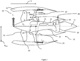
- a gas turbine engine is generally indicated at 10, having a principal and rotational axis 11. It will be understood that this figure is illustrative only, and is not to scale.
- the engine 10 comprises, in axial flow series, an air intake 12, a propulsive fan 13, a low pressure compressor 14, a high-pressure compressor 15, combustion equipment 16, a high-pressure turbine 17, a low-pressure turbine 18 and an exhaust nozzle 20.
- a nacelle 21 generally surrounds the engine 10 and defines both the intake 12 and the exhaust nozzle 20.
- the gas turbine engine 10 works in the conventional manner so that air entering the intake 12 is accelerated by the fan 13 to produce two air flows: a first air flow A into the low pressure compressor 14 and a second air flow B which passes through a bypass duct defined by an interior of the nacelle 21 to provide propulsive thrust.
- the low pressure compressor 14 compresses the air flow directed into it before delivering that air to the high pressure compressor 15 where further compression takes place.
- the compressed air exhausted from the high-pressure compressor 15 is directed into the combustion equipment 16 where it is mixed with fuel and the mixture combusted.
- the resultant hot combustion products then expand through, and thereby drive the high and low-pressure turbines 17, 18, before being exhausted through the nozzle 20 to provide additional propulsive thrust.
- the high 17, and low 18 pressure turbines drive respectively the high pressure compressor 15, low pressure compressor 14 and fan 13, each by suitable interconnecting shaft.
- a reduction gearbox (not shown) may be provided to link the fan 13 to the low pressure turbine 18.
- gas turbine engines to which the present disclosure may be applied may have alternative configurations.
- such engines may have an alternative number of interconnecting shafts (e.g. two) and/or an alternative number of compressors and/or turbines.
- the engine may comprise a gearbox provided in the drive train from a turbine to a compressor and/or fan.
- the compressors 14, 15, combustor 26 and turbines 17, 18 define a core, through which the first airflow A flows through an engine core inlet 34.
- the core is surrounded within a core housing arrangement comprising an inner core housing 22 and an outer core housing 23.
- the inner core housing provides an air-tight gas path for the core airflow A, while the outer core housing provides structural support for the core and the fan 13.
- the core and fan 13 are supported by front and rear mounting arrangements 24, 25.
- the front mounting arrangement 24 comprises a plurality of outlet guide vanes (OGVs) 26, which are shown in more detail in figure 2 , and described below.
- a plurality of OGVs are provided, which are distributed circumferentially around the engine 10.
- a radially inner end (“root”) 27 of each OGV 25 is mounted to an outer surface 28 of the outer core housing 23, while a radially outer end (“tip”) 29 of each OGV 26 is mounted to an inner surface 30 of the nacelle 21.
- the OGVs act as the supporting structure for the front portion of the engine, that is to say that the weight of the engine and any in flight loads are supported by the OGVs.
- additional support structure in the form of bifurcations is generally necessary. Consequently, the OGVs must be designed to be both structurally and aerodynamically efficient.
- a chord CHORD OGV can be defined by a distance between leading 31 and trailing edges 32 at a mid-span position.
- a span SPAN OGV can be defined as a distance between the root 27 and the tip 29 of the respective OGV 26 at the mid-chord position.
- the aspect ratio is between 4 and 8. This provides a relatively stiff, strong OGV, which can react large loads without bending or failure.
- the engine 10 has a bypass ratio of between 10 and 17, and in this example has a bypass ratio of approximately 10.
- the bypass can be defined as the ratio of the bypass mass flow B through the fan duct to the mass flow A through the core at a cruise condition.
- Gas turbine engines in accordance with the present disclosure may have any desired bypass ratio, where the bypass ratio is defined as the ratio of the mass flow rate of the flow through the bypass duct to the mass flow rate of the flow through the core at cruise conditions.
- the bypass ratio may be greater than (or in the order of) any of the following: 10, 10.5, 11, 11.5, 12, 12.5, 13, 13.5, 14, 14.5, 15, 15.5, 16, 16.5, or 17.
- the bypass ratio may be in an inclusive range bounded by any two of the values in the previous sentence (i.e. the values may form upper or lower bounds).
- the bypass duct may be substantially annular.
- a fan radius F OGV is defined by a distance from the longitudinal axis 11 and an aerodynamic tip 33 of the fan 13.
- an OGV radius R OGV is defined by a distance from the longitudinal axis 11 and an aerodynamic tip 29 of the OGV 26.
- a distance Y is defined as the axial distance between the air intake 12 to the bypass duct cowl 21 and a mid-chord of the outlet guide vanes 24 at the tip.
- a ratio between the distance Y and the outer radius R OGV of the outlet guide vanes 24 is typically between 1 and 1.7. This ratio is relatively
- a distance Xa is defined as the axial distance between the inlet centre of pressure 12 and the centre of the OGVs 26.
- the location of the inlet centre of pressure can be determined by summing the internal inlet pressures and external cowl pressures across the inlet. During manoeuvres (such as take-off from a runway), a force F i is generated at the forward end of the engine 10, effectively acting at the inlet 12.
- the intake upload may be calculated by summing the inlet internal and external surface pressures at a typical sizing case, e.g. high incidence take off rotation.
- a ratio of the outlet guide vane span SPAN OGV to the bypass fan radius R FAN is between 0.45 and 0.55. This parameter is believed to be unique in a high bypass turbofan having a bypass ratio between 8 and 12.
- the OGVs provide structural support for the front of the engine 10.
- they must also have high aerodynamic performance (i.e. provide low drag in use) and low weight. Consequently, it has been found that by providing a short span OGV relative to the bypass fan radius, a low weight, high strength OGV can be provided, which can support the engine in structurally and aerodynamically efficient manner. In particular, this has been found to result in a front structural support which is sufficiently stiff to prevent flexing of the fan case relative to the core casing, which could otherwise cause fatigue, and / or fan tip rubs.
- the OGV is provided at a large radial extent, i.e. the OGV root 27 is provided relatively far from the longitudinal axis. Consequently, a large flow area can be provided at the OGVs, in spite of their short span. Consequently, in the present disclosure a second ratio is defined.
- the second ratio is defined by a ratio of the OGV inner radial distance R ogv root to the OGV outer radial distance R ogv.
- the second ratio is between 0.5 and 0.6.
- the radial distances may be measured at the mid-chord position.
- the outer radius of the OGVs R OGV is generally equal to or greater than the radius of the fan R fan . Typically, the ratio is between 1 and 1.2. In contrast, in most conventional engine arrangements, the OGVs have a smaller diameter than the fan. This greater outer diameter of the OGVs, in conjunction with the large inner diameter R ogv root helps to enable a high bypass ratio with a short OGV, without necessitating a significant restriction at the OGVs, which would accelerate and possibly choke the flow, leading to a reduced pressure ratio across the fan and possible stalling, as well as increased fan noise due to the high velocity fan air.
- a third ratio is also defined.
- the third ratio is defied by the axial distance Xa , divided by the outer radius of the outlet guide vanes R ogv and is typically between 1 and 2.
- the OGV tip may be deflected radially inwardly or outwardly, though tip deflection is to some extent constrained by the fan cowl 21.
- the OGV tip may alternatively or in addition be deflected axially (forward or backward), or circumferentially.
- OGV tip deflection may be determined by measuring the net deflection in all axes.
- tip deflection may be determined by modelling the engine (for example, in a Finite Element model), and taking measurements from the model.
- the inventors have modelled a number of engines to determine optimum values of these parameters for various engine sizes and thrust ranges.
- a first engine is designed to provide between 75000 and 85000 pounds of thrust at maximum static flat rated takeoff thrust.
- the engine has an overall pressure ratio of approximately 50:1, and a bypass ratio of 15:1.
- the engine is of a two-spool, geared design, having a low pressure compressor coupled to a fan via a reduction gearbox, a high pressure compressor, and high and low pressure turbines).
- the ratio of the outlet guide vane span (OGV SPAN ) to the bypass fan radius (R FAN ) is approximately 0.54. Consequently, a high bypass ratio is provided, while a relatively short OGV is also provided, thereby resulting in a relatively strong, lightweight engine.
- the ratio of the inner radius of the outlet guide vanes and an outer radius of the outlet guide vanes is 0.5 for this engine.
- the ratio of the axial distance between the inlet to the bypass duct cowl and the mid chord of the outlet guide vanes at the tip, and an outer radius of the outlet guide vanes is 1.5 for this engine. Where a longer fan inlet is used, this ratio may increase to approximately 1.7.
- a second engine is designed to provide approximately 50,000 pounds of thrust at maximum static flat rated takeoff thrust.
- the engine has an overall pressure ratio of approximately 42:1, and a bypass ratio of 11.
- the engine is of a two-spool, geared design, having a low pressure compressor coupled to a fan via a reduction gearbox, a high pressure compressor, and high and low pressure turbines).
- the ratio of the outlet guide vane span (OGV SPAN ) to the bypass fan radius (R FAN ) is approximately 0.46. Again, a high bypass ratio is provided, while a relatively short OGV is also provided, thereby resulting in a relatively strong, lightweight engine. As can be seen, the disclosed ratio varies somewhat for engines having different thrust and bypass ratios, but remains within the disclosed range.
- the ratio of the inner radius of the outlet guide vanes and an outer radius of the outlet guide vanes is 0.53 for this engine.
- the ratio of the axial distance between the inlet to the bypass duct cowl and the mid chord of the outlet guide vanes at the tip, and an outer radius of the outlet guide vanes is 1.49 for this engine.
Landscapes
- Engineering & Computer Science (AREA)
- Mechanical Engineering (AREA)
- General Engineering & Computer Science (AREA)
- Chemical & Material Sciences (AREA)
- Combustion & Propulsion (AREA)
- Structures Of Non-Positive Displacement Pumps (AREA)
Applications Claiming Priority (1)
| Application Number | Priority Date | Filing Date | Title |
|---|---|---|---|
| GBGB1812875.1A GB201812875D0 (en) | 2018-08-08 | 2018-08-08 | Gas turbine engine mounting arrangement |
Publications (1)
| Publication Number | Publication Date |
|---|---|
| EP3608518A1 true EP3608518A1 (de) | 2020-02-12 |
Family
ID=63518463
Family Applications (1)
| Application Number | Title | Priority Date | Filing Date |
|---|---|---|---|
| EP19184996.7A Withdrawn EP3608518A1 (de) | 2018-08-08 | 2019-07-08 | Gasturbinenmotormontageanordnung |
Country Status (4)
| Country | Link |
|---|---|
| US (1) | US20200049022A1 (de) |
| EP (1) | EP3608518A1 (de) |
| CN (1) | CN110821574A (de) |
| GB (1) | GB201812875D0 (de) |
Cited By (1)
| Publication number | Priority date | Publication date | Assignee | Title |
|---|---|---|---|---|
| EP4407146A1 (de) * | 2023-01-27 | 2024-07-31 | Rolls-Royce plc | Gasturbinenmotor |
Families Citing this family (1)
| Publication number | Priority date | Publication date | Assignee | Title |
|---|---|---|---|---|
| US10844721B2 (en) * | 2019-03-13 | 2020-11-24 | Rolls-Royce Plc | Gas turbine engine for an aircraft |
Citations (2)
| Publication number | Priority date | Publication date | Assignee | Title |
|---|---|---|---|---|
| EP1340903A2 (de) * | 2002-03-01 | 2003-09-03 | General Electric Company | Gegenläufiges Bläsertriebwerk |
| US20110192166A1 (en) | 2010-02-08 | 2011-08-11 | Rolls-Royce Plc | Outlet guide vane structure |
-
2018
- 2018-08-08 GB GBGB1812875.1A patent/GB201812875D0/en not_active Ceased
-
2019
- 2019-07-08 EP EP19184996.7A patent/EP3608518A1/de not_active Withdrawn
- 2019-07-10 US US16/507,231 patent/US20200049022A1/en not_active Abandoned
- 2019-08-08 CN CN201910729560.3A patent/CN110821574A/zh active Pending
Patent Citations (2)
| Publication number | Priority date | Publication date | Assignee | Title |
|---|---|---|---|---|
| EP1340903A2 (de) * | 2002-03-01 | 2003-09-03 | General Electric Company | Gegenläufiges Bläsertriebwerk |
| US20110192166A1 (en) | 2010-02-08 | 2011-08-11 | Rolls-Royce Plc | Outlet guide vane structure |
Non-Patent Citations (4)
| Title |
|---|
| ANONYMOUS: "BAC.TVVD NK-93", 9 January 2004 (2004-01-09), XP055647349, Retrieved from the Internet <URL:https://web.archive.org/web/20040109111055/http://www.airwar.ru/enc/engines/nk-93.html> [retrieved on 20191128] * |
| ANONYMOUS: "Kuznetsov NK-93 - Wikipedia", 22 November 2019 (2019-11-22), XP055647330, Retrieved from the Internet <URL:https://en.wikipedia.org/wiki/Kuznetsov_NK-93> [retrieved on 20191128] * |
| ANONYMOUS: "OAO "Motopoctpoitelb"", 9 April 2010 (2010-04-09), XP055784846, Retrieved from the Internet <URL:https://web.archive.org/web/20100409082130/http://motor-s.ru/NK93.htm> [retrieved on 20210311] * |
| BANGALORE PHILIP R. GLIEBE ET AL: "Ultra-High Bypass Engine Aeroacoustic Study", NASA/CR-2003-212525, 1 October 2003 (2003-10-01), XP055277347, Retrieved from the Internet <URL:http://ntrs.nasa.gov/archive/nasa/casi.ntrs.nasa.gov/20040000741.pdf> [retrieved on 20160602] * |
Cited By (2)
| Publication number | Priority date | Publication date | Assignee | Title |
|---|---|---|---|---|
| EP4407146A1 (de) * | 2023-01-27 | 2024-07-31 | Rolls-Royce plc | Gasturbinenmotor |
| US12497894B2 (en) | 2023-01-27 | 2025-12-16 | Rolls-Royce Plc | Gas turbine engine |
Also Published As
| Publication number | Publication date |
|---|---|
| US20200049022A1 (en) | 2020-02-13 |
| CN110821574A (zh) | 2020-02-21 |
| GB201812875D0 (en) | 2018-09-19 |
Similar Documents
| Publication | Publication Date | Title |
|---|---|---|
| US20230415914A1 (en) | Advance ratio for single unducted rotor engine | |
| US10436035B1 (en) | Fan design | |
| US20210108572A1 (en) | Advance ratio for single unducted rotor engine | |
| US11499429B2 (en) | Rotor blade of a turbomachine | |
| US11156167B2 (en) | Casing | |
| EP3187712B1 (de) | Kurzer gondeleinlass | |
| EP2169182A2 (de) | Integrierte Leitschaufelanordnung | |
| EP3249232B1 (de) | Kompressionssystem für einen turbinenmotor | |
| US20180073518A1 (en) | Aircraft fan with low part-span solidity | |
| CN111350605B (zh) | 用于飞行器的气体涡轮引擎 | |
| CN111350606A (zh) | 齿轮传动气体涡轮引擎 | |
| EP3798415A1 (de) | Statorschaufelring oder -ringsegment | |
| US10330111B2 (en) | Gas turbine engine airfoil | |
| CN112796884A (zh) | 燃气涡轮发动机 | |
| CN111350613A (zh) | 航空引擎操作点 | |
| US12607124B2 (en) | Aeronautical propulsion system comprising an optimized fan section | |
| US11686248B2 (en) | Core duct assembly | |
| CN212272644U (zh) | 用于飞行器的气体涡轮引擎和飞行器 | |
| US20200049022A1 (en) | Gas turbine engine mounting arrangement | |
| EP3670862A1 (de) | Geräuscharmer gasturbinenmotor mit einem getriebe | |
| CN212225612U (zh) | 气体涡轮引擎和飞行器 | |
| EP3620610B1 (de) | Gasturbinentriebwerk | |
| CN111350608A (zh) | 气体涡轮引擎射流 | |
| EP3640465A1 (de) | Kaltdüsenoptimierung | |
| EP3170973B1 (de) | Strömungskanal eines turbinenmotors |
Legal Events
| Date | Code | Title | Description |
|---|---|---|---|
| PUAI | Public reference made under article 153(3) epc to a published international application that has entered the european phase |
Free format text: ORIGINAL CODE: 0009012 |
|
| STAA | Information on the status of an ep patent application or granted ep patent |
Free format text: STATUS: THE APPLICATION HAS BEEN PUBLISHED |
|
| AK | Designated contracting states |
Kind code of ref document: A1 Designated state(s): AL AT BE BG CH CY CZ DE DK EE ES FI FR GB GR HR HU IE IS IT LI LT LU LV MC MK MT NL NO PL PT RO RS SE SI SK SM TR |
|
| RAP1 | Party data changed (applicant data changed or rights of an application transferred) |
Owner name: ROLLS-ROYCE PLC |
|
| STAA | Information on the status of an ep patent application or granted ep patent |
Free format text: STATUS: REQUEST FOR EXAMINATION WAS MADE |
|
| 17P | Request for examination filed |
Effective date: 20200619 |
|
| RBV | Designated contracting states (corrected) |
Designated state(s): AL AT BE BG CH CY CZ DE DK EE ES FI FR GB GR HR HU IE IS IT LI LT LU LV MC MK MT NL NO PL PT RO RS SE SI SK SM TR |
|
| STAA | Information on the status of an ep patent application or granted ep patent |
Free format text: STATUS: EXAMINATION IS IN PROGRESS |
|
| 17Q | First examination report despatched |
Effective date: 20210318 |
|
| STAA | Information on the status of an ep patent application or granted ep patent |
Free format text: STATUS: THE APPLICATION IS DEEMED TO BE WITHDRAWN |
|
| 18D | Application deemed to be withdrawn |
Effective date: 20210729 |