EP3608563A1 - Joint d'étanchéité destiné à étanchéifier une fente périphérique entre deux composants de machine - Google Patents
Joint d'étanchéité destiné à étanchéifier une fente périphérique entre deux composants de machine Download PDFInfo
- Publication number
- EP3608563A1 EP3608563A1 EP18187429.8A EP18187429A EP3608563A1 EP 3608563 A1 EP3608563 A1 EP 3608563A1 EP 18187429 A EP18187429 A EP 18187429A EP 3608563 A1 EP3608563 A1 EP 3608563A1
- Authority
- EP
- European Patent Office
- Prior art keywords
- seal
- layer
- sheets
- shoe
- movable
- Prior art date
- Legal status (The legal status is an assumption and is not a legal conclusion. Google has not performed a legal analysis and makes no representation as to the accuracy of the status listed.)
- Granted
Links
Images


Classifications
-
- F—MECHANICAL ENGINEERING; LIGHTING; HEATING; WEAPONS; BLASTING
- F16—ENGINEERING ELEMENTS AND UNITS; GENERAL MEASURES FOR PRODUCING AND MAINTAINING EFFECTIVE FUNCTIONING OF MACHINES OR INSTALLATIONS; THERMAL INSULATION IN GENERAL
- F16J—PISTONS; CYLINDERS; SEALINGS
- F16J15/00—Sealings
- F16J15/44—Free-space packings
- F16J15/441—Free-space packings with floating ring
- F16J15/442—Free-space packings with floating ring segmented
-
- F—MECHANICAL ENGINEERING; LIGHTING; HEATING; WEAPONS; BLASTING
- F16—ENGINEERING ELEMENTS AND UNITS; GENERAL MEASURES FOR PRODUCING AND MAINTAINING EFFECTIVE FUNCTIONING OF MACHINES OR INSTALLATIONS; THERMAL INSULATION IN GENERAL
- F16J—PISTONS; CYLINDERS; SEALINGS
- F16J15/00—Sealings
- F16J15/16—Sealings between relatively-moving surfaces
Definitions
- the invention relates to a seal for sealing a peripheral gap between two machine components, one of the machine components being rotatably mounted in the axial direction relative to the other machine component, comprising: a main seal with at least one shoe for producing a non-contact seal between the machine components and with at least one spring element, which supports the shoe on one of the machine components such that radial movement of the shoe is possible in response to the application of fluid pressure to the shoe, and a secondary seal that seals the spring element in the axial direction, the secondary seal having at least two layers, the axial direction adjoin each other.
- a seal according to the preamble of claim 1 is for example from the publication US 2008/100000 A1 known.
- the seal is used in particular to seal the gap between the rotor and the housing of a turbomachine.
- the advantage of the seal described above is that the sealing gap is set by the volume flow acting through the seal and is therefore readjusted flexibly when the rotor and housing are in different positions.
- This principle of action is implemented in the so-called shoe, which is resiliently suspended from a carrier.
- This system is the main sealing system, also called the main seal.
- This radially flexible seal requires an axial secondary seal system or an auxiliary seal, which seals the changing axial gap just as flexibly. This takes place, for example, via two sheets, each of which is equipped with a spring system and is therefore pressed against a support and thus closes the opening gap towards the shoe. So that both spring systems, that of the shoe and that the secondary seal, can run parallel with low friction and at the same time the area of the spring system for the secondary seals remains covered, two components, an intermediate plate and a cover are provided. These have a game to the main sealing system and a space between each other for the secondary sealing system. For the application in a gas turbine, this principle of action must be realized by very filigree components.
- the invention has for its object to provide a seal that has an increased reliability of functionality compared to the prior art and is particularly suitable for use in a gas turbine.
- a seal for sealing a circumferential gap between two machine components, one of the machine components being rotatably mounted in the axial direction relative to the other machine component comprising: a main seal with at least one shoe for producing a non-contact seal between the machine components and with at least one a spring element which supports the shoe on one of the machine components in such a way that radial movement of the shoe is possible in response to the application of fluid pressure to the shoe, and a secondary seal which seals the spring element in the axial direction, the secondary seal having at least two layers, which adjoin one another in the axial direction, the layers each containing at least two sheets positioned radially next to one another, one sheet being fixed per layer and the other sheet being movably supported by being attached to the shoe Is established, with two movable sheets each two immediately adjacent Layers viewed in the radial direction have different widths, the wider of the two movable sheets for forming the layer is combined with a thinner, fixed sheet, and the thinner of the two movable
- the invention is based on the idea of proposing a sealing system in which no further spring systems are required, the susceptibility and complex design of which are regarded as one of the critical points of the known secondary sealing systems.
- the intermediate plate is dispensed with, as a result of which the critical interaction between a secondary seal according to the prior art and the intermediate plate is avoided. Since the secondary seal no longer has to be clamped, the reliability of the seal is considerably improved. In addition, the potential reworking is significantly reduced, since unevenness in the sheet metal of the secondary seal no longer plays a role. Thanks to the layered structure, the effort involved in assembling the seal is also considerably reduced. There are no longer complex systems on the secondary seals, which simplifies the design and assembly and reduces the number of tests when manufacturing the seal.
- layer is understood to mean a single sheet or a radial series of two or more sheets which have the same axial position.
- the axially outer layer radially overlaps parts of the adjacent layer in the maximally extended position. This can now be done alternately several times. Once the radial inner layer overlaps and once the radial outer layer overlaps. The shorter sheets, the Allow space for overlapping metal sheets are only to be understood as axial spacers, so that the next layer above is flat again.
- a further, single sheet can optionally be applied, which overlaps the underlying layers in the circumferential direction and is directly or indirectly attached to the carrier.
- This layer fulfills the protective function of the underlying thin and sensitive sheets for transport, installation and possibly also for operation.
- the sheets are expediently made of a high-temperature-resistant and / or corrosion-resistant material, in particular a steel.
- the movable sheets are made in particular from a material that maintains the surface quality required for the formation of sealing surfaces during the intended operating time and meets the requirements for strength during operation during this time.
- high-temperature resistant steels, nickel or cobalt-based alloys such as Inconel®, Haynes® or comparable materials can be selected.
- non-corrosive materials with sufficient strength are useful, which have the necessary surface quality for the formation of sealing surfaces over the service life.
- a plurality of movable sheets are provided per layer in the circumferential direction, and the wider, movable sheets of one layer overlap the thinner, movable sheets of the other layer in the circumferential direction.
- the resulting overlap in the circumferential direction additionally improves the sealing properties of the seal.
- the layers are contactless with one another at least in the overlap region arranged.
- temporarily thinner sheets can be introduced between the layer underneath and the new layer, which sheets are removed again after the sheets have been fastened in position.
- a certain amount of play can be achieved which reduces the friction between the sheet metal layers and does not block the system under the transverse force of the applied pressure.
- the sheets of a layer are preferably arranged without contact with one another. This is particularly the case when fluid pressure is exerted on the shoe of the seal.
- the radial gaps that arise between the sheets of a layer are sealed from the overlap of the sheets of two directly adjacent layers in the radial direction and possibly in the circumferential direction.
- the number of movable sheets preferably corresponds to the number of shoes at least in one layer.
- the movable sheets are designed in the shape of a segment of a circle and their size is optimally adapted to the size of the shoes.
- the fixed sheet of the innermost layer is preferably formed by an intermediate plate.
- This intermediate plate must be so stiff that it can bear the pressure of the other sheet metal layers. As a result, the axial forces are absorbed by the intermediate plate. Pressing of the movable shoe is therefore prevented, since these forces would impair functionality. This separates the interplay between moving parts and the rigid outer contour of the seal and ensures mobility. In the event that only a further layer of secondary seals is introduced in addition to the intermediate plate, the same basic functionality can be achieved with the smallest number of components.
- the movable sheets of the innermost layer are further preferably formed by a radial attachment of the shoes.
- the Movable sheets of the innermost layer are therefore an integral part of the shoes, which further reduces the number of components required and the fastening processes.
- the axially innermost layer and the outermost layer having the same structure.
- the axially innermost layer and the outermost layer each have either a thin, movable plate combined with a wide, fixed plate and the middle layer in between has a wide, movable plate combined with a thin, fixed plate, or vice versa.
- the movable plates are advantageously fastened to the shoes.
- the seal has a carrier for the main seal, the fixed sheets being attached to the carrier. This creates a secure, trouble-free connection between the movable sheets and the shoe and / or between the fixed sheets and the wearer, which cannot be released during operation. Games can be set directly during welding due to the layered structure. In addition, bumps can be ignored, since the sheets are welded on directly and the corresponding play can be set using temporary spacers. This eliminates in particular clamping and assembly devices.
- the sheets are e.g. welded on, soldered on, caulked in appropriate geometries or melted by additive processes or fastened by screws or rivets.
- the object is further achieved according to the invention by two machine components, one of the machine components being rotatably supported in the axial direction relative to the other machine component and a circumferential gap being formed between the two machine components, in which a seal is arranged according to one of the preceding claims, wherein the axial thickness of the axially innermost layer is selected such that the size of a gap between the shoe and the opposite machine component can be adjusted by the position of the secondary seal.
- the advantage here is that the required, contact-free gap between the seal and the machine components can be set within the technically acceptable limits via the leverage effect of the secondary seal, due to the position of the sheets.
- the axially innermost layer is preferably only arranged as a spacer without a sealing effect under the sealing layers.
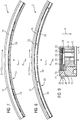
- FIG. 1 is part of a seal 2 for sealing a peripheral gap between two machine components, not shown here, which can be rotated relative to one another in the axial direction.
- the axial direction is symbolically marked with the point A, although although the spacing relationships are not observed in the drawing, point A is intended to represent the center of the circle which the complete seal 2 forms.
- point A is intended to represent the center of the circle which the complete seal 2 forms.
- R and U are also shown.
- the seal 2 comprises a main seal 4 with a plurality of so-called shoes 6 for producing a non-contact seal between the machine components.
- the shoes 6 are each spring-mounted on a carrier 10 via a spring element 8.
- the shoes 6 are supported on one of the machine components in such a way that a radial movement of the shoes is possible in response to the application of fluid pressure to the shoes 6.
- the seal 2 further comprises a secondary seal 12 constructed in layers, which seals the spring element 8 in the axial direction A, the secondary seal 12 having at least two layers which, viewed in the axial direction A, adjoin one another.
- a first layer 14 is in 2 and 3 shown.
- the first layer 14 is formed by two sheets 16, 18 positioned radially next to one another, in the form of segments of a circle or circle.
- the radially outer sheet 16 is fixed in that it is supported on the carrier 10.
- the radially inner sheet 18 is movably supported by being attached to the shoe 6 and itself moved with it in the radial direction.
- the radial space is not used symmetrically by the two sheets 16, 18.
- One of the two sheets 16, 18 is wider, the other thinner, this assignment being arbitrary (here the case is shown in which the radially outer and fixed sheet 16 is wider than the inner and movable sheet 18).
- the layer 14 is welded directly onto the main seal and the sheets 16, 18 should not touch each other in the maximum pressed position, therefore an inner gap 19 is formed between the two sheets 16, 18.
- a second layer 20 of the seal 2 is made of 4 and 5 seen.
- the second layer 20 also comprises a fixed plate 22 and a multi-part, movable plate 24, but in contrast to the first layer, the previously radially wider plate turns out to be thinner in this layer and vice versa (here the case is shown in which the radially outer and fixed plate 22 is thinner and the radially inner and movable plate 24 is wider).
- An intermediate gap 25 is present between the layers 14, 20, so that the layers 14, 20 are mounted without contact with one another.
- the alternation of thin and wide sheets means that the wider, movable sheet 24 of the second layer 20 overlaps the wider, fixed sheet 16 of the first layer 14.
- a barrier is thus formed for a fluid flowing in the axial direction A, so that the space behind the secondary seal 12, in particular the spring element 8, is axially sealed.
- the first layer 14 is formed from the wider, movable sheet metal combined with the thinner, fixed sheet metal and the second layer 20 from the thinner, movable sheet metal Sheet metal combined with the wider, fixed sheet metal is formed.
- the sheets 16, 18, 22, 24 of each layer 14, 20 have the same axial thickness or are at least in the same axial position.
- the fixed sheets 16, 22 serve in particular as a preparatory surface for the next layer, ie the height for the fixed sheet of the layer lying thereon is created by them.
- FIG 6 can be seen, from which also emerges a third layer 26.
- the third layer 26 contains a wider, fixed plate 28, supplemented by a thinner, movable plate 30.
- the first layer 14 and the third layer 26 thus have the same structure.
- the thicknesses and the gaps are designed in such a way that the axially prevailing compressive force always ensures that the sheets 16, 18, 22, 24 are touched, but prevents jamming with one another or due to the axial flexibility of the shoe 6.
- the fixed sheets 16, 22, 28 are in particular circular, semicircular or segment-shaped sheets.
- the movable sheets 18, 24, 30 are segmented.
- the number of movable sheets 18, 24, 30 corresponds to that of shoes 6; in the case of purely radial overlap, their length in circumferential direction U also corresponds approximately to the length of a shoe 6.
- the total length of all movable sheets corresponds 18, 24, 30 in the circumferential direction U approximately with the entire length of all shoes 6.
- the third layer 26 according to FIG 6 only consists of the wider, stationary sheet 28, which overlaps the wider, movable sheet or sheets 24 of the second layer 20.
- FIG 7 Another embodiment according to the invention is shown in 7 and 8 shown.
- a first layer 14 of the Secondary seal 12 can be seen, which according to the first layer 14 FIG 2 is identical.
- the fixed plate 22 is also the same as the fixed plate 22 according to FIG FIG 4 ,
- the segmented, movable sheets 34 are made longer in the circumferential direction, so that they overlap the movable sheets 18 of the first layer 14.
- this structure Comparable to the radial overlap, this structure also begins with a sheet 16 which is uninterrupted in the circumferential direction U in the radially outer, immovable area and with segmented, independent sheets 18 per shoe 6 in the movable area.
- This layer 14 is welded directly onto the main seal, caulked by appropriate grooves, soldered or melted by means of an additively manufactured construction and should not touch in the maximally pressed position.
- This base layer is required to avoid friction.
- the movable sheets 24, 30 and / or the fixed sheets 22, 28 can also form a unit in terms of construction and can be installed as such.
- the next layer 32 differs from the first approach in that the overlap occurs from a movable shoe 6 in the circumferential direction U to the next shoe 6.
- the next layer follows the same principle, but overlaps in the opposite direction.
- the layers 14, 32 lying one above the other can be separated from one another, if necessary, by thin spacer plates during welding, soldering or caulking, so that the friction is minimized and the above-mentioned gaps are achieved, which enable sealing under axial pressure load, but despite Resilience of the sheets 16, 18, 22, 24, 28, 30 itself but also of the shoe 6 and the spring elements 8 do not jam.
- a single, somewhat thicker fender (not shown here) can be applied continuously in the radially outer region, which overlaps the segmented, independent plates 34 in the radially inner region below. If no sheets in the radially outer, immovable area were inserted in the layers below, the corresponding gap (axial height of these sheets) must be taken into account. If this optional sheet is inserted, it must be so stiff that the pressure on the sheet pack can be borne. Here, too, it is advisable to introduce a minimum clearance through a temporary, thin intermediate layer during joining to avoid higher friction.
- FIG. 9 A further embodiment is shown in which the sealing effect of the secondary seal 12 is produced only by the second layer 20 and the third layer 26.
- the first layer 36 is a spacer layer and in this case comprises both a thin, fixed plate 16 and a thin, movable plate 18, between which there is a large internal gap 19.
- This layer 34 of fixed 16 and movable sheets 18 without a direct sealing effect under the sealing layers 20, 26 defines the axial position of the sealing layers 20, 26 in such a way that the requested, contact-free gap between the seal and the rotatable machine components (rotor) can be set within the technically acceptable limits. If the position of the secondary seal 12 is shifted axially upstream by a thicker spacer layer 36, then the gap between the main seal 4 and the rotating machine component opens.
- the spacer layer 36 is reduced and the position of the secondary seals 12 is therefore moved axially downstream, the gap between the main seal 12 and the rotating machine component closes. Therefore, by adjusting the thickness of this intermediate layer before the final joining, each seal can be subjected to a quality check, the appropriate thickness of this spacer layer 36 can be selected to meet the requirements for the gap between the main seal 4 and the rotating machine component and then to be finally assembled and joined.
Landscapes
- Engineering & Computer Science (AREA)
- General Engineering & Computer Science (AREA)
- Mechanical Engineering (AREA)
- Turbine Rotor Nozzle Sealing (AREA)
- Sealing Devices (AREA)
- Sealing Using Fluids, Sealing Without Contact, And Removal Of Oil (AREA)
Priority Applications (4)
| Application Number | Priority Date | Filing Date | Title |
|---|---|---|---|
| EP18187429.8A EP3608563B1 (fr) | 2018-08-06 | 2018-08-06 | Joint d'étanchéité destiné à étanchéifier une fente périphérique entre deux composants de machine |
| US16/528,466 US10591065B2 (en) | 2018-08-06 | 2019-07-31 | Seal for sealing a circumferential gap between two machine components |
| JP2019143777A JP6704496B2 (ja) | 2018-08-06 | 2019-08-05 | 2つの機械構成部材間にある周方向に延在する間隙をシールするためのシール |
| CN201910717100.9A CN110805693B (zh) | 2018-08-06 | 2019-08-05 | 用于密封两个机器部件之间的周向间隙的密封件 |
Applications Claiming Priority (1)
| Application Number | Priority Date | Filing Date | Title |
|---|---|---|---|
| EP18187429.8A EP3608563B1 (fr) | 2018-08-06 | 2018-08-06 | Joint d'étanchéité destiné à étanchéifier une fente périphérique entre deux composants de machine |
Publications (2)
| Publication Number | Publication Date |
|---|---|
| EP3608563A1 true EP3608563A1 (fr) | 2020-02-12 |
| EP3608563B1 EP3608563B1 (fr) | 2021-03-17 |
Family
ID=63165236
Family Applications (1)
| Application Number | Title | Priority Date | Filing Date |
|---|---|---|---|
| EP18187429.8A Active EP3608563B1 (fr) | 2018-08-06 | 2018-08-06 | Joint d'étanchéité destiné à étanchéifier une fente périphérique entre deux composants de machine |
Country Status (4)
| Country | Link |
|---|---|
| US (1) | US10591065B2 (fr) |
| EP (1) | EP3608563B1 (fr) |
| JP (1) | JP6704496B2 (fr) |
| CN (1) | CN110805693B (fr) |
Families Citing this family (1)
| Publication number | Priority date | Publication date | Assignee | Title |
|---|---|---|---|---|
| EP3885535B1 (fr) * | 2020-03-24 | 2022-09-07 | Siemens Energy Global GmbH & Co. KG | Bague d'étanchéité pour un rotor et rotor doté d'une telle bague d'étanchéité |
Citations (2)
| Publication number | Priority date | Publication date | Assignee | Title |
|---|---|---|---|---|
| US20080100000A1 (en) | 2003-05-01 | 2008-05-01 | Justak John F | Seal with stacked sealing elements |
| EP3290756A1 (fr) * | 2016-09-01 | 2018-03-07 | United Technologies Corporation | Lèvre verticale de joint d'étanchéité sans contact flottant |
Family Cites Families (6)
| Publication number | Priority date | Publication date | Assignee | Title |
|---|---|---|---|---|
| GB1493913A (en) * | 1975-06-04 | 1977-11-30 | Gen Motors Corp | Turbomachine stator interstage seal |
| DE4108226C2 (de) * | 1991-03-14 | 1993-11-04 | Kempchen & Co Gmbh | Dichtungsanordnung und verfahren zur herstellung |
| EP1508672A1 (fr) * | 2003-08-21 | 2005-02-23 | Siemens Aktiengesellschaft | Anneau de fixation segmenté pour une turbine |
| CN200940681Y (zh) * | 2006-08-29 | 2007-08-29 | 中信重型机械公司 | 一种用于回转类设备的新型密封装置 |
| CN203743434U (zh) * | 2014-03-24 | 2014-07-30 | 常州神力热喷涂技术有限公司 | 带有防尘垫圈的大型旋转平台车 |
| CN105587862B (zh) * | 2016-02-05 | 2019-05-24 | 沈阳耐蚀合金泵股份有限公司 | 应用于旋转机械的轴面机械密封 |
-
2018
- 2018-08-06 EP EP18187429.8A patent/EP3608563B1/fr active Active
-
2019
- 2019-07-31 US US16/528,466 patent/US10591065B2/en active Active
- 2019-08-05 JP JP2019143777A patent/JP6704496B2/ja active Active
- 2019-08-05 CN CN201910717100.9A patent/CN110805693B/zh active Active
Patent Citations (2)
| Publication number | Priority date | Publication date | Assignee | Title |
|---|---|---|---|---|
| US20080100000A1 (en) | 2003-05-01 | 2008-05-01 | Justak John F | Seal with stacked sealing elements |
| EP3290756A1 (fr) * | 2016-09-01 | 2018-03-07 | United Technologies Corporation | Lèvre verticale de joint d'étanchéité sans contact flottant |
Also Published As
| Publication number | Publication date |
|---|---|
| CN110805693B (zh) | 2021-08-27 |
| EP3608563B1 (fr) | 2021-03-17 |
| JP6704496B2 (ja) | 2020-06-03 |
| CN110805693A (zh) | 2020-02-18 |
| US20200041004A1 (en) | 2020-02-06 |
| US10591065B2 (en) | 2020-03-17 |
| JP2020024041A (ja) | 2020-02-13 |
Similar Documents
| Publication | Publication Date | Title |
|---|---|---|
| DE602004004195T2 (de) | Wellendichtungsvorrichtung | |
| DE2939945C2 (fr) | ||
| DE60207662T2 (de) | Bürstendichtung | |
| DE2455195B2 (de) | Bürstenförmige Dichtung zwischen zwei relativ zueinander beweglichen Maschinenteilen | |
| EP2041458B1 (fr) | Joint plat | |
| DE1600966B1 (de) | Mehrwegedrehschieber | |
| EP3330490B1 (fr) | Système d'étanchéité pour turbomachines | |
| DE3108748C2 (de) | Verschlußplatten-Einheit für einen Schiebeverschluß | |
| WO2016007980A1 (fr) | Lamelle à friction | |
| EP3608563B1 (fr) | Joint d'étanchéité destiné à étanchéifier une fente périphérique entre deux composants de machine | |
| DE4006498A1 (de) | Lamellendichtungen | |
| DE69715919T2 (de) | Plattenwärmetauscher | |
| EP0619447A1 (fr) | Joint plat métallique | |
| DE2262619C3 (de) | Mehreckiger Kolben für Kreiskolben-Brennkraftmaschinen und Verfahren zu seiner Herstellung | |
| DE69603086T2 (de) | Axiallageranordnung | |
| DE3329038C2 (de) | Kupplungsdruckplatte mit gewellten Drahtringen zur Abstützung der Membranfeder | |
| DE102019112614B3 (de) | Ölabstreifring mit einseitig angeordneten Rails | |
| EP2535606A1 (fr) | Agencement de palier axial | |
| DE1775396C3 (de) | Dichtungsring | |
| DE19512650A1 (de) | Zylinderkopfdichtung | |
| DE4338074A1 (de) | Kolbenring mit "Y"-Querschnitt | |
| DE19715759C1 (de) | Kolben für eine Hubkolbenbrennkraftmaschine | |
| EP3169916B1 (fr) | Unité de commande pour récepteurs à commande hydraulique | |
| EP3114295B1 (fr) | Système de verrouillage avec surfaces de contact | |
| DE2536847C3 (de) | Verfahren zur Auskleidung von nicht korrosionsbeständigen Flächen von Bauteilen |
Legal Events
| Date | Code | Title | Description |
|---|---|---|---|
| PUAI | Public reference made under article 153(3) epc to a published international application that has entered the european phase |
Free format text: ORIGINAL CODE: 0009012 |
|
| STAA | Information on the status of an ep patent application or granted ep patent |
Free format text: STATUS: THE APPLICATION HAS BEEN PUBLISHED |
|
| AK | Designated contracting states |
Kind code of ref document: A1 Designated state(s): AL AT BE BG CH CY CZ DE DK EE ES FI FR GB GR HR HU IE IS IT LI LT LU LV MC MK MT NL NO PL PT RO RS SE SI SK SM TR |
|
| AX | Request for extension of the european patent |
Extension state: BA ME |
|
| STAA | Information on the status of an ep patent application or granted ep patent |
Free format text: STATUS: REQUEST FOR EXAMINATION WAS MADE |
|
| 17P | Request for examination filed |
Effective date: 20200706 |
|
| RBV | Designated contracting states (corrected) |
Designated state(s): AL AT BE BG CH CY CZ DE DK EE ES FI FR GB GR HR HU IE IS IT LI LT LU LV MC MK MT NL NO PL PT RO RS SE SI SK SM TR |
|
| GRAP | Despatch of communication of intention to grant a patent |
Free format text: ORIGINAL CODE: EPIDOSNIGR1 |
|
| STAA | Information on the status of an ep patent application or granted ep patent |
Free format text: STATUS: GRANT OF PATENT IS INTENDED |
|
| INTG | Intention to grant announced |
Effective date: 20201113 |
|
| RAP1 | Party data changed (applicant data changed or rights of an application transferred) |
Owner name: SIEMENS ENERGY GLOBAL GMBH & CO. KG |
|
| GRAS | Grant fee paid |
Free format text: ORIGINAL CODE: EPIDOSNIGR3 |
|
| GRAA | (expected) grant |
Free format text: ORIGINAL CODE: 0009210 |
|
| STAA | Information on the status of an ep patent application or granted ep patent |
Free format text: STATUS: THE PATENT HAS BEEN GRANTED |
|
| AK | Designated contracting states |
Kind code of ref document: B1 Designated state(s): AL AT BE BG CH CY CZ DE DK EE ES FI FR GB GR HR HU IE IS IT LI LT LU LV MC MK MT NL NO PL PT RO RS SE SI SK SM TR |
|
| REG | Reference to a national code |
Ref country code: GB Ref legal event code: FG4D Free format text: NOT ENGLISH |
|
| REG | Reference to a national code |
Ref country code: CH Ref legal event code: EP |
|
| REG | Reference to a national code |
Ref country code: DE Ref legal event code: R096 Ref document number: 502018004322 Country of ref document: DE |
|
| REG | Reference to a national code |
Ref country code: IE Ref legal event code: FG4D Free format text: LANGUAGE OF EP DOCUMENT: GERMAN |
|
| REG | Reference to a national code |
Ref country code: AT Ref legal event code: REF Ref document number: 1372549 Country of ref document: AT Kind code of ref document: T Effective date: 20210415 |
|
| REG | Reference to a national code |
Ref country code: CH Ref legal event code: NV Representative=s name: SIEMENS SCHWEIZ AG, CH |
|
| REG | Reference to a national code |
Ref country code: LT Ref legal event code: MG9D |
|
| PG25 | Lapsed in a contracting state [announced via postgrant information from national office to epo] |
Ref country code: NO Free format text: LAPSE BECAUSE OF FAILURE TO SUBMIT A TRANSLATION OF THE DESCRIPTION OR TO PAY THE FEE WITHIN THE PRESCRIBED TIME-LIMIT Effective date: 20210617 Ref country code: HR Free format text: LAPSE BECAUSE OF FAILURE TO SUBMIT A TRANSLATION OF THE DESCRIPTION OR TO PAY THE FEE WITHIN THE PRESCRIBED TIME-LIMIT Effective date: 20210317 Ref country code: GR Free format text: LAPSE BECAUSE OF FAILURE TO SUBMIT A TRANSLATION OF THE DESCRIPTION OR TO PAY THE FEE WITHIN THE PRESCRIBED TIME-LIMIT Effective date: 20210618 Ref country code: FI Free format text: LAPSE BECAUSE OF FAILURE TO SUBMIT A TRANSLATION OF THE DESCRIPTION OR TO PAY THE FEE WITHIN THE PRESCRIBED TIME-LIMIT Effective date: 20210317 Ref country code: BG Free format text: LAPSE BECAUSE OF FAILURE TO SUBMIT A TRANSLATION OF THE DESCRIPTION OR TO PAY THE FEE WITHIN THE PRESCRIBED TIME-LIMIT Effective date: 20210617 |
|
| REG | Reference to a national code |
Ref country code: NL Ref legal event code: MP Effective date: 20210317 |
|
| PG25 | Lapsed in a contracting state [announced via postgrant information from national office to epo] |
Ref country code: RS Free format text: LAPSE BECAUSE OF FAILURE TO SUBMIT A TRANSLATION OF THE DESCRIPTION OR TO PAY THE FEE WITHIN THE PRESCRIBED TIME-LIMIT Effective date: 20210317 Ref country code: LV Free format text: LAPSE BECAUSE OF FAILURE TO SUBMIT A TRANSLATION OF THE DESCRIPTION OR TO PAY THE FEE WITHIN THE PRESCRIBED TIME-LIMIT Effective date: 20210317 Ref country code: SE Free format text: LAPSE BECAUSE OF FAILURE TO SUBMIT A TRANSLATION OF THE DESCRIPTION OR TO PAY THE FEE WITHIN THE PRESCRIBED TIME-LIMIT Effective date: 20210317 |
|
| PG25 | Lapsed in a contracting state [announced via postgrant information from national office to epo] |
Ref country code: NL Free format text: LAPSE BECAUSE OF FAILURE TO SUBMIT A TRANSLATION OF THE DESCRIPTION OR TO PAY THE FEE WITHIN THE PRESCRIBED TIME-LIMIT Effective date: 20210317 |
|
| PG25 | Lapsed in a contracting state [announced via postgrant information from national office to epo] |
Ref country code: SM Free format text: LAPSE BECAUSE OF FAILURE TO SUBMIT A TRANSLATION OF THE DESCRIPTION OR TO PAY THE FEE WITHIN THE PRESCRIBED TIME-LIMIT Effective date: 20210317 Ref country code: CZ Free format text: LAPSE BECAUSE OF FAILURE TO SUBMIT A TRANSLATION OF THE DESCRIPTION OR TO PAY THE FEE WITHIN THE PRESCRIBED TIME-LIMIT Effective date: 20210317 Ref country code: EE Free format text: LAPSE BECAUSE OF FAILURE TO SUBMIT A TRANSLATION OF THE DESCRIPTION OR TO PAY THE FEE WITHIN THE PRESCRIBED TIME-LIMIT Effective date: 20210317 Ref country code: LT Free format text: LAPSE BECAUSE OF FAILURE TO SUBMIT A TRANSLATION OF THE DESCRIPTION OR TO PAY THE FEE WITHIN THE PRESCRIBED TIME-LIMIT Effective date: 20210317 |
|
| PG25 | Lapsed in a contracting state [announced via postgrant information from national office to epo] |
Ref country code: IS Free format text: LAPSE BECAUSE OF FAILURE TO SUBMIT A TRANSLATION OF THE DESCRIPTION OR TO PAY THE FEE WITHIN THE PRESCRIBED TIME-LIMIT Effective date: 20210717 Ref country code: PL Free format text: LAPSE BECAUSE OF FAILURE TO SUBMIT A TRANSLATION OF THE DESCRIPTION OR TO PAY THE FEE WITHIN THE PRESCRIBED TIME-LIMIT Effective date: 20210317 Ref country code: PT Free format text: LAPSE BECAUSE OF FAILURE TO SUBMIT A TRANSLATION OF THE DESCRIPTION OR TO PAY THE FEE WITHIN THE PRESCRIBED TIME-LIMIT Effective date: 20210719 Ref country code: SK Free format text: LAPSE BECAUSE OF FAILURE TO SUBMIT A TRANSLATION OF THE DESCRIPTION OR TO PAY THE FEE WITHIN THE PRESCRIBED TIME-LIMIT Effective date: 20210317 Ref country code: RO Free format text: LAPSE BECAUSE OF FAILURE TO SUBMIT A TRANSLATION OF THE DESCRIPTION OR TO PAY THE FEE WITHIN THE PRESCRIBED TIME-LIMIT Effective date: 20210317 |
|
| REG | Reference to a national code |
Ref country code: DE Ref legal event code: R097 Ref document number: 502018004322 Country of ref document: DE |
|
| PLBE | No opposition filed within time limit |
Free format text: ORIGINAL CODE: 0009261 |
|
| STAA | Information on the status of an ep patent application or granted ep patent |
Free format text: STATUS: NO OPPOSITION FILED WITHIN TIME LIMIT |
|
| PG25 | Lapsed in a contracting state [announced via postgrant information from national office to epo] |
Ref country code: AL Free format text: LAPSE BECAUSE OF FAILURE TO SUBMIT A TRANSLATION OF THE DESCRIPTION OR TO PAY THE FEE WITHIN THE PRESCRIBED TIME-LIMIT Effective date: 20210317 Ref country code: DK Free format text: LAPSE BECAUSE OF FAILURE TO SUBMIT A TRANSLATION OF THE DESCRIPTION OR TO PAY THE FEE WITHIN THE PRESCRIBED TIME-LIMIT Effective date: 20210317 Ref country code: ES Free format text: LAPSE BECAUSE OF FAILURE TO SUBMIT A TRANSLATION OF THE DESCRIPTION OR TO PAY THE FEE WITHIN THE PRESCRIBED TIME-LIMIT Effective date: 20210317 |
|
| 26N | No opposition filed |
Effective date: 20211220 |
|
| PG25 | Lapsed in a contracting state [announced via postgrant information from national office to epo] |
Ref country code: SI Free format text: LAPSE BECAUSE OF FAILURE TO SUBMIT A TRANSLATION OF THE DESCRIPTION OR TO PAY THE FEE WITHIN THE PRESCRIBED TIME-LIMIT Effective date: 20210317 |
|
| PG25 | Lapsed in a contracting state [announced via postgrant information from national office to epo] |
Ref country code: MC Free format text: LAPSE BECAUSE OF FAILURE TO SUBMIT A TRANSLATION OF THE DESCRIPTION OR TO PAY THE FEE WITHIN THE PRESCRIBED TIME-LIMIT Effective date: 20210317 |
|
| REG | Reference to a national code |
Ref country code: BE Ref legal event code: MM Effective date: 20210831 |
|
| PG25 | Lapsed in a contracting state [announced via postgrant information from national office to epo] |
Ref country code: IS Free format text: LAPSE BECAUSE OF FAILURE TO SUBMIT A TRANSLATION OF THE DESCRIPTION OR TO PAY THE FEE WITHIN THE PRESCRIBED TIME-LIMIT Effective date: 20210717 Ref country code: LU Free format text: LAPSE BECAUSE OF NON-PAYMENT OF DUE FEES Effective date: 20210806 |
|
| PG25 | Lapsed in a contracting state [announced via postgrant information from national office to epo] |
Ref country code: IE Free format text: LAPSE BECAUSE OF NON-PAYMENT OF DUE FEES Effective date: 20210806 Ref country code: BE Free format text: LAPSE BECAUSE OF NON-PAYMENT OF DUE FEES Effective date: 20210831 |
|
| PG25 | Lapsed in a contracting state [announced via postgrant information from national office to epo] |
Ref country code: CY Free format text: LAPSE BECAUSE OF FAILURE TO SUBMIT A TRANSLATION OF THE DESCRIPTION OR TO PAY THE FEE WITHIN THE PRESCRIBED TIME-LIMIT Effective date: 20210317 |
|
| PG25 | Lapsed in a contracting state [announced via postgrant information from national office to epo] |
Ref country code: HU Free format text: LAPSE BECAUSE OF FAILURE TO SUBMIT A TRANSLATION OF THE DESCRIPTION OR TO PAY THE FEE WITHIN THE PRESCRIBED TIME-LIMIT; INVALID AB INITIO Effective date: 20180806 |
|
| PG25 | Lapsed in a contracting state [announced via postgrant information from national office to epo] |
Ref country code: MK Free format text: LAPSE BECAUSE OF FAILURE TO SUBMIT A TRANSLATION OF THE DESCRIPTION OR TO PAY THE FEE WITHIN THE PRESCRIBED TIME-LIMIT Effective date: 20210317 |
|
| PG25 | Lapsed in a contracting state [announced via postgrant information from national office to epo] |
Ref country code: MT Free format text: LAPSE BECAUSE OF FAILURE TO SUBMIT A TRANSLATION OF THE DESCRIPTION OR TO PAY THE FEE WITHIN THE PRESCRIBED TIME-LIMIT Effective date: 20210317 |
|
| REG | Reference to a national code |
Ref country code: AT Ref legal event code: MM01 Ref document number: 1372549 Country of ref document: AT Kind code of ref document: T Effective date: 20230806 |
|
| PG25 | Lapsed in a contracting state [announced via postgrant information from national office to epo] |
Ref country code: AT Free format text: LAPSE BECAUSE OF NON-PAYMENT OF DUE FEES Effective date: 20230806 |
|
| PG25 | Lapsed in a contracting state [announced via postgrant information from national office to epo] |
Ref country code: AT Free format text: LAPSE BECAUSE OF NON-PAYMENT OF DUE FEES Effective date: 20230806 |
|
| PGFP | Annual fee paid to national office [announced via postgrant information from national office to epo] |
Ref country code: DE Payment date: 20250827 Year of fee payment: 8 |
|
| PGFP | Annual fee paid to national office [announced via postgrant information from national office to epo] |
Ref country code: IT Payment date: 20250825 Year of fee payment: 8 |
|
| PGFP | Annual fee paid to national office [announced via postgrant information from national office to epo] |
Ref country code: GB Payment date: 20250826 Year of fee payment: 8 |
|
| PGFP | Annual fee paid to national office [announced via postgrant information from national office to epo] |
Ref country code: FR Payment date: 20250825 Year of fee payment: 8 |
|
| PGFP | Annual fee paid to national office [announced via postgrant information from national office to epo] |
Ref country code: CH Payment date: 20250901 Year of fee payment: 8 |
|
| PG25 | Lapsed in a contracting state [announced via postgrant information from national office to epo] |
Ref country code: TR Free format text: LAPSE BECAUSE OF FAILURE TO SUBMIT A TRANSLATION OF THE DESCRIPTION OR TO PAY THE FEE WITHIN THE PRESCRIBED TIME-LIMIT Effective date: 20210317 |
|
| PGFP | Annual fee paid to national office [announced via postgrant information from national office to epo] |
Ref country code: AT Payment date: 20260410 Year of fee payment: 5 |