EP3608582B1 - Mehrseitiges leuchtelement und dasselbe verwendende dreidimensionale beleuchtungsvorrichtung - Google Patents
Mehrseitiges leuchtelement und dasselbe verwendende dreidimensionale beleuchtungsvorrichtung Download PDFInfo
- Publication number
- EP3608582B1 EP3608582B1 EP18832391.9A EP18832391A EP3608582B1 EP 3608582 B1 EP3608582 B1 EP 3608582B1 EP 18832391 A EP18832391 A EP 18832391A EP 3608582 B1 EP3608582 B1 EP 3608582B1
- Authority
- EP
- European Patent Office
- Prior art keywords
- light
- exit portion
- light guide
- guide member
- light emitting
- Prior art date
- Legal status (The legal status is an assumption and is not a legal conclusion. Google has not performed a legal analysis and makes no representation as to the accuracy of the status listed.)
- Active
Links
Images










Classifications
-
- F—MECHANICAL ENGINEERING; LIGHTING; HEATING; WEAPONS; BLASTING
- F21—LIGHTING
- F21K—NON-ELECTRIC LIGHT SOURCES USING LUMINESCENCE; LIGHT SOURCES USING ELECTROCHEMILUMINESCENCE; LIGHT SOURCES USING CHARGES OF COMBUSTIBLE MATERIAL; LIGHT SOURCES USING SEMICONDUCTOR DEVICES AS LIGHT-GENERATING ELEMENTS; LIGHT SOURCES NOT OTHERWISE PROVIDED FOR
- F21K9/00—Light sources using semiconductor devices as light-generating elements, e.g. using light-emitting diodes [LED] or lasers
- F21K9/20—Light sources comprising attachment means
-
- F—MECHANICAL ENGINEERING; LIGHTING; HEATING; WEAPONS; BLASTING
- F21—LIGHTING
- F21K—NON-ELECTRIC LIGHT SOURCES USING LUMINESCENCE; LIGHT SOURCES USING ELECTROCHEMILUMINESCENCE; LIGHT SOURCES USING CHARGES OF COMBUSTIBLE MATERIAL; LIGHT SOURCES USING SEMICONDUCTOR DEVICES AS LIGHT-GENERATING ELEMENTS; LIGHT SOURCES NOT OTHERWISE PROVIDED FOR
- F21K9/00—Light sources using semiconductor devices as light-generating elements, e.g. using light-emitting diodes [LED] or lasers
- F21K9/60—Optical arrangements integrated in the light source, e.g. for improving the colour rendering index or the light extraction
- F21K9/61—Optical arrangements integrated in the light source, e.g. for improving the colour rendering index or the light extraction using light guides
-
- B—PERFORMING OPERATIONS; TRANSPORTING
- B60—VEHICLES IN GENERAL
- B60Q—ARRANGEMENT OF SIGNALLING OR LIGHTING DEVICES, THE MOUNTING OR SUPPORTING THEREOF OR CIRCUITS THEREFOR, FOR VEHICLES IN GENERAL
- B60Q1/00—Arrangement of optical signalling or lighting devices, the mounting or supporting thereof or circuits therefor
- B60Q1/26—Arrangement of optical signalling or lighting devices, the mounting or supporting thereof or circuits therefor the devices being primarily intended to indicate the vehicle, or parts thereof, or to give signals, to other traffic
- B60Q1/2696—Mounting of devices using LEDs
-
- F—MECHANICAL ENGINEERING; LIGHTING; HEATING; WEAPONS; BLASTING
- F21—LIGHTING
- F21S—NON-PORTABLE LIGHTING DEVICES; SYSTEMS THEREOF; VEHICLE LIGHTING DEVICES SPECIALLY ADAPTED FOR VEHICLE EXTERIORS
- F21S41/00—Illuminating devices specially adapted for vehicle exteriors, e.g. headlamps
- F21S41/30—Illuminating devices specially adapted for vehicle exteriors, e.g. headlamps characterised by reflectors
-
- F—MECHANICAL ENGINEERING; LIGHTING; HEATING; WEAPONS; BLASTING
- F21—LIGHTING
- F21S—NON-PORTABLE LIGHTING DEVICES; SYSTEMS THEREOF; VEHICLE LIGHTING DEVICES SPECIALLY ADAPTED FOR VEHICLE EXTERIORS
- F21S43/00—Signalling devices specially adapted for vehicle exteriors, e.g. brake lamps, direction indicator lights or reversing lights
- F21S43/10—Signalling devices specially adapted for vehicle exteriors, e.g. brake lamps, direction indicator lights or reversing lights characterised by the light source
- F21S43/13—Signalling devices specially adapted for vehicle exteriors, e.g. brake lamps, direction indicator lights or reversing lights characterised by the light source characterised by the type of light source
- F21S43/14—Light emitting diodes [LED]
-
- F—MECHANICAL ENGINEERING; LIGHTING; HEATING; WEAPONS; BLASTING
- F21—LIGHTING
- F21S—NON-PORTABLE LIGHTING DEVICES; SYSTEMS THEREOF; VEHICLE LIGHTING DEVICES SPECIALLY ADAPTED FOR VEHICLE EXTERIORS
- F21S43/00—Signalling devices specially adapted for vehicle exteriors, e.g. brake lamps, direction indicator lights or reversing lights
- F21S43/20—Signalling devices specially adapted for vehicle exteriors, e.g. brake lamps, direction indicator lights or reversing lights characterised by refractors, transparent cover plates, light guides or filters
- F21S43/235—Light guides
-
- F—MECHANICAL ENGINEERING; LIGHTING; HEATING; WEAPONS; BLASTING
- F21—LIGHTING
- F21S—NON-PORTABLE LIGHTING DEVICES; SYSTEMS THEREOF; VEHICLE LIGHTING DEVICES SPECIALLY ADAPTED FOR VEHICLE EXTERIORS
- F21S43/00—Signalling devices specially adapted for vehicle exteriors, e.g. brake lamps, direction indicator lights or reversing lights
- F21S43/20—Signalling devices specially adapted for vehicle exteriors, e.g. brake lamps, direction indicator lights or reversing lights characterised by refractors, transparent cover plates, light guides or filters
- F21S43/235—Light guides
- F21S43/236—Light guides characterised by the shape of the light guide
- F21S43/239—Light guides characterised by the shape of the light guide plate-shaped
-
- F—MECHANICAL ENGINEERING; LIGHTING; HEATING; WEAPONS; BLASTING
- F21—LIGHTING
- F21S—NON-PORTABLE LIGHTING DEVICES; SYSTEMS THEREOF; VEHICLE LIGHTING DEVICES SPECIALLY ADAPTED FOR VEHICLE EXTERIORS
- F21S43/00—Signalling devices specially adapted for vehicle exteriors, e.g. brake lamps, direction indicator lights or reversing lights
- F21S43/20—Signalling devices specially adapted for vehicle exteriors, e.g. brake lamps, direction indicator lights or reversing lights characterised by refractors, transparent cover plates, light guides or filters
- F21S43/235—Light guides
- F21S43/242—Light guides characterised by the emission area
- F21S43/245—Light guides characterised by the emission area emitting light from one or more of its major surfaces
-
- F—MECHANICAL ENGINEERING; LIGHTING; HEATING; WEAPONS; BLASTING
- F21—LIGHTING
- F21S—NON-PORTABLE LIGHTING DEVICES; SYSTEMS THEREOF; VEHICLE LIGHTING DEVICES SPECIALLY ADAPTED FOR VEHICLE EXTERIORS
- F21S43/00—Signalling devices specially adapted for vehicle exteriors, e.g. brake lamps, direction indicator lights or reversing lights
- F21S43/20—Signalling devices specially adapted for vehicle exteriors, e.g. brake lamps, direction indicator lights or reversing lights characterised by refractors, transparent cover plates, light guides or filters
- F21S43/235—Light guides
- F21S43/242—Light guides characterised by the emission area
- F21S43/246—Light guides characterised by the emission area having two or more output branches
-
- F—MECHANICAL ENGINEERING; LIGHTING; HEATING; WEAPONS; BLASTING
- F21—LIGHTING
- F21S—NON-PORTABLE LIGHTING DEVICES; SYSTEMS THEREOF; VEHICLE LIGHTING DEVICES SPECIALLY ADAPTED FOR VEHICLE EXTERIORS
- F21S43/00—Signalling devices specially adapted for vehicle exteriors, e.g. brake lamps, direction indicator lights or reversing lights
- F21S43/20—Signalling devices specially adapted for vehicle exteriors, e.g. brake lamps, direction indicator lights or reversing lights characterised by refractors, transparent cover plates, light guides or filters
- F21S43/235—Light guides
- F21S43/249—Light guides with two or more light sources being coupled into the light guide
-
- F—MECHANICAL ENGINEERING; LIGHTING; HEATING; WEAPONS; BLASTING
- F21—LIGHTING
- F21S—NON-PORTABLE LIGHTING DEVICES; SYSTEMS THEREOF; VEHICLE LIGHTING DEVICES SPECIALLY ADAPTED FOR VEHICLE EXTERIORS
- F21S43/00—Signalling devices specially adapted for vehicle exteriors, e.g. brake lamps, direction indicator lights or reversing lights
- F21S43/20—Signalling devices specially adapted for vehicle exteriors, e.g. brake lamps, direction indicator lights or reversing lights characterised by refractors, transparent cover plates, light guides or filters
- F21S43/235—Light guides
- F21S43/249—Light guides with two or more light sources being coupled into the light guide
- F21S43/2492—Light guides with two or more light sources being coupled into the light guide having two or more input branches
-
- G—PHYSICS
- G02—OPTICS
- G02B—OPTICAL ELEMENTS, SYSTEMS OR APPARATUS
- G02B5/00—Optical elements other than lenses
- G02B5/02—Diffusing elements; Afocal elements
-
- G—PHYSICS
- G02—OPTICS
- G02B—OPTICAL ELEMENTS, SYSTEMS OR APPARATUS
- G02B6/00—Light guides; Structural details of arrangements comprising light guides and other optical elements, e.g. couplings
- G02B6/0001—Light guides; Structural details of arrangements comprising light guides and other optical elements, e.g. couplings specially adapted for lighting devices or systems
- G02B6/0011—Light guides; Structural details of arrangements comprising light guides and other optical elements, e.g. couplings specially adapted for lighting devices or systems the light guides being planar or of plate-like form
- G02B6/0033—Means for improving the coupling-out of light from the light guide
- G02B6/0035—Means for improving the coupling-out of light from the light guide provided on the surface of the light guide or in the bulk of it
- G02B6/0036—2-D arrangement of prisms, protrusions, indentations or roughened surfaces
-
- G—PHYSICS
- G02—OPTICS
- G02B—OPTICAL ELEMENTS, SYSTEMS OR APPARATUS
- G02B6/00—Light guides; Structural details of arrangements comprising light guides and other optical elements, e.g. couplings
- G02B6/0001—Light guides; Structural details of arrangements comprising light guides and other optical elements, e.g. couplings specially adapted for lighting devices or systems
- G02B6/0011—Light guides; Structural details of arrangements comprising light guides and other optical elements, e.g. couplings specially adapted for lighting devices or systems the light guides being planar or of plate-like form
- G02B6/0033—Means for improving the coupling-out of light from the light guide
- G02B6/0035—Means for improving the coupling-out of light from the light guide provided on the surface of the light guide or in the bulk of it
- G02B6/0038—Linear indentations or grooves, e.g. arc-shaped grooves or meandering grooves, extending over the full length or width of the light guide
-
- G—PHYSICS
- G02—OPTICS
- G02B—OPTICAL ELEMENTS, SYSTEMS OR APPARATUS
- G02B6/00—Light guides; Structural details of arrangements comprising light guides and other optical elements, e.g. couplings
- G02B6/0001—Light guides; Structural details of arrangements comprising light guides and other optical elements, e.g. couplings specially adapted for lighting devices or systems
- G02B6/0011—Light guides; Structural details of arrangements comprising light guides and other optical elements, e.g. couplings specially adapted for lighting devices or systems the light guides being planar or of plate-like form
- G02B6/0033—Means for improving the coupling-out of light from the light guide
- G02B6/0035—Means for improving the coupling-out of light from the light guide provided on the surface of the light guide or in the bulk of it
- G02B6/0045—Means for improving the coupling-out of light from the light guide provided on the surface of the light guide or in the bulk of it by shaping at least a portion of the light guide
- G02B6/0046—Tapered light guide, e.g. wedge-shaped light guide
-
- F—MECHANICAL ENGINEERING; LIGHTING; HEATING; WEAPONS; BLASTING
- F21—LIGHTING
- F21Y—INDEXING SCHEME ASSOCIATED WITH SUBCLASSES F21K, F21L, F21S and F21V, RELATING TO THE FORM OR THE KIND OF THE LIGHT SOURCES OR OF THE COLOUR OF THE LIGHT EMITTED
- F21Y2101/00—Point-like light sources
-
- F—MECHANICAL ENGINEERING; LIGHTING; HEATING; WEAPONS; BLASTING
- F21—LIGHTING
- F21Y—INDEXING SCHEME ASSOCIATED WITH SUBCLASSES F21K, F21L, F21S and F21V, RELATING TO THE FORM OR THE KIND OF THE LIGHT SOURCES OR OF THE COLOUR OF THE LIGHT EMITTED
- F21Y2105/00—Planar light sources
- F21Y2105/10—Planar light sources comprising a two-dimensional [2D] array of point-like light-generating elements
-
- F—MECHANICAL ENGINEERING; LIGHTING; HEATING; WEAPONS; BLASTING
- F21—LIGHTING
- F21Y—INDEXING SCHEME ASSOCIATED WITH SUBCLASSES F21K, F21L, F21S and F21V, RELATING TO THE FORM OR THE KIND OF THE LIGHT SOURCES OR OF THE COLOUR OF THE LIGHT EMITTED
- F21Y2115/00—Light-generating elements of semiconductor light sources
- F21Y2115/10—Light-emitting diodes [LED]
Definitions
- the present invention relates to a multi-sided luminous lighting member and a three-dimensional lighting device using the same, and more particularly, to a multi-sided luminous lighting member which is mounted to a structure having a three-dimensional shape, such as an automobile, so as to be used for the purpose of lighting, signaling, decoration, and the like, and a three-dimensional lighting device using the same.
- a lamp assembly for an automobile has a lighting function for assisting a driver in recognizing an object with the naked eye at night or in bad weather where there is a lack of natural light, and the lamp assembly has a signaling function for indicating a state of the automobile to the outside.
- headlamps or fog lamps mainly serve to provide lighting
- turn signal lamps, tail lamps, and brake lamps mainly serve to provide signals.
- various lamp assemblies are installed inside/outside the automobile and used to indicate a position of a particular manipulating device or used for the purpose of decoration or indication of a state of the automobile.
- a light-emitting diode In comparison with light sources in the related art, a light-emitting diode (LED) has lots of advantages in that the light-emitting diode does not use harmful substances such as mercury and thus causes less environmental pollution, and the light-emitting diode has a long lifespan, low electric power consumption, and excellent visibility, and causes less light blindness. Recently, the LEDs are widely used for lighting devices for automobiles in accordance with rapid developments of technologies associated with the LEDs such as high-brightness light-emitting diodes.
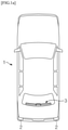
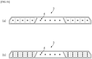
- Korean Patent Application Laid-Open No. 2014-0131897 discloses a point-light-emitting type auxiliary brake lamp 3 for an automobile 1 that uses LEDs as illustrated in FIGS. 1A and 1B , in which a plurality of LEDs 4 is disposed to be spaced apart from one another or disposed in groups so as to ensure a lighting width of the auxiliary brake lamp which is a predetermined standard or higher determined by the related regulations.
- the amount of light greatly varies depending on positions on surfaces of the LEDs on the brake lamp because the arrangement positions of the plurality of LEDs directly affect a light emitting pattern of the brake lamp which is recognized from the outside. For this reason, only particular points, where the respective LEDs are positioned, are conspicuously and visually recognized in the form of local point light sources when viewing the brake lamp from the rear side, but linear light sources or surface light sources, which have entirely uniform light emitting patterns, cannot be implemented. If arrangement intervals are decreased by increasing the number of LEDs to avoid the above-mentioned problems, there is a problem in that component costs increase. There is also a problem in that the component costs, the number of components, and an overall module thickness also increase even if a diffusion plate or the like is disposed on the surface.
- a lighting structure having a three-dimensional light emitting pattern is sometimes implemented by three-dimensionally arranging several light source modules and coupling the respective light source modules to members having different properties and effects.
- the implemented lighting structure is not greatly different from a lighting structure in the related art because the three-dimensional light emitting pattern cannot be appropriately implemented due to a very complicated structure, a high unit price, and a mechanical limitation.
- FIG. 2B there is an attempt made to implement a lighting structure having a three-dimensional light emitting pattern by using an organic light emitting diode (OLED) panel in order to solve the above-mentioned problem.
- OLED organic light emitting diode
- the manufacturing costs may be greatly increased, a separate light source needs to be added because it is difficult to adjust a light amount reference value required for a brake lamp (stop lamp) and the like, and it is difficult to satisfy high reliability required for an automobile and the like, and thus there remain a lot of problems to be solved.
- a light for vehicles is known from DE 10 2010 061 210 A1 .
- This light comprises a first and a second light source.
- the first light source is connected with a light guide member.
- the first light source comprises several LEDs positioned at the light incident portion of the light guide member.
- This light guide member has a first and second lateral exit portion for emitting light. Perpendicular thereto are provided an upper and lower surface, which are provided for a total reflection of the incident light.
- the present invention has been made in an effort to solve the above-mentioned problem and to provide a multi-sided luminous lighting member which is easily applied to an automobile having a complex three-dimensional structure and may implement a multi-sided light emitting structure including a surface light source together with an ideal linear light source having a uniform light emitting pattern, and a three-dimensional lighting device using the same.
- the present invention has also been made in an effort to provide a multi-sided luminous lighting member which may reduce manufacturing costs, may be easily applied without worry in view of component costs and component complexity even though designs of automobiles are changed by automobile manufacturers or new automobile designs are made, and may improve versatility as an automobile component, and a three-dimensional lighting device using the same.
- the present invention has also been made in an effort to provide a basic material/component infrastructure capable of being utilized to easily implement various high-grade designs by automobile manufacturers by supplying lighting members which are modularized and light in weight and have flexibility.
- a lighting member includes: a light guide member which is a multi-sided light-transmitting light guide member having a plurality of surfaces and has a light incident portion which is at least one of the plurality of surfaces, a first light exit portion which is at least one other surface opposite to the light incident portion among the plurality of surfaces, and a second light exit portion which is at least one other surface positioned laterally in a direction in which light entering the light incident portion travels toward the first light exit portion, such that the first light exit portion and the second light exit portion emit the light that has entered the light incident portion; a plurality of light emitting diodes disposed at predetermined intervals adjacent to the light incident portion to allow the light to enter the light incident portion; and a mounting board connected to the light guide member and having a surface on which the plurality of light emitting diodes are disposed, in which a concave-convex portion is formed on a surface of the first light exit portion to mitigate irregularity of a light emitting pattern on the first light exit
- the light guide member includes a light guide film, the light incident portion includes one edge surface of the light guide film, the first light exit portion implements a linear light source, and the second light exit portion implements a surface light source.
- a predetermined pattern is formed on a surface of the second light exit portion to emit a part of the light that enters the light incident portion and travels toward the first light exit portion.
- a pattern may be formed on a surface of the second light exit portion so that a brightness difference is made in a particular direction.
- the lighting member may further include a bezel portion attached to an upper or lower surface of the light guide member, in which the bezel portion adjusts a light emitting pattern on the second light exit portion by using one or more of shape, color, and surface treatments.
- the bezel portion may fix the light guide member and the mounting board.
- the bezel portion may have a reflective surface configured to reflect the light exiting the second light exit portion.
- the light guide member may be a light guide film having a thickness of 0.1 mm to 4.0 mm.
- the light guide member may be an injection-molded light guide film having a thickness of 2.0 mm to 20.0 mm.
- the light incident portion may face the plurality of light emitting diodes, and the first light exit portion may be positioned at a side opposite to a side of the light incident portion on a plane of the light guide member.
- concave-convex portions having one or two or more shapes may be repeatedly disposed at predetermined intervals on the surface of the first light exit portion.
- a thickness of the light guide film at a side of the first light exit portion and a thickness of the light guide film at a side of the light incident portion may be different from each other.
- the light guide film may have a tapered cross section, and a thickness of the light guide film at a side of the first light exit portion may be greater than a thickness of the light guide film at a side of the light incident portion.
- the light guide film may include a curved portion bent at a predetermined angle.
- a three-dimensional lighting device may implement a three-dimensional light emitting pattern by arranging the plurality of lighting members.
- the three-dimensional lighting device may further include a control unit capable of individually controlling and sequentially operating the plurality of arranged lighting members.
- a method of manufacturing a lighting member includes: forming a light guide member which is a multi-sided light-transmitting light guide member having a plurality of surfaces and has a light incident portion which is at least one of the plurality of surfaces, a first light exit portion which is at least one other surface opposite to the light incident portion among the plurality of surfaces, and a second light exit portion which is at least one other surface positioned laterally in a direction in which light entering the light incident portion travels toward the first light exit portion, such that the first light exit portion and the second light exit portion emit the light that has entered the light incident portion; disposing a plurality of light emitting diodes at predetermined intervals on a mounting board adjacent to the light incident portion to allow the light to enter the light incident portion; coupling the light guide member to the mounting board having a surface on which the plurality of light emitting diodes is disposed; and connecting the mounting board to a drive module configured to electrically operate the plurality of light emitting diodes, in which
- the light guide member in the forming of the light guide member, may be formed by cutting and separating a flexible light-transmitting resin film.
- the light guide member may be formed by injection-molding light-transmitting resin.
- the multi-sided luminous lighting member which is easily applied to internal and external structures of an automobile having a complex three-dimensional structure and may implement a multi-sided light emitting structure including a surface light source together with an ideal linear light source having a uniform light emitting pattern, and a three-dimensional lighting device using the same.
- the multi-sided luminous lighting member which may reduce manufacturing costs, may be easily applied without worry in view of component costs and component complexity even though designs of automobiles are changed by automobile manufacturers or new automobile designs are made, and may improve versatility as an automobile component, and a three-dimensional lighting device using the same.
- the basic material/component infrastructure capable of being utilized to easily implement various high-grade designs for vehicle manufacturers by supplying the lighting members which are modularized and light in weight and have flexibility.
- first and second used in the present invention may be used to describe constituent elements, but the constituent elements should not be limited by the terms. These terms are used only to distinguish one constituent element from another constituent element.
- a first constituent element may be named a second constituent element, and similarly, the second constituent element may also be named the first constituent element, without departing from the scope of the present invention.
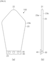
- FIG. 3 illustrates a multi-sided luminous lighting member 100 according to an exemplary embodiment of the present invention.
- the multi-sided luminous lighting member 100 includes one or more light emitting diodes 30, a light guide member 20 configured to guide light entering from the one or more light emitting diodes 30 and allow the light to exit respective light emitting surfaces, and a mounting board 40 on which the one or more light emitting diodes 30 are mounted.
- the light guide member 20 is a light-transmitting light guide member 20 having the plurality of light emitting surfaces and has a light incident portion 24 which is at least one of the plurality of light emitting surfaces, a first light exit portion 22 which is at least one other light emitting surface opposite to the light incident portion 24 among the plurality of light emitting surfaces, and a second light exit portion 23 which is at least one other light emitting surface positioned laterally in a direction in which the light entering the light incident portion 24 travels toward the first light exit portion 22.
- the first light exit portion 22 and the second light exit portion 23 emit the light that has entered the light incident portion 22.
- the light emitting diode 30 is disposed adjacent to the light incident portion 24 and emits the light so that the light enters the light incident surface 22 of the light guide member 20.
- a side-view light emitting diode 30 may be used as the light emitting diode 30, but the present invention is not limited thereto, and a top-view light emitting diode 30 may also be used.
- the one or more light emitting diodes 30 are disposed on a surface of the mounting board 40, and the mounting board 40 is structured to be connected to the light guide member 20.
- a general PCB rigid type
- the mounting board 40 may be implemented by using a metal PCB or using an aluminum plate for a flexible PCB in consideration of heat dissipation.
- the light which is emitted from the one or more light emitting diodes 30 and enters the light incident portion 24, exits the first light exit portion 22 opposite to the light incident portion 24 as well as the second light exit portion 23 which is at least one other surface positioned laterally in the direction in which the light travels toward the first light exit portion 22. Accordingly, in the lighting member 100 according to the exemplary embodiment of the present invention, the light exits the first light exit portion 22 and the second light exit portion 23, thereby implementing a multi-sided light emitting property.
- the light guide member 20 includes a light guide film.
- the light-transmitting resin film which is made of acrylic-based resin (PMMA) having high transmittance in a wavelength region of visible light or polycarbonate (PC) having high transmittance and excellent mechanical strength, may be used as the light guide member 20.
- PMMA acrylic-based resin
- PC polycarbonate
- PC which may ensure durability even though the light guide film is thin, is more preferable in a case in which the light guide film is used in the form of a film in the exemplary embodiment of the present invention.
- a thickness of the light guide film ranges preferably from 0.2 mm to 3.0 mm, and more preferably, the thickness may range from 0.3 mm to 2.0 mm to maintain mechanical durability and ensure high flexibility.
- the light-transmitting resin film within these ranges may be easily available on the market because the light-transmitting resin film may be easily mass-produced by a method such as rolling without using an expensive process such as injection molding, and as a result, it is possible to greatly reduce manufacturing costs of the lighting member 100.
- the light incident portion 24 includes one edge surface of the light guide film. Therefore, the first light exit portion 22 is configured as a linear light source at the other edge surface opposite to one edge surface of the light incident portion 24. Further, the second light exit portion 23 is configured as a surface light source at one or more lateral sides laterally positioned in the direction in which the light travels from the light incident portion 24 toward the first light exit portion 22.
- a concave-convex portion is formed on a surface of the first light exit portion 22 of the light guide member 200, thereby mitigating irregularity of the light emitting pattern on the first light exit portion 22 which is caused by the arrangement of the one or more light emitting diodes 30.
- the light emitting diode 30 is a point light source
- the light which is emitted from the light emitting diode 30 and exits the first light exit portion 22 via the light incident portion 24, may make a non-uniform pattern in which the light is intense at a specific point.
- the concave-convex portion is formed on the surface of the first light exit portion 22, thereby effectively mitigating irregularity of the light emitting pattern on the first light exit portion 22.
- a predetermined pattern is formed on a surface of the second light exit portion 23, such that a part of the light, which enters the light incident portion 24 and travels toward the first light exit portion 22, may effectively exit the second light exit portion 23. Further, the pattern is formed on the surface of the second light exit portion 23 so that a brightness difference is made in a particular direction, such that the light emitting pattern and the like may be more effectively adjusted.
- the same pattern may be formed on one surface, the surface of the second light exit portion 23a, and the other surface, the surface of the second light exit portion 23b, but the present invention is not limited thereto, and different patterns may be formed on one surface and the other surface. Further, the pattern may be formed so that a brightness difference is made in a particular direction.
- a light guide film or the like having a thickness of 0.1 mm to 2.0 mm may be additionally connected to a left side, a right side, or both sides of the light guide member 20.
- FIG. 4 illustrates the multi-sided luminous lighting member 100 further including a bezel portion 60 according to the exemplary embodiment of the present invention.
- the multi-sided luminous lighting member 100 may further include the bezel portion 60 attached to an upper portion, a lower portion, or the upper and lower portions of the light guide member 20, in addition to the one or more light emitting diodes 30, the light guide member 20 configured to guide the light entering from the one or more light emitting diodes 30 and allow the light to exit the respective light emitting surfaces, and the mounting board 40 on which the one or more light emitting diodes 30 are mounted.
- the bezel portion 60 may adjust the light emitting pattern on the second light exit portion 23 by using one or more of the shape, color, and surface processes.
- the bezel portion 60 is attached to a lateral surface of the light guide member 60, such that the light, which exits in the form of surface light from the second light exit portion 23 (i.e., the lateral surface) of the light guide member 20, partially or totally penetrates or is reflected or refracted by the adjacent bezel portion 60, thereby implementing three-dimensional light.
- the bezel portion 60 converts the light, which is emitted in the form of surface light from the lateral surface of the light guide member 20, to implement a three-dimensional light emitting effect. More specifically, for example, as illustrated in FIG. 4 , the bezel portion 60 has a particular shape, thereby changing the simple surface light to the surface light having a particular shape.
- a particular color may be applied to the bezel portion 60 or the bezel portion 60 may function as a reflective plate or a reflective film by performing a matte treatment, a corrosion treatment, or the like on an inner surface of the bezel portion.
- a separate reflective film may be provided to further improve the three-dimensional light emitting effect.
- bezel portion 60 may also function as a housing for fixing the light guide member 20 and the mounting board 40.
- the bezel portion 60 may be made of a general injection-molded material, but an additive may be added, or other materials may be used in order to maximize the three-dimensional light emitting effect.
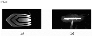
- FIG. 5 is a photograph illustrating a light emitting operation of the multi-sided luminous lighting member 100 according to the exemplary embodiment of the present invention.
- FIG. 5A illustrates a light emitting form on the second light exit portion 23 in the case in which the bezel portion 60 illustrated in FIG. 4 is provided. As illustrated in FIG. 5A , it can be seen that the light, which is emitted in the form of surface light from the second light exit portion 23, is adjusted by the bezel portion 60, thereby finally implementing the light emitting form.
- FIG. 5B illustrates a light emitting form on the first light exit portion 22 of the light guide member 20. It can be seen that a uniform light emitting pattern is made as the irregularity of the light emitting pattern is mitigated by the concave-convex portion formed on the first light exit portion 22.
- the lighting member 100 it is possible to provide the multi-sided luminous lighting member that simultaneously implements the uniform linear light on the first light exit portion 22 and the surface light on the second light exit portion 23.
- the light-transmitting resin film of the light guide member 20 may be cut into an appropriate shape, thereby obtaining the light guide members 20 having various shapes and thicknesses.
- the light guide member 20 may be cut into various shapes including a rectilinear shape or a curved shape and may also be cut into a more complicated shape. Therefore, the light guide member 20 may be easily processed to be suitable for an interior/exterior structure of the automobile that generally has a complicated three-dimensional structure. In this case, there is an advantage in that mass-production suitability is excellent because no expensive process such as an injection molding process is required. Further, it is possible to allow automobile designers to broaden a range of lighting designs inside/outside the automobile in consideration of various decorative effects and visibility.
- a plate-shaped structure having a predetermined minimum thickness of 3 to 4 mm or more may be manufactured through the injection molding process, and there is a limitation in that the injection molding process cannot manufacture a structure in the form of a thin film. Therefore, with the use of the light guide film 20 obtained by cutting the light-transmitting resin film into an appropriate shape as described in the present invention, it is possible to overcome the limitation of the injection molding process and thus to implement the lighting member 100 including an ultra-slim linear light source with maximized visibility and decorative effects.
- the shape of the light guide member 20 may be defined by several cut surfaces (or edges) formed by being cut and separated from the light-transmitting resin film. At least one of the several cut surfaces of the light guide member 20 may be used as the first light exit portion 22, and at least one other cut surface opposite to the first light exit portion 22 among the plurality of cut surfaces may be used as the light incident portion 24.
- the lighting member 100 may include a drive module 50 connected to the mounting board 40 or implemented on the mounting board 40 and configured to electrically operate the one or more light emitting diodes 30.
- the drive module 50 and the mounting board 40 may be integrated or separately manufactured and then coupled.
- the driving module 50 may be made of the same board material as the mount board 40 or may be made of a board material different from a board material of the mount board 40.
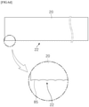
- FIGS. 6A to 6E illustrate the lighting members using the light guide members 20 with the various patterns formed on the first light exit portions 22 according to another exemplary embodiment of the present invention.
- the first light exit portion 22 is formed with a wave-shaped curved surface 82 in FIG. 6A , a triangular cut surface 83 in FIG. 6B , a continuously formed convex surface 84 in FIG. 6C , a continuously formed concave surface 85 in FIG. 6D , or an asymmetric triangular cut surface 20 similar to a serrated shape in FIG. 6E .
- the pattern structure on the surface of the first light exit portion 22 may be implemented during a process of cutting the light-transmitting resin film or may be formed by a method such as polishing or laser cutting after the cutting process.
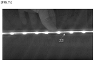
- FIGS. 7A to 7C are views for explaining a change in light emitting pattern in accordance with a pattern of the first light exit portion 22.
- the light incident portion 24 and the first light exit portion 22 of the light guide member 20 are opposite to each other, such that the light entering through the light incident portion 24 is provided to the first light exit portion 22 with high light-transmitting efficiency.
- this structure has a problem in that a light pattern made based on the arrangement of the light emitting diodes 30 is reflected directly on the light exit portion if the arrangement intervals between the light emitting diodes 30 are not very narrow.
- FIG. 7A is a photograph made by capturing a light emitting pattern observed at the first light exit portion 22 in the case in which the plurality of light emitting diodes 30 is disposed to be spaced apart from one another and the light incident portion 24 and the first light exit portion 22 are configured to have a flat surface without forming a pattern.
- light emitting spots made based on the arrangement positions of the multiple light emitting diodes 30 are reflected directly on the first light exit portion 22, and as a result, uniformity of the light emitting pattern is not good.
- a separate component such as a light diffusion plate needs to be used or the number of light emitting diodes needs to be increased so that the light emitting diodes are more densely arranged, which causes an increase in component costs.
- FIG. 7B is a photograph made by capturing a light emitting pattern observed at the first light exit portion 22 in the case in which a pattern is formed at the light incident portion 24 when the other structures as illustrated in FIG. 7A remain the same. Even in this case, like the case illustrated in FIG. 7A , light emitting spots made based on the arrangement positions of the multiple light emitting diodes 30 are reflected directly on the first light exit portion 22, and as a result, uniformity of the light emitting pattern is not good.
- FIG. 7C is a photograph made by capturing a light emitting pattern observed at the first light exit portion 22 in the case in which a pattern is formed on the light exit portion 24 when the other structures as illustrated in FIG. 7A remain the same.
- the light emitting spots made based on the arrangement positions of the multiple light emitting diodes 30 are rarely observed, and an ideal linear light source having an entirely and very uniform light emitting pattern may be implemented in a case in which the light emitting diodes 30 are not densely arranged.
- the pattern is formed on the first light exit portion 22 as described above, it is possible to obtain an effect of making a light emitting pattern uniform in a direction parallel to the light guide member 20 even though the light guide member 20 of the lighting member 100 has a thickness to some extent. Because this property is a property separate from flexibility of the light guide member 20, the light guide member 20 need not necessarily be obtained by the process of cutting the light-transmitting resin film, and a sheet or board, which is formed by a method such as injection molding like the related art, may be applied.
- a length from the light incident portion 24 to the first light exit portion 22 of the light guide member 20 is set to 8 mm to 250 mm, and as a result, it is possible to satisfy a technical standard (e.g., light amount, etc.) that needs to be satisfied by the lighting member, and it is possible to effectively implement uniformity of the light emitting pattern of the light guide member 20 in the case in which the lighting member to be provided in the automobile is implemented by using the light guide member 20 according to the exemplary embodiment of the present invention.
- a technical standard e.g., light amount, etc.
- the lighting member in a case in which a length of the light guide member 20 is set to 8 mm to 250 mm, it is possible to implement an ideal linear light source having an entirely and very uniform light emitting pattern at the first light exit portion 22 of the light guide member 20.
- FIGS. 8A and 8B illustrate a shape of the first light exit portion 22 of the light guide member 20 in which a plurality of patterns is repeatedly formed at predetermined intervals according to still another exemplary embodiment of the present invention.
- FIG. 8A illustrates (a) a case in which a pattern having a shape made by stacking a semicircle on a quadrangle is used, (b) a case in which a pattern having a shape made by stacking a triangle on a quadrangle is used, and (c) a case in which a pattern having a shape made by stacking a triangle on a semicircle is used.
- FIG. 8B illustrates (a) a case in which a pattern having a shape made by sequentially arranging a triangle, a semicircle, and a quadrangle is used, and (b) a case in which a pattern having a shape made by stacking a semicircle on a quadrangle, a shape made by stacking a triangle on a quadrangle, and a shape made by sequentially arranging a triangle and a quadrangle is used.
- FIGS. 9A to 9C illustrate the light guide members 20 having tapered cross sections and the lighting members using the light guide members 20 according to yet another exemplary embodiment of the present invention.
- the light guide member 20 having a uniform thickness (e.g., the light guide member 20 in FIG. 3 ) has been mainly described above as the exemplary embodiment of the present invention, but the present invention is not necessarily limited thereto, and the light guide member 20 according to the exemplary embodiment of the present invention may have a tapered cross section as illustrated in FIG. 9A .
- the thickness of the light guide member 20 having the uniform thickness cannot reach at least 3 to 4 mm, it is difficult to manufacture the light guide member 20 through the injection molding process.
- the light guide member 20 according to the exemplary embodiment of the present invention has the tapered cross section, it is possible to manufacture the light guide member 20 by using the injection molding process in the case in which the other side of the light guide member 20 has the large thickness (a + b) of 3 to 4 mm or more even though the thickness a of one side of the light guide member 20 cannot reach 3 to 4 mm.
- the light guide member 20 having the tapered cross section by applying the injection molding process and using an appropriate material such as acrylic-based resin (PMMA) or polycarbonate (PC).
- PMMA acrylic-based resin
- PC polycarbonate
- FIGS. 9B and 9C illustrate the lighting member 100 using the light guide member 20 having the tapered cross section according to the exemplary embodiment of the present invention.
- the light emitting diode 30, which may be employed in accordance with the thickness of the light guide member 20, may be limited in the case in which the light guide member 20 having the uniform thickness is used (e.g., a side-view light emitting diode (LED) is used to allow the light guide member 20 to have a thickness of 3 mm).
- the side-view light emitting diode (LED) may be used as illustrated in FIG. 9B
- a top-view light emitting diode (LED) may be easily employed as illustrated in FIG. 9C . Therefore, it is possible to obtain more excellent heat dissipation properties and light amount properties and to select the more inexpensive light emitting diode 30, such that it is possible to more effectively improve a performance of the lighting member 100.
- a coupling member (not illustrated) for fixing the light emitting diode 30, the mounting board 40, and the light guide member 20 may be provided.
- the light guide member 20 according to the exemplary embodiment of the present invention may have more various tapered cross sections.
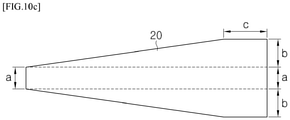
- FIGS. 10A to 10C illustrate the light guide members 20 having various tapered cross sections according to another exemplary embodiment of the present invention.
- an upper surface of the light guide member 20 may have a tapered shape as illustrated in FIG. 9A , or both of the upper and lower surfaces of the light guide member 20 may have tapered shapes as illustrated in FIG. 10A .
- the light guide member 20 may include a section having a uniform thickness (section c in FIGS. 10B and 10C ) in addition to the section having the tapered shape.
- the light guide member 20 may have various tapered cross sections, and as a result, it is possible to implement the lighting member 100 with the further improved structure and properties, and the light guide member 20 may be manufactured even by the injection molding process.
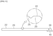
- FIG. 11 illustrates a pattern 25 formed on a surface of the second light exit portion 23 of the light guide member 20 according to the exemplary embodiment of the present invention. That is, as illustrated in FIG. 11 , the predetermined pattern 25 is formed on the surface of the second light exit portion 23, such that a part of the light, which enters the light incident portion 24 and travels toward the first light exit portion 22, exits the second light exit portion 23.
- the pattern 25 is formed on the surface of the second light exit portion 23 so that a brightness difference is made in a particular direction, such that a three-dimensional optical pattern may be more effectively formed.
- FIG. 11 illustrates that the triangular pattern is formed on the surface of the second light exit portion 23, but the present invention is not limited thereto, patterns having various shapes and sizes may be used.
- FIG. 12 is a photograph illustrating a structure and a light emitting operation of a three-dimensional lighting device implemented by arranging the plurality of lighting members 100 according to the exemplary embodiment of the present invention. More specifically, as illustrated in FIG. 12 , the three-dimensional lighting device according to the exemplary embodiment of the present invention is implemented by arranging the plurality of multi-sided luminous lighting members 100, thereby more effectively implementing the three-dimensional light emitting pattern.
- the three-dimensional lighting device further includes a control unit (not illustrated) capable of individually controlling and sequentially operating the plurality of arranged lighting members 100 or the light emitting diodes 30 included in the plurality of lighting members 100, thereby implementing the lighting device that may add patterns, which vary over time, to the three-dimensional light emitting pattern.
- a control unit capable of individually controlling and sequentially operating the plurality of arranged lighting members 100 or the light emitting diodes 30 included in the plurality of lighting members 100, thereby implementing the lighting device that may add patterns, which vary over time, to the three-dimensional light emitting pattern.
- FIG. 13 illustrates a light guide member 20 including a curved portion 26 according to the exemplary embodiment of the present invention. That is, as illustrated in FIG. 13 , the light guide member 20 may have various three-dimensional shapes as the light guide member 20 has the curved portion 26 which may be bent at a predetermined angle, such that it is possible to effectively implement the lighting member 100 having various three-dimensional light emitting patterns.
- a method of manufacturing the lighting member 100 includes: forming a light guide member 20 which is a light-transmitting light guide member 20 having a plurality of light emitting surfaces and has a light incident portion 24 which is at least one of the plurality of light emitting surfaces, a first light exit portion 22 which is at least one other light emitting surface opposite to the light incident portion 24 among the plurality of light emitting surfaces, and a second light exit portion 23 which is at least one other light emitting surface positioned laterally in a direction in which light entering the light incident portion 24 travels toward the first light exit portion 22, such that the first light exit portion 22 and the second light exit portion 23 emit the light that has entered the light incident portion 22; disposing the one or more light emitting diodes 30 on the mounting board 40 adjacent to the light incident portion 24 to allow the light to enter the light incident portion 24; coupling the light guide member 20 to the mounting board 40 having a surface on which the one or more light emitting diodes 30 is disposed; and connecting the drive module 50,
- the light guide member 20 may be formed by cutting and separating a flexible light-transmitting resin film or injection-molding light-transmitting resin.
Landscapes
- Engineering & Computer Science (AREA)
- Physics & Mathematics (AREA)
- General Engineering & Computer Science (AREA)
- Optics & Photonics (AREA)
- Microelectronics & Electronic Packaging (AREA)
- General Physics & Mathematics (AREA)
- Mechanical Engineering (AREA)
- Planar Illumination Modules (AREA)
Claims (13)
- Beleuchtungselement (100) umfassend:ein Lichtleiterelement (20), bei welchem es sich um ein mehrseitig lichtübertragendes Lichtleiterelement mit einer Mehrzahl von Oberflächen handelt und welches aufweist: einen Lichteinfallsabschnitt (24), der zumindest eine aus der Mehrzahl von Oberflächen darstellt, einen ersten Lichtaustrittsabschnitt (22), der zumindest eine andere Oberfläche aus der Mehrzahl von Oberflächen darstellt, die dem Lichteinfallsabschnitt (24) entgegengesetzt ist, und einen zweiten Lichtaustrittsabschnitt (23), der zumindest eine weitere Oberfläche darstellt, die in Bezug auf eine Richtung, in welcher Licht, das an dem Lichteinfallsabschnitt (24) eintritt und zu dem ersten Lichtaustrittsabschnitt (22) wandert, auf solche Weise seitwärtsgerichtet positioniert ist, dass das Licht, welches an dem Lichteinfallsabschnitt (24) eingetreten ist, von dem ersten Lichtaustrittsabschnitt (22) und von dem zweitem Lichtaustrittsabschnitt (23) abgegeben wird;eine Mehrzahl von lichtemittierenden Dioden (30), die in vorbestimmten Abständen benachbart zu dem Lichteinfallsabschnitt (24) angeordnet sind, um ein Eintreten des Lichts an dem Lichteinfallsabschnitt (24) zu erlauben; undeine Montageplatte (40), die mit dem Lichtleiterelement (20) verbunden ist und eine Oberfläche aufweist, auf welcher die Mehrzahl von lichtemittierenden Dioden (30) angeordnet ist,wobei ein konkav-konvexer Abschnitt auf einer Oberfläche des ersten Lichtaustrittsabschnitts (22) ausgebildet ist, um eine Unregelmäßigkeit eines Lichtemissionsmusters an dem ersten Lichtaustrittsabschnitt (22), die durch die Abstände zwischen den mehreren lichtemittierenden Dioden (30) an dem Lichteinfallsabschnitt (24) verursacht ist, abzuschwächen,wobei das Lichtleiterelement (20) einen Lichtleiterfilm umfasst, der Lichteinfallsabschnitt (24) eine Kantenfläche des Lichtleiterfilms umfasst, der erste Lichtaustrittsabschnitt (22) eine Linearlichtquelle implementiert und der zweite Lichtaustrittsabschnitt (22) eine Flächenlichtquelle implementiert,wobei ein vorbestimmtes Muster auf einer Oberfläche des zweiten Lichtaustrittsabschnitts (22) ausgebildet ist, um einen Teil des Lichts, das an dem Lichteinfallsabschnitt (24) eintritt und zu dem ersten Lichtaustrittsabschnitt (22) wandert, abzugeben,wobei die Linearlichtquelle und die Flächenlichtquelle das Licht zeitgleich abgeben.
- Beleuchtungselement nach Anspruch 1, wobei ein Muster an einer Oberfläche des zweiten Lichtaustrittsabschnitts (23) derart ausgebildet ist, dass ein Helligkeitsunterschied in einer bestimmten Richtung erzeugt wird.
- Beleuchtungselement nach Anspruch 1, weiterhin umfassend:einen Abschrägungsabschnitt (60), der an einer oberen oder unteren Oberfläche des Lichtleiterelements (20) angebracht ist,wobei durch den Abschrägungsabschnitt (60) ein Lichtemissionsmuster an dem zweiten Lichtaustrittsabschnitt unter Verwendung von Form und/oder Farbe und/oder Oberflächenbehandlungen angepasst wird.
- Beleuchtungselement nach Anspruch 3, wobei der Abschrägungsabschnitt (60) das Lichtleiterelement (20) und die Montageplatte (40) fixiert.
- Beleuchtungselement nach Anspruch 3, wobei der Abschrägungsabschnitt (60) eine reflektierende Oberfläche aufweist, die dafür ausgelegt ist, das an dem zweiten Lichtaustrittsabschnitt (23) austretende Licht zu reflektieren.
- Beleuchtungselement nach Anspruch 1, wobei der Lichteinfallsabschnitt (24) zu der Mehrzahl von lichtemittierenden Dioden (30) hinweist und der erste Lichtaustrittsabschnitt (22) in einer Ebene des Lichtleiterelements (20) auf einer Seite positioniert ist, die einer Seite des Lichteinfallsabschnitts (24) entgegengesetzt ist.
- Beleuchtungselement nach Anspruch 1, wobei konkavkonvexe Abschnitte mit einer oder zwei oder mehreren Formen sich in vorbestimmten Abständen wiederholend an der Oberfläche des ersten Lichtaustrittsabschnitts (22) angeordnet sind.
- Beleuchtungselement nach Anspruch 1, wobei sich eine Dicke des Lichtleiterfilms an einer Seite des ersten Lichtaustrittsabschnitts (22) und eine Dicke des Lichtleiterfilms an einer Seite des Lichteinfallsabschnitts (24) voneinander unterscheiden.
- Beleuchtungselement nach Anspruch 8, wobei der Lichtleiterfilm einen sich verjüngenden Querschnitt aufweist und eine Dicke des Lichtleiterfilms an einer Seite des ersten Lichtaustrittsabschnitts größer als eine Dicke des Lichtleiterfilms an einer Seite des Lichteinfallsabschnitts (24) ist.
- Beleuchtungselement nach Anspruch 1, wobei der Lichtleiterfilm einen in einem vorbestimmten Winkel gebogenen Krümmungsabschnitt umfasst.
- Dreidimensionale Beleuchtungsvorrichtung, welche ein dreidimensionales Lichtemissionsmuster implementiert, indem sie die Mehrzahl von Beleuchtungselementen (100) gemäß Anspruch 1 anordnet.
- Dreidimensionale Beleuchtungsvorrichtung nach Anspruch 11, ferner umfassend: eine Steuereinheit, die dafür ausgelegt ist, die Mehrzahl von zueinander angeordneten Beleuchtungselementen individuell anzusteuern und aufeinanderfolgend zu betätigen.
- Verfahren zur Herstellung eines Beleuchtungselements (100), wobei das Verfahren umfasst:das Ausbilden eines Lichtleiterelements (20), bei welchem es sich um ein mehrseitig lichtübertragendes Lichtleiterelement mit einer Mehrzahl von Oberflächen handelt und welches aufweist: einen Lichteinfallsabschnitt (24), der zumindest eine aus der Mehrzahl von Oberflächen darstellt, einen ersten Lichtaustrittsabschnitt (22), der zumindest eine andere Oberfläche aus der Mehrzahl von Oberflächen darstellt, die dem Lichteinfallsabschnitt (24) entgegengesetzt ist, und einen zweiten Lichtaustrittsabschnitt (23), der zumindest eine weitere Oberfläche darstellt, die in Bezug auf eine Richtung, in welcher Licht, das an dem Lichteinfallsabschnitt (24) eintritt und zu dem ersten Lichtaustrittsabschnitt (22) wandert, auf solche Weise seitwärtsgerichtet positioniert ist, dass das Licht, welches an dem Lichteinfallsabschnitt eingetreten ist, von dem ersten Lichtaustrittsabschnitt (22) und von dem zweitem Lichtaustrittsabschnitt (23) abgegeben wird;das Anordnen einer Mehrzahl von lichtemittierenden Dioden (30) in vorbestimmten Abständen an einer Montageplatte benachbart zu dem Lichteinfallsabschnitt (24), um ein Eintreten des Lichts an dem Lichteinfallsabschnitt (24) zu erlauben;das Koppeln des Lichtleiterelements (20) mit der Montageplatte (40), die eine Oberfläche aufweist, auf welcher die Mehrzahl von lichtemittierenden Dioden (30) angeordnet ist; unddas Verbinden der Montageplatte (40) mit einem Antriebsmodul (50), welches dafür ausgelegt ist, die Mehrzahl von lichtemittierenden Dioden (30) elektrisch zu betätigen,wobei ein konkav-konvexer Abschnitt auf einer Oberfläche des ersten Lichtaustrittsabschnitts (22) ausgebildet ist, um eine Unregelmäßigkeit eines Lichtemissionsmusters an dem ersten Lichtaustrittsabschnitt (22), die durch die Abstände zwischen den mehreren lichtemittierenden Dioden an dem Lichteinfallsabschnitt (24) verursacht ist, abzuschwächen,wobei das Lichtleiterelement einen Lichtleiterfilm umfasst, der Lichteinfallsabschnitt (24) eine Kantenfläche des Lichtleiterfilms umfasst, der erste Lichtaustrittsabschnitt eine Linearlichtquelle implementiert und der zweite Lichtaustrittsabschnitt (23) eine Flächenlichtquelle implementiert,wobei ein vorbestimmtes Muster auf einer Oberfläche des zweiten Lichtaustrittsabschnitts (23) ausgebildet wird, um einen Teil des Lichts, das an dem Lichteinfallsabschnitt (24) eintritt und zu dem ersten Lichtaustrittsabschnitt wandert, abzugeben,wobei die Linearlichtquelle und die Flächenlichtquelle das Licht zeitgleich abgeben.
Applications Claiming Priority (2)
| Application Number | Priority Date | Filing Date | Title |
|---|---|---|---|
| KR1020170088351A KR101850063B1 (ko) | 2017-07-12 | 2017-07-12 | 다면 발광 조명용 부재 및 이를 이용한 입체형 조명 장치 |
| PCT/KR2018/007397 WO2019013479A1 (ko) | 2017-07-12 | 2018-06-29 | 다면 발광 조명용 부재 및 이를 이용한 입체형 조명 장치 |
Publications (3)
| Publication Number | Publication Date |
|---|---|
| EP3608582A1 EP3608582A1 (de) | 2020-02-12 |
| EP3608582A4 EP3608582A4 (de) | 2020-05-13 |
| EP3608582B1 true EP3608582B1 (de) | 2022-02-09 |
Family
ID=62087785
Family Applications (1)
| Application Number | Title | Priority Date | Filing Date |
|---|---|---|---|
| EP18832391.9A Active EP3608582B1 (de) | 2017-07-12 | 2018-06-29 | Mehrseitiges leuchtelement und dasselbe verwendende dreidimensionale beleuchtungsvorrichtung |
Country Status (5)
| Country | Link |
|---|---|
| US (1) | US10969081B2 (de) |
| EP (1) | EP3608582B1 (de) |
| KR (1) | KR101850063B1 (de) |
| CN (1) | CN110914587A (de) |
| WO (1) | WO2019013479A1 (de) |
Families Citing this family (4)
| Publication number | Priority date | Publication date | Assignee | Title |
|---|---|---|---|---|
| KR20200080931A (ko) * | 2018-12-27 | 2020-07-07 | 에스엘 주식회사 | 차량용 램프 |
| CN112709968A (zh) * | 2021-01-14 | 2021-04-27 | 华域视觉科技(上海)有限公司 | 一种车辆信号灯光导结构和车辆 |
| CN116293510A (zh) * | 2021-12-21 | 2023-06-23 | 常州星宇车灯股份有限公司 | 立体光导装置、光学系统及车灯 |
| DE102022129705A1 (de) * | 2022-11-10 | 2024-05-16 | HELLA GmbH & Co. KGaA | Beleuchtungsvorrichtung für ein Kraftfahrzeug |
Family Cites Families (18)
| Publication number | Priority date | Publication date | Assignee | Title |
|---|---|---|---|---|
| JP3984023B2 (ja) * | 2001-11-02 | 2007-09-26 | 株式会社小糸製作所 | 車輌用灯具 |
| WO2005047884A1 (ja) | 2003-10-24 | 2005-05-26 | Wako Pure Chemical Industries, Ltd. | 高感度分析用溶媒及びその保存方法 |
| JP2005158362A (ja) * | 2003-11-21 | 2005-06-16 | Stanley Electric Co Ltd | 車両用灯具 |
| KR101460813B1 (ko) | 2006-09-29 | 2014-11-11 | 오스람 옵토 세미컨덕터스 게엠베하 | 유기 발광 소자 및 조명 장치 |
| JP4588729B2 (ja) * | 2007-02-16 | 2010-12-01 | ライツ・アドバンスト・テクノロジー株式会社 | 平面照明装置 |
| KR101345384B1 (ko) | 2007-11-16 | 2013-12-24 | 삼성전자주식회사 | 도광 부재와 이를 적용한 조명장치 및 도광 부재의제조방법 |
| JP2009224314A (ja) * | 2008-02-19 | 2009-10-01 | Citizen Electronics Co Ltd | 面状導光体及び電子機器 |
| KR200444467Y1 (ko) * | 2008-04-10 | 2009-05-14 | 세현유리제경(주) | 발광 유리판 |
| KR101597335B1 (ko) | 2008-11-17 | 2016-02-24 | 삼성디스플레이 주식회사 | 가요성 도광필름을 이용하는 백라이트 어셈블리 및 이를 포함하는 액정표시모듈 |
| EP2464996A1 (de) | 2009-08-12 | 2012-06-20 | 3M Innovative Properties Company | Lichtleiter |
| KR20110050819A (ko) * | 2009-11-09 | 2011-05-17 | 현대자동차주식회사 | 차량용 램프의 라이트 가이드 유닛 |
| DE102010061210A1 (de) | 2010-12-14 | 2012-06-14 | Hella Kgaa Hueck & Co. | Leuchte für Fahrzeuge |
| US8820992B2 (en) * | 2012-05-23 | 2014-09-02 | Ford Global Technologies, Llc | Automotive headlamp assembly |
| US9568662B2 (en) * | 2013-03-15 | 2017-02-14 | Cree, Inc. | Optical waveguide body |
| KR101484115B1 (ko) | 2014-10-23 | 2015-01-21 | 서규선 | Led를 이용한 감속감응형 차량용 보조 브레이크등 |
| KR101755866B1 (ko) * | 2015-10-23 | 2017-07-10 | 현대자동차주식회사 | 차량용 램프의 광원모듈 |
| KR101790044B1 (ko) | 2015-12-18 | 2017-10-25 | 현대아이에이치엘 주식회사 | 자동차의 조명장치 |
| FR3070070A1 (fr) * | 2017-08-14 | 2019-02-15 | Koito Manufacturing Co., Ltd. | Guide de lumiere en forme de tige et lampe de vehicule |
-
2017
- 2017-07-12 KR KR1020170088351A patent/KR101850063B1/ko active Active
-
2018
- 2018-06-29 US US16/615,312 patent/US10969081B2/en active Active
- 2018-06-29 EP EP18832391.9A patent/EP3608582B1/de active Active
- 2018-06-29 CN CN201880028959.2A patent/CN110914587A/zh not_active Withdrawn
- 2018-06-29 WO PCT/KR2018/007397 patent/WO2019013479A1/ko not_active Ceased
Also Published As
| Publication number | Publication date |
|---|---|
| US20200173626A1 (en) | 2020-06-04 |
| US10969081B2 (en) | 2021-04-06 |
| CN110914587A (zh) | 2020-03-24 |
| EP3608582A4 (de) | 2020-05-13 |
| WO2019013479A1 (ko) | 2019-01-17 |
| KR101850063B1 (ko) | 2018-04-19 |
| EP3608582A1 (de) | 2020-02-12 |
Similar Documents
| Publication | Publication Date | Title |
|---|---|---|
| US9903999B2 (en) | Light assembly for illuminating an emblem | |
| US9121565B2 (en) | Automotive lighting unit | |
| EP2548769B1 (de) | Rücklicht für ein Automobil | |
| US10969081B2 (en) | Multi-sided luminous lighting member and three-dimensional lighting device using same | |
| US10823903B2 (en) | Lighting member using light-guiding film | |
| CN103155020B (zh) | 面状发光装置 | |
| US11293621B2 (en) | Light guide for lamps and related lamp for motor vehicles | |
| KR20200080105A (ko) | Led 차량용 선형 발광 모듈 | |
| US9927087B1 (en) | Fiber optic light panel having a light enhancing element | |
| CN218510787U (zh) | 光学组件、照明装置及机动车辆 | |
| KR20140078372A (ko) | 차량용 면조명 | |
| US12571514B2 (en) | Lighting device for a motor vehicle | |
| CN117906093A (zh) | 用于车辆的照明装置 | |
| CN116336415A (zh) | 光学元件、照明装置及机动车辆 | |
| CN207880719U (zh) | 具有灯具的车用窗户 | |
| CN220688848U (zh) | 光学组件、照明装置及车辆 | |
| CN219318275U (zh) | 光学系统及具有该光学系统的车灯 | |
| KR20160093148A (ko) | 압출도광판을 적용한 측면조광형 아웃사이드미러의 방향지시등 | |
| CN122062216A (en) | Lighting device for a motor vehicle | |
| JP2013178995A (ja) | 車両用灯具 |
Legal Events
| Date | Code | Title | Description |
|---|---|---|---|
| STAA | Information on the status of an ep patent application or granted ep patent |
Free format text: STATUS: THE INTERNATIONAL PUBLICATION HAS BEEN MADE |
|
| PUAI | Public reference made under article 153(3) epc to a published international application that has entered the european phase |
Free format text: ORIGINAL CODE: 0009012 |
|
| STAA | Information on the status of an ep patent application or granted ep patent |
Free format text: STATUS: REQUEST FOR EXAMINATION WAS MADE |
|
| 17P | Request for examination filed |
Effective date: 20191107 |
|
| AK | Designated contracting states |
Kind code of ref document: A1 Designated state(s): AL AT BE BG CH CY CZ DE DK EE ES FI FR GB GR HR HU IE IS IT LI LT LU LV MC MK MT NL NO PL PT RO RS SE SI SK SM TR |
|
| AX | Request for extension of the european patent |
Extension state: BA ME |
|
| A4 | Supplementary search report drawn up and despatched |
Effective date: 20200409 |
|
| RIC1 | Information provided on ipc code assigned before grant |
Ipc: B60Q 1/26 20060101ALI20200403BHEP Ipc: F21K 9/61 20160101ALI20200403BHEP Ipc: G02B 5/02 20060101ALI20200403BHEP Ipc: F21Y 115/10 20160101ALI20200403BHEP Ipc: F21S 41/24 20180101ALI20200403BHEP Ipc: F21K 9/20 20160101AFI20200403BHEP Ipc: F21Y 105/10 20160101ALI20200403BHEP Ipc: F21V 8/00 20060101ALI20200403BHEP Ipc: F21S 41/30 20180101ALI20200403BHEP Ipc: F21S 43/235 20180101ALI20200403BHEP Ipc: F21Y 113/13 20160101ALI20200403BHEP |
|
| DAV | Request for validation of the european patent (deleted) | ||
| DAX | Request for extension of the european patent (deleted) | ||
| RIC1 | Information provided on ipc code assigned before grant |
Ipc: F21S 41/30 20180101ALI20210228BHEP Ipc: F21S 43/235 20180101ALI20210228BHEP Ipc: F21V 8/00 20060101ALI20210228BHEP Ipc: F21Y 105/10 20160101ALI20210228BHEP Ipc: F21S 41/24 20180101ALI20210228BHEP Ipc: B60Q 1/26 20060101ALI20210228BHEP Ipc: G02B 5/02 20060101ALI20210228BHEP Ipc: F21Y 115/10 20160101ALI20210228BHEP Ipc: F21K 9/20 20160101AFI20210228BHEP Ipc: F21K 9/61 20160101ALI20210228BHEP Ipc: F21Y 113/13 20160101ALI20210228BHEP |
|
| GRAP | Despatch of communication of intention to grant a patent |
Free format text: ORIGINAL CODE: EPIDOSNIGR1 |
|
| STAA | Information on the status of an ep patent application or granted ep patent |
Free format text: STATUS: GRANT OF PATENT IS INTENDED |
|
| INTG | Intention to grant announced |
Effective date: 20210830 |
|
| GRAS | Grant fee paid |
Free format text: ORIGINAL CODE: EPIDOSNIGR3 |
|
| GRAA | (expected) grant |
Free format text: ORIGINAL CODE: 0009210 |
|
| STAA | Information on the status of an ep patent application or granted ep patent |
Free format text: STATUS: THE PATENT HAS BEEN GRANTED |
|
| AK | Designated contracting states |
Kind code of ref document: B1 Designated state(s): AL AT BE BG CH CY CZ DE DK EE ES FI FR GB GR HR HU IE IS IT LI LT LU LV MC MK MT NL NO PL PT RO RS SE SI SK SM TR |
|
| REG | Reference to a national code |
Ref country code: GB Ref legal event code: FG4D |
|
| REG | Reference to a national code |
Ref country code: CH Ref legal event code: EP Ref country code: AT Ref legal event code: REF Ref document number: 1467721 Country of ref document: AT Kind code of ref document: T Effective date: 20220215 |
|
| REG | Reference to a national code |
Ref country code: IE Ref legal event code: FG4D |
|
| REG | Reference to a national code |
Ref country code: DE Ref legal event code: R096 Ref document number: 602018030704 Country of ref document: DE |
|
| REG | Reference to a national code |
Ref country code: LT Ref legal event code: MG9D |
|
| REG | Reference to a national code |
Ref country code: NL Ref legal event code: MP Effective date: 20220209 |
|
| REG | Reference to a national code |
Ref country code: AT Ref legal event code: MK05 Ref document number: 1467721 Country of ref document: AT Kind code of ref document: T Effective date: 20220209 |
|
| PG25 | Lapsed in a contracting state [announced via postgrant information from national office to epo] |
Ref country code: SE Free format text: LAPSE BECAUSE OF FAILURE TO SUBMIT A TRANSLATION OF THE DESCRIPTION OR TO PAY THE FEE WITHIN THE PRESCRIBED TIME-LIMIT Effective date: 20220209 Ref country code: RS Free format text: LAPSE BECAUSE OF FAILURE TO SUBMIT A TRANSLATION OF THE DESCRIPTION OR TO PAY THE FEE WITHIN THE PRESCRIBED TIME-LIMIT Effective date: 20220209 Ref country code: PT Free format text: LAPSE BECAUSE OF FAILURE TO SUBMIT A TRANSLATION OF THE DESCRIPTION OR TO PAY THE FEE WITHIN THE PRESCRIBED TIME-LIMIT Effective date: 20220609 Ref country code: NO Free format text: LAPSE BECAUSE OF FAILURE TO SUBMIT A TRANSLATION OF THE DESCRIPTION OR TO PAY THE FEE WITHIN THE PRESCRIBED TIME-LIMIT Effective date: 20220509 Ref country code: NL Free format text: LAPSE BECAUSE OF FAILURE TO SUBMIT A TRANSLATION OF THE DESCRIPTION OR TO PAY THE FEE WITHIN THE PRESCRIBED TIME-LIMIT Effective date: 20220209 Ref country code: LT Free format text: LAPSE BECAUSE OF FAILURE TO SUBMIT A TRANSLATION OF THE DESCRIPTION OR TO PAY THE FEE WITHIN THE PRESCRIBED TIME-LIMIT Effective date: 20220209 Ref country code: HR Free format text: LAPSE BECAUSE OF FAILURE TO SUBMIT A TRANSLATION OF THE DESCRIPTION OR TO PAY THE FEE WITHIN THE PRESCRIBED TIME-LIMIT Effective date: 20220209 Ref country code: ES Free format text: LAPSE BECAUSE OF FAILURE TO SUBMIT A TRANSLATION OF THE DESCRIPTION OR TO PAY THE FEE WITHIN THE PRESCRIBED TIME-LIMIT Effective date: 20220209 Ref country code: BG Free format text: LAPSE BECAUSE OF FAILURE TO SUBMIT A TRANSLATION OF THE DESCRIPTION OR TO PAY THE FEE WITHIN THE PRESCRIBED TIME-LIMIT Effective date: 20220509 |
|
| PG25 | Lapsed in a contracting state [announced via postgrant information from national office to epo] |
Ref country code: PL Free format text: LAPSE BECAUSE OF FAILURE TO SUBMIT A TRANSLATION OF THE DESCRIPTION OR TO PAY THE FEE WITHIN THE PRESCRIBED TIME-LIMIT Effective date: 20220209 Ref country code: LV Free format text: LAPSE BECAUSE OF FAILURE TO SUBMIT A TRANSLATION OF THE DESCRIPTION OR TO PAY THE FEE WITHIN THE PRESCRIBED TIME-LIMIT Effective date: 20220209 Ref country code: GR Free format text: LAPSE BECAUSE OF FAILURE TO SUBMIT A TRANSLATION OF THE DESCRIPTION OR TO PAY THE FEE WITHIN THE PRESCRIBED TIME-LIMIT Effective date: 20220510 Ref country code: FI Free format text: LAPSE BECAUSE OF FAILURE TO SUBMIT A TRANSLATION OF THE DESCRIPTION OR TO PAY THE FEE WITHIN THE PRESCRIBED TIME-LIMIT Effective date: 20220209 Ref country code: AT Free format text: LAPSE BECAUSE OF FAILURE TO SUBMIT A TRANSLATION OF THE DESCRIPTION OR TO PAY THE FEE WITHIN THE PRESCRIBED TIME-LIMIT Effective date: 20220209 |
|
| PG25 | Lapsed in a contracting state [announced via postgrant information from national office to epo] |
Ref country code: IS Free format text: LAPSE BECAUSE OF FAILURE TO SUBMIT A TRANSLATION OF THE DESCRIPTION OR TO PAY THE FEE WITHIN THE PRESCRIBED TIME-LIMIT Effective date: 20220609 |
|
| PG25 | Lapsed in a contracting state [announced via postgrant information from national office to epo] |
Ref country code: SM Free format text: LAPSE BECAUSE OF FAILURE TO SUBMIT A TRANSLATION OF THE DESCRIPTION OR TO PAY THE FEE WITHIN THE PRESCRIBED TIME-LIMIT Effective date: 20220209 Ref country code: SK Free format text: LAPSE BECAUSE OF FAILURE TO SUBMIT A TRANSLATION OF THE DESCRIPTION OR TO PAY THE FEE WITHIN THE PRESCRIBED TIME-LIMIT Effective date: 20220209 Ref country code: RO Free format text: LAPSE BECAUSE OF FAILURE TO SUBMIT A TRANSLATION OF THE DESCRIPTION OR TO PAY THE FEE WITHIN THE PRESCRIBED TIME-LIMIT Effective date: 20220209 Ref country code: EE Free format text: LAPSE BECAUSE OF FAILURE TO SUBMIT A TRANSLATION OF THE DESCRIPTION OR TO PAY THE FEE WITHIN THE PRESCRIBED TIME-LIMIT Effective date: 20220209 Ref country code: DK Free format text: LAPSE BECAUSE OF FAILURE TO SUBMIT A TRANSLATION OF THE DESCRIPTION OR TO PAY THE FEE WITHIN THE PRESCRIBED TIME-LIMIT Effective date: 20220209 Ref country code: CZ Free format text: LAPSE BECAUSE OF FAILURE TO SUBMIT A TRANSLATION OF THE DESCRIPTION OR TO PAY THE FEE WITHIN THE PRESCRIBED TIME-LIMIT Effective date: 20220209 |
|
| REG | Reference to a national code |
Ref country code: DE Ref legal event code: R097 Ref document number: 602018030704 Country of ref document: DE |
|
| PG25 | Lapsed in a contracting state [announced via postgrant information from national office to epo] |
Ref country code: AL Free format text: LAPSE BECAUSE OF FAILURE TO SUBMIT A TRANSLATION OF THE DESCRIPTION OR TO PAY THE FEE WITHIN THE PRESCRIBED TIME-LIMIT Effective date: 20220209 |
|
| PLBE | No opposition filed within time limit |
Free format text: ORIGINAL CODE: 0009261 |
|
| STAA | Information on the status of an ep patent application or granted ep patent |
Free format text: STATUS: NO OPPOSITION FILED WITHIN TIME LIMIT |
|
| 26N | No opposition filed |
Effective date: 20221110 |
|
| PG25 | Lapsed in a contracting state [announced via postgrant information from national office to epo] |
Ref country code: MC Free format text: LAPSE BECAUSE OF FAILURE TO SUBMIT A TRANSLATION OF THE DESCRIPTION OR TO PAY THE FEE WITHIN THE PRESCRIBED TIME-LIMIT Effective date: 20220209 |
|
| REG | Reference to a national code |
Ref country code: CH Ref legal event code: PL |
|
| REG | Reference to a national code |
Ref country code: BE Ref legal event code: MM Effective date: 20220630 |
|
| PG25 | Lapsed in a contracting state [announced via postgrant information from national office to epo] |
Ref country code: SI Free format text: LAPSE BECAUSE OF FAILURE TO SUBMIT A TRANSLATION OF THE DESCRIPTION OR TO PAY THE FEE WITHIN THE PRESCRIBED TIME-LIMIT Effective date: 20220209 |
|
| GBPC | Gb: european patent ceased through non-payment of renewal fee |
Effective date: 20220629 |
|
| PG25 | Lapsed in a contracting state [announced via postgrant information from national office to epo] |
Ref country code: LU Free format text: LAPSE BECAUSE OF NON-PAYMENT OF DUE FEES Effective date: 20220629 Ref country code: LI Free format text: LAPSE BECAUSE OF NON-PAYMENT OF DUE FEES Effective date: 20220630 Ref country code: IE Free format text: LAPSE BECAUSE OF NON-PAYMENT OF DUE FEES Effective date: 20220629 Ref country code: FR Free format text: LAPSE BECAUSE OF NON-PAYMENT OF DUE FEES Effective date: 20220630 Ref country code: CH Free format text: LAPSE BECAUSE OF NON-PAYMENT OF DUE FEES Effective date: 20220630 |
|
| PG25 | Lapsed in a contracting state [announced via postgrant information from national office to epo] |
Ref country code: GB Free format text: LAPSE BECAUSE OF NON-PAYMENT OF DUE FEES Effective date: 20220629 Ref country code: BE Free format text: LAPSE BECAUSE OF NON-PAYMENT OF DUE FEES Effective date: 20220630 |
|
| PG25 | Lapsed in a contracting state [announced via postgrant information from national office to epo] |
Ref country code: IT Free format text: LAPSE BECAUSE OF FAILURE TO SUBMIT A TRANSLATION OF THE DESCRIPTION OR TO PAY THE FEE WITHIN THE PRESCRIBED TIME-LIMIT Effective date: 20220209 |
|
| PG25 | Lapsed in a contracting state [announced via postgrant information from national office to epo] |
Ref country code: MK Free format text: LAPSE BECAUSE OF FAILURE TO SUBMIT A TRANSLATION OF THE DESCRIPTION OR TO PAY THE FEE WITHIN THE PRESCRIBED TIME-LIMIT Effective date: 20220209 Ref country code: CY Free format text: LAPSE BECAUSE OF FAILURE TO SUBMIT A TRANSLATION OF THE DESCRIPTION OR TO PAY THE FEE WITHIN THE PRESCRIBED TIME-LIMIT Effective date: 20220209 |
|
| PG25 | Lapsed in a contracting state [announced via postgrant information from national office to epo] |
Ref country code: HU Free format text: LAPSE BECAUSE OF FAILURE TO SUBMIT A TRANSLATION OF THE DESCRIPTION OR TO PAY THE FEE WITHIN THE PRESCRIBED TIME-LIMIT; INVALID AB INITIO Effective date: 20180629 |
|
| PG25 | Lapsed in a contracting state [announced via postgrant information from national office to epo] |
Ref country code: MT Free format text: LAPSE BECAUSE OF FAILURE TO SUBMIT A TRANSLATION OF THE DESCRIPTION OR TO PAY THE FEE WITHIN THE PRESCRIBED TIME-LIMIT Effective date: 20220209 |
|
| PGFP | Annual fee paid to national office [announced via postgrant information from national office to epo] |
Ref country code: DE Payment date: 20250626 Year of fee payment: 8 |
|
| PG25 | Lapsed in a contracting state [announced via postgrant information from national office to epo] |
Ref country code: TR Free format text: LAPSE BECAUSE OF FAILURE TO SUBMIT A TRANSLATION OF THE DESCRIPTION OR TO PAY THE FEE WITHIN THE PRESCRIBED TIME-LIMIT Effective date: 20220209 |