EP3608653A1 - Vorrichtung und verfahren zur messung der teilchengrösse mittels rückgestreutem licht - Google Patents
Vorrichtung und verfahren zur messung der teilchengrösse mittels rückgestreutem licht Download PDFInfo
- Publication number
- EP3608653A1 EP3608653A1 EP18187526.1A EP18187526A EP3608653A1 EP 3608653 A1 EP3608653 A1 EP 3608653A1 EP 18187526 A EP18187526 A EP 18187526A EP 3608653 A1 EP3608653 A1 EP 3608653A1
- Authority
- EP
- European Patent Office
- Prior art keywords
- particle
- optical axis
- lens
- light
- detector
- Prior art date
- Legal status (The legal status is an assumption and is not a legal conclusion. Google has not performed a legal analysis and makes no representation as to the accuracy of the status listed.)
- Granted
Links
Images




Classifications
-
- G—PHYSICS
- G01—MEASURING; TESTING
- G01N—INVESTIGATING OR ANALYSING MATERIALS BY DETERMINING THEIR CHEMICAL OR PHYSICAL PROPERTIES
- G01N15/00—Investigating characteristics of particles; Investigating permeability, pore-volume or surface-area of porous materials
- G01N15/10—Investigating individual particles
- G01N15/14—Optical investigation techniques, e.g. flow cytometry
- G01N15/1456—Optical investigation techniques, e.g. flow cytometry without spatial resolution of the texture or inner structure of the particle, e.g. processing of pulse signals
-
- G—PHYSICS
- G01—MEASURING; TESTING
- G01N—INVESTIGATING OR ANALYSING MATERIALS BY DETERMINING THEIR CHEMICAL OR PHYSICAL PROPERTIES
- G01N15/00—Investigating characteristics of particles; Investigating permeability, pore-volume or surface-area of porous materials
- G01N15/10—Investigating individual particles
- G01N15/14—Optical investigation techniques, e.g. flow cytometry
- G01N15/1434—Optical arrangements
-
- G—PHYSICS
- G01—MEASURING; TESTING
- G01N—INVESTIGATING OR ANALYSING MATERIALS BY DETERMINING THEIR CHEMICAL OR PHYSICAL PROPERTIES
- G01N15/00—Investigating characteristics of particles; Investigating permeability, pore-volume or surface-area of porous materials
- G01N2015/0023—Investigating dispersion of liquids
- G01N2015/0026—Investigating dispersion of liquids in gas, e.g. fog
-
- G—PHYSICS
- G01—MEASURING; TESTING
- G01N—INVESTIGATING OR ANALYSING MATERIALS BY DETERMINING THEIR CHEMICAL OR PHYSICAL PROPERTIES
- G01N15/00—Investigating characteristics of particles; Investigating permeability, pore-volume or surface-area of porous materials
- G01N2015/0042—Investigating dispersion of solids
- G01N2015/0046—Investigating dispersion of solids in gas, e.g. smoke
-
- G—PHYSICS
- G01—MEASURING; TESTING
- G01N—INVESTIGATING OR ANALYSING MATERIALS BY DETERMINING THEIR CHEMICAL OR PHYSICAL PROPERTIES
- G01N15/00—Investigating characteristics of particles; Investigating permeability, pore-volume or surface-area of porous materials
- G01N15/10—Investigating individual particles
- G01N15/14—Optical investigation techniques, e.g. flow cytometry
- G01N15/1434—Optical arrangements
- G01N2015/1454—Optical arrangements using phase shift or interference, e.g. for improving contrast
-
- G—PHYSICS
- G01—MEASURING; TESTING
- G01N—INVESTIGATING OR ANALYSING MATERIALS BY DETERMINING THEIR CHEMICAL OR PHYSICAL PROPERTIES
- G01N15/00—Investigating characteristics of particles; Investigating permeability, pore-volume or surface-area of porous materials
- G01N15/10—Investigating individual particles
- G01N15/14—Optical investigation techniques, e.g. flow cytometry
- G01N2015/1493—Particle size
-
- G—PHYSICS
- G01—MEASURING; TESTING
- G01N—INVESTIGATING OR ANALYSING MATERIALS BY DETERMINING THEIR CHEMICAL OR PHYSICAL PROPERTIES
- G01N15/00—Investigating characteristics of particles; Investigating permeability, pore-volume or surface-area of porous materials
- G01N15/10—Investigating individual particles
- G01N15/14—Optical investigation techniques, e.g. flow cytometry
- G01N2015/1497—Particle shape
Definitions
- the present invention relates to an apparatus and method to measure the size of particles using the angular intensity distribution of light scattered in the near backward direction.
- the measurement of particle size is nowadays essential in many fields: application of pesticides in agriculture, characterization of ice and ash particles in atmospheric clouds, sizing of cement particles in building construction, etc.
- Optical methods based on light scattering benefit from their non-intrusive nature; therefore, many have been developed for measuring particle size.
- some widely used optical methods obtain the size of particles from the angular intensity distribution of the scattered light.
- These methods share the same basic principle.
- a light source is used to illuminate the particles, which scatter the light in all directions in space.
- the light scattered by the particles interferes producing an angular intensity distribution that is characteristic of its size and optical properties.
- a detector located at a certain angular position is then used to record an image of this intensity pattern.
- an algorithm is used to retrieve the particle size from this image.
- the light used to illuminate the particles needs to be collimated and have a certain degree of spatial coherence. Laser light is the most convenient, and therefore the most used, because of its high degree of coherence and high intensity, which allows to measure scattered light from smaller particles.
- a combination of lenses is used to create a thin laser sheet that illuminates an ensemble of spherical droplets.
- a camera records an out-of-focus image of the droplets at a scattering angle of 45°.
- Each droplet appears separately in the image as an elliptical disk in which interference fringes are visible. While the size and shape of the disk depend only on the camera aperture and the position of the droplet, the frequency of the fringes is proportional to the droplet diameter.
- Later improvements of the technique include the addition of a cylindrical lens in order to compress the out-of-focus image of the droplets; this is described by Maeda and Kawaguchi in the patent EP1162447 , and it allows to measure droplet size in sprays in which the droplet concentration is higher.
- the method proposed by van Beeck and Riethmuller employs the rainbow phenomena to obtain size and temperature of a spherical droplet.
- a laser beam is used to illuminate the droplet, and a digital camera is used to record the interference pattern produced by the droplet at the rainbow angle, at approximately 139°.
- the rainbow fringes are used to determine the size and temperature of the droplet by means of the Airy theory.
- This method can also be used to obtain the size distribution of an ensemble of droplets (as described by van Beeck et al. and Vetrano et al.).
- the laser beam is expanded in order to illuminate a bigger portion of the spray.
- the sensor of the camera is located in such a way that it images the focal plane of the collecting lens, so the interference pattern is independent of the position of the droplets. In this way, a global rainbow pattern is obtained and the size distribution of the illuminated droplets can be retrieved.
- the method described by Schmitz et al. in the patent EP0701707 can measure the size of spherical droplets and irregular particles.
- particle size is deduced from the diffraction pattern produced by the particles in the forward direction.
- a large number of individual photo detectors, located at multiple locations, are used to register the scattered light.
- an angular array is typically used, such as the one described by George et al. in the US patent 3,689,772 .
- the present invention employs the same principle as the methods previously described but, in this case, the detector registers the light that is scattered by the particles in the direction of the illumination source, i.e. in the near backward direction.
- the backscattered light has also been used to measure particle size by some existing devices which are described in: K. Beswick et al., 2014, Atmos. Meas. Tech., "The backscatter cloud probe - a compact low-profile autonomous optical spectrometer ". US patent 4,492,467, Drain et al. , " Measurement of the size of particles”. B. Mayer et al., 2004, Atmos. Chem. Phys. Discuss. , "Remote sensing of water cloud droplet size distributions using backscatter glory: a case study”.
- the device described by Beswick et al. employs a laser diode that produces linearly polarized light focused on a small region at 4 cm from the collecting optics.
- the light that is backscattered at an angle of 144-156° is collected into an avalanche photodiode, which transforms the scattered light into a voltage signal.
- This signal is related to the equivalent diameter of the particle by comparing the peak of intensity with the Lorenz-Mie theory.
- this device is advantageous for aeronautical applications due to its light weight and compact design, it presents several sources of error.
- the peak of backscattered light intensity does not increase monotonically with respect to the particle diameter.
- situations in which more than one particle crosses the probe volume, or in which the particle partially crosses the laser can produce errors in the measurements.
- the US patent 4,492,467 describes a device that measures the angular intensity distribution of the backscattered light.
- a quarter wave plate converts the incident plane polarized laser beam into a circularly polarized laser beam that illuminates the particles.
- a beam splitter redirects the backscattered light into a polarization analyzer, which leaves only the component of the scattered light that rotates in the opposite sense as the incident beam.
- Geometrical optics and diffraction theory are used to relate the positions of the intensity peaks found in this signal to the particle diameter.
- the detector consists in an annular arrangement of photo diodes or photomultipliers.
- the device proposed by Mayer et al. is intended to measure cloud droplet size distributions. It uses a push broom imaging spectrometer to record an image of the glory phenomenon with an angular field of view of 34°.
- the droplet size distribution of the cloud is related with the angular intensity distribution of the glory, and it is calculated by fitting the Lorenz-Mie theory in the experimental signal.
- this method is only valid for very small spherical droplets (in the order of a few micrometers) and it requires the presence of sunlight to operate.
- the objective of the present invention is to provide a compact apparatus and method to measure the size of particles from the angular intensity distribution of the backscattered light by using simple optical elements.
- particle used here refers both to spherical droplets and irregular particles.
- the particles to be measured by the invention must be larger than the wavelength of the incident light, and must have a refractive index that is different than the one of the surroundings.
- the invention also permits to characterize a particle as a droplet or as an irregular particle.
- the present invention includes an apparatus and method for measuring the size of droplets employing the angular intensity distribution of the backscattered light. It comprises a coherent light source, an optical system to collect the backscattered light, a detector and means to calculate the size of the particles from the signal recorded in the detector.
- the light source may be a laser, either continuous or pulsed, a laser diode or another source of coherent light capable of producing a collimated beam.
- the laser beam should be bigger than the particle diameter but small enough to ensure a small sample volume.
- a small mirror located next to the collecting lens is used to reflect the laser beam in the direction of the particles.
- the optical system comprises a first lens that collects the backscattered light, a pinhole located at the image plane of the probe volume and a second lens that converges the light into the detector.
- the size of the pinhole determines the size of the sample volume.
- the detector records the out-of-focus image of the particles, where the angular distribution of the scattered light intensity is measured.
- a post-processor uses the angular frequency contained in this intensity pattern to obtain the size of the particles.
- this method comprises the steps of
- light that is scattered back by the particle is collected by means of a first lens aligned on said optical axis such that said out-of-focus image is formed in a focal plane of this first lens.
- said out-of-focus image is projected onto a sensor element of said detector by means of a second lens.
- the method of the invention comprises setting a length of the sample volume along the optical axis by providing a pinhole with a defined aperture on said optical axis between said focal plane and the detector.
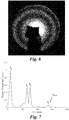
- said particle is characterized as a droplet when said intensity distribution pattern essentially comprises concentric circles or is characterized as an irregular particle when said intensity distribution pattern essentially comprises speckles.
- the invention also concerns a device for determining the size of a particle present in a sample volume.
- the apparatus comprises an illumination source, a number of optical elements to collect the backscattered light, and a detector.
- a schematic representation of the preferred embodiment of the invention is given in Figure 1a .
- the incident light beam 9 is reflected by a small mirror 7, which directs the beam in the direction of the particles along an optical axis 14 towards a probe volume or a sample volume 1 containing particles to be measured.
- the rest of the optical elements, as well as the detector, are aligned with said axis 14.
- the light 8 that is backscattered by the particles is collected by the lens 2 that is perpendicular to the axis 14.
- the plane 3 is the focal plane of lens 2. At this plane, all rays scattered by the particles at the same angle are focused into the same point. Therefore, the interference pattern that is formed in this plane is independent of the position of the particle along said optical axis 14.
- backscattered light is understood the light 8 that is returned by the particle in the direction of the impinging light beam 9 within an angle ⁇ of 1° to 15° with respect to the optical axis 14 as shown in Figs. 1a and 1b .
- a pinhole 4 is located between lenses 2 and 5 in order to select the length of the probe volume 1 along said optical axis 14.
- the lens 5 and the detector having a sensor 6 can be selected independently or it can be, for instance, a commercially available camera with a CCD or a CMOS sensor. They are located in such a way that the image of plane 3 is recorded in the detector.
- the incident light beam must be coherent, typically a laser.
- the beam diameter must be bigger than the biggest particle diameter but small enough to ensure a small sample volume.
- Other means of directing the incident light beam into the particles may be used instead of the small mirror, such as a beam splitter. Nevertheless, the small mirror proposed in the preferred embodiment is believed by the inventors to provide the best image quality.
- FIG. 1b The embodiment represented in Figure 1b is very similar to the one presented in Figure 1a , with the exception that, in this case, the mirror reflecting the incident illumination beam is located before lens 2. In this case, the illumination beam will be focused at a distance that will be determined by the focal length of lens 2. Therefore, the location of the pinhole 4 needs to be selected accordingly.
- the image obtained by the detector is different depending on the nature of the particle.
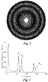
- the backscattered light intensity distribution in the image has the appearance of concentric rings.
- Figure 3 shows the Fourier Transform of the intensity distribution showed in Figure 2 .
- Several angular frequencies can be noted in Figure 3 .
- the peaks observed in this figure correspond to the interference between two different scattered light rays, and the frequency of the peak is proportional to the separation distance between these rays, and is related to the droplet diameter by geometrical equations.
- the system here described can be placed into a probe for laboratory or industrial use. It is understood that the parameters of the optical elements described before, such as focal length, distance, diameter, etc., can be modified to make the instrument as compact as needed.
- Some examples of an instrument probe are given in Figure 10a for the system described in Figure 1a , and in Figure 10b for the system described in Figure 1b .
- the numbers used to describe each element are kept the same throughout all the figures.
- the source of the illumination beam 11 and a processing element 12 have been added.
- an optical window 13 has been added in Figure 10a .
- the processing element 12 comprises, for example, a computer and permits to apply a Fourier transform onto said distribution pattern recorded by the detector. Further, this computer also has selecting means for identifying a maximum angular frequency (F max ) where said Fourier transform presents a peak.
- the computer comprises computing means.
- FIGS. 6 to 9 Two examples of size measurements performed with such a system are given in figures 6 to 9 . They were performed with a configuration as the one described in Figure 1a .
- a pulsed laser with a wavelength of 532 nm was used as an illuminating beam to measure the diameter of a water droplet.
- the backscattered light pattern corresponds to the concentric rings, and the Fourier analysis of these rings reveals different peaks. The last peak was used in this case to obtain the droplet diameter.
- a continuous wave laser with a wavelength of 632.8 nm was used to measure the particle size of a sand particle. A speckle pattern is observed in this case.
- a digital camera with a CMOS sensor was used as a detector.
- the processing element was a laptop with a Matlab code to do the calculations.
Landscapes
- Chemical & Material Sciences (AREA)
- Dispersion Chemistry (AREA)
- Physics & Mathematics (AREA)
- Health & Medical Sciences (AREA)
- Life Sciences & Earth Sciences (AREA)
- Analytical Chemistry (AREA)
- Biochemistry (AREA)
- General Health & Medical Sciences (AREA)
- General Physics & Mathematics (AREA)
- Immunology (AREA)
- Pathology (AREA)
- Investigating Or Analysing Materials By Optical Means (AREA)
- Length Measuring Devices By Optical Means (AREA)
Priority Applications (1)
| Application Number | Priority Date | Filing Date | Title |
|---|---|---|---|
| EP18187526.1A EP3608653B1 (de) | 2018-08-06 | 2018-08-06 | Vorrichtung und verfahren zur messung der teilchengrösse mittels rückgestreutem licht |
Applications Claiming Priority (1)
| Application Number | Priority Date | Filing Date | Title |
|---|---|---|---|
| EP18187526.1A EP3608653B1 (de) | 2018-08-06 | 2018-08-06 | Vorrichtung und verfahren zur messung der teilchengrösse mittels rückgestreutem licht |
Publications (2)
| Publication Number | Publication Date |
|---|---|
| EP3608653A1 true EP3608653A1 (de) | 2020-02-12 |
| EP3608653B1 EP3608653B1 (de) | 2024-03-13 |
Family
ID=63165282
Family Applications (1)
| Application Number | Title | Priority Date | Filing Date |
|---|---|---|---|
| EP18187526.1A Active EP3608653B1 (de) | 2018-08-06 | 2018-08-06 | Vorrichtung und verfahren zur messung der teilchengrösse mittels rückgestreutem licht |
Country Status (1)
| Country | Link |
|---|---|
| EP (1) | EP3608653B1 (de) |
Cited By (2)
| Publication number | Priority date | Publication date | Assignee | Title |
|---|---|---|---|---|
| CN112113514A (zh) * | 2020-09-22 | 2020-12-22 | 中国科学院长春光学精密机械与物理研究所 | 一种波前信息的检测方法、装置以及系统 |
| US20240198596A1 (en) * | 2022-12-15 | 2024-06-20 | Seurat Technologies, Inc. | Powder Bed Measurement For Additive Manufacturing |
Citations (6)
| Publication number | Priority date | Publication date | Assignee | Title |
|---|---|---|---|---|
| US3689772A (en) | 1971-08-18 | 1972-09-05 | Litton Systems Inc | Photodetector light pattern detector |
| US4492467A (en) | 1981-06-04 | 1985-01-08 | United Kingdom Atomic Energy Authority | Measurement of the size of particles |
| EP0701707A1 (de) | 1993-06-04 | 1996-03-20 | Coulter Corporation | Verfahren und vorrichtung zur messung der teilchengrössenverteilung unter verwendung von laserstreuung |
| EP1162447A1 (de) | 2000-01-07 | 2001-12-12 | Keio University | Verfahren und vorrichtung zur messung von durchmesser und verteilung von mikroblasen und mikroflüssigkeitstropfen und optisches system zur messung von durchmesser und verteilung von mikroblasen und mikroflüssigkeitstropfen |
| US20080218738A1 (en) * | 2004-04-10 | 2008-09-11 | Michael Trainer | Methods and apparatus for determining particle characteristics by measuring scattered light |
| US20170276613A1 (en) * | 2016-03-28 | 2017-09-28 | Kla-Tencor Corporation | Methods and apparatus for polarized wafer inspection |
-
2018
- 2018-08-06 EP EP18187526.1A patent/EP3608653B1/de active Active
Patent Citations (6)
| Publication number | Priority date | Publication date | Assignee | Title |
|---|---|---|---|---|
| US3689772A (en) | 1971-08-18 | 1972-09-05 | Litton Systems Inc | Photodetector light pattern detector |
| US4492467A (en) | 1981-06-04 | 1985-01-08 | United Kingdom Atomic Energy Authority | Measurement of the size of particles |
| EP0701707A1 (de) | 1993-06-04 | 1996-03-20 | Coulter Corporation | Verfahren und vorrichtung zur messung der teilchengrössenverteilung unter verwendung von laserstreuung |
| EP1162447A1 (de) | 2000-01-07 | 2001-12-12 | Keio University | Verfahren und vorrichtung zur messung von durchmesser und verteilung von mikroblasen und mikroflüssigkeitstropfen und optisches system zur messung von durchmesser und verteilung von mikroblasen und mikroflüssigkeitstropfen |
| US20080218738A1 (en) * | 2004-04-10 | 2008-09-11 | Michael Trainer | Methods and apparatus for determining particle characteristics by measuring scattered light |
| US20170276613A1 (en) * | 2016-03-28 | 2017-09-28 | Kla-Tencor Corporation | Methods and apparatus for polarized wafer inspection |
Non-Patent Citations (11)
| Title |
|---|
| A.R. GLOVER ET AL.: "Interferometric laser imaging for droplet sizing: a method for droplet-size measurement in sparse spray systems", APPL. OPT., 1995 |
| B. MAYER ET AL.: "Remote sensing of water cloud droplet size distributions using backscatter glory: a case study", ATMOS. CHEM. PHYS. DISCUSS., 2004 |
| GEORGE ET AL., PHOTODETECTOR LIGHT PATTERN DETECTOR |
| J. P. A. J. VAN BEECK; M. L. RIETHMULLER: "Method and apparatus for measuring diameter and distribution of micro bubble and micro liquid drop and optical system for measuring diameter and distribution of micro bubble and micro liquid drop", APPL. OPT., 1996 |
| J.P.A.J. VAN BEECK ET AL.: "Rainbow phenomena applied to the measurement of droplet size and velocity and to the detection of non-sphericity", OPT. LETT., 1999 |
| K. BESWICK ET AL.: "The backscatter cloud probe - a compact low-profile autonomous optical spectrometer", ATMOS. MEAS. TECH., 2014 |
| M. R. VETRANO ET AL.: "Global rainbow thermometry for droplet-temperature measurement", EXP. FLUIDS, 2006 |
| M. TALBI ET AL: "Interferometric particle imaging of ice particles using a multi-view optical system", APPLIED OPTICS, vol. 57, no. 21, 19 July 2018 (2018-07-19), US, pages 6188, XP055548342, ISSN: 1559-128X, DOI: 10.1364/AO.57.006188 * |
| PEDRO GARCÍA CARRASCAL ET AL: "Irregular particle sizing using speckle pattern for continuous wave laser applications", EXPERIMENTS IN FLUIDS., vol. 55, no. 11, 5 November 2014 (2014-11-05), DE, XP055548675, ISSN: 0723-4864, DOI: 10.1007/s00348-014-1851-0 * |
| SARA GONZÁLEZ RUIZ ET AL: "Feasibility of using glory and speckle patterns for sizing spherical and irregular particles", APPLIED OPTICS, OPTICAL SOCIETY OF AMERICA, WASHINGTON, DC; US, vol. 53, no. 21, 20 July 2014 (2014-07-20), pages 4722 - 4728, XP001590698, ISSN: 0003-6935, [retrieved on 20140717], DOI: 10.1364/AO.53.004722 * |
| SARA GONZÁLEZ RUIZ ET AL: "Sizing of sand and ash particles using their speckle pattern: influence of particle opacity", EXPERIMENTS IN FLUIDS., vol. 58, no. 8, 7 July 2017 (2017-07-07), DE, XP055548644, ISSN: 0723-4864, DOI: 10.1007/s00348-017-2384-0 * |
Cited By (3)
| Publication number | Priority date | Publication date | Assignee | Title |
|---|---|---|---|---|
| CN112113514A (zh) * | 2020-09-22 | 2020-12-22 | 中国科学院长春光学精密机械与物理研究所 | 一种波前信息的检测方法、装置以及系统 |
| CN112113514B (zh) * | 2020-09-22 | 2021-12-31 | 中国科学院长春光学精密机械与物理研究所 | 一种波前信息的检测方法、装置以及系统 |
| US20240198596A1 (en) * | 2022-12-15 | 2024-06-20 | Seurat Technologies, Inc. | Powder Bed Measurement For Additive Manufacturing |
Also Published As
| Publication number | Publication date |
|---|---|
| EP3608653B1 (de) | 2024-03-13 |
Similar Documents
| Publication | Publication Date | Title |
|---|---|---|
| Maeda et al. | Novel interferometric measurement of size and velocity distributions of spherical particles in fluid flows | |
| CN103868831B (zh) | 云粒子谱分布测量方法及测量系统 | |
| US4340306A (en) | Optical system for surface topography measurement | |
| US4387994A (en) | Optical system for surface topography measurement | |
| US6879708B2 (en) | Planar particle/droplet size measurement technique using digital particle image velocimetry image data | |
| CN103842797A (zh) | 一维全场彩虹测量装置及测量方法 | |
| Semidetnov et al. | Conversion relationships for multidimensional particle sizing techniques | |
| JPH03505130A (ja) | 粒子寸法分析方法および装置 | |
| US20160153766A1 (en) | Optical apparatus and methods | |
| Ruiz et al. | Sizing of sand and ash particles using their speckle pattern: influence of particle opacity | |
| US7667852B2 (en) | Measuring the shape, thickness variation, and material inhomogeneity of a wafer | |
| EP3608653B1 (de) | Vorrichtung und verfahren zur messung der teilchengrösse mittels rückgestreutem licht | |
| US12098991B2 (en) | Method and apparatus for detecting nanoparticles and biological molecules | |
| JPH0843292A (ja) | コロイド状の媒体の薄層による散乱光の光度を測定する検知器 | |
| Onofri et al. | Optical particle characterization | |
| CN109341554B (zh) | 一种测量膜厚的装置及方法 | |
| US7315372B1 (en) | Instrument using near-field intensity correlation measurements for characterizing scattering of light by suspensions | |
| CN108562522A (zh) | 一种粒子尺寸和折射率同时测量方法 | |
| Kazarian et al. | Sampling approaches in Fourier transform infrared imaging applied to polymers | |
| US20030122054A1 (en) | Vertical cavity surface emitting laser array for velocity measurement | |
| Wang | Light-scattering method for characterizing optical surfaces | |
| Wang et al. | Design of an optical probe for testing surface roughness and micro-displacement | |
| JP2000097657A (ja) | 干渉計 | |
| CN117647470B (zh) | 基于悬浮光镊和互易定理测量散射场远场的装置及其应用 | |
| US12078584B2 (en) | Device for measuring three-dimensional velocity, size, and/or shape of particles |
Legal Events
| Date | Code | Title | Description |
|---|---|---|---|
| PUAI | Public reference made under article 153(3) epc to a published international application that has entered the european phase |
Free format text: ORIGINAL CODE: 0009012 |
|
| STAA | Information on the status of an ep patent application or granted ep patent |
Free format text: STATUS: THE APPLICATION HAS BEEN PUBLISHED |
|
| AK | Designated contracting states |
Kind code of ref document: A1 Designated state(s): AL AT BE BG CH CY CZ DE DK EE ES FI FR GB GR HR HU IE IS IT LI LT LU LV MC MK MT NL NO PL PT RO RS SE SI SK SM TR |
|
| AX | Request for extension of the european patent |
Extension state: BA ME |
|
| STAA | Information on the status of an ep patent application or granted ep patent |
Free format text: STATUS: REQUEST FOR EXAMINATION WAS MADE |
|
| 17P | Request for examination filed |
Effective date: 20200808 |
|
| RBV | Designated contracting states (corrected) |
Designated state(s): AL AT BE BG CH CY CZ DE DK EE ES FI FR GB GR HR HU IE IS IT LI LT LU LV MC MK MT NL NO PL PT RO RS SE SI SK SM TR |
|
| STAA | Information on the status of an ep patent application or granted ep patent |
Free format text: STATUS: EXAMINATION IS IN PROGRESS |
|
| 17Q | First examination report despatched |
Effective date: 20220120 |
|
| GRAP | Despatch of communication of intention to grant a patent |
Free format text: ORIGINAL CODE: EPIDOSNIGR1 |
|
| STAA | Information on the status of an ep patent application or granted ep patent |
Free format text: STATUS: GRANT OF PATENT IS INTENDED |
|
| RIC1 | Information provided on ipc code assigned before grant |
Ipc: G01N 15/00 20060101ALN20230725BHEP Ipc: G01N 15/14 20060101AFI20230725BHEP |
|
| INTG | Intention to grant announced |
Effective date: 20230821 |
|
| RIN1 | Information on inventor provided before grant (corrected) |
Inventor name: VETRANO, MARIA ROSARIA Inventor name: VAN BEECK, JERONIMUS PETRUS ANTONIUS JOHANNES Inventor name: RUIZ, SARA GONZALES |
|
| GRAJ | Information related to disapproval of communication of intention to grant by the applicant or resumption of examination proceedings by the epo deleted |
Free format text: ORIGINAL CODE: EPIDOSDIGR1 |
|
| STAA | Information on the status of an ep patent application or granted ep patent |
Free format text: STATUS: EXAMINATION IS IN PROGRESS |
|
| GRAP | Despatch of communication of intention to grant a patent |
Free format text: ORIGINAL CODE: EPIDOSNIGR1 |
|
| STAA | Information on the status of an ep patent application or granted ep patent |
Free format text: STATUS: GRANT OF PATENT IS INTENDED |
|
| GRAS | Grant fee paid |
Free format text: ORIGINAL CODE: EPIDOSNIGR3 |
|
| INTC | Intention to grant announced (deleted) | ||
| RIC1 | Information provided on ipc code assigned before grant |
Ipc: G01N 15/00 20060101ALN20240102BHEP Ipc: G01N 15/14 20060101AFI20240102BHEP |
|
| GRAA | (expected) grant |
Free format text: ORIGINAL CODE: 0009210 |
|
| STAA | Information on the status of an ep patent application or granted ep patent |
Free format text: STATUS: THE PATENT HAS BEEN GRANTED |
|
| INTG | Intention to grant announced |
Effective date: 20240201 |
|
| AK | Designated contracting states |
Kind code of ref document: B1 Designated state(s): AL AT BE BG CH CY CZ DE DK EE ES FI FR GB GR HR HU IE IS IT LI LT LU LV MC MK MT NL NO PL PT RO RS SE SI SK SM TR |
|
| REG | Reference to a national code |
Ref country code: GB Ref legal event code: FG4D |
|
| REG | Reference to a national code |
Ref country code: CH Ref legal event code: EP |
|
| REG | Reference to a national code |
Ref country code: DE Ref legal event code: R096 Ref document number: 602018066496 Country of ref document: DE |
|
| REG | Reference to a national code |
Ref country code: IE Ref legal event code: FG4D |
|
| PG25 | Lapsed in a contracting state [announced via postgrant information from national office to epo] |
Ref country code: LT Free format text: LAPSE BECAUSE OF FAILURE TO SUBMIT A TRANSLATION OF THE DESCRIPTION OR TO PAY THE FEE WITHIN THE PRESCRIBED TIME-LIMIT Effective date: 20240313 |
|
| REG | Reference to a national code |
Ref country code: LT Ref legal event code: MG9D |
|
| PG25 | Lapsed in a contracting state [announced via postgrant information from national office to epo] |
Ref country code: GR Free format text: LAPSE BECAUSE OF FAILURE TO SUBMIT A TRANSLATION OF THE DESCRIPTION OR TO PAY THE FEE WITHIN THE PRESCRIBED TIME-LIMIT Effective date: 20240614 |
|
| REG | Reference to a national code |
Ref country code: NL Ref legal event code: MP Effective date: 20240313 |
|
| PG25 | Lapsed in a contracting state [announced via postgrant information from national office to epo] |
Ref country code: RS Free format text: LAPSE BECAUSE OF FAILURE TO SUBMIT A TRANSLATION OF THE DESCRIPTION OR TO PAY THE FEE WITHIN THE PRESCRIBED TIME-LIMIT Effective date: 20240613 Ref country code: HR Free format text: LAPSE BECAUSE OF FAILURE TO SUBMIT A TRANSLATION OF THE DESCRIPTION OR TO PAY THE FEE WITHIN THE PRESCRIBED TIME-LIMIT Effective date: 20240313 |
|
| PG25 | Lapsed in a contracting state [announced via postgrant information from national office to epo] |
Ref country code: ES Free format text: LAPSE BECAUSE OF FAILURE TO SUBMIT A TRANSLATION OF THE DESCRIPTION OR TO PAY THE FEE WITHIN THE PRESCRIBED TIME-LIMIT Effective date: 20240313 |
|
| PG25 | Lapsed in a contracting state [announced via postgrant information from national office to epo] |
Ref country code: RS Free format text: LAPSE BECAUSE OF FAILURE TO SUBMIT A TRANSLATION OF THE DESCRIPTION OR TO PAY THE FEE WITHIN THE PRESCRIBED TIME-LIMIT Effective date: 20240613 Ref country code: NO Free format text: LAPSE BECAUSE OF FAILURE TO SUBMIT A TRANSLATION OF THE DESCRIPTION OR TO PAY THE FEE WITHIN THE PRESCRIBED TIME-LIMIT Effective date: 20240613 Ref country code: LT Free format text: LAPSE BECAUSE OF FAILURE TO SUBMIT A TRANSLATION OF THE DESCRIPTION OR TO PAY THE FEE WITHIN THE PRESCRIBED TIME-LIMIT Effective date: 20240313 Ref country code: HR Free format text: LAPSE BECAUSE OF FAILURE TO SUBMIT A TRANSLATION OF THE DESCRIPTION OR TO PAY THE FEE WITHIN THE PRESCRIBED TIME-LIMIT Effective date: 20240313 Ref country code: GR Free format text: LAPSE BECAUSE OF FAILURE TO SUBMIT A TRANSLATION OF THE DESCRIPTION OR TO PAY THE FEE WITHIN THE PRESCRIBED TIME-LIMIT Effective date: 20240614 Ref country code: FI Free format text: LAPSE BECAUSE OF FAILURE TO SUBMIT A TRANSLATION OF THE DESCRIPTION OR TO PAY THE FEE WITHIN THE PRESCRIBED TIME-LIMIT Effective date: 20240313 Ref country code: ES Free format text: LAPSE BECAUSE OF FAILURE TO SUBMIT A TRANSLATION OF THE DESCRIPTION OR TO PAY THE FEE WITHIN THE PRESCRIBED TIME-LIMIT Effective date: 20240313 Ref country code: BG Free format text: LAPSE BECAUSE OF FAILURE TO SUBMIT A TRANSLATION OF THE DESCRIPTION OR TO PAY THE FEE WITHIN THE PRESCRIBED TIME-LIMIT Effective date: 20240313 |
|
| REG | Reference to a national code |
Ref country code: AT Ref legal event code: MK05 Ref document number: 1666181 Country of ref document: AT Kind code of ref document: T Effective date: 20240313 |
|
| PG25 | Lapsed in a contracting state [announced via postgrant information from national office to epo] |
Ref country code: SE Free format text: LAPSE BECAUSE OF FAILURE TO SUBMIT A TRANSLATION OF THE DESCRIPTION OR TO PAY THE FEE WITHIN THE PRESCRIBED TIME-LIMIT Effective date: 20240313 Ref country code: LV Free format text: LAPSE BECAUSE OF FAILURE TO SUBMIT A TRANSLATION OF THE DESCRIPTION OR TO PAY THE FEE WITHIN THE PRESCRIBED TIME-LIMIT Effective date: 20240313 |
|
| PG25 | Lapsed in a contracting state [announced via postgrant information from national office to epo] |
Ref country code: NL Free format text: LAPSE BECAUSE OF FAILURE TO SUBMIT A TRANSLATION OF THE DESCRIPTION OR TO PAY THE FEE WITHIN THE PRESCRIBED TIME-LIMIT Effective date: 20240313 |
|
| PG25 | Lapsed in a contracting state [announced via postgrant information from national office to epo] |
Ref country code: NL Free format text: LAPSE BECAUSE OF FAILURE TO SUBMIT A TRANSLATION OF THE DESCRIPTION OR TO PAY THE FEE WITHIN THE PRESCRIBED TIME-LIMIT Effective date: 20240313 |
|
| PG25 | Lapsed in a contracting state [announced via postgrant information from national office to epo] |
Ref country code: IS Free format text: LAPSE BECAUSE OF FAILURE TO SUBMIT A TRANSLATION OF THE DESCRIPTION OR TO PAY THE FEE WITHIN THE PRESCRIBED TIME-LIMIT Effective date: 20240713 |
|
| PG25 | Lapsed in a contracting state [announced via postgrant information from national office to epo] |
Ref country code: SM Free format text: LAPSE BECAUSE OF FAILURE TO SUBMIT A TRANSLATION OF THE DESCRIPTION OR TO PAY THE FEE WITHIN THE PRESCRIBED TIME-LIMIT Effective date: 20240313 Ref country code: PT Free format text: LAPSE BECAUSE OF FAILURE TO SUBMIT A TRANSLATION OF THE DESCRIPTION OR TO PAY THE FEE WITHIN THE PRESCRIBED TIME-LIMIT Effective date: 20240715 |
|
| PG25 | Lapsed in a contracting state [announced via postgrant information from national office to epo] |
Ref country code: EE Free format text: LAPSE BECAUSE OF FAILURE TO SUBMIT A TRANSLATION OF THE DESCRIPTION OR TO PAY THE FEE WITHIN THE PRESCRIBED TIME-LIMIT Effective date: 20240313 Ref country code: CZ Free format text: LAPSE BECAUSE OF FAILURE TO SUBMIT A TRANSLATION OF THE DESCRIPTION OR TO PAY THE FEE WITHIN THE PRESCRIBED TIME-LIMIT Effective date: 20240313 |
|
| PG25 | Lapsed in a contracting state [announced via postgrant information from national office to epo] |
Ref country code: AT Free format text: LAPSE BECAUSE OF FAILURE TO SUBMIT A TRANSLATION OF THE DESCRIPTION OR TO PAY THE FEE WITHIN THE PRESCRIBED TIME-LIMIT Effective date: 20240313 |
|
| PG25 | Lapsed in a contracting state [announced via postgrant information from national office to epo] |
Ref country code: PL Free format text: LAPSE BECAUSE OF FAILURE TO SUBMIT A TRANSLATION OF THE DESCRIPTION OR TO PAY THE FEE WITHIN THE PRESCRIBED TIME-LIMIT Effective date: 20240313 |
|
| PG25 | Lapsed in a contracting state [announced via postgrant information from national office to epo] |
Ref country code: SK Free format text: LAPSE BECAUSE OF FAILURE TO SUBMIT A TRANSLATION OF THE DESCRIPTION OR TO PAY THE FEE WITHIN THE PRESCRIBED TIME-LIMIT Effective date: 20240313 |
|
| PG25 | Lapsed in a contracting state [announced via postgrant information from national office to epo] |
Ref country code: SM Free format text: LAPSE BECAUSE OF FAILURE TO SUBMIT A TRANSLATION OF THE DESCRIPTION OR TO PAY THE FEE WITHIN THE PRESCRIBED TIME-LIMIT Effective date: 20240313 Ref country code: SK Free format text: LAPSE BECAUSE OF FAILURE TO SUBMIT A TRANSLATION OF THE DESCRIPTION OR TO PAY THE FEE WITHIN THE PRESCRIBED TIME-LIMIT Effective date: 20240313 Ref country code: RO Free format text: LAPSE BECAUSE OF FAILURE TO SUBMIT A TRANSLATION OF THE DESCRIPTION OR TO PAY THE FEE WITHIN THE PRESCRIBED TIME-LIMIT Effective date: 20240313 Ref country code: PT Free format text: LAPSE BECAUSE OF FAILURE TO SUBMIT A TRANSLATION OF THE DESCRIPTION OR TO PAY THE FEE WITHIN THE PRESCRIBED TIME-LIMIT Effective date: 20240715 Ref country code: PL Free format text: LAPSE BECAUSE OF FAILURE TO SUBMIT A TRANSLATION OF THE DESCRIPTION OR TO PAY THE FEE WITHIN THE PRESCRIBED TIME-LIMIT Effective date: 20240313 Ref country code: IS Free format text: LAPSE BECAUSE OF FAILURE TO SUBMIT A TRANSLATION OF THE DESCRIPTION OR TO PAY THE FEE WITHIN THE PRESCRIBED TIME-LIMIT Effective date: 20240713 Ref country code: EE Free format text: LAPSE BECAUSE OF FAILURE TO SUBMIT A TRANSLATION OF THE DESCRIPTION OR TO PAY THE FEE WITHIN THE PRESCRIBED TIME-LIMIT Effective date: 20240313 Ref country code: CZ Free format text: LAPSE BECAUSE OF FAILURE TO SUBMIT A TRANSLATION OF THE DESCRIPTION OR TO PAY THE FEE WITHIN THE PRESCRIBED TIME-LIMIT Effective date: 20240313 Ref country code: AT Free format text: LAPSE BECAUSE OF FAILURE TO SUBMIT A TRANSLATION OF THE DESCRIPTION OR TO PAY THE FEE WITHIN THE PRESCRIBED TIME-LIMIT Effective date: 20240313 |
|
| PG25 | Lapsed in a contracting state [announced via postgrant information from national office to epo] |
Ref country code: IT Free format text: LAPSE BECAUSE OF FAILURE TO SUBMIT A TRANSLATION OF THE DESCRIPTION OR TO PAY THE FEE WITHIN THE PRESCRIBED TIME-LIMIT Effective date: 20240313 |
|
| REG | Reference to a national code |
Ref country code: DE Ref legal event code: R097 Ref document number: 602018066496 Country of ref document: DE |
|
| PG25 | Lapsed in a contracting state [announced via postgrant information from national office to epo] |
Ref country code: IT Free format text: LAPSE BECAUSE OF FAILURE TO SUBMIT A TRANSLATION OF THE DESCRIPTION OR TO PAY THE FEE WITHIN THE PRESCRIBED TIME-LIMIT Effective date: 20240313 |
|
| PG25 | Lapsed in a contracting state [announced via postgrant information from national office to epo] |
Ref country code: DK Free format text: LAPSE BECAUSE OF FAILURE TO SUBMIT A TRANSLATION OF THE DESCRIPTION OR TO PAY THE FEE WITHIN THE PRESCRIBED TIME-LIMIT Effective date: 20240313 |
|
| PLBE | No opposition filed within time limit |
Free format text: ORIGINAL CODE: 0009261 |
|
| STAA | Information on the status of an ep patent application or granted ep patent |
Free format text: STATUS: NO OPPOSITION FILED WITHIN TIME LIMIT |
|
| PG25 | Lapsed in a contracting state [announced via postgrant information from national office to epo] |
Ref country code: DK Free format text: LAPSE BECAUSE OF FAILURE TO SUBMIT A TRANSLATION OF THE DESCRIPTION OR TO PAY THE FEE WITHIN THE PRESCRIBED TIME-LIMIT Effective date: 20240313 |
|
| 26N | No opposition filed |
Effective date: 20241216 |
|
| REG | Reference to a national code |
Ref country code: CH Ref legal event code: PL |
|
| PG25 | Lapsed in a contracting state [announced via postgrant information from national office to epo] |
Ref country code: LU Free format text: LAPSE BECAUSE OF NON-PAYMENT OF DUE FEES Effective date: 20240806 |
|
| PG25 | Lapsed in a contracting state [announced via postgrant information from national office to epo] |
Ref country code: SI Free format text: LAPSE BECAUSE OF FAILURE TO SUBMIT A TRANSLATION OF THE DESCRIPTION OR TO PAY THE FEE WITHIN THE PRESCRIBED TIME-LIMIT Effective date: 20240313 Ref country code: MC Free format text: LAPSE BECAUSE OF FAILURE TO SUBMIT A TRANSLATION OF THE DESCRIPTION OR TO PAY THE FEE WITHIN THE PRESCRIBED TIME-LIMIT Effective date: 20240313 Ref country code: CH Free format text: LAPSE BECAUSE OF NON-PAYMENT OF DUE FEES Effective date: 20240831 |
|
| REG | Reference to a national code |
Ref country code: BE Ref legal event code: MM Effective date: 20240831 |
|
| PG25 | Lapsed in a contracting state [announced via postgrant information from national office to epo] |
Ref country code: BE Free format text: LAPSE BECAUSE OF NON-PAYMENT OF DUE FEES Effective date: 20240831 |
|
| PG25 | Lapsed in a contracting state [announced via postgrant information from national office to epo] |
Ref country code: IE Free format text: LAPSE BECAUSE OF NON-PAYMENT OF DUE FEES Effective date: 20240806 |
|
| PGFP | Annual fee paid to national office [announced via postgrant information from national office to epo] |
Ref country code: DE Payment date: 20250827 Year of fee payment: 8 |
|
| PGFP | Annual fee paid to national office [announced via postgrant information from national office to epo] |
Ref country code: GB Payment date: 20250827 Year of fee payment: 8 |
|
| PGFP | Annual fee paid to national office [announced via postgrant information from national office to epo] |
Ref country code: FR Payment date: 20250825 Year of fee payment: 8 |
|
| PG25 | Lapsed in a contracting state [announced via postgrant information from national office to epo] |
Ref country code: CY Free format text: LAPSE BECAUSE OF FAILURE TO SUBMIT A TRANSLATION OF THE DESCRIPTION OR TO PAY THE FEE WITHIN THE PRESCRIBED TIME-LIMIT; INVALID AB INITIO Effective date: 20180806 |
|
| PG25 | Lapsed in a contracting state [announced via postgrant information from national office to epo] |
Ref country code: HU Free format text: LAPSE BECAUSE OF FAILURE TO SUBMIT A TRANSLATION OF THE DESCRIPTION OR TO PAY THE FEE WITHIN THE PRESCRIBED TIME-LIMIT; INVALID AB INITIO Effective date: 20180806 |