EP3608657A2 - Procédé et système pour élargir la dynamique de détection d'un détecteur de particules et détecteur de particules. - Google Patents
Procédé et système pour élargir la dynamique de détection d'un détecteur de particules et détecteur de particules. Download PDFInfo
- Publication number
- EP3608657A2 EP3608657A2 EP19190485.3A EP19190485A EP3608657A2 EP 3608657 A2 EP3608657 A2 EP 3608657A2 EP 19190485 A EP19190485 A EP 19190485A EP 3608657 A2 EP3608657 A2 EP 3608657A2
- Authority
- EP
- European Patent Office
- Prior art keywords
- value
- switching
- light radiation
- source
- detector
- Prior art date
- Legal status (The legal status is an assumption and is not a legal conclusion. Google has not performed a legal analysis and makes no representation as to the accuracy of the status listed.)
- Withdrawn
Links
Images


Classifications
-
- G—PHYSICS
- G08—SIGNALLING
- G08B—SIGNALLING SYSTEMS, e.g. PERSONAL CALLING SYSTEMS; ORDER TELEGRAPHS; ALARM SYSTEMS
- G08B17/00—Fire alarms; Alarms responsive to explosion
- G08B17/10—Actuation by presence of smoke or gases, e.g. automatic alarm devices for analysing flowing fluid materials by the use of optical means
- G08B17/103—Actuation by presence of smoke or gases, e.g. automatic alarm devices for analysing flowing fluid materials by the use of optical means using a light emitting and receiving device
-
- G—PHYSICS
- G01—MEASURING; TESTING
- G01N—INVESTIGATING OR ANALYSING MATERIALS BY DETERMINING THEIR CHEMICAL OR PHYSICAL PROPERTIES
- G01N21/00—Investigating or analysing materials by the use of optical means, i.e. using sub-millimetre waves, infrared, visible or ultraviolet light
- G01N21/17—Systems in which incident light is modified in accordance with the properties of the material investigated
- G01N21/47—Scattering, i.e. diffuse reflection
- G01N21/49—Scattering, i.e. diffuse reflection within a body or fluid
- G01N21/53—Scattering, i.e. diffuse reflection within a body or fluid within a flowing fluid, e.g. smoke
Definitions
- This disclosure refers to a system, method and program for computer for the calibration of a particulate detector that is operable on the basis of light diffusion measurements.
- the disclosure also refers to a particulate detector.
- the present disclosure refers to a system, a method and a program for computers for enhancing the detection dynamics of a particulate detector that is operable on the basis of light diffusion measurements.
- this particulate detector can be used in the field of smoke detection and be used as an alarm system.
- Known optical smoke detectors are based on the Tyndall effect, i.e. measuring, inside a sampling chamber into which light pulses are projected that typically come from a LED source or from an infrared light laser source, of the amount of diffused light because of the possible presence of smoke.
- the Tyndall effect occurs when a particle is hit by photons having a wavelength that is comparable with the size thereof (for example a comparable wavelength and size that have the same order of magnitude).
- One of the main limits of optical detectors is the generation of false alarms in the presence of contaminating agents like steam, mist and dust.
- a wide-spectrum detector indicates that the detector is able to detect at least photons having wavelengths centred respectively around the wavelengths emitted from the first (L1) and by the second (L2) light source.
- the evaluation of the size of the particles present in the chamber is based on the principle according to which particles of different sizes deflect the light radiation at different angles in function of the wavelength of the radiation.
- particles of different sizes deflect the light radiation at different angles in function of the wavelength of the radiation.
- blue radiation and infrared radiation it is known that particles of small size diffuse blue light more than red light whereas, on the other hand, particles of large size diffuse infrared light more than blue light.
- the estimated size of the particles can be used in a discriminating manner to ascertain whether the detector came into contact or not with the combustion fumes or with contaminating agents and influence the response of the detector to the control unit accordingly.
- the aerosols generated by real combustion are typically (but not necessarily) characterized by particles having a diameter comprised between 0.001 micrometres and 0.3 micrometres and are, principally, typically (but not necessarily) characterized by particles having a diameter comprised between 0.1 micrometres and 0.2 micrometres. Aerosols of different sizes have to be attributed to different agents.
- the dust can be characterized by a diameter comprised between 0.4 micrometres and a hundred micrometres, whereas steams, mist and dew are characterized by a diameter comprised between a few micrometres up to 100 micrometres.
- One objective of the present disclosure is to improve the prior art, for example overcome, or at least mitigate, at least one of the problems present in the prior art. This objective is reached in accordance with the teachings of the independent claims.
- the dependent claims also present other further advantageous embodiments.
- the present disclosure proposes, using by way of example a standard two-coloured LED, solving the problem of response differences between the two signals S1 and S2 in different specimens of serial production by adopting technical solutions both in the design of the detector and through particular solutions during the manufacturing process.
- the present disclosure aims to make an optical smoke detector that, whilst maintaining great gain in signal reception status, is able to ensure appropriate response sensitivity, is able to overcome the limit due to the limited reading dynamics of light signals by extending the reading dynamics to values that are such as to make the ratio between the two signals always calculable.
- a particulate detector with enhanced reading dynamics a system for enhancing the detection dynamics of a particulate detector and a computer program including instructions that, when executed by a computer, execute a method for enhancing the detection dynamics of a particulate detector.
- a method for the calibration of a particulate detector operable on the basis of light diffusion measurements and able to detect particulate on the basis of a ratio R of a first detection value S1 to a second detection value S2, the particulate detector comprising:
- a computer program including instructions that, when executed by a computer, execute the method for the calibration of a particulate detector, a system for calibrating particulate detectors and a calibrated particulate detector in accordance with the method disclosed above.
- a computer program including instructions that, when executed by a computer, execute the method for enhancing the detection dynamics of a particulate detector, a system for enhancing the detection dynamics of a particulate detector and a particulate detector the detection dynamics of which have been enhanced in accordance with the method disclosed above.
- detectors known in the prior art are subject to technical difficulties that do not enable a ratio to be obtained between the two signals S1 and S2 (corresponding to the detection or measurement of the two wavelengths) that is repeatable and stable over time, which in turn hampers the reliability of the ability of the detector to discriminate between combustion fumes and contaminating agents.
- drawbacks there are the following drawbacks:
- the detector basing its function of alarm generation on the ratio between the two signals, has to be able to rely on an accurate response in the presence of particles of a predetermined size.
- known prior-art detectors can reach a saturation level that does not permit correct operation of the detector, at least in certain circumstances as in environments with particular features, wherein for example, puffs of steam or gusts of wind occur, or in the presence of dust and/or mist (such as for example in warehouses, workshops or kitchens).
- Embodiments and examples will also be disclosed wherein the detector, whilst maintaining very high sensitivity that enables a very low concentration of smoke to be detected, also has wide reading dynamics so as to be able to be capable of evaluating the ratio between the two signals even in the presence of high concentrations of smoke or contaminating agents. In this manner, the detector is prevented from reaching the reading saturation limit so that it is still possible to calculate the ratio between the two signals accurately.
- the particulate detector can be used to detect dust or steam rather than detect smoke. In these cases, it could be advantageous to use light sources emitting radiation of a different wavelength compared with the wavelength disclosed below.
- FIG. 1 illustrates schematically an example of an optical smoke detector that is useful for comprising the context in which the present disclosure was developed.
- This detector has an air inlet area 1 to the sampling chamber that enables the air and possible particulate present therein to flow to a sampling chamber 3, and a light source 4 that is able to emit radiation at different wavelengths.
- This light source 4 can be located on a substrate 5 and can include two diverse light sources LSRC1 and LSRC2 (not illustrated in detail in the figure) that are able to emit photons having respectively a first wavelength ⁇ 1 and a second wavelength ⁇ 2, wherein the first wavelength ⁇ 1 and the second wavelength ⁇ 2 are different from one another.
- the substrate 5 can also be able to house a light radiation detector 11.
- the particulate detector can also comprise a filter for insects 2, for example a filter net that prevents the insects from entering the sampling chamber.
- the light radiation detector can be for example a photodiode that is able to detect photons emitted from the light source 4 at the various wavelengths.
- the light radiation detector 11 can be able to detect photons emitted from each of the light sources; in general, the value detected by the light radiation detector 11 may depend on the wavelength of the incident photons, i.e. the light radiation detector 11 can have different sensitivity at the different wavelengths.
- the optical elements can be so arranged that the detector is not hit by the direct light transmitted by the light source 4 but is hit only by possible light diffused by possible aerosols present in the sampling chamber 3.
- the use is known of opaque labyrinths or obstacles to prevent direct radiation being detected but at the same time enable diffused light to be detected (by for example light scattering and/or diffusion phenomena).
- the two sources of light pulses LED1 and LED2 can be operated by a microcontroller (also control device) contained in the detector via a DAC converter, i.e. Digital to Analog Converter, on the basis of an algorithm.
- a microcontroller also control device contained in the detector via a DAC converter, i.e. Digital to Analog Converter, on the basis of an algorithm.
- the microcontroller will be able to modulate respectively a first switching-on value I SRC1 and a second switching-on value I SRC2 relating respectively to the first source of light pulses LED1 and to the second source of light pulses LED2.
- the microcontroller On the basis of the two switching-on values I SRC1 and I SRC2 , and on the basis of the algorithm, the microcontroller is able to control the intensity LSRC1 and LSRC2 of the light emitted from the first source of light pulses LED1 and by the second source of light pulses LED2.
- the two switching-on values respectively the first switching-on value I SRC1 and the second switching-on value I SRC2 , used by the microcontroller to activate and control each of the two sources of light pulses LED1 and LED2 can be values set during a calibration step of the particulate detector.
- Information (or values) indicative of the first switching-on value I SRC1 and/or the second switching-on value I SRC2 can be stored in a storage device, can be saved, for example, in one or more non-volatile memories contained, for example, inside the microcontroller itself or the particulate detector in general, or which is accessible from the microcontroller or the detector (or in different memories).
- non-volatile memories contained, for example, inside the microcontroller itself or the particulate detector in general, or which is accessible from the microcontroller or the detector (or in different memories).
- digital memories can be used.
- This indicative information can be, for example, information obtained empirically and determined on the basis of the features of the particulate detector (such as for example, mechanical construction, geometry of the chamber, reflectance of the materials used, section and geometry of the inlet in the sampling chamber) and of the features of the light source 4 and of the light radiation detector 11 (efficiency, radiation diagram in function of the location thereof in the sampling chamber).
- features of the particulate detector such as for example, mechanical construction, geometry of the chamber, reflectance of the materials used, section and geometry of the inlet in the sampling chamber
- the features of the light source 4 and of the light radiation detector 11 efficiency, radiation diagram in function of the location thereof in the sampling chamber.
- a value that is, for example, indicative of the first switching-on value means a value that enables the first switching-on value to be extrapolated.
- the operation of extrapolating the first switching-on value can be performed through a functional relation (i.e. expressed by a mathematical function), that enables a match to be established, for example a biunique match, between a start value (value indicative of the first switching-on value) and a final value (first switching-on value).
- the functional relation could for example consist of multiplying or dividing the start value by a scale value.
- the scale value could also be the unit value, in this case the indicative value corresponds exactly to the first switching-on value. Similar considerations apply similarly to the other values disclosed below, for example apply to the second switching-on value or to the threshold value.
- the two switching-on values I SRC1 and I SRC2 can enable the two light sources to be modulated independently.
- An appropriate value means in this context any predetermined value of the ratio R, i.e. a value determined before or during the calibration or manufacturing step of the particulate detector.
- the first reduced switching-on value I SRC1LOW can be defined on the basis of a first reference switching-on value.
- the first reduced switching-on value I SRC1LOW can be such that a first reduced detection value S1 LOW , produced at this first reduced switching-on value I SRC1LOW is attenuated, i.e. it is smaller than the detection value detected in the presence of the first reference switching-on value.
- the second reduced switching-on value I SRC2LOW can be such that a second reduced detection value S 2LOW produced at this second reduced switching-on value I SRC2LOW is attenuated, i.e. it is smaller than the detection value detected in the presence of the second reference switching-on value.
- the first reference switching-on value and the second reference switching-on value could be respectively the first switching-on value I SRC1 and the second switching-on value I SRC2 determined, for example, in accordance with the calibrating method, nevertheless, the present disclosure is not limited to this specific example, and both the first reduced switching-on value I SRC1LOW and the second reduced switching-on value I SRC2LOW can be defined on the basis of other reference switching-on values.
- the first reduced switching-on value I SRC1LOW could be defined on the basis of a reference value determined on the basis of other types of calibration, or could be defined starting from the switching-on value with respect to which the light radiation detector 11 reaches saturation. More in general, the reference switching-on value can be selected arbitrarily.
- the first reduced switching-on value I SRC1LOW and the second reduced switching-on value I SRC2LOW can be defined independently of one another by a first reference switching-on value that is different from the second reference switching-on value and/or by different functional relations with respect to the respective reference switching-on values.
- the first reduced switching-on value I SRC1LOW and the second reduced switching-on value I SRC2LOW can be defined so as to depend on one another, for example can be defined on the basis of the same reference switching-on value or can be defined by the same functional relation with respect to different reference switching-on values.
- a functional relation for example, first functional relation and/or second functional relation, as used below, means a functional dependence, i.e. a constraint linking two sets of elements.
- Each of the sets of elements can consist of one or more elements.
- the functional relation is a mathematical relation matching at least two elements.
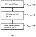
- FIG 2 an embodiment will now be disclosed that relates to a method for enhancing the detection dynamics of a particulate detector. It should be noted that whenever reference is made to the storage of a value in the memory, it is to be understood that the value as such is stored or that a value indicative of this value is stored.
- the first switching-on value I SRC1 relating to the first source of light pulses LED1 can be stored in a storage device (or storage means), for example the memory of the microcontroller.
- the second switching-on value I SRC2 relating to the second source of light pulses LED2 can be stored in the storage device.
- the first reduced switching-on value I SRC1LOW relating to the first source of light pulses LED1 and the second reduced switching-on value I SRC2LOW relating to the second source of light pulses LED2 can be further stored in a storage device.
- a predetermined threshold value indicating whether to operate the particulate detector on the basis of the switching-on values I SRC1 and I SRC2 or whether to operate the particulate detector on the basis of the reduced switching-on values I SRC1LOW and I SRC2LOW will also be stored in the storage device.
- This threshold value could indicate, or correspond to a saturation value (or to a threshold value) of the light radiation detector 11.
- the particulate detector can be operated on the basis of the reduced switching-on values I SRC1LOW and I SRC2LOW when the value detected using the switching-on values I SRC1 and I SRC2 is greater than or equal to the predetermined threshold value. Further, the particulate detector can be operated on the basis of the switching-on values I SRC1 and I SRC2 when the value detected using the reduced switching-on values I SRC1LOW and I SRC2LOW is less or than or equal to a fraction of the predetermined threshold value (for example is less than 10% of the saturation value of the detector).
- the particulate detector is operated on the basis of the switching-on values I SRC1 and I SRC2 or on the basis of the reduced switching-on values I SRC1LOW and I SRC2LOW on the basis of the detected values and on the basis of the predetermined threshold value. Also in other words, the particulate detector is operated on the basis of the switching-on values I SRC1 and I SRC2 or on the basis of the reduced switching-on values I SRC1LOW and I SRC2LOW in function of the threshold value and of the detection values corresponding to the radiation emitted from the first source of light radiation (LED1) and detection values corresponding to the radiation emitted from the second source of light radiation (LED2).
- the threshold value is the same for both the first wavelength ⁇ 1 and for the second wavelength ⁇ 2.
- the switching-on values I SRC1 and I SRC2 can be used to operate the particulate detector on the basis of the detection value detected by the light radiation detector and of the threshold value.
- the reduced switching-on values I SRC1LOW and I SRC2LOW can be used to operate the particulate detector on the basis of the detection value detected by the light radiation detector 11 and of the threshold value.
- the first reduced switching-on value I SRC1LOW and the second reduced switching-on value I SRC2LOW constitute a set of values that are independent of the set of switching-on values I SRC1 and I SRC2 .
- the method for enhancing the detection dynamics will enable the particulate detector, the dynamics of which has been enhanced by the use of two sets of switching-on values, to have extended reading dynamics relating to the first wavelength ⁇ 1 and relating to the second wavelength ⁇ 2 enabling it to evaluate the ratio R between the two signals also in conditions of high concentrations of particulate (e.g. puff of steam, gust of wind, drifting dust or mist) in the presence of which, according to the prior art, it would not have been possible to detect values reliably because of the saturation of the photodiode.
- particulate e.g. puff of steam, gust of wind, drifting dust or mist
- FIG. 3 which shows a specific example of the first embodiment
- a first step T1 it is possible, in a first step T1, to define the first reference switching-on value.
- different switching-on values can be selected and act as a reference switching-on value (i.e. value used to define the corresponding reduced switching-on value).
- the first reference switching-on value coincides with the first switching-on value I SRC1 and the second reference switching-on value coincides with the second switching-on value I SRC2 .
- a first functional relation can be defined between the first switching-on value I SRC1 producing the first detection value S 1 and the first reduced switching-on value I SRC1LOW producing the first reduced detection value S 1LOW .
- a second functional relation can be defined between the second switching-on value I SRC2 producing the second detection value S 2 and the second reduced switching-on value I SRC2LOW producing the second reduced detection value S 2LOW .
- step T3 the first reduced switching-on value I SRC1LOW and the second reduced switching-on value I SRC2LOW are determinable directly from the functional relation and from the respective switching-on values.
- the first functional relation and the second functional relation can take on various shapes until the first reduced detection value S1 LOW constitutes a fraction of the first detection value S1 and the second reduced detection value S2 LOW constitutes a fraction of the second detection value S2.
- the index can be equal to 1 or 2 and indicate respectively the relations between the first switching-on values and the corresponding reduced switching-on values for the first and the second light source and the detection values and reduced detection values for the first and for the second light source.
- f i and f i -1 can indicate the first functional relation or the second functional relation and the respective reverse functions.
- f i can be a generic mathematical function, for example a scale coefficient, or generic polynomial relation.
- the detection dynamics is extended n times.
- the reverse function f i-1 can be a predetermined value, defined during the design stage, so as to define a predetermined ratio of S i to S iLOW and the function fi can be a coefficient determined during the calibration stage.
- the determination during the calibration step can be achieved for example by varying progressively the reduced switching-on value, so that the equation [2] is satisfied.
- a first step U1 it is possible, during a first step U1 to set at least one of the first switching-on value I SRC1 for the first source of light radiation LED1 and the second switching-on value I SRC2 for the second source of light radiation LED2 so that the ratio of the first detection value S1 to the second detection value S2 corresponds to a first predetermined ratio R s .
- the switching-on values are so set that the detector detects the switching-on values according to a predetermined ratio R s .
- the part emitting light (one or both the sources) is set to emit the light at an intensity that is such that the part receiving/revealing the light detects the light according to the desired ratio R s .
- each particulate detector can be subjected to different automated calibration steps and in particular can be subjected to a clean air step, to a smoke tunnel step and to a last clean air step.
- the first wavelength ⁇ 1 could be radiation in a neighbourhood of the infrared whereas the second wavelength ⁇ 2 could be radiation in a neighbourhood of the blue.
- a known response of the particulate detector can be obtained in the presence of known conditions.
- This method comprises a first step S1 of calibration in clean air, wherein a first standard value is set for the particulate detector for the first switching-on value I SRC1 and a second standard value is set for the second switching-on value I SRC2 .
- the response is measured, and a first series of parameters are pre-set.
- the step in clean air S1 is used to determine the component X0 constituting a specific offset of the particulate detector that has to be deducted from the actual reading.
- a second step S2 the detector is made to transit inside a tunnel (smoke tunnel) in which controllable environmental conditions are maintained.
- controllable conditions can include temperature, humidity, particulate concentration and particulate sizes and can be resettable.
- the reference particulate has predetermined features.
- the predetermined ratio R s is predetermined before or during the calibration step or manufacturing step of the particulate detector, for example during a step S3.
- the third step S3 is disclosed in FIG. 5 between the second step S2 and the fourth step S4 only for illustrative purposes and the third step S3 can be carried out at any instant preceding the carrying out of the fourth step S4.
- step S4 it is also possible to set both the first switching-on value I SRC1 for the first source of light pulses LED1 and the second switching-on value I SRC2 for the second source of light pulses LED2 so that the ratio R of the first detection value S1 to the second detection value S2 corresponds to the predetermined ratio R s .
- the meaning of setting a value has to be constructed as including the case in which the given value is set (or fixed) and then varied until the condition of corresponding to another value, for example the reference value, is reached, or setting a value on the basis of predetermined values and choosing the value that is nearest the desired condition.
- an automatic calibration system managing the calibration of the particulate detector can be able to communicate with both the particulate detector that is the object of the calibration and located in the tunnel and with the reference detector.
- At least one of the first switching-on value I SRC1 of the first source of light pulses LED1 and the second switching-on value I SRC2 of the second source of light pulses LED2 can be set so that respectively the first detection value S1 or the second detection value S2 has the same value as that indicated by the reference detector.
- the first detection value S1 and the second detection value can correspond to a multiple or to a fraction of the value indicated by the reference detector.
- the predetermined ratio R s can be a unit ratio, i.e. the second switching-on value I SRC2 of the second source of light pulses LED2 can be so adjusted as to obtain a second detection value S2 that is equal to the first detection value S1.
- the values can be stored in a saving (or storage) step S6. From what has been said, it is clear that the particle detector, when evaluating the ratio between the two signals S1 and S2, to extrapolate the size of the particles, also takes account of the predetermined ratio R s defined previously.
- a particulate detector is further provided that is operable on the basis of light diffusion measurements and that is able to detect particulate on the basis of the ratio R of the first detection value to the second detection value.
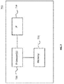
- This particulate detector is disclosed in connection with FIG. 6 and can comprise a first source of light radiation LED1, indicated in the figure by the reference 601, a second source of light radiation LED2, indicated in the figure by the reference 602, a control device (microcontroller) 603, a light radiation detector 604 and a storage device 605.
- a first source of light radiation LED1 indicated in the figure by the reference 601
- a second source of light radiation LED2 indicated in the figure by the reference 602
- a control device (microcontroller) 603 a light radiation detector 604
- the control device can be configured to operate the first source of light radiation 601 and the second source of light radiation 602 respectively in accordance with the first switching-on value I SRC1 and in accordance with the second switching-on value I SRC2 .
- At least one of the first switching-on value I SRC1 and the second switching-on value I SRC2 can be stored in the storage device 605 in a calibration step of the particulate detector.
- information indicative of the at least one of the first switching-on value I SRC1 and the second switching-on value I SRC2 can be stored in the storage device 605 instead of the values themselves.
- the light radiation detector 604 can be configured to detect the first detection value corresponding to the radiation emitted from the first source of light radiation 601 and a second detection value corresponding to the radiation emitted from the second source of light radiation 602.
- first switching-on value I SRC1 and the second switching-on value I SRC2 are such as to produce a predetermined ratio R s of the first detection value to the second detection value.
- control device can be configured to control the first source of light radiation 601 and the second source of light radiation 602 in accordance respectively with the first switching-on value I SRC1 and the second switching-on value I SRC2 , or in accordance respectively with the first reduced switching-on value I SRC1LOW and the second reduced switching-on value I SRC2LOW on the basis of a predetermined threshold value, information indicative of the predetermined threshold value stored in a calibration step of the detector.
- the IF interface is able to receive inputs and/or provide outputs in connection for example with indicative values of the first switching-on value I SRC1 , of the second switching-on value I SRC1 , of the first reduced switching-on value I SRC1LOW and of the second reduced switching-on value I SRC2LOW .
- the interface can receive and/or transmit values associated with the threshold value and/or with the desired reference value S ref .
- the memory 730 can be of any volatile and/or non-volatile type that is able to store at least temporarily one or more of the mentioned values.
- the installer can set in the particulate detector installation step two operating parameters. These operating parameters can be used by the algorithm contained in the internal microcontroller in the evaluation of the signals and in the consequent generation of the alarm signal.
- the enhanced sensitivity coefficient could indicate how reactive the detector has to be to those signals with a BIR ratio > 1 that indicate the presence of particles of smaller sizes so probably combustion fumes.
- the false alarms rejection coefficient could indicate how much the detector has to slow the response to the signals with a BIR ratio ⁇ 1 that indicate the presence of particles of greater sizes that are accordingly probably combustion fume particles.
- the predetermined ratio R s corresponds to the unit ratio. It will nevertheless be apparent to the person skilled in the art that the concepts disclosed below are not limited by the numeric value of the predetermined ratio R s .
- the ratio R between the two measurements provides an indication of the particulate sizes.
- an R > 1 ratio is indicative of a particulate having a diameter ⁇ 0.2 micrometres (probably indicating combustion fumes)
- an R ⁇ 1 ratio is indicative of a particulate having a diameter of > 0.2 micrometres (most likely indicating particulate that does not derive from combustion, and is due to agents like steam, dust, etc).
- particulate detector is not configured to detect smoke but is for example configured to detect particles of another type.
- the calibration operations could be performed at a reference temperature, in accordance with a preferential embodiment, this temperature could be around 25°C.
- the particulate detector and in particular the microcontroller, could be configured to modify the switching-on values I SRC1 , I SRC2 and/or the reduced switching-on values I SRC1LOW and I SRC2LOW of the two light sources LED1 and LED2 in function of the temperature detected according to a predefined functional relation contained in the memory of the microcontroller.
- This predefined functional relation could be appropriately a predefined table stored in the memory of the microcontroller.
- This functional relation could be moreover obtained during the detector development stage and could be determined on the basis of the variations of the features of the components used by the particulate detector in function of the temperature at which they operate and on the basis of the reference temperature at which the calibration of the particulate detector was performed.
- this table could contain temperature values and adjustment values of the switching-on values I SRC1 , I SRC2 and/or of the reduced switching-on values I SRC1LOW and I SRC2LOW .
- the adjustment (or correction) could be a linear adjustment, for example the adjustment value is simply subtracted from or added to the respective initial switching-on value or take on more complex forms, for example polynomial, exponential correction forms etc.
- the functional relation, and accordingly the adjustment values can be the same both for the switching-on values I SRC1 and I SRC2 and for the reduced switching-on values I SRC1LOW and I SRC2LOW .
- the adjustment values can be different for each of the switching-on values I SRC1 and I SRC2 and of the reduced switching-on values I SRC1LOW and I SRC2LOW (for example four different adjustment values for a given temperature).
Landscapes
- Physics & Mathematics (AREA)
- Analytical Chemistry (AREA)
- Chemical & Material Sciences (AREA)
- General Physics & Mathematics (AREA)
- Health & Medical Sciences (AREA)
- Emergency Management (AREA)
- Business, Economics & Management (AREA)
- Life Sciences & Earth Sciences (AREA)
- Biochemistry (AREA)
- General Health & Medical Sciences (AREA)
- Immunology (AREA)
- Pathology (AREA)
- Investigating Or Analysing Materials By Optical Means (AREA)
- Fire-Detection Mechanisms (AREA)
Applications Claiming Priority (2)
| Application Number | Priority Date | Filing Date | Title |
|---|---|---|---|
| IT102018000007932A IT201800007932A1 (it) | 2018-08-07 | 2018-08-07 | Metodo e sistema per la calibrazione di un rilevatore di particolato e rilevatore di particolato |
| IT102018000007931A IT201800007931A1 (it) | 2018-08-07 | 2018-08-07 | Metodo e sistema per aumentare la dinamica di rilevazione di un rilevatore di particolato e rilevatore di particolato |
Publications (2)
| Publication Number | Publication Date |
|---|---|
| EP3608657A2 true EP3608657A2 (fr) | 2020-02-12 |
| EP3608657A3 EP3608657A3 (fr) | 2020-03-25 |
Family
ID=67513474
Family Applications (1)
| Application Number | Title | Priority Date | Filing Date |
|---|---|---|---|
| EP19190485.3A Withdrawn EP3608657A3 (fr) | 2018-08-07 | 2019-08-07 | Procédé et système pour élargir la dynamique de détection d'un détecteur de particules et détecteur de particules. |
Country Status (1)
| Country | Link |
|---|---|
| EP (1) | EP3608657A3 (fr) |
Cited By (1)
| Publication number | Priority date | Publication date | Assignee | Title |
|---|---|---|---|---|
| CN113489901A (zh) * | 2021-06-30 | 2021-10-08 | 维沃移动通信(杭州)有限公司 | 拍摄方法及其装置 |
Family Cites Families (10)
| Publication number | Priority date | Publication date | Assignee | Title |
|---|---|---|---|---|
| JPS62215848A (ja) * | 1986-03-18 | 1987-09-22 | Hochiki Corp | 感知装置 |
| AUPN968896A0 (en) * | 1996-05-06 | 1996-05-30 | Vision Products Pty Ltd | Optical scatter dectector controlling circuit and method |
| GB2397122B (en) * | 2003-01-03 | 2006-02-08 | David Appleby | Fire detector with low false alarm rate |
| US7724367B2 (en) * | 2003-10-23 | 2010-05-25 | Siemens Schweiz Ag | Particle monitors and method(s) therefor |
| CN101512613A (zh) * | 2006-09-07 | 2009-08-19 | 西门子瑞士有限公司 | 涉及微粒监控器及其方法的改进 |
| ATE507544T1 (de) * | 2008-02-19 | 2011-05-15 | Siemens Ag | Rauchdetektion mittels zweier spektral unterschiedlicher streulichtmessungen |
| DE102008010446A1 (de) * | 2008-02-21 | 2009-09-10 | Endress + Hauser Conducta Gesellschaft für Mess- und Regeltechnik mbH + Co. KG | Verfahren und optische Sensoranordnung zum Erfassen einer Messgröße eines Mediums, insbesondere zur Trübungsmessung |
| EP2908298B1 (fr) * | 2014-02-13 | 2018-04-18 | Siemens Schweiz AG | Détecteur de fumée fonctionnant selon le principe de la lumière diffusée comprenant une diode lumineuse bicolore dotée de puces LED de différentes tailles |
| WO2018005213A1 (fr) * | 2016-06-28 | 2018-01-04 | Schlumberger Technology Corporation | Mesure de fraction de phase au moyen d'une source de lumière ajustée |
| EP3287999A1 (fr) * | 2016-08-25 | 2018-02-28 | Siemens Schweiz AG | Procede de detection d'incendie selon le principe de diffusion de la lumiere avec connexion echelonnee d'une autre unite a del pour emettre d'autres impulsions de lumiere de differentes longueurs d'onde et angle de diffusion de lumiere et un tel detecteur de fumee a ecran diffusant |
-
2019
- 2019-08-07 EP EP19190485.3A patent/EP3608657A3/fr not_active Withdrawn
Cited By (2)
| Publication number | Priority date | Publication date | Assignee | Title |
|---|---|---|---|---|
| CN113489901A (zh) * | 2021-06-30 | 2021-10-08 | 维沃移动通信(杭州)有限公司 | 拍摄方法及其装置 |
| CN113489901B (zh) * | 2021-06-30 | 2023-04-28 | 维沃移动通信(杭州)有限公司 | 拍摄方法及其装置 |
Also Published As
| Publication number | Publication date |
|---|---|
| EP3608657A3 (fr) | 2020-03-25 |
Similar Documents
| Publication | Publication Date | Title |
|---|---|---|
| CN114078312B (zh) | 自校准火灾感测设备 | |
| RU2536383C2 (ru) | Оценка сигналов рассеяния света в оптическом устройстве аварийной сигнализации и выдача как взвешенного сигнала плотности дыма, так и взвешенного сигнала плотности пыли/пара | |
| CN102232183B (zh) | 微粒特性的光学探测 | |
| CN113888848B (zh) | 自校准火灾感测设备 | |
| US20070024459A1 (en) | Particle monitors and method(s) therefor | |
| CN108205867A (zh) | 一种具备干扰粒子识别能力的早期火灾烟雾探测方法 | |
| EP3139152A1 (fr) | Détecteur de méthane optique utilisant des harmoniques superieures pour la determination de la concentration de methane | |
| TWI781965B (zh) | 用於估計聚合物材料之參數的可攜式裝置及方法 | |
| US11774282B2 (en) | Pyranometer dome soiling detection with light sensors | |
| KR20140094727A (ko) | 적외선 센서를 이용한 굴뚝 배기 가스의 연기 농도 측정기 | |
| US10753865B2 (en) | Identifying targeted gaseous chemical compound | |
| EP2571001B1 (fr) | Détecteur de flamme utilisant des capteurs optiques. | |
| US12442758B2 (en) | Method for analysing a gas using an optical sensor | |
| TWI861125B (zh) | 微粒感測器 | |
| Deng et al. | Eliminating the effects of refractive indices for both white smokes and black smokes in optical fire detector | |
| EP3472813B1 (fr) | Procédé de détection de fumée | |
| JP2020523572A (ja) | 室内空気の品質の検出および監視を備えたチャンバレス煙検出器 | |
| EP3608657A2 (fr) | Procédé et système pour élargir la dynamique de détection d'un détecteur de particules et détecteur de particules. | |
| US11650152B2 (en) | Calibration of an optical detector | |
| US11662302B2 (en) | Calibration of optical detector | |
| US9881491B2 (en) | Fire detector comprising a MOS gas sensor and a photoelectric detector | |
| JP2008232918A (ja) | ガス検知装置 | |
| CN119251969A (zh) | 监视自测试火灾感测设备 | |
| IT201800007931A1 (it) | Metodo e sistema per aumentare la dinamica di rilevazione di un rilevatore di particolato e rilevatore di particolato | |
| US12567321B2 (en) | Testing a heat detector of a self-testing hazard sensing device |
Legal Events
| Date | Code | Title | Description |
|---|---|---|---|
| PUAI | Public reference made under article 153(3) epc to a published international application that has entered the european phase |
Free format text: ORIGINAL CODE: 0009012 |
|
| STAA | Information on the status of an ep patent application or granted ep patent |
Free format text: STATUS: THE APPLICATION HAS BEEN PUBLISHED |
|
| AK | Designated contracting states |
Kind code of ref document: A2 Designated state(s): AL AT BE BG CH CY CZ DE DK EE ES FI FR GB GR HR HU IE IS IT LI LT LU LV MC MK MT NL NO PL PT RO RS SE SI SK SM TR |
|
| AX | Request for extension of the european patent |
Extension state: BA ME |
|
| PUAL | Search report despatched |
Free format text: ORIGINAL CODE: 0009013 |
|
| AK | Designated contracting states |
Kind code of ref document: A3 Designated state(s): AL AT BE BG CH CY CZ DE DK EE ES FI FR GB GR HR HU IE IS IT LI LT LU LV MC MK MT NL NO PL PT RO RS SE SI SK SM TR |
|
| AX | Request for extension of the european patent |
Extension state: BA ME |
|
| RIC1 | Information provided on ipc code assigned before grant |
Ipc: G08B 17/10 20060101ALI20200219BHEP Ipc: G01N 21/53 20060101AFI20200219BHEP |
|
| STAA | Information on the status of an ep patent application or granted ep patent |
Free format text: STATUS: REQUEST FOR EXAMINATION WAS MADE |
|
| 17P | Request for examination filed |
Effective date: 20200924 |
|
| RBV | Designated contracting states (corrected) |
Designated state(s): AL AT BE BG CH CY CZ DE DK EE ES FI FR GB GR HR HU IE IS IT LI LT LU LV MC MK MT NL NO PL PT RO RS SE SI SK SM TR |
|
| STAA | Information on the status of an ep patent application or granted ep patent |
Free format text: STATUS: THE APPLICATION IS DEEMED TO BE WITHDRAWN |
|
| 18D | Application deemed to be withdrawn |
Effective date: 20230301 |