EP3608877A1 - Structure de reconstruction d'images itératives - Google Patents
Structure de reconstruction d'images itératives Download PDFInfo
- Publication number
- EP3608877A1 EP3608877A1 EP19188957.5A EP19188957A EP3608877A1 EP 3608877 A1 EP3608877 A1 EP 3608877A1 EP 19188957 A EP19188957 A EP 19188957A EP 3608877 A1 EP3608877 A1 EP 3608877A1
- Authority
- EP
- European Patent Office
- Prior art keywords
- image
- datafit
- sinogram
- iterative
- denoising
- Prior art date
- Legal status (The legal status is an assumption and is not a legal conclusion. Google has not performed a legal analysis and makes no representation as to the accuracy of the status listed.)
- Granted
Links
Images



Classifications
-
- G—PHYSICS
- G06—COMPUTING OR CALCULATING; COUNTING
- G06T—IMAGE DATA PROCESSING OR GENERATION, IN GENERAL
- G06T5/00—Image enhancement or restoration
- G06T5/70—Denoising; Smoothing
-
- G—PHYSICS
- G06—COMPUTING OR CALCULATING; COUNTING
- G06T—IMAGE DATA PROCESSING OR GENERATION, IN GENERAL
- G06T12/00—Tomographic reconstruction from projections
- G06T12/20—Inverse problem, i.e. transformations from projection space into object space
-
- G—PHYSICS
- G06—COMPUTING OR CALCULATING; COUNTING
- G06N—COMPUTING ARRANGEMENTS BASED ON SPECIFIC COMPUTATIONAL MODELS
- G06N3/00—Computing arrangements based on biological models
- G06N3/02—Neural networks
- G06N3/04—Architecture, e.g. interconnection topology
- G06N3/045—Combinations of networks
-
- G—PHYSICS
- G06—COMPUTING OR CALCULATING; COUNTING
- G06N—COMPUTING ARRANGEMENTS BASED ON SPECIFIC COMPUTATIONAL MODELS
- G06N3/00—Computing arrangements based on biological models
- G06N3/02—Neural networks
- G06N3/04—Architecture, e.g. interconnection topology
- G06N3/045—Combinations of networks
- G06N3/0455—Auto-encoder networks; Encoder-decoder networks
-
- G—PHYSICS
- G06—COMPUTING OR CALCULATING; COUNTING
- G06N—COMPUTING ARRANGEMENTS BASED ON SPECIFIC COMPUTATIONAL MODELS
- G06N3/00—Computing arrangements based on biological models
- G06N3/02—Neural networks
- G06N3/04—Architecture, e.g. interconnection topology
- G06N3/0464—Convolutional networks [CNN, ConvNet]
-
- G—PHYSICS
- G06—COMPUTING OR CALCULATING; COUNTING
- G06N—COMPUTING ARRANGEMENTS BASED ON SPECIFIC COMPUTATIONAL MODELS
- G06N3/00—Computing arrangements based on biological models
- G06N3/02—Neural networks
- G06N3/08—Learning methods
- G06N3/084—Backpropagation, e.g. using gradient descent
-
- G—PHYSICS
- G06—COMPUTING OR CALCULATING; COUNTING
- G06N—COMPUTING ARRANGEMENTS BASED ON SPECIFIC COMPUTATIONAL MODELS
- G06N3/00—Computing arrangements based on biological models
- G06N3/02—Neural networks
- G06N3/08—Learning methods
- G06N3/09—Supervised learning
-
- G—PHYSICS
- G06—COMPUTING OR CALCULATING; COUNTING
- G06T—IMAGE DATA PROCESSING OR GENERATION, IN GENERAL
- G06T3/00—Geometric image transformations in the plane of the image
-
- G—PHYSICS
- G06—COMPUTING OR CALCULATING; COUNTING
- G06T—IMAGE DATA PROCESSING OR GENERATION, IN GENERAL
- G06T2207/00—Indexing scheme for image analysis or image enhancement
- G06T2207/10—Image acquisition modality
- G06T2207/10072—Tomographic images
- G06T2207/10081—Computed x-ray tomography [CT]
-
- G—PHYSICS
- G06—COMPUTING OR CALCULATING; COUNTING
- G06T—IMAGE DATA PROCESSING OR GENERATION, IN GENERAL
- G06T2211/00—Image generation
- G06T2211/40—Computed tomography
- G06T2211/421—Filtered back projection [FBP]
-
- G—PHYSICS
- G06—COMPUTING OR CALCULATING; COUNTING
- G06T—IMAGE DATA PROCESSING OR GENERATION, IN GENERAL
- G06T2211/00—Image generation
- G06T2211/40—Computed tomography
- G06T2211/424—Iterative
-
- G—PHYSICS
- G06—COMPUTING OR CALCULATING; COUNTING
- G06T—IMAGE DATA PROCESSING OR GENERATION, IN GENERAL
- G06T2211/00—Image generation
- G06T2211/40—Computed tomography
- G06T2211/441—AI-based methods, deep learning or artificial neural networks
-
- G—PHYSICS
- G06—COMPUTING OR CALCULATING; COUNTING
- G06T—IMAGE DATA PROCESSING OR GENERATION, IN GENERAL
- G06T2211/00—Image generation
- G06T2211/40—Computed tomography
- G06T2211/444—Low dose acquisition or reduction of radiation dose
Definitions
- the subject matter disclosed herein relates to iterative reconstruction of images using non-invasively acquired scan data.
- Non-invasive imaging technologies allow images of the internal structures or features of a patient/object to be obtained without performing an invasive procedure on the patient/object.
- such non-invasive imaging technologies rely on various physical principles (such as the differential transmission of X-rays through a target volume, the reflection of acoustic waves within the volume, the paramagnetic properties of different tissues and materials within the volume, the breakdown of targeted radionuclides within the body, and so forth) to acquire data and to construct images or otherwise represent the observed internal features of the patient/object.
- Reconstruction of images using non-invasively acquired scan data may be performed using various types of reconstruction processes and algorithms. All reconstruction processes and algorithms are subject to various trade-offs, such as between computational efficiency, patient dose, scanning speed, image quality, and artifacts.
- computed tomography (CT) images may be subject to image noise due to the quantum nature of X-rays and detector readout noise.
- image noise increases when radiation dose is increased or when the spatial resolution is increased.
- the reconstruction process preserves low-contrast details and that the reconstruction process is computationally efficient.
- a method for reconstructing an image.
- a sinogram input is received.
- One or more intermediate sinograms is generated from the sinogram input or from one or more intermediate images generated from the sinogram input.
- the one or more intermediate sinograms is iteratively processed.
- the iterative processing comprises performing at least an iterative datafit operation comparing an output of an iterative loop with an input to the iterative loop.
- a denoising operation is performed in addition to the datafit operation.
- the denoising operation is performed using a trained artificial neural network.
- a method for reconstructing an image.
- a sinogram input is received.
- An initial reconstruction or multiple partial reconstructions of the sinogram input is performed to generate an intermediate image or multiple intermediate images.
- the one or more intermediate images or a transform of the one or more intermediate images is iteratively processed.
- the iterative processing comprises performing at least an iterative datafit operation comparing an output of an iterative loop with an input to the iterative loop.
- a denoising operation is performed in addition to the datafit operation.
- the denoising operation is performed using a trained artificial neural network.
- a method for reconstructing an image.
- a sinogram input is received.
- a first denoising operation is performed on the sinogram input using a first trained artificial neural network.
- the sinogram input is reconstructed to generate one or more reconstructed images.
- a second denoising operation is performed in the image domain using a second trained artificial neural network.
- a final image is output for review, storage, or further processing.
- CT Computed Tomography
- the present disclosure may be useful in any imaging or screening context or image processing field where a set or type of acquired data undergoes a reconstruction process to generate an image or volume.
- spectral CT produces a set of images, including monochromatic images at different energies as well as basis material decomposition images.
- dynamic CT or PET produces a set of images at different time points.
- the current invention may be applied to these sets or types of images as well as others.
- CT and C-arm examples are primarily provided herein, it should be understood that the disclosed technique may be used in other imaging modality contexts where iterative tomographic reconstruction processes are employed.
- the presently described approach may also be employed on data acquired by other types of tomographic scanners including, but not limited to, positron emission tomography (PET) scanners, single photon emission computed tomography (SPECT) scanners, and/or magnetic resonance imaging (MRI) scanners.
- PET positron emission tomography
- SPECT single photon emission computed tomography
- MRI magnetic resonance imaging
- imaging modalities such as X-ray CT (e.g., multislice CT) and X-ray C-arm systems (e.g., cone-beam CT), measure projections of the object or patient being scanned where the projections, depending on the technique, correspond to Radon transform data, fan-beam transform data, cone-beam transform data, or non-uniform Fourier transforms.
- the scan data may be emission type data (e.g., PET or SPECT data) or magnetic resonance data (e.g., MRI data) generated in response to magnetic fields and RF pulses. Iterative tomographic reconstruction algorithms and related correction and calibration algorithms are employed in conjunction with these imaging modalities to generate useful cross-sectional images or volumetric images from raw measurements.
- the present disclosure relates to image reconstruction with favorable properties in terms of noise reduction, spatial resolution, detail preservation and computational complexity.
- the disclosed technique may include some or all of three different aspects: a first-pass reconstruction, a simplified datafit term, and a deep learning denoiser.
- the term "datafit” may be understood to mean the reconstruction cost function term that defines the level of consistency of an estimated solution or set of variables (e.g., a reconstructed image) with the measured data (e.g., a sinogram).
- a datafit term may be the weighted least squares error between the measured sinogram and the reprojection of an estimated reconstructed image.
- the "datafit operation” may also define the level of consistency of the estimated solution or set of variables (e.g., a reconstructed image) with a transform of the measured data as discussed herein (e.g., reprojection of an initial reconstruction from the measured data).
- a “datafit operation” or “datafit update”, as used herein may be understood to refer to an iterative update of an estimated solution, where the iterative update is designed to enhance consistency of the estimated solution with the measured data or indirectly with a transform of the measured data.
- the simplicity of a direct reconstruction approach may be obtained along with the noise reduction capability of deep learning, with the statistical benefit of a data-fit term.
- the present disclosure is easily portable to different CT platforms, such as by incorporating a first-pass reconstruction step, as discussed herein.
- deep-learning approaches may be employed with respect to denoising of an image.
- the deep learning denoising steps discussed herein may include approaches based on a residual network, a generative adversarial network, or another loss network.
- such deep-learning approaches may utilize neural networks in this denoising role as part of the reconstruction process used to generate tomographic images, such as CT, PET, SPECT, C-arm, phase-contrast, and MR images.
- Neural networks as discussed herein may encompass deep neural networks, fully connected networks, convolutional neural networks (CNNs), perceptrons, auto encoders, recurrent networks, wavelet filter banks based neural networks, or other neural network architectures. These techniques are referred to herein as deep learning techniques, though this terminology may also be used specifically in reference to the use of deep neural networks, which is a neural network having a plurality of layers.
- deep learning techniques are a branch of machine learning techniques that employ mathematical representations of data and artificial neural network for learning.
- deep learning approaches may be characterized by their use of one or more algorithms to extract or model high level abstractions of a type of data of interest. This may be accomplished using one or more processing layers, with each layer typically corresponding to a different level of abstraction and, therefore potentially employing or utilizing different aspects of the initial data or outputs of a preceding layer (i.e., a hierarchy or cascade of layers) as the target of the processes or algorithms of a given layer. In an image processing or reconstruction context, this may be characterized as different layers corresponding to the different feature levels or resolution in the data.
- the processing from one representation space to the next-level representation space can be considered as one 'stage' of the reconstruction process.
- Each stage of the reconstruction can be performed by separate neural networks or by different parts of one larger neural network.
- a single deep learning network may be used to provide denoising of an image as a step in a reconstruction process.
- training data sets may be employed that have known initial values (e.g., input images, projection data, emission data, magnetic resonance data, and so forth) and known or desired values for a final output (e.g., reconstructed tomographic reconstructions, such as de-noised cross-sectional images or volumetric representations) of the deep learning process.
- the training of a single stage may have known input values corresponding to one representation space and known output values corresponding to a next-level representation space.
- the deep learning algorithms may process (either in a supervised or guided manner or in an unsupervised or unguided manner) the known or training data sets until the mathematical relationships between the initial data and desired output(s) are discerned and/or the mathematical relationships between the inputs and outputs of each layer are discerned and characterized.
- separate validation data sets may be employed in which both the initial and desired target values are known, but only the initial values are supplied to the trained deep learning algorithms, with the outputs then being compared to the outputs of the deep learning algorithm to validate the prior training and/or to prevent over-training.
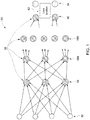
- FIG. 1 schematically depicts an example of an artificial neural network 50 that may be trained as a deep learning model as discussed herein.
- the network 50 is multi-layered, with a training input 52 and multiple layers including an input layer 54, hidden layers 58A, 58B, and so forth, and an output layer 60 and the training target 64 present in the network 50.
- Each layer in this example, is composed of a plurality of "neurons" or nodes 56.
- the number of neurons 56 may be constant between layers or, as depicted, may vary from layer to layer.
- Neurons 56 at each layer generate respective outputs that serve as inputs to the neurons 56 of the next hierarchical layer.
- a weighted sum of the inputs with an added bias is computed to "excite” or “activate” each respective neuron of the layers according to an activation function, such as rectified linear unit (ReLU), sigmoid function, hyperbolic tangent function, or otherwise specified or programmed.
- the outputs of the final layer constitute the network output 60 (e.g., predicted image) which, in conjunction with a target image 64, are used to compute some loss or error function 62, which will be backpropagated to guide the network training.
- the loss or error function 62 measures the difference between the network output (i.e., a denoised image) and the training target.
- the loss function may be the mean squared error (MSE) of the voxel-level values or partial-line-integral values and/or may account for differences involving other image features, such as image gradients or other image statistics.
- MSE mean squared error
- the loss function 62 could be defined by other metrics associated with the particular task in question, such as a softmax function.
- the present disclosure primarily discusses these approaches in the context of a CT or C-arm system. However, it should be understood that the following discussion may also be applicable to other image modalities and systems including, but not limited to, PET, SPECT, multi-spectral CT, phase-contrast imaging, and MRI, as well as to non-medical contexts or any context where tomographic reconstruction is employed to reconstruct an image.
- an imaging system 110 i.e., a scanner
- the imaging system 110 is a CT imaging system designed to acquire scan data (e.g., X-ray attenuation data) at a variety of views around a patient (or other subject or object of interest) and suitable for performing image reconstruction using tomographic reconstruction techniques.
- scan data e.g., X-ray attenuation data
- imaging system 110 includes a source of X-ray radiation 112 positioned adjacent to a collimator 114.
- the X-ray source 112 may be an X-ray tube, a distributed X-ray source (such as a solid-state or thermionic X-ray source) or any other source of X-ray radiation suitable for the acquisition of medical or other images.
- a toroidal radiation detector may be provided and a radio-active tracer is used as a radiation source.
- the measurements are samples in Fourier space and can either be applied directly as the input to the neural network or can first be converted to line integrals in sinogram space.
- the collimator 114 shapes or limits a beam of X-rays 116 that passes into a region in which a patient/object 118, is positioned.
- the X-rays 116 are collimated to be a cone-shaped beam, i.e., a cone-beam, that passes through the imaged volume.
- a portion of the X-ray radiation 120 passes through or around the patient/object 118 (or other subject of interest) and impacts a detector array, represented generally at reference numeral 122. Detector elements of the array produce electrical signals that represent the intensity of the incident X-rays 120. These signals are acquired and processed to reconstruct images of the features within the patient/object 118.
- Source 112 is controlled by a system controller 124, which furnishes both power, and control signals for CT examination sequences, including acquisition of two-dimensional localizer or scout images used to identify anatomy of interest within the patient/object for subsequent scan protocols.
- the system controller 124 controls the source 112 via an X-ray controller 126 which may be a component of the system controller 124.
- the X-ray controller 126 may be configured to provide power and timing signals to the X-ray source 112.
- the detector 122 is coupled to the system controller 124, which controls acquisition of the signals generated in the detector 122.
- the system controller 124 acquires the signals generated by the detector using a data acquisition system 128.
- the data acquisition system 128 receives data collected by readout electronics of the detector 122.
- the data acquisition system 128 may receive sampled analog signals from the detector 122 and convert the data to digital signals for subsequent processing by a processor 130 discussed below.
- the digital-to-analog conversion may be performed by circuitry provided on the detector 122 itself.
- the system controller 124 may also execute various signal processing and filtration functions with regard to the acquired image signals, such as for initial adjustment of dynamic ranges, interleaving of digital image data, and so forth.
- system controller 124 is coupled to a rotational subsystem 132 and a linear positioning subsystem 134.
- the rotational subsystem 132 enables the X-ray source 112, collimator 114 and the detector 122 to be rotated one or multiple turns around the patient/object 118, such as rotated primarily in an x,y-plane about the patient.
- the rotational subsystem 132 might include a gantry or C-arm upon which the respective X-ray emission and detection components are disposed.
- the system controller 124 may be utilized to operate the gantry or C-arm.
- the linear positioning subsystem 134 may enable the patient/object 118, or more specifically a table supporting the patient, to be displaced within the bore of the CT system 110, such as in the z-direction relative to rotation of the gantry.
- the table may be linearly moved (in a continuous or step-wise fashion) within the gantry to generate images of particular areas of the patient 118.
- the system controller 124 controls the movement of the rotational subsystem 132 and/or the linear positioning subsystem 134 via a motor controller 136.
- system controller 124 commands operation of the imaging system 110 (such as via the operation of the source 112, detector 122, and positioning systems described above) to execute examination protocols and to process acquired data.
- the system controller 124 via the systems and controllers noted above, may rotate a gantry supporting the source 112 and detector 122 about a subject of interest so that X-ray attenuation data may be obtained at one or more views relative to the subject.
- system controller 124 may also include signal processing circuitry, associated memory circuitry for storing programs and routines executed by the computer (such as routines for performing tomographic reconstruction techniques described herein), as well as configuration parameters, image data, and so forth.
- the image signals acquired and processed by the system controller 124 are provided to a processing component 130 for reconstruction of images in accordance with the presently disclosed algorithms.
- the processing component 130 may be one or more general or application-specific microprocessors.
- the data collected by the data acquisition system 128 may be transmitted to the processing component 130 directly or after storage in a memory 138.
- Any type of memory suitable for storing data might be utilized by such an exemplary system 110.
- the memory 138 may include one or more optical, magnetic, and/or solid state memory storage structures.
- the memory 138 may be located at the acquisition system site and/or may include remote storage devices for storing data, processing parameters, and/or routines for tomographic image reconstruction, as described below.
- the processing component 130 may be configured to receive commands and scanning parameters from an operator via an operator workstation 140, typically equipped with a keyboard and/or other input devices.
- An operator may control the system 110 via the operator workstation 140.
- the operator may observe the reconstructed images and/or otherwise operate the system 110 using the operator workstation 140.
- a display 142 coupled to the operator workstation 140 may be utilized to observe the reconstructed images and to control imaging.
- the images may also be printed by a printer 144 which may be coupled to the operator workstation 140.
- processing component 130 and operator workstation 140 may be coupled to other output devices, which may include standard or special purpose computer monitors and associated processing circuitry.
- One or more operator workstations 140 may be further linked in the system for outputting system parameters, requesting examinations, viewing images, and so forth.
- displays, printers, workstations, and similar devices supplied within the system may be local to the data acquisition components, or may be remote from these components, such as elsewhere within an institution or hospital, or in an entirely different location, linked to the image acquisition system via one or more configurable networks, such as the Internet, virtual private networks, and so forth.
- the operator workstation 140 may also be coupled to a picture archiving and communications system (PACS) 146.
- PACS 146 may in turn be coupled to a remote client 148, radiology department information system (RIS), hospital information system (HIS) or to an internal or external network, so that others at different locations may gain access to the raw or processed image data.
- RIS radiology department information system
- HIS hospital information system
- the processing component 130, memory 138, and operator workstation 140 may be provided collectively as a general or special purpose computer or workstation configured to operate in accordance with the aspects of the present disclosure.
- the general or special purpose computer may be provided as a separate component with respect to the data acquisition components of the system 110 or may be provided in a common platform with such components.
- the system controller 124 may be provided as part of such a computer or workstation or as part of a separate system dedicated to image acquisition.
- the system of FIG. 2 may be utilized to acquire X-ray projection data (or other scan data for other modalities) for a variety of views about a region of interest of a patient to reconstruct images of the imaged region using the scan data.
- Projection (or other) data acquired by a system such as the imaging system 110 may be reconstructed as discussed herein to perform a tomographic reconstruction.
- the disclosed technique may include some or all of three different aspects: a first-pass reconstruction, a simplified datafit term, and an image-domain deep learning denoiser.
- a first-pass reconstruction may be obtained along with the noise reduction capability of deep learning, with the statistical benefit of a data-fit term.
- the disclosed technique is easily portable to different CT platforms, such as by incorporating a first-pass reconstruction step, as discussed herein.
- a measured sinogram 190 may first undergo various, optional pre-processing steps 192.
- sinogram processing may include removing or otherwise correcting for low signal artifacts present in the sinogram 190 that might result in artifacts that are more difficult to address in the image domain.
- beam hardening correction or scatter correction may also be performed as part of the pre-processing step(s) 192.
- a first-pass reconstruction 194 converts the sinogram 190 to an intermediate image 198 (or image volume), which is then used as the input to an iterative processing step, such as an iterative process including one or both of a datafit operation 202 and a deep learning denoising operation 204, to produce a final image 208.
- an iterative processing step such as an iterative process including one or both of a datafit operation 202 and a deep learning denoising operation 204, to produce a final image 208.
- the datafit and denoising operations are performed in parallel, but they may alternatively be performed in series.
- the datafit operation 202 or comparison is similar to the datafit operation performed in model-based iterative reconstruction (MBIR). However, unlike MBIR operations, the present datafit operations 202 and/or updates correspond to a comparison and update step performed on the output of the most recent iteration and an intermediate reconstruction or sinogram (e.g., intermediate image 198), as opposed to the original measured data.
- the datafit operation 202 helps retain spatial resolution by referring back to the image or data at an earlier state, here the initial intermediate image 198.
- the datafit operation 202 also allows statistical modeling to be applied and thereby improves both spatial resolution and statistical efficiency of the process.
- the first pass reconstruction 194 is an analytic reconstruction, such as a filtered backprojection (FBP) or, in one implementation, an information-preserving filtered-backprojection reconstruction (IPFBP).
- FBP filtered backprojection
- IPFBP information-preserving filtered-backprojection reconstruction
- Filtered backprojection typically suppresses image noise for optimized image quality or task performance with human observers, although at the cost of losing spatial resolution or information relative the measured sinogram 190.
- IPFBP reconstructions are a type of FBP reconstruction designed or configured to avoid or reduce resolution loss, i.e., to preserve information present in the measured sinogram 190.
- IPFBP may be have smaller voxel size (e.g., using a 1024x1024 or 2048x2048 image matrix as opposed to a 512x512 image matrix), a higher-pass kernel (e.g., amplifying certain or select frequencies in comparison to a standard ramp filter), and/or higher up-sampling ratio for filtering or backprojection of the sinogram (e.g., up-sampling the sinogram by a factor of 2 to 4 during filtering and backprojection).
- the reconstruction kernel may be empirically defined to minimize the error between the reprojection of the FBP-reconstruction and the measured sinogram 190.
- Such an IPFBP reconstruction may be optimized for non-human analysis or processing (e.g., by a trained neural network) in a subsequent step, as opposed to direct review by a human reviewer.
- a visual comparison is provided between images reconstructed by a standard FBP (left side) versus an IPFBP algorithm, which can be used as the first-pass reconstruction 194 as discussed herein.
- the standard FBP reconstruction was performed using a 512 x 512 reconstruction grid, a standard filter kernel, and no upsampling of the detector data before backprojection.
- the IPFBP reconstruction used a 1024 x 1024 reconstruction grid, a high-resolution filter kernel (i.e., a higher-resolution filter kernel designed by minimizing the error between the reprojection of the FBP-reconstruction and the measured sinogram), and 4X upsampling of the detector data before backprojection.
- the depicted standard FBP image 220 has lower noise level and smoother appearance
- the depicted IPFBP image 222 contains more information, as evidenced by the fine resolution features visible only in the IPFBP image.
- the respective residual error sinograms 224, 226 for each reconstruction are also depicted for comparison, which further illustrates the relative reduction in residual error obtained in the IPFBP reconstruction.
- the sinogram processing step 192 may be or may include a sinogram denoising step 230 (e.g., a deep learning sinogram denoising step performed using a trained neural network or convolutional neural network) distinct from the denoising step 204 performed in the image domain.
- a sinogram denoising step 230 performed in the projection domain could be applied primarily on a lowest-signal portion of the sinogram 190. This preferential application to such a low-signal portion of the sinogram 190 can be achieved either explicitly by a weighting function or implicitly by a deep learning denoising network.
- the datafit operation 202 may take the form of a datafit update 232 performed using a reprojection (reprojection step 234) of the first-pass reconstruction (i.e., the datafit term is based on an intermediate image 198 generated by filtered backprojection 238) to generate an intermediate sinogram 236.
- This intermediate sinogram 236 may then be employed as an input to an iterative reconstruction update step (i.e., the datafit update 232 with deep learning based denoising, which may serve as a regularization term to the iterative process), such as with corresponding statistical weights for optimal noise behavior.
- the reprojection operation 234 can be performed on different portions of the intermediate image 198 (i.e., limited portions of the intermediate image 198) at different steps or times for improved computational efficiency, e.g., by splitting the reprojection task into smaller pieces.
- the reprojection step 234 and may be simplified to a two-dimensional parallel-beam or fan-beam or fan-parallel-beam reprojection and a reduced number of views relative to the acquisition geometry and/or number of views used to acquire the original sinogram 190.
- the reprojection step 234 can also be performed with virtual source orbits and/or detector positions different than those actually employed to acquire the initial scan data (including virtual source orbits and/or detector positions that are not practical or possible with the physical source and detector installed on the scanner). In this manner, various benefits, including computational efficiency and image quality improvement, may be obtained.
- the rotation axis of the source orbit can be offset or oblique relative to the physical rotation axis.
- the filtered backprojection 238 and intermediate image 198 can also be a simplified partial reconstruction, such as over a partial angular range (as opposed to a diagnostic quality or conventional resolution reconstruction), that is sufficient for the purpose of the subsequent reprojection step 234.
- the intermediate image 198 can be a set of limited angle reconstructions that have larger pixel size along the corresponding direction of reprojection rays.
- the computation cost of both the first-pass reconstruction (e.g., FBP 238) and the reprojection step 234 can be reduced.
- multiple intermediate images or intermediate sinograms that correspond to different projection angles can be generated.
- FIGS. 5-7 differ in the manner in which the datafit operation (e.g., datafit update 232) and denoising operation (e.g., deep learning denoising 204) are coordinated. As may be appreciated, these operations may be performed and combined in various permutations, three examples of which are depicted in FIGS. 5-7 . It should be understood, however, that other process flows and combinations of steps are contemplated and encompassed by the present discussion.
- datafit operation e.g., datafit update 232
- denoising operation e.g., deep learning denoising 204
- the deep learning denoising operation 204 is combined (step 240) with the datafit update 232 in a parallel manner within an iterative loop such that each iteration of the loop generates a reconstructed image 242 that is input to the respective datafit update 232 and denoising operation 204 for the next iteration until a set number of iterations are performed or some other completion threshold (e.g., a cost function) is met, at which time the most recent reconstructed image 242 is the final image 208.
- a set number of iterations e.g., a cost function
- the deep learning denoising operation 204 is combined (step 240) with the datafit update 232 in a sequential manner within the iterative loop such that the corresponding reconstructed image 242 generated by a respective iteration is input to the respective datafit update 232 for the next iteration until a set number of iterations are performed or some other completion threshold (e.g., a cost function) is met, at which time the most recent reconstructed image 242 is the final image 208.
- a set number of iterations e.g., a cost function
- the deep learning denoising operation 204 is performed outside of the iterative loop on the final reconstructed image 242 to generate the final image 208.
- the corresponding reconstructed image 242 generated by a respective iteration is input to the respective datafit operation 232 for the next iteration until a set number of iterations are performed or some other completion threshold (e.g., a cost function) is met.
- the resulting reconstructed image 242 is output from the iterative update process and subjected to denoising 204 to generate the final image 208.
- the datafit term (e.g., datafit update 232) may be based on image transforms of the intermediate image 198.
- the datafit update 232 of an iterative process may be based on a (local) Fourier transform 250 (yielding Fourier data 252) of a first-pass reconstruction (e.g., FBP 238).
- the datafit term can include Fourier-based weighting.
- the Fourier transform e.g., a fast Fourier transform (FFT)
- FFT fast Fourier transform
- other image transforms such as wavelet frames, may also be used as the datafit term.
- the process flow example illustrated in FIG. 8 corresponds to the sequential flow illustrated in FIG. 6 .
- the deep learning denoising step 204 in this example can be applied in different configurations, including the parallel and outside-the-iterative-loop example process flows illustrated in FIGS. 5 and 7 , as well as other suitable process flow configurations.
- the datafit term is based directly on the first-pass reconstruction (e.g., an intermediate image 198 generated from a filtered backprojection 238).
- the datafit term is in the image domain (i.e., an image domain datafit update 260).
- the datafit term can include a spatial correlation term to account for correlated noise.
- the reconstructed image 242 of a given iteration loop is used as an input to the image-domain datafit update step 260 until the iterations are completed.
- the datafit term can also include multiple intermediate images, e.g., images that correspond to different projection angles.
- the process flow example illustrated in FIG. 9 corresponds to the sequential flow illustrated in FIG. 6 .
- the deep learning denoising step 204 in this example can be applied in different configurations, including the parallel and outside-the-iterative-loop example process flows illustrated in FIGS. 5 and 7 , as well as other suitable process flow configurations.
- FIG. 10 depicts a process flow that includes sinogram deep learning denoising 230 of a sinogram 190 followed by a reconstruction step 194, such as FBP or IPFBP.
- the result of the reconstruction step 194 i.e., an image
- An optional datafit operation 202 can also be applied in conjunction with the deep learning denoising 204, after the first-pass reconstruction 194, as part of the depicted process flow.
- an intermediate sinogram 236 is generated directly from the pre-processed sinogram 190 by sinogram rebinning 270.
- the intermediate sinogram 236 can be generated by rebinning in various ways, such as by application of simplified, modified, or virtual projection geometries.
- new sinogram data for use in the intermediate sinogram 236 can be generated according to a consistency condition and/or through application of deep learning approaches (e.g., a trained neural network). Such approaches can be done for various computational or image quality benefits.
- the datafit and image-domain denoising operations can be applied in sequence, in parallel, with the denoising occurring outside-the-iterative-loop.
- a deep learning network e.g., a trained neural network
- Such a parallel processing approach i.e., running different processes in parallel that generate a different but comparable output
- subsequent generation or selection of a single, final image may be referred to as "bagging" and may be useful for combining the advantages and avoiding or reducing the disadvantages of the respective individual techniques.
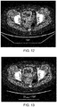
- FIGS. 12-15 depict reconstructed images (here clinical CT scans of a pelvis) corresponding to different operations discussed and described herein to facilitate comparison of the effects of the operations alone and in combination.
- FIG. 12 corresponds to a reconstructed image generated using a standard filtered backprojection (FBP) algorithm, which may thus correspond to a first-pass reconstruction as used herein.
- FBP filtered backprojection
- FIG. 13 illustrates a filtered backprojection reconstruction of the same measured sinogram data as FIG. 12 .
- a sinogram-domain (i.e., projection space) deep learning denoising operation was performed prior to the FBP operation.
- the sinogram-domain (i.e., projection space) deep learning denoising operation was implemented as an 8-layer fully-connected network with interlayer connections.
- FIG. 14 builds upon this sequence of operations exemplified in FIG. 13 by adding an image-domain (i.e., image space) deep learning denoising operation performed subsequent to the FBP operation.
- image-domain deep learning denoising operation was implemented as an 8-layer contracting path-based convolutional encoder-decoder.
- FIG. 15 depicts an image reconstruction with two additional variations.
- the first pass reconstruction is instead performed using an information-preserving filtered-backprojection (IPFBP) algorithm, as discussed herein.
- IPFBP information-preserving filtered-backprojection
- a datafit term (implemented using a datafit update as discussed herein) was employed this example, for image-domain denoising.
- the combined DL sino + IPFBP + datafit + DL img algorithm used to generate FIG. 15 was implemented in accordance with the process flow illustrated in FIG 7 .
- the disclosed techniques may include some or all of: a first-pass reconstruction, a simplified datafit term, and/or a deep learning denoiser.
- the present disclosure is portable to different CT platforms, such as by incorporating a first-pass reconstruction step.
Landscapes
- Engineering & Computer Science (AREA)
- Physics & Mathematics (AREA)
- Theoretical Computer Science (AREA)
- General Physics & Mathematics (AREA)
- Mathematical Physics (AREA)
- General Health & Medical Sciences (AREA)
- Computing Systems (AREA)
- Biomedical Technology (AREA)
- Biophysics (AREA)
- Computational Linguistics (AREA)
- Data Mining & Analysis (AREA)
- Evolutionary Computation (AREA)
- Life Sciences & Earth Sciences (AREA)
- Molecular Biology (AREA)
- Artificial Intelligence (AREA)
- General Engineering & Computer Science (AREA)
- Health & Medical Sciences (AREA)
- Software Systems (AREA)
- Apparatus For Radiation Diagnosis (AREA)
- Magnetic Resonance Imaging Apparatus (AREA)
- Nuclear Medicine (AREA)
- Algebra (AREA)
- Mathematical Analysis (AREA)
- Mathematical Optimization (AREA)
- Pure & Applied Mathematics (AREA)
Applications Claiming Priority (1)
| Application Number | Priority Date | Filing Date | Title |
|---|---|---|---|
| US16/056,111 US11195310B2 (en) | 2018-08-06 | 2018-08-06 | Iterative image reconstruction framework |
Publications (2)
| Publication Number | Publication Date |
|---|---|
| EP3608877A1 true EP3608877A1 (fr) | 2020-02-12 |
| EP3608877B1 EP3608877B1 (fr) | 2024-04-03 |
Family
ID=67543987
Family Applications (1)
| Application Number | Title | Priority Date | Filing Date |
|---|---|---|---|
| EP19188957.5A Active EP3608877B1 (fr) | 2018-08-06 | 2019-07-29 | Structure de reconstruction d'images itératives |
Country Status (4)
| Country | Link |
|---|---|
| US (1) | US11195310B2 (fr) |
| EP (1) | EP3608877B1 (fr) |
| JP (1) | JP7234064B2 (fr) |
| CN (1) | CN110807737B (fr) |
Cited By (1)
| Publication number | Priority date | Publication date | Assignee | Title |
|---|---|---|---|---|
| CN114916950A (zh) * | 2022-07-21 | 2022-08-19 | 中国科学院深圳先进技术研究院 | 基于多层平板探测器的高空间分辨能谱ct图像重建方法 |
Families Citing this family (32)
| Publication number | Priority date | Publication date | Assignee | Title |
|---|---|---|---|---|
| US11403792B2 (en) * | 2017-06-19 | 2022-08-02 | Washington University | Deep learning-assisted image reconstruction for tomographic imaging |
| US11037338B2 (en) * | 2018-08-22 | 2021-06-15 | Nvidia Corporation | Reconstructing image data |
| US12079907B2 (en) * | 2018-09-28 | 2024-09-03 | Mayo Foundation For Medical Education And Research | Systems and methods for multi-kernel synthesis and kernel conversion in medical imaging |
| US11176428B2 (en) * | 2019-04-01 | 2021-11-16 | Canon Medical Systems Corporation | Apparatus and method for sinogram restoration in computed tomography (CT) using adaptive filtering with deep learning (DL) |
| US11403791B2 (en) * | 2019-07-11 | 2022-08-02 | Canon Medical Systems Corporation | Apparatus and method using deep learning (DL) to improve analytical tomographic image reconstruction |
| US11100684B2 (en) * | 2019-07-11 | 2021-08-24 | Canon Medical Systems Corporation | Apparatus and method for artifact detection and correction using deep learning |
| US11455755B2 (en) * | 2019-09-05 | 2022-09-27 | Siemens Medical Solutions Usa, Inc. | Methods and apparatus for neural network based image reconstruction |
| CN110807821A (zh) * | 2019-10-12 | 2020-02-18 | 上海联影医疗科技有限公司 | 一种图像重建方法和系统 |
| CN115280760A (zh) * | 2020-03-19 | 2022-11-01 | 索尼半导体解决方案公司 | 固态成像装置 |
| EP3910644A1 (fr) * | 2020-05-12 | 2021-11-17 | Koninklijke Philips N.V. | Contrôle qualité en imagerie médicale |
| EP4136611B1 (fr) | 2020-05-18 | 2025-10-15 | Shanghai United Imaging Healthcare Co., Ltd. | Systèmes et procédés de reconstruction d'images |
| WO2021232195A1 (fr) * | 2020-05-18 | 2021-11-25 | Shanghai United Imaging Healthcare Co., Ltd. | Systèmes et procédés d'optimisation d'images |
| CN111627082B (zh) * | 2020-05-21 | 2022-06-21 | 浙江大学 | 基于滤波反投影算法和神经网络的pet图像重建方法 |
| JP7619869B2 (ja) * | 2020-06-30 | 2025-01-22 | キヤノンメディカルシステムズ株式会社 | 医用画像処理方法、医用画像処理装置及びx線ct装置 |
| EP3940647A1 (fr) * | 2020-07-14 | 2022-01-19 | Koninklijke Philips N.V. | Apprentissage profond pour extraction de phase de fenêtre coulissante |
| US12387392B2 (en) | 2020-08-04 | 2025-08-12 | Rensselaer Polytechnic Institute | Hybrid image reconstruction system |
| CN112053412B (zh) * | 2020-08-31 | 2022-04-29 | 浙江大学 | 基于教师-学生生成器的低剂量Sinogram去噪与PET图像重建方法 |
| KR102441033B1 (ko) * | 2020-11-26 | 2022-09-05 | 건양대학교 산학협력단 | 딥 러닝 기반의 제한각도 컴퓨터 단층촬영상 재구성 시스템 |
| US11890124B2 (en) | 2021-02-01 | 2024-02-06 | Medtronic Navigation, Inc. | Systems and methods for low-dose AI-based imaging |
| US11710218B2 (en) * | 2021-03-17 | 2023-07-25 | GE Precision Healthcare LLC | System and method for normalizing dynamic range of data acquired utilizing medical imaging |
| CN113057667B (zh) * | 2021-03-26 | 2023-08-15 | 上海联影医疗科技股份有限公司 | Pet探测器信号采样方法、装置、电子装置和存储介质 |
| JP7729164B2 (ja) * | 2021-10-14 | 2025-08-26 | 株式会社島津製作所 | X線撮影方法およびx線撮影装置 |
| KR102476433B1 (ko) * | 2021-12-22 | 2022-12-12 | 이화여자대학교 산학협력단 | 신경망을 이용하여 영상의 노이즈를 저감하기 위한 학습 및 복원 방법과 이를 수행하는 컴퓨팅 장치 |
| JP2023112818A (ja) * | 2022-02-02 | 2023-08-15 | 浜松ホトニクス株式会社 | 画像処理装置および画像処理方法 |
| JP7815033B2 (ja) * | 2022-05-31 | 2026-02-17 | 浜松ホトニクス株式会社 | 画像処理装置および画像処理方法 |
| US11786201B1 (en) | 2022-06-14 | 2023-10-17 | Curvebeam Ai Limited | Method and system for material decomposition in dual- or multiple-energy x-ray based imaging |
| AU2022204142B1 (en) * | 2022-06-14 | 2022-10-06 | Curvebeam Ai Limited | Method and System for Material Decomposition in Dual- or Multiple-Energy X-ray Based Imaging |
| US12578404B2 (en) | 2022-07-29 | 2026-03-17 | Rensselaer Polytechnic Institute | Hybrid CT-MRI system |
| WO2024035674A1 (fr) * | 2022-08-10 | 2024-02-15 | The Johns Hopkins University | Procédés et aspects associés destinés à produire des images traitées avec des niveaux de qualité d'images commandés |
| US12450813B1 (en) | 2022-08-24 | 2025-10-21 | United States Of America As Represented By The Secretary Of The Air Force | Methods for limited-angle sparse computed tomography reconstruction |
| KR102659991B1 (ko) * | 2022-09-16 | 2024-04-22 | 연세대학교 원주산학협력단 | 구급차용 뇌 ct 촬영 시스템 및 그 방법 |
| JP2024157161A (ja) * | 2023-04-25 | 2024-11-07 | 浜松ホトニクス株式会社 | 画像処理装置および画像処理方法 |
Citations (4)
| Publication number | Priority date | Publication date | Assignee | Title |
|---|---|---|---|---|
| US20150086097A1 (en) * | 2013-09-25 | 2015-03-26 | Wisconsin Alumni Research Foundation | Fast statistical imaging reconstruction via denoised ordered-subset statistically-penalized algebraic reconstruction technique |
| WO2017223560A1 (fr) * | 2016-06-24 | 2017-12-28 | Rensselaer Polytechnic Institute | Reconstruction d'images tomographiques par apprentissage machine |
| CN107610195A (zh) * | 2017-07-28 | 2018-01-19 | 上海联影医疗科技有限公司 | 图像转换的系统和方法 |
| US20180197317A1 (en) * | 2017-01-06 | 2018-07-12 | General Electric Company | Deep learning based acceleration for iterative tomographic reconstruction |
Family Cites Families (16)
| Publication number | Priority date | Publication date | Assignee | Title |
|---|---|---|---|---|
| US6507633B1 (en) | 2001-02-15 | 2003-01-14 | The Regents Of The University Of Michigan | Method for statistically reconstructing a polyenergetic X-ray computed tomography image and image reconstructor apparatus utilizing the method |
| BRPI0715216A2 (pt) * | 2006-08-03 | 2013-06-18 | The Regents Of The University Of California | mÉtodo para reconstruir uma representaÇço da imagem de um objeto a partir de suas projeÇÕes e para tratar imagens tomogrÁficas, e, produto de programa de computador |
| EP1892953B1 (fr) * | 2006-08-22 | 2009-06-17 | Konica Minolta Medical & Graphic, Inc. | Système de traitement d'images pàr rayons X |
| EP2277145A1 (fr) | 2008-05-06 | 2011-01-26 | Koninklijke Philips Electronics N.V. | Réduction d'artéfact d'image |
| JP5670050B2 (ja) * | 2009-02-05 | 2015-02-18 | 株式会社東芝 | 画像再構成装置および画像再構成方法 |
| KR20140086627A (ko) * | 2012-12-28 | 2014-07-08 | 삼성전자주식회사 | 영상 생성 방법 및 장치 |
| US9721361B2 (en) * | 2015-05-29 | 2017-08-01 | General Electric Company | Systems and methods for parallel processing of imaging information |
| US10210633B2 (en) | 2015-06-12 | 2019-02-19 | Hitachi, Ltd. | X-ray CT device and sequential correction parameter determination method |
| EP3224801B1 (fr) * | 2015-08-07 | 2021-12-15 | Shanghai United Imaging Healthcare Co., Ltd. | Système et procédé d'imagerie à modalités multiples |
| DE102015221405A1 (de) * | 2015-11-02 | 2017-05-04 | Siemens Healthcare Gmbh | Verwaltete Bildrekonstruktion für Bildgebungsverfahren in der Medizintechnik |
| US20170362585A1 (en) * | 2016-06-15 | 2017-12-21 | Rensselaer Polytechnic Institute | Methods and apparatus for x-genetics |
| US20180018757A1 (en) * | 2016-07-13 | 2018-01-18 | Kenji Suzuki | Transforming projection data in tomography by means of machine learning |
| CN107123095B (zh) * | 2017-04-01 | 2020-03-31 | 上海联影医疗科技有限公司 | 一种pet图像重建方法、成像系统 |
| CN107403419A (zh) | 2017-08-04 | 2017-11-28 | 深圳市唯特视科技有限公司 | 一种基于级联卷积神经网络的低剂量x射线图像去噪方法 |
| US11250600B2 (en) * | 2018-01-12 | 2022-02-15 | Korea Advanced Institute Of Science And Technology | Method for processing X-ray computed tomography image using neural network and apparatus therefor |
| US11234666B2 (en) * | 2018-05-31 | 2022-02-01 | Canon Medical Systems Corporation | Apparatus and method for medical image reconstruction using deep learning to improve image quality in position emission tomography (PET) |
-
2018
- 2018-08-06 US US16/056,111 patent/US11195310B2/en active Active
-
2019
- 2019-07-17 JP JP2019131542A patent/JP7234064B2/ja active Active
- 2019-07-29 EP EP19188957.5A patent/EP3608877B1/fr active Active
- 2019-08-05 CN CN201910715874.8A patent/CN110807737B/zh active Active
Patent Citations (4)
| Publication number | Priority date | Publication date | Assignee | Title |
|---|---|---|---|---|
| US20150086097A1 (en) * | 2013-09-25 | 2015-03-26 | Wisconsin Alumni Research Foundation | Fast statistical imaging reconstruction via denoised ordered-subset statistically-penalized algebraic reconstruction technique |
| WO2017223560A1 (fr) * | 2016-06-24 | 2017-12-28 | Rensselaer Polytechnic Institute | Reconstruction d'images tomographiques par apprentissage machine |
| US20180197317A1 (en) * | 2017-01-06 | 2018-07-12 | General Electric Company | Deep learning based acceleration for iterative tomographic reconstruction |
| CN107610195A (zh) * | 2017-07-28 | 2018-01-19 | 上海联影医疗科技有限公司 | 图像转换的系统和方法 |
Non-Patent Citations (2)
| Title |
|---|
| KIM KYUNGSANG ET AL: "Penalized PET Reconstruction using CNN Prior", 2017 IEEE NUCLEAR SCIENCE SYMPOSIUM AND MEDICAL IMAGING CONFERENCE (NSS/MIC), IEEE, 21 October 2017 (2017-10-21), pages 1 - 4, XP033445908, DOI: 10.1109/NSSMIC.2017.8532640 * |
| YE DONG HYE ET AL: "Deep Residual Learning for Model-Based Iterative CT Reconstruction Using Plug-and-Play Framework", 2018 IEEE INTERNATIONAL CONFERENCE ON ACOUSTICS, SPEECH AND SIGNAL PROCESSING (ICASSP), IEEE, 15 April 2018 (2018-04-15), pages 6668 - 6672, XP033403974, DOI: 10.1109/ICASSP.2018.8461408 * |
Cited By (2)
| Publication number | Priority date | Publication date | Assignee | Title |
|---|---|---|---|---|
| CN114916950A (zh) * | 2022-07-21 | 2022-08-19 | 中国科学院深圳先进技术研究院 | 基于多层平板探测器的高空间分辨能谱ct图像重建方法 |
| CN114916950B (zh) * | 2022-07-21 | 2022-11-01 | 中国科学院深圳先进技术研究院 | 基于多层平板探测器的高空间分辨能谱ct图像重建方法 |
Also Published As
| Publication number | Publication date |
|---|---|
| CN110807737A (zh) | 2020-02-18 |
| US20200043204A1 (en) | 2020-02-06 |
| JP7234064B2 (ja) | 2023-03-07 |
| CN110807737B (zh) | 2024-02-20 |
| JP2020036877A (ja) | 2020-03-12 |
| EP3608877B1 (fr) | 2024-04-03 |
| US11195310B2 (en) | 2021-12-07 |
Similar Documents
| Publication | Publication Date | Title |
|---|---|---|
| EP3608877B1 (fr) | Structure de reconstruction d'images itératives | |
| JP7150837B2 (ja) | 機械学習を使用した画像生成 | |
| JP7187476B2 (ja) | 深層学習に基づくトモグラフィ再構成 | |
| US11039805B2 (en) | Deep learning based estimation of data for use in tomographic reconstruction | |
| US10628973B2 (en) | Hierarchical tomographic reconstruction | |
| JP2020168352A (ja) | 医用装置及びプログラム | |
| US20180330233A1 (en) | Machine learning based scatter correction | |
| US10970885B2 (en) | Iterative image reconstruction | |
| Zhang et al. | PET image reconstruction using a cascading back-projection neural network | |
| JP2016152916A (ja) | X線コンピュータ断層撮像装置及び医用画像処理装置 | |
| JP2022161857A (ja) | 深層学習ネットワークを用いて計算機式断層写真法検出器の不良ピクセルを補正するシステム及び方法 | |
| US12243127B2 (en) | Medical image processing method, medical image processing apparatus, and computer readable non-volatile storage medium storing medical image processing program | |
| US20260030819A1 (en) | Cone beam artifact reduction |
Legal Events
| Date | Code | Title | Description |
|---|---|---|---|
| PUAI | Public reference made under article 153(3) epc to a published international application that has entered the european phase |
Free format text: ORIGINAL CODE: 0009012 |
|
| STAA | Information on the status of an ep patent application or granted ep patent |
Free format text: STATUS: REQUEST FOR EXAMINATION WAS MADE |
|
| 17P | Request for examination filed |
Effective date: 20190729 |
|
| AK | Designated contracting states |
Kind code of ref document: A1 Designated state(s): AL AT BE BG CH CY CZ DE DK EE ES FI FR GB GR HR HU IE IS IT LI LT LU LV MC MK MT NL NO PL PT RO RS SE SI SK SM TR |
|
| AX | Request for extension of the european patent |
Extension state: BA ME |
|
| STAA | Information on the status of an ep patent application or granted ep patent |
Free format text: STATUS: EXAMINATION IS IN PROGRESS |
|
| 17Q | First examination report despatched |
Effective date: 20211119 |
|
| GRAP | Despatch of communication of intention to grant a patent |
Free format text: ORIGINAL CODE: EPIDOSNIGR1 |
|
| STAA | Information on the status of an ep patent application or granted ep patent |
Free format text: STATUS: GRANT OF PATENT IS INTENDED |
|
| INTG | Intention to grant announced |
Effective date: 20231023 |
|
| GRAS | Grant fee paid |
Free format text: ORIGINAL CODE: EPIDOSNIGR3 |
|
| GRAA | (expected) grant |
Free format text: ORIGINAL CODE: 0009210 |
|
| STAA | Information on the status of an ep patent application or granted ep patent |
Free format text: STATUS: THE PATENT HAS BEEN GRANTED |
|
| AK | Designated contracting states |
Kind code of ref document: B1 Designated state(s): AL AT BE BG CH CY CZ DE DK EE ES FI FR GB GR HR HU IE IS IT LI LT LU LV MC MK MT NL NO PL PT RO RS SE SI SK SM TR |
|
| REG | Reference to a national code |
Ref country code: CH Ref legal event code: EP |
|
| REG | Reference to a national code |
Ref country code: IE Ref legal event code: FG4D |
|
| REG | Reference to a national code |
Ref country code: DE Ref legal event code: R096 Ref document number: 602019049325 Country of ref document: DE |
|
| P01 | Opt-out of the competence of the unified patent court (upc) registered |
Effective date: 20240409 |
|
| REG | Reference to a national code |
Ref country code: NL Ref legal event code: FP |
|
| REG | Reference to a national code |
Ref country code: LT Ref legal event code: MG9D |
|
| REG | Reference to a national code |
Ref country code: AT Ref legal event code: MK05 Ref document number: 1673200 Country of ref document: AT Kind code of ref document: T Effective date: 20240403 |
|
| PG25 | Lapsed in a contracting state [announced via postgrant information from national office to epo] |
Ref country code: IS Free format text: LAPSE BECAUSE OF FAILURE TO SUBMIT A TRANSLATION OF THE DESCRIPTION OR TO PAY THE FEE WITHIN THE PRESCRIBED TIME-LIMIT Effective date: 20240803 |
|
| PG25 | Lapsed in a contracting state [announced via postgrant information from national office to epo] |
Ref country code: BG Free format text: LAPSE BECAUSE OF FAILURE TO SUBMIT A TRANSLATION OF THE DESCRIPTION OR TO PAY THE FEE WITHIN THE PRESCRIBED TIME-LIMIT Effective date: 20240403 |
|
| PG25 | Lapsed in a contracting state [announced via postgrant information from national office to epo] |
Ref country code: HR Free format text: LAPSE BECAUSE OF FAILURE TO SUBMIT A TRANSLATION OF THE DESCRIPTION OR TO PAY THE FEE WITHIN THE PRESCRIBED TIME-LIMIT Effective date: 20240403 Ref country code: FI Free format text: LAPSE BECAUSE OF FAILURE TO SUBMIT A TRANSLATION OF THE DESCRIPTION OR TO PAY THE FEE WITHIN THE PRESCRIBED TIME-LIMIT Effective date: 20240403 |
|
| PG25 | Lapsed in a contracting state [announced via postgrant information from national office to epo] |
Ref country code: GR Free format text: LAPSE BECAUSE OF FAILURE TO SUBMIT A TRANSLATION OF THE DESCRIPTION OR TO PAY THE FEE WITHIN THE PRESCRIBED TIME-LIMIT Effective date: 20240704 |
|
| PG25 | Lapsed in a contracting state [announced via postgrant information from national office to epo] |
Ref country code: PT Free format text: LAPSE BECAUSE OF FAILURE TO SUBMIT A TRANSLATION OF THE DESCRIPTION OR TO PAY THE FEE WITHIN THE PRESCRIBED TIME-LIMIT Effective date: 20240805 |
|
| PG25 | Lapsed in a contracting state [announced via postgrant information from national office to epo] |
Ref country code: ES Free format text: LAPSE BECAUSE OF FAILURE TO SUBMIT A TRANSLATION OF THE DESCRIPTION OR TO PAY THE FEE WITHIN THE PRESCRIBED TIME-LIMIT Effective date: 20240403 |
|
| PG25 | Lapsed in a contracting state [announced via postgrant information from national office to epo] |
Ref country code: CZ Free format text: LAPSE BECAUSE OF FAILURE TO SUBMIT A TRANSLATION OF THE DESCRIPTION OR TO PAY THE FEE WITHIN THE PRESCRIBED TIME-LIMIT Effective date: 20240403 |
|
| PG25 | Lapsed in a contracting state [announced via postgrant information from national office to epo] |
Ref country code: AT Free format text: LAPSE BECAUSE OF FAILURE TO SUBMIT A TRANSLATION OF THE DESCRIPTION OR TO PAY THE FEE WITHIN THE PRESCRIBED TIME-LIMIT Effective date: 20240403 |
|
| PG25 | Lapsed in a contracting state [announced via postgrant information from national office to epo] |
Ref country code: PL Free format text: LAPSE BECAUSE OF FAILURE TO SUBMIT A TRANSLATION OF THE DESCRIPTION OR TO PAY THE FEE WITHIN THE PRESCRIBED TIME-LIMIT Effective date: 20240403 |
|
| PG25 | Lapsed in a contracting state [announced via postgrant information from national office to epo] |
Ref country code: LV Free format text: LAPSE BECAUSE OF FAILURE TO SUBMIT A TRANSLATION OF THE DESCRIPTION OR TO PAY THE FEE WITHIN THE PRESCRIBED TIME-LIMIT Effective date: 20240403 |
|
| PG25 | Lapsed in a contracting state [announced via postgrant information from national office to epo] |
Ref country code: PT Free format text: LAPSE BECAUSE OF FAILURE TO SUBMIT A TRANSLATION OF THE DESCRIPTION OR TO PAY THE FEE WITHIN THE PRESCRIBED TIME-LIMIT Effective date: 20240805 Ref country code: PL Free format text: LAPSE BECAUSE OF FAILURE TO SUBMIT A TRANSLATION OF THE DESCRIPTION OR TO PAY THE FEE WITHIN THE PRESCRIBED TIME-LIMIT Effective date: 20240403 Ref country code: NO Free format text: LAPSE BECAUSE OF FAILURE TO SUBMIT A TRANSLATION OF THE DESCRIPTION OR TO PAY THE FEE WITHIN THE PRESCRIBED TIME-LIMIT Effective date: 20240703 Ref country code: LV Free format text: LAPSE BECAUSE OF FAILURE TO SUBMIT A TRANSLATION OF THE DESCRIPTION OR TO PAY THE FEE WITHIN THE PRESCRIBED TIME-LIMIT Effective date: 20240403 Ref country code: IS Free format text: LAPSE BECAUSE OF FAILURE TO SUBMIT A TRANSLATION OF THE DESCRIPTION OR TO PAY THE FEE WITHIN THE PRESCRIBED TIME-LIMIT Effective date: 20240803 Ref country code: HR Free format text: LAPSE BECAUSE OF FAILURE TO SUBMIT A TRANSLATION OF THE DESCRIPTION OR TO PAY THE FEE WITHIN THE PRESCRIBED TIME-LIMIT Effective date: 20240403 Ref country code: GR Free format text: LAPSE BECAUSE OF FAILURE TO SUBMIT A TRANSLATION OF THE DESCRIPTION OR TO PAY THE FEE WITHIN THE PRESCRIBED TIME-LIMIT Effective date: 20240704 Ref country code: FI Free format text: LAPSE BECAUSE OF FAILURE TO SUBMIT A TRANSLATION OF THE DESCRIPTION OR TO PAY THE FEE WITHIN THE PRESCRIBED TIME-LIMIT Effective date: 20240403 Ref country code: ES Free format text: LAPSE BECAUSE OF FAILURE TO SUBMIT A TRANSLATION OF THE DESCRIPTION OR TO PAY THE FEE WITHIN THE PRESCRIBED TIME-LIMIT Effective date: 20240403 Ref country code: CZ Free format text: LAPSE BECAUSE OF FAILURE TO SUBMIT A TRANSLATION OF THE DESCRIPTION OR TO PAY THE FEE WITHIN THE PRESCRIBED TIME-LIMIT Effective date: 20240403 Ref country code: BG Free format text: LAPSE BECAUSE OF FAILURE TO SUBMIT A TRANSLATION OF THE DESCRIPTION OR TO PAY THE FEE WITHIN THE PRESCRIBED TIME-LIMIT Effective date: 20240403 Ref country code: AT Free format text: LAPSE BECAUSE OF FAILURE TO SUBMIT A TRANSLATION OF THE DESCRIPTION OR TO PAY THE FEE WITHIN THE PRESCRIBED TIME-LIMIT Effective date: 20240403 Ref country code: RS Free format text: LAPSE BECAUSE OF FAILURE TO SUBMIT A TRANSLATION OF THE DESCRIPTION OR TO PAY THE FEE WITHIN THE PRESCRIBED TIME-LIMIT Effective date: 20240703 |
|
| REG | Reference to a national code |
Ref country code: DE Ref legal event code: R097 Ref document number: 602019049325 Country of ref document: DE |
|
| PG25 | Lapsed in a contracting state [announced via postgrant information from national office to epo] |
Ref country code: DK Free format text: LAPSE BECAUSE OF FAILURE TO SUBMIT A TRANSLATION OF THE DESCRIPTION OR TO PAY THE FEE WITHIN THE PRESCRIBED TIME-LIMIT Effective date: 20240403 |
|
| PG25 | Lapsed in a contracting state [announced via postgrant information from national office to epo] |
Ref country code: EE Free format text: LAPSE BECAUSE OF FAILURE TO SUBMIT A TRANSLATION OF THE DESCRIPTION OR TO PAY THE FEE WITHIN THE PRESCRIBED TIME-LIMIT Effective date: 20240403 |
|
| PG25 | Lapsed in a contracting state [announced via postgrant information from national office to epo] |
Ref country code: RO Free format text: LAPSE BECAUSE OF FAILURE TO SUBMIT A TRANSLATION OF THE DESCRIPTION OR TO PAY THE FEE WITHIN THE PRESCRIBED TIME-LIMIT Effective date: 20240403 Ref country code: SK Free format text: LAPSE BECAUSE OF FAILURE TO SUBMIT A TRANSLATION OF THE DESCRIPTION OR TO PAY THE FEE WITHIN THE PRESCRIBED TIME-LIMIT Effective date: 20240403 |
|
| PG25 | Lapsed in a contracting state [announced via postgrant information from national office to epo] |
Ref country code: SM Free format text: LAPSE BECAUSE OF FAILURE TO SUBMIT A TRANSLATION OF THE DESCRIPTION OR TO PAY THE FEE WITHIN THE PRESCRIBED TIME-LIMIT Effective date: 20240403 |
|
| PG25 | Lapsed in a contracting state [announced via postgrant information from national office to epo] |
Ref country code: SM Free format text: LAPSE BECAUSE OF FAILURE TO SUBMIT A TRANSLATION OF THE DESCRIPTION OR TO PAY THE FEE WITHIN THE PRESCRIBED TIME-LIMIT Effective date: 20240403 Ref country code: SK Free format text: LAPSE BECAUSE OF FAILURE TO SUBMIT A TRANSLATION OF THE DESCRIPTION OR TO PAY THE FEE WITHIN THE PRESCRIBED TIME-LIMIT Effective date: 20240403 Ref country code: RO Free format text: LAPSE BECAUSE OF FAILURE TO SUBMIT A TRANSLATION OF THE DESCRIPTION OR TO PAY THE FEE WITHIN THE PRESCRIBED TIME-LIMIT Effective date: 20240403 Ref country code: EE Free format text: LAPSE BECAUSE OF FAILURE TO SUBMIT A TRANSLATION OF THE DESCRIPTION OR TO PAY THE FEE WITHIN THE PRESCRIBED TIME-LIMIT Effective date: 20240403 Ref country code: DK Free format text: LAPSE BECAUSE OF FAILURE TO SUBMIT A TRANSLATION OF THE DESCRIPTION OR TO PAY THE FEE WITHIN THE PRESCRIBED TIME-LIMIT Effective date: 20240403 |
|
| PG25 | Lapsed in a contracting state [announced via postgrant information from national office to epo] |
Ref country code: MC Free format text: LAPSE BECAUSE OF FAILURE TO SUBMIT A TRANSLATION OF THE DESCRIPTION OR TO PAY THE FEE WITHIN THE PRESCRIBED TIME-LIMIT Effective date: 20240403 |
|
| PLBE | No opposition filed within time limit |
Free format text: ORIGINAL CODE: 0009261 |
|
| STAA | Information on the status of an ep patent application or granted ep patent |
Free format text: STATUS: NO OPPOSITION FILED WITHIN TIME LIMIT |
|
| REG | Reference to a national code |
Ref country code: CH Ref legal event code: PL |
|
| 26N | No opposition filed |
Effective date: 20250106 |
|
| PG25 | Lapsed in a contracting state [announced via postgrant information from national office to epo] |
Ref country code: LU Free format text: LAPSE BECAUSE OF NON-PAYMENT OF DUE FEES Effective date: 20240729 |
|
| PG25 | Lapsed in a contracting state [announced via postgrant information from national office to epo] |
Ref country code: LU Free format text: LAPSE BECAUSE OF NON-PAYMENT OF DUE FEES Effective date: 20240729 |
|
| PG25 | Lapsed in a contracting state [announced via postgrant information from national office to epo] |
Ref country code: BE Free format text: LAPSE BECAUSE OF NON-PAYMENT OF DUE FEES Effective date: 20240731 Ref country code: SI Free format text: LAPSE BECAUSE OF FAILURE TO SUBMIT A TRANSLATION OF THE DESCRIPTION OR TO PAY THE FEE WITHIN THE PRESCRIBED TIME-LIMIT Effective date: 20240403 Ref country code: CH Free format text: LAPSE BECAUSE OF NON-PAYMENT OF DUE FEES Effective date: 20240731 |
|
| PG25 | Lapsed in a contracting state [announced via postgrant information from national office to epo] |
Ref country code: FR Free format text: LAPSE BECAUSE OF NON-PAYMENT OF DUE FEES Effective date: 20240731 |
|
| REG | Reference to a national code |
Ref country code: DE Ref legal event code: R081 Ref document number: 602019049325 Country of ref document: DE Owner name: RENSSELAER POLYTECHNIC INSTITUTE, TROY, US Free format text: FORMER OWNERS: GENERAL ELECTRIC COMPANY, SCHENECTADY, NY, US; RENSSELAER POLYTECHNIC INSTITUTE, TROY, NY, US Ref country code: DE Ref legal event code: R081 Ref document number: 602019049325 Country of ref document: DE Owner name: GE PRECISION HEALTHCARE LLC, WAUKESHA, US Free format text: FORMER OWNERS: GENERAL ELECTRIC COMPANY, SCHENECTADY, NY, US; RENSSELAER POLYTECHNIC INSTITUTE, TROY, NY, US |
|
| REG | Reference to a national code |
Ref country code: BE Ref legal event code: MM Effective date: 20240731 |
|
| REG | Reference to a national code |
Ref country code: NL Ref legal event code: PD Owner name: GE PRECISION HEALTHCARE LLC; US Free format text: DETAILS ASSIGNMENT: CHANGE OF OWNER(S), ASSIGNMENT; FORMER OWNER NAME: RENSSELAER POLYTECHNIC INSTITUTE Effective date: 20250604 |
|
| PGFP | Annual fee paid to national office [announced via postgrant information from national office to epo] |
Ref country code: GB Payment date: 20250619 Year of fee payment: 7 |
|
| PGFP | Annual fee paid to national office [announced via postgrant information from national office to epo] |
Ref country code: NL Payment date: 20250620 Year of fee payment: 7 |
|
| PG25 | Lapsed in a contracting state [announced via postgrant information from national office to epo] |
Ref country code: IE Free format text: LAPSE BECAUSE OF NON-PAYMENT OF DUE FEES Effective date: 20240729 |
|
| PG25 | Lapsed in a contracting state [announced via postgrant information from national office to epo] |
Ref country code: SE Free format text: LAPSE BECAUSE OF FAILURE TO SUBMIT A TRANSLATION OF THE DESCRIPTION OR TO PAY THE FEE WITHIN THE PRESCRIBED TIME-LIMIT Effective date: 20240403 |
|
| PGFP | Annual fee paid to national office [announced via postgrant information from national office to epo] |
Ref country code: DE Payment date: 20250620 Year of fee payment: 7 |
|
| PG25 | Lapsed in a contracting state [announced via postgrant information from national office to epo] |
Ref country code: IT Free format text: LAPSE BECAUSE OF FAILURE TO SUBMIT A TRANSLATION OF THE DESCRIPTION OR TO PAY THE FEE WITHIN THE PRESCRIBED TIME-LIMIT Effective date: 20240403 Ref country code: CY Free format text: LAPSE BECAUSE OF FAILURE TO SUBMIT A TRANSLATION OF THE DESCRIPTION OR TO PAY THE FEE WITHIN THE PRESCRIBED TIME-LIMIT; INVALID AB INITIO Effective date: 20190729 |
|
| PG25 | Lapsed in a contracting state [announced via postgrant information from national office to epo] |
Ref country code: HU Free format text: LAPSE BECAUSE OF FAILURE TO SUBMIT A TRANSLATION OF THE DESCRIPTION OR TO PAY THE FEE WITHIN THE PRESCRIBED TIME-LIMIT; INVALID AB INITIO Effective date: 20190729 |