EP3609283A2 - Procédé et appareil d'indication de format de créneau pour un créneau final dans un spectre sans licence dans un système de communication sans fil - Google Patents
Procédé et appareil d'indication de format de créneau pour un créneau final dans un spectre sans licence dans un système de communication sans fil Download PDFInfo
- Publication number
- EP3609283A2 EP3609283A2 EP19190954.8A EP19190954A EP3609283A2 EP 3609283 A2 EP3609283 A2 EP 3609283A2 EP 19190954 A EP19190954 A EP 19190954A EP 3609283 A2 EP3609283 A2 EP 3609283A2
- Authority
- EP
- European Patent Office
- Prior art keywords
- symbol
- slot
- ending
- indicated
- channel
- Prior art date
- Legal status (The legal status is an assumption and is not a legal conclusion. Google has not performed a legal analysis and makes no representation as to the accuracy of the status listed.)
- Withdrawn
Links
- 238000000034 method Methods 0.000 title claims abstract description 153
- 238000001228 spectrum Methods 0.000 title claims description 45
- 238000004891 communication Methods 0.000 title description 33
- 230000005540 biological transmission Effects 0.000 claims abstract description 197
- 238000012544 monitoring process Methods 0.000 claims description 13
- 230000015572 biosynthetic process Effects 0.000 claims description 3
- 208000037918 transfusion-transmitted disease Diseases 0.000 claims 25
- 239000000969 carrier Substances 0.000 description 21
- 238000005259 measurement Methods 0.000 description 10
- 230000002776 aggregation Effects 0.000 description 9
- 238000004220 aggregation Methods 0.000 description 9
- 238000010586 diagram Methods 0.000 description 7
- 238000005516 engineering process Methods 0.000 description 7
- 230000008569 process Effects 0.000 description 7
- 125000004122 cyclic group Chemical group 0.000 description 5
- 238000013461 design Methods 0.000 description 4
- 230000007774 longterm Effects 0.000 description 4
- 230000007246 mechanism Effects 0.000 description 4
- 230000001143 conditioned effect Effects 0.000 description 3
- 238000001514 detection method Methods 0.000 description 3
- 239000011159 matrix material Substances 0.000 description 3
- 238000012545 processing Methods 0.000 description 3
- 230000008054 signal transmission Effects 0.000 description 3
- 230000009286 beneficial effect Effects 0.000 description 2
- 238000004590 computer program Methods 0.000 description 2
- 230000006870 function Effects 0.000 description 2
- 238000013507 mapping Methods 0.000 description 2
- 238000010295 mobile communication Methods 0.000 description 2
- 238000012986 modification Methods 0.000 description 2
- 230000004048 modification Effects 0.000 description 2
- 230000003287 optical effect Effects 0.000 description 2
- 239000002245 particle Substances 0.000 description 2
- 230000000737 periodic effect Effects 0.000 description 2
- 230000004044 response Effects 0.000 description 2
- 230000011664 signaling Effects 0.000 description 2
- 101000741965 Homo sapiens Inactive tyrosine-protein kinase PRAG1 Proteins 0.000 description 1
- 102100038659 Inactive tyrosine-protein kinase PRAG1 Human genes 0.000 description 1
- 230000006978 adaptation Effects 0.000 description 1
- 238000013459 approach Methods 0.000 description 1
- 230000000295 complement effect Effects 0.000 description 1
- 230000001419 dependent effect Effects 0.000 description 1
- 230000008520 organization Effects 0.000 description 1
- 239000005022 packaging material Substances 0.000 description 1
Images






Classifications
-
- H—ELECTRICITY
- H04—ELECTRIC COMMUNICATION TECHNIQUE
- H04W—WIRELESS COMMUNICATION NETWORKS
- H04W74/00—Wireless channel access
- H04W74/08—Non-scheduled access, e.g. ALOHA
- H04W74/0808—Non-scheduled access, e.g. ALOHA using carrier sensing, e.g. carrier sense multiple access [CSMA]
-
- H—ELECTRICITY
- H04—ELECTRIC COMMUNICATION TECHNIQUE
- H04L—TRANSMISSION OF DIGITAL INFORMATION, e.g. TELEGRAPHIC COMMUNICATION
- H04L5/00—Arrangements affording multiple use of the transmission path
- H04L5/003—Arrangements for allocating sub-channels of the transmission path
- H04L5/0078—Timing of allocation
- H04L5/0082—Timing of allocation at predetermined intervals
-
- H—ELECTRICITY
- H04—ELECTRIC COMMUNICATION TECHNIQUE
- H04W—WIRELESS COMMUNICATION NETWORKS
- H04W72/00—Local resource management
- H04W72/04—Wireless resource allocation
- H04W72/044—Wireless resource allocation based on the type of the allocated resource
- H04W72/0446—Resources in time domain, e.g. slots or frames
-
- H—ELECTRICITY
- H04—ELECTRIC COMMUNICATION TECHNIQUE
- H04W—WIRELESS COMMUNICATION NETWORKS
- H04W16/00—Network planning, e.g. coverage or traffic planning tools; Network deployment, e.g. resource partitioning or cells structures
- H04W16/14—Spectrum sharing arrangements between different networks
-
- H—ELECTRICITY
- H04—ELECTRIC COMMUNICATION TECHNIQUE
- H04W—WIRELESS COMMUNICATION NETWORKS
- H04W24/00—Supervisory, monitoring or testing arrangements
- H04W24/08—Testing, supervising or monitoring using real traffic
-
- H—ELECTRICITY
- H04—ELECTRIC COMMUNICATION TECHNIQUE
- H04W—WIRELESS COMMUNICATION NETWORKS
- H04W72/00—Local resource management
- H04W72/20—Control channels or signalling for resource management
- H04W72/23—Control channels or signalling for resource management in the downlink direction of a wireless link, i.e. towards a terminal
-
- H—ELECTRICITY
- H04—ELECTRIC COMMUNICATION TECHNIQUE
- H04L—TRANSMISSION OF DIGITAL INFORMATION, e.g. TELEGRAPHIC COMMUNICATION
- H04L5/00—Arrangements affording multiple use of the transmission path
- H04L5/003—Arrangements for allocating sub-channels of the transmission path
- H04L5/0048—Allocation of pilot signals, i.e. of signals known to the receiver
Definitions
- This disclosure generally relates to wireless communication networks, and more particularly, to a method and apparatus for indicating slot format indication for an ending slot in unlicensed spectrum in a wireless communication system.
- IP Internet Protocol
- An exemplary network structure is an Evolved Universal Terrestrial Radio Access Network (E-UTRAN).
- E-UTRAN Evolved Universal Terrestrial Radio Access Network
- the E-UTRAN system can provide high data throughput in order to realize the above-noted voice over IP and multimedia services.
- a new radio technology for the next generation e.g., 5G
- 5G next generation
- changes to the current body of 3GPP standard are currently being submitted and considered to evolve and finalize the 3GPP standard.
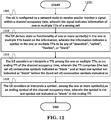
- the method includes the UE is configured by a network node to receive and/or monitor a signal within a channel occupancy time, wherein the signal indicates information of one or multiple TTIs (Transmission Time Interval) of a serving cell.
- the method further includes the UE derives state or functionality of one or more symbol(s) in the one or multiple TTIs based on the information, wherein the information indicates a symbol in the one or multiple TTIs to be any of "downlink", “uplink”, “flexible”, or "blank”.
- the method also includes the UE derives or is indicated that at least one set of consecutive symbol(s) are indicated as "blank”. Furthermore, the method includes the UE prevents from or is not required to perform reception for (dynamically) indicated or configured physical DL (Downlink) channel or RS (Reference Signal) within the set of consecutive symbols indicated as “blank”. In addition, the method includes the UE prevents from or is not required to perform transmission for (dynamically) indicated or configured physical UL (Uplink) channel or RS within the set of consecutive symbols indicated as "blank”. Also, the method includes the UE being allowed to perform a channel access procedure or LBT (Listen Before Talk) scheme within the set of consecutive symbols indicated as "blank”.
- LBT Listen Before Talk
- Wireless communication systems are widely deployed to provide various types of communication such as voice, data, and so on. These systems may be based on code division multiple access (CDMA), time division multiple access (TDMA), orthogonal frequency division multiple access (OFDMA), 3GPP LTE (Long Term Evolution) wireless access, 3GPP LTE-A or LTE-Advanced (Long Term Evolution Advanced), 3GPP2 UMB (Ultra Mobile Broadband), WiMax, 3GPP NR (New Radio), or some other modulation techniques.
- CDMA code division multiple access
- TDMA time division multiple access
- OFDMA orthogonal frequency division multiple access
- 3GPP LTE Long Term Evolution
- 3GPP LTE-A or LTE-Advanced Long Term Evolution Advanced
- 3GPP2 UMB User Mobile Broadband
- WiMax Wireless Broadband
- 3GPP NR New Radio
- the exemplary wireless communication systems devices described below may be designed to support one or more standards such as the standard offered by a consortium named "3rd Generation Partnership Project” referred to herein as 3GPP, including: Final Report of 3GPP TSG RAN WG1 #92bis v1.0.0 (Sanya, China, 16th - 20th April 2018 ); Draft Report of 3GPP TSG RAN WG1 #93 v0.2.0 (Busan, South Korea, 21st - 25th May 2018 ); TS 37.213 v15.0.0, "Physical layer procedures for shared spectrum channel access "; TS 38.211 V15.2.0, “Physical channels and modulation "; TS 38.212 V15.2.0, “Multiplexing and channel coding "; TS 38.213 V15.2.0, “Physical layer procedures for control "; and TS 38.331 V15.2.1, " Radio Resource Control (RRC) protocol specification ".
- RRC Radio Resource Control
- FIG. 1 shows a multiple access wireless communication system according to one embodiment of the invention.
- An access network 100 includes multiple antenna groups, one including 104 and 106, another including 108 and 110, and an additional including 112 and 114. In FIG. 1 , only two antennas are shown for each antenna group, however, more or fewer antennas may be utilized for each antenna group.
- Access terminal 116 is in communication with antennas 112 and 114, where antennas 112 and 114 transmit information to access terminal 116 over forward link 120 and receive information from access terminal 116 over reverse link 118.
- Access terminal (AT) 122 is in communication with antennas 106 and 108, where antennas 106 and 108 transmit information to access terminal (AT) 122 over forward link 126 and receive information from access terminal (AT) 122 over reverse link 124.
- communication links 118, 120, 124 and 126 may use different frequency for communication.
- forward link 120 may use a different frequency then that used by reverse link 118.
- antenna groups each are designed to communicate to access terminals in a sector of the areas covered by access network 100.
- the transmitting antennas of access network 100 may utilize beamforming in order to improve the signal-to-noise ratio of forward links for the different access terminals 116 and 122. Also, an access network using beamforming to transmit to access terminals scattered randomly through its coverage causes less interference to access terminals in neighboring cells than an access network transmitting through a single antenna to all its access terminals.
- An access network may be a fixed station or base station used for communicating with the terminals and may also be referred to as an access point, a Node B, a base station, an enhanced base station, an evolved Node B (eNB), a network node, a network, or some other terminology.
- An access terminal may also be called user equipment (UE), a wireless communication device, terminal, access terminal or some other terminology.
- FIG. 2 is a simplified block diagram of an embodiment of a transmitter system 210 (also known as the access network) and a receiver system 250 (also known as access terminal (AT) or user equipment (UE)) in a MIMO system 200.
- a transmitter system 210 also known as the access network
- a receiver system 250 also known as access terminal (AT) or user equipment (UE)
- traffic data for a number of data streams is provided from a data source 212 to a transmit (TX) data processor 214.
- TX transmit
- each data stream is transmitted over a respective transmit antenna.
- TX data processor 214 formats, codes, and interleaves the traffic data for each data stream based on a particular coding scheme selected for that data stream to provide coded data.
- the coded data for each data stream may be multiplexed with pilot data using OFDM techniques.
- the pilot data is typically a known data pattern that is processed in a known manner and may be used at the receiver system to estimate the channel response.
- the multiplexed pilot and coded data for each data stream is then modulated (i.e., symbol mapped) based on a particular modulation scheme (e.g., BPSK, QPSK, M-PSK, or M-QAM) selected for that data stream to provide modulation symbols.
- a particular modulation scheme e.g., BPSK, QPSK, M-PSK, or M-QAM
- the data rate, coding, and modulation for each data stream may be determined by instructions performed by processor 230.
- TX MIMO processor 220 may further process the modulation symbols (e.g., for OFDM).
- TX MIMO processor 220 then provides N T modulation symbol streams to N T transmitters (TMTR) 222a through 222t.
- TMTR TX MIMO processor 220 applies beamforming weights to the symbols of the data streams and to the antenna from which the symbol is being transmitted.
- Each transmitter 222 receives and processes a respective symbol stream to provide one or more analog signals, and further conditions (e.g., amplifies, filters, and upconverts) the analog signals to provide a modulated signal suitable for transmission over the MIMO channel.
- N T modulated signals from transmitters 222a through 222t are then transmitted from N T antennas 224a through 224t, respectively.
- the transmitted modulated signals are received by N R antennas 252a through 252r and the received signal from each antenna 252 is provided to a respective receiver (RCVR) 254a through 254r.
- Each receiver 254 conditions (e.g., filters, amplifies, and downconverts) a respective received signal, digitizes the conditioned signal to provide samples, and further processes the samples to provide a corresponding "received" symbol stream.
- An RX data processor 260 then receives and processes the N R received symbol streams from N R receivers 254 based on a particular receiver processing technique to provide N T "detected" symbol streams.
- the RX data processor 260 then demodulates, deinterleaves, and decodes each detected symbol stream to recover the traffic data for the data stream.
- the processing by RX data processor 260 is complementary to that performed by TX MIMO processor 220 and TX data processor 214 at transmitter system 210.
- a processor 270 periodically determines which pre-coding matrix to use (discussed below). Processor 270 formulates a reverse link message comprising a matrix index portion and a rank value portion.
- the reverse link message may comprise various types of information regarding the communication link and/or the received data stream.
- the reverse link message is then processed by a TX data processor 238, which also receives traffic data for a number of data streams from a data source 236, modulated by a modulator 280, conditioned by transmitters 254a through 254r, and transmitted back to transmitter system 210.
- the modulated signals from receiver system 250 are received by antennas 224, conditioned by receivers 222, demodulated by a demodulator 240, and processed by a RX data processor 242 to extract the reserve link message transmitted by the receiver system 250.
- Processor 230 determines which pre-coding matrix to use for determining the beamforming weights then processes the extracted message.
- FIG. 3 shows an alternative simplified functional block diagram of a communication device according to one embodiment of the invention.
- the communication device 300 in a wireless communication system can be utilized for realizing the UEs (or ATs) 116 and 122 in FIG. 1 or the base station (or AN) 100 in FIG. 1 , and the wireless communications system is preferably the NR system.
- the communication device 300 may include an input device 302, an output device 304, a control circuit 306, a central processing unit (CPU) 308, a memory 310, a program code 312, and a transceiver 314.
- the control circuit 306 executes the program code 312 in the memory 310 through the CPU 308, thereby controlling an operation of the communications device 300.
- the communications device 300 can receive signals input by a user through the input device 302, such as a keyboard or keypad, and can output images and sounds through the output device 304, such as a monitor or speakers.
- the transceiver 314 is used to receive and transmit wireless signals, delivering received signals to the control circuit 306, and outputting signals generated by the control circuit 306 wirelessly.
- the communication device 300 in a wireless communication system can also be utilized for realizing the AN 100 in FIG. 1 .
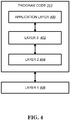
- FIG. 4 is a simplified block diagram of the program code 312 shown in FIG. 3 in accordance with one embodiment of the invention.
- the program code 312 includes an application layer 400, a Layer 3 portion 402, and a Layer 2 portion 404, and is coupled to a Layer 1 portion 406.
- the Layer 3 portion 402 generally performs radio resource control.
- the Layer 2 portion 404 generally performs link control.
- the Layer 1 portion 406 generally performs physical connections.
- the Final Report of 3GPP TSG RAN WG1 #92bis v1.0.0 includes the following agreements:
- the Draft Report of 3GPP TSG RAN WG1 #93 v0.2.0 includes the following agreements:
- 3GPP TS 37.213 includes the following description related to channel access procedure:
- An eNB operating LAA Scell(s) shall perform the channel access procedures described in this sub clause for accessing the channel(s) on which the LAA Scell(s) transmission(s) are performed.
- the eNB may transmit a transmission including PDSCH/PDCCH/EPDCCH on a carrier on which LAA Scell(s) transmission(s) are performed , after first sensing the channel to be idle during the slot durations of a defer duration T d ; and after the counter N is zero in step 4.
- the counter N is adjusted by sensing the channel for additional slot duration(s) according to the steps below:
- the eNB may transmit a transmission including PDSCH/PDCCH/EPDCCH on the carrier, if the channel is sensed to be idle at least in a slot duration T sl when the eNB is ready to transmit PDSCH/PDCCH/EPDCCH and if the channel has been sensed to be idle during all the slot durations of a defer duration T d immediately before this transmission.
- the eNB proceeds to step 1 after sensing the channel to be idle during the slot durations of a defer duration T d .
- a slot duration T sl is considered to be idle if the eNB senses the channel during the slot duration, and the power detected by the eNB for at least 4us within the slot duration is less than energy detection threshold X Thresh . Otherwise, the slot duration T sl is considered to be busy.
- CW min, p ⁇ CW p ⁇ CW max, p is the contention window.
- CW p adjustment is described in sub clause 4.1.4.
- CW min, p and CW max, p are chosen before step 1 of the procedure above.
- m p , CW min, p , and CW max, p are based on channel access priority class associated with the eNB transmission, as shown in Table 4.1.1-1.
- the eNB shall not decrement N during the slot duration(s) overlapping with discovery signal transmission.
- the eNB shall not continuously transmit on a carrier on which the LAA Scell(s) transmission(s) are performed, for a period exceeding T m cot, p as given in Table 4.1.1-1.
- the channel is considered to be idle for T js if it is sensed to be idle during the during the slot durations of T js .
- the channel is considered to be idle for T drs if it is sensed to be idle during the slot durations of T drs .
- the channel is considered to be idle for T pdcch if it is sensed to be idle during the slot durations of T pdcch .
- An eNB can access multiple carriers on which LAA Scell(s) transmission(s) are performed, according to one of the Type A or Type B procedures described in this Subclause.
- N c i The counter N described in Subclause 4.1.1 is determined for each carrier c i and is denoted as N c i .
- N c i is maintained according to Subclause 4.1.5.1.1 or 4.1.5.1.2.
- Counter N as described in Subclause 4.1.1 is independently determined for each carrier c i and is denoted as N c i .
- the eNB when the eNB ceases transmission on any one carrier c j ⁇ C , for each carrier c i ⁇ c j , the eNB can resume decrementing N c i when idle slots are detected either after waiting for a duration of 4. T sl , or after reinitialising N c i .
- a carrier c j ⁇ C is selected by the eNB as follows
- the eNB shall not continuously transmit on a carrier c i ⁇ c j , c i ⁇ C , for a period exceeding T m cot, p as given in Table 4.1.1-1, where the value of T m cot, p is determined using the channel access parameters used for carrier c j .
- a single CW p value is maintained for the set of carriers C .
- step 2 of the procedure described in sub clause 4.1.3 is modified as follows
- a CW p value is maintained independently for each carrier c i ⁇ C using the procedure described in Subclause 4.1.3.
- CW p value of carrier c j 1 ⁇ C is used, where c j 1 is the carrier with largest CW p among all carriers in set C .
- a UE and a eNB scheduling UL transmission(s) for the UE shall perform the procedures described in this sub clause for the UE to access the channel(s) on which the LAA Scell(s) transmission(s) are performed.
- the UE can access a carrier on which LAA Scell(s) UL transmission(s) are performed according to one of Type 1 or Type 2 UL channel access procedures.
- Type 1 channel access procedure is described in sub clause 4.2.1.1.
- Type 2 channel access procedure is described in sub clause 4.2.1.2.
- an UL grant scheduling a PUSCH transmission indicates Type 1 channel access procedure
- the UE shall use Type 1 channel access procedure for transmitting transmissions including the PUSCH transmission unless stated otherwise in this sub clause.
- a UE shall use Type 1 channel access procedure for transmitting transmissions including the PUSCH transmission on autonomous UL resources unless stated otherwise in this sub clause.
- Type 2 channel access procedure the UE shall use Type 2 channel access procedure for transmitting transmissions including the PUSCH transmission unless stated otherwise in this sub clause.
- the UE shall use Type 1 channel access procedure for transmitting SRS transmissions not including a PUSCH transmission.
- UL channel access priority class p 1 is used for SRS transmissions not including a PUSCH.
- the UE shall attempt to make SRS transmission in subframe n according to uplink channel access procedures specified for SRS transmission.
- the UE scheduled to transmit transmissions including PUSCH in a set subframes n 0 , n 1 , ...,n w -1 using PDCCH DCI Format 0B/4B and if the UE cannot access the channel for a transmission in subframe n k , the UE shall attempt to make a transmission in subframe n k +1 according to the channel access type indicated in the DCI, where k ⁇ ⁇ 0,1,... w -2 ⁇ , and w is the number of scheduled subframes indicated in the DCI.
- the UE may continue transmission in subframes after n k where k ⁇ ⁇ 0,1, ⁇ w -1 ⁇ .
- the UE is not expected to be indicated with different channel access types for the transmissions in those subframes.
- the number of attempts the UE should make for the transmission is limited to w +1, where w is the number of scheduled subframes indicated in the DCI.
- the UE may transmit in a later subframe n k2 , k 2 ⁇ ⁇ 1, ⁇ w- 1 ⁇ using Type 2 channel access procedure.
- the UE may transmit in a later subframe n k2 , k 2 ⁇ ⁇ 1, ⁇ w -1 ⁇ using Type 1 channel access procedure with the UL channel access priority class indicated in the DCI corresponding to subframe n k2 .
- the UE receives an UL grant and the DCI indicates a PUSCH transmission starting in subframe n using Type 1 channel access procedure, and if the UE has an ongoing Type 1 channel access procedure before subframe n .
- the UE shall terminate the ongoing PUSCH transmissions using the autonomous UL at least one subframe before the UL transmission according to the received UL grant.
- the UE may transmit UL transmission(s) according to the received UL grant from subframe n without a gap, if the priority class value of the performed channel access procedure is larger than or equal to priority class value indicated in the UL grant, and the autonomous UL transmission in the subframe preceding subframe n shall end at the last OFDM symbol of the subframe regardless of the higher layer parameter AulEndingPosition.
- the sum of the lengths of the autonomous UL transmission(s) and the scheduled UL transmission(s) shall not exceed the maximum channel occupancy time corresponding to the priority class value used to perform the autonomous uplink channel access procedure. Otherwise, the UE shall terminate the ongoing autonomous UL transmission at least one subframe before the start of the UL transmission according to the received UL grant on the same carrier.
- a eNB may indicate Type 2 channel access procedure in the DCI of an UL grant scheduling transmission(s) including PUSCH on a carrier in subframe n when
- the eNB shall schedule UL transmissions between t 0 and t 0 + T co in contiguous subframes if they can be scheduled contiguously.
- the UE may use Type 2 channel access procedure for the UL transmission.
- the eNB indicates Type 2 channel access procedure for the UE in the DCI, the eNB indicates the channel access priority class used to obtain access to the channel in the DCI.
- the UE may transmit the transmission using Type 1 channel access procedure after first sensing the channel to be idle during the slot durations of a defer duration T d ; and after the counter N is zero in step 4.
- the counter N is adjusted by sensing the channel for additional slot duration(s) according to the steps described below.
- the UE may transmit a transmission including PUSCH or SRS on the carrier, if the channel is sensed to be idle at least in a slot duration T sl when the UE is ready to transmit the transmission including PUSCH or SRS, and if the channel has been sensed to be idle during all the slot durations of a defer duration T d immediately before the transmission including PUSCH or SRS.
- the UE proceeds to step 1 after sensing the channel to be idle during the slot durations of a defer duration T d .
- a slot duration T sl is considered to be idle if the UE senses the channel during the slot duration, and the power detected by the UE for at least 4 us within the slot duration is less than energy detection threshold X Thresh . Otherwise, the slot duration T sl is considered to be busy.
- CW min, p ⁇ CW p ⁇ CW max, p is the contention window.
- CW p adjustment is described in sub clause 4.2.2.
- CW min, p and CW max, p are chosen before step 1 of the procedure above.
- m p , CW min, p , and CW max, p are based on channel access priority class signalled to the UE, as shown in Table 4.2.1-1.
- the channel is considered to be idle for T short_ul if it is sensed to be idle during the slot durations of T short_ul .
- 3GPP TS 38.211 includes the following description:
- slots are numbered n s ⁇ ⁇ 0 , ... , N slot subframe , ⁇ ⁇ 1 in increasing order within a subframe and n s , f ⁇ ⁇ 0 , ... , N slot frame , ⁇ ⁇ 1 in increasing order within a frame.
- N symb slot consecutive OFDM symbols in a slot where N symb slot depends on the cyclic prefix as given by Tables 4.3.2-1 and 4.3.2-2.
- the start of slot n s ⁇ in a subframe is aligned in time with the start of OFDM symbol n s ⁇ N symb slot in the same subframe.
- OFDM symbols in a slot can be classified as 'downlink', 'flexible', or 'uplink'. Signaling of slot formats is described in subclause 11.1 of [5, TS 38.213].
- the UE shall assume that downlink transmissions only occur in 'downlink' or 'flexible' symbols.
- the UE In a slot in an uplink frame, the UE shall only transmit in 'uplink' or 'flexible' symbols.
- a UE not capable of full-duplex communication is not expected to transmit in the uplink earlier than N Rx-Tx T c , after the end of the last received downlink symbol in the same cell where N Rx-Tx is given by [TS 38.101].
- 3GPP TS 38.212 includes the following description:
- DCI format 2_0 is used for notifying the slot format.
- DCI format 2_0 is configurable by higher layers up to 128 bits, according to Subclause 11.1.1 of [5, TS 38.213].
- 3GPP TS 38.213 includes the following description:
- a set of PDCCH candidates for a UE to monitor is defined in terms of PDCCH search space sets.
- a search space set can be a common search space set or a UE-specific search space set.
- a UE monitors PDCCH candidates in one or more of the following search spaces sets
- the UE For each DL BWP configured to a UE in a serving cell, the UE is provided by higher layers with S ⁇ 10 search space sets where, for each search space set from the S search space sets, the UE is provided the following by higher layer parameter SearchSpace :
- a slot format includes downlink symbols, uplink symbols, and flexible symbols.
- This subclause applies for a serving cell that is included in a set of serving cells configured to a UE by higher layer parameters slotFormatCombToAddModList and slotFormatCombToReleaseList.
- a UE is configured by higher layers with parameter SlotFormatIndicator, the UE is provided with a SFI-RNTI by higher layer parameter sfi-RNTI and with a payload size of DCI format 2_0 by higher layer parameter dci-PayloadSize.
- the UE is also provided in one or more serving cells with a configuration for a search space set s and a corresponding control resource set p for monitoring M p , s L SFI PDCCH candidates for DCI format 2_0 with a CCE aggregation level of L SFI CCEs as described in Subclause 10.1.
- the M p , s L SFI PDCCH candidates are the first M p , s L SFI PDCCH candidates for CCE aggregation level L SFI for search space set s in control resource set p .
- the UE For each serving cell in the set of serving cells, the UE can be provided:
- a SFI-index field value in a DCI format 2_0 indicates to a UE a slot format for each slot in a number of slots for each DL BWP or each UL BWP starting from a slot where the UE detects the DCI format 2_0.
- the number of slots is equal to or larger than a PDCCH monitoring periodicity for DCI format 2_0.
- the SFI-index field includes log 2 (maxSFIindex) bits where maxSFIindex is the maximum value of the values provided by corresponding higher layer parameters slotFormatCombinationId.
- a slot format is identified by a corresponding format index as provided in Table 11.1.1-1 where 'D' denotes a downlink symbol, 'U' denotes an uplink symbol, and 'F' denotes a flexible symbol.
- the UE For unpaired spectrum operation for a UE on a serving cell, the UE is provided by higher layer parameter subcarrierSpacing a reference subcarrier spacing configuration of ⁇ SFI for each slot format in a combination of slot formats indicated by a SFI-index field value in DCI format 2_0.
- the UE expects that for a reference subcarrier spacing configuration of ⁇ SFI and for an active DL BWP and UL BWP pair with subcarrier spacing configuration of ⁇ , it is ⁇ ⁇ ⁇ SFI .
- Each slot format in the combination of slot formats indicated by the SFI-index field value in DCI format 2_0 is applicable to 2 ( ⁇ - ⁇ SFI ) consecutive slots in the active DL BWP and UL BWP pair where the first slot starts at a same time as a first slot for the reference subcarrier spacing configuration of ⁇ SFI and each downlink or flexible or uplink symbol for the reference subcarrier spacing configuration of ⁇ SFI corresponds to 2 ( ⁇ - ⁇ SFI ) consecutive downlink or flexible or uplink symbols for the subcarrier spacing configuration ⁇ .
- the UE is provided with a reference subcarrier spacing configuration of ⁇ SFI,DL so that for an active DL BWP with subcarrier spacing configuration of ⁇ DL , it is ⁇ DL ⁇ ⁇ SFI,DL .
- the UE is provided with a reference subcarrier spacing configuration of ⁇ SFI, UL so that for an active UL BWP with subcarrier spacing configuration of ⁇ UL , it is ⁇ UL ⁇ ⁇ SFI, UL .
- Each slot format for a combination of slot formats indicated by the SFI-index field value in DCI format 2_0 for the reference DL BWP, by indicating a value for slotFormatCombinationId that is mapped to a value of slotFormats in slotFormatCombination, is applicable to 2 ( ⁇ DL - ⁇ SFI,DL ) consecutive slots for the active DL BWP where the first slot starts at a same time as a first slot in the reference DL BWP and each downlink or flexible symbol for the reference subcarrier spacing configuration of ⁇ SFI,DL corresponds to 2 ( ⁇ DL - ⁇ SFI,DL ) consecutive downlink or flexible symbols for the subcarrier spacing configuration ⁇ DL .
- Each slot format for the combination of slot formats for the reference UL BWP is applicable to 2 ( ⁇ UL - ⁇ SFI,UL ) consecutive slots for the active UL BWP where the first slot starts at a same time as a first slot in the reference UL BWP and each uplink or flexible symbol for the reference subcarrier spacing configuration of ⁇ SFI,UL corresponds to 2 ( ⁇ UL - ⁇ SFI,UL ) consecutive uplink or flexible symbols for the subcarrier spacing configuration ⁇ UL .
- the UE expects to be provided with a reference subcarrier spacing configuration of ⁇ SFI,SUL so that for an active UL BWP in the second UL carrier with subcarrier spacing configuration of ⁇ SUL , it is ⁇ SUL ⁇ ⁇ SFI,SUL .
- Each slot format for a combination of slot formats indicated by the SFI-index field in DCI format 2_0 for the reference first UL carrier is applicable to 2 ( ⁇ - ⁇ SFI ) consecutive slots for the active DL BWP and UL BWP pair in the first UL carrier where the first slot starts at a same time as a first slot in the reference first UL carrier.
- Each slot format for the combination of slot formats for the reference second UL carrier is applicable to 2 ( ⁇ SUL- ⁇ SFI,SUL ) consecutive slots for the active UL BWP in the second UL carrier where the first slot starts at a same time as a first slot in the reference second UL carrier.
- 3GPP TS 38.331 includes the following description:
- the IE SlotFormatCombinationsPerCell is used to configure the SlotFormatCombinations applicable for one serving cell.
- L1 parameter 'cell-to-SFI' corresponds to L1 parameter 'cell-to-SFI' (see 38.213, section 11.1.1).
- the IE SlotFormatIndicator is used to configure monitoring a Group-Common-PDCCH for Slot-Format-Indicators (SFI).
- NR New RAT/Radio
- Beam forming technology and wider bandwidth used compared to LTE bring a high enhancement on traffic rate.
- NR technology is focusing on transmission/reception in licensed spectrum.
- For a higher traffic date rate foreseen to be used for service demand in the future, NR applied in unlicensed spectrum also shows appealing and plays an important role, as LAA in LTE.
- a clear channel assessment or an LBT (Listen Before Talk) procedure to make sure that the unlicensed channel is clear or idle, which means no other wireless node(s) are transmitting in the unlicensed spectrum. If the clear channel assessment or the LBT procedure is completed successfully, the wireless node can transmit in the unlicensed spectrum or channel for a channel occupancy time. Since the timing for completing successfully a clear channel assessment or an LBT procedure is not fixed, the slot structure of slots within the channel occupancy time, the starting slot, and the ending slot and/or position of the ending symbol is also uncertain until a clear channel assessment or an LBT procedure is completed successfully.
- one of issues needed to tackle is that how to indicate UE the structure of TTIs or slot structure within a channel occupancy time.
- which slot is ending slot (i.e. last slot in a channel occupancy time)
- the position of ending symbol i.e. the last symbol in the ending slot.
- the present invention discusses how to indicate information of an ending slot and/or ending symbol.
- SFI Slot Format Indication
- UE may detect an SFI-DCI (SFI-Downlink Control Information), which is a DCI indicating a (preconfigured or predetermined) slot format combination for the serving cell, e.g. DCI format 2_0.
- SFI-DCI SFI-Downlink Control Information
- the slot format combination may comprise one or more slot format values for one or more slots.
- Each slot format value is predetermined or preconfigured to indicate transmission direction or functionality of each symbol within a slot.
- a slot format value may indicate a symbol within a slot as "D", "U” and "F", which means downlink symbol, uplink symbol and flexible symbol respectively.
- An SFI-DCI can indicate a slot format combination for a group of UE, which means the indicated slot format combination can be applied for the group of UE.
- subcarrier spacing (SCS) configurations of active BWP (Bandwidth Part) of each UE among the group may be different. Since time length of a symbol or slot is associated with SCS, different understanding of indicated time duration of the indicated slot format combination may occur if each UE among the group interprets the slot format combination using its own SCS configuration of active BWP.
- a reference SCS is configured for each UE to interpret the slot format combination, that is, each UE receiving a same slot format combination value uses a same SCS value (i.e. reference SCS) to interpret the slot format combination.
- the SFI indication method Since the SFI indication method has been introduced to indicate slot structure in licensed spectrum, it should be also suitable for indicating slot structure of ending slot within a channel occupancy time in unlicensed spectrum. However, for indicating ending slot and/or ending symbol within a channel occupancy time, one issue would occur if using existing SFI indication method in NR Rel. 15. Since in NR Rel. 15, there is no concept for ending slot and ending symbol in licensed spectrum. The existing SFI structure may not provide the purpose for indicating ending slot and/or ending symbol.
- a slot for reference SCS is denoted as a reference slot and a symbol in a reference slot is denoted as reference symbol.
- reference SCS is 30 kHz
- 1 ms may comprise two reference slots, which means 1 ms comprises 28 reference symbols.
- UE is not able to realize position of ending symbol or position of a symbol after which UE considers a channel occupancy time is ended; similarly, network node is unable to indicate UE the accurate ending symbol or a symbol after which UE should consider a channel occupancy time is ended.
- the following general solutions or embodiments are provided, which can be at least (but not limited to) used to handle: (i) at least for how network node can indicate UE the position, functionality and/or transmission direction of an ending symbol and/or ending slot, (ii) for UE to realize the position, functionality and/or transmission direction of an ending symbol and/or ending slot.
- the UE may not receive configured data channel (and/or transmit configured data channel) until the UE detects next channel occupancy by network node or until the UE receives a transmission from network node or until the UE performs a clear channel assessment or a LBT procedure (successfully). Furthermore, after (the end of) an ending slot, the UE may not receive configured RS for channel measurement (and/or transmit configured RS for channel measurement) until the UE detects next channel occupancy by network node or until the UE receives a transmission from network node or until the UE performs a clear channel assessment or a LBT procedure (successfully).
- the UE may not monitor and/or detect configured CORESET(s) (Control Resource Set) until the UE detects next channel occupancy by network node or until the UE receives a transmission from network node or until the UE performs a clear channel assessment or a LBT procedure (successfully). Also, after (the end of) a ending slot, the UE may not transmit PRACH (Physical Random Channel) on a configured PRACH transmission occasion until the UE detects next channel occupancy by network node or until the UE receives a transmission from network node or until the UE performs a clear channel assessment or an LBT procedure (successfully).
- PRACH Physical Random Channel
- the UE may not receive configured data channel (and/or transmit configured data channel) until the UE detects next channel occupancy by network node or until the UE receives a transmission from network node or until the UE performs a clear channel assessment or a LBT procedure (successfully). Furthermore, after (the end of) a ending symbol, the UE may not receive configured RS (Reference Signal) for channel measurement (and/or transmit configured RS for channel measurement) until the UE detects next channel occupancy by network node or until the UE receives a transmission from network node or until the UE performs a clear channel assessment or a LBT procedure (successfully).
- RS Reference Signal
- the UE may not monitor and/or detect configured CORESET(s) until the UE detects next channel occupancy by network node or until the UE receives a transmission from network node or until the UE performs a clear channel assessment or a LBT procedure (successfully). Also, after (the end of) a ending symbol, the UE may not transmit PRACH on configured PRACH transmission occasion until the UE detects next channel occupancy by network node or until the UE receives a transmission from network node or until the UE performs a clear channel assessment or a LBT procedure (successfully).
- a channel occupancy time could be a time duration where a wireless node transmits without performing another one channel access procedure or another one channel access procedure with random access mechanism after the wireless node performs a channel access procedure or LBT scheme (successfully).
- a wireless node could perform transmission and/or reception (continuously).
- a wireless node may assume transmission/reception (on a time duration) is the same as licensed band or spectrum.
- a wireless node may assume slot format or frame structure could be determined based on RRC signaling(s), e.g.
- a wireless node may perform transmission/reception same as licensed band or spectrum.
- a channel occupancy could mean that a wireless node performs transmission in unlicensed spectrum and/or unlicensed channel for channel occupancy time after a successful channel access procedure and/or LBT scheme.
- a UE could detect a channel occupancy (time) from or by the network node means the UE detects or realizes that the network node (currently) is allowed to perform transmission (continuously) for a time period (channel occupancy time) after a successfully channel access procedure and/or LBT scheme.
- a network node could detect a channel occupancy (time) from or by a serving UE means network node detects or realizes that the serving UE (currently) is allowed to perform transmission (continuously) for a time period (channel occupancy time) after a successfully channel access procedure and/or LBT scheme.
- a symbol for a SCS (Service Capability Server) or a symbol based on a SCS could mean that time length of the symbol may be based on the SCS.
- a slot for a SCS or a slot based on a SCS could mean that time length of the slot may be based on the SCS.
- a slot for a TTI or a slot based on a SCS could mean that time length of the TTI may be based on the SCS.
- An unlicensed cell may be a serving cell operated or located in unlicensed spectrum.
- a slot for reference SCS can be denoted as a reference slot.
- a symbol for reference SCS in a reference slot can be denoted as reference symbol.
- a TTI for reference SCS in a reference slot can be denoted as reference TTI.
- Embodiment 1 - A UE (is configured to) receive and/or monitor a slot format related DCI indicating or carrying a slot format combination, wherein the slot format combination comprises one or more slot format values.
- the UE could receive and/or monitor the slot format related DCI within a channel occupancy time.
- the slot format combination may be for a channel occupancy time or for an unlicensed cell. More specifically, the slot format combination may be for the channel occupancy time in the unlicensed cell.
- one or more slot format values in the slot format combination may be used to indicated information of one or more TTIs (Transmission Time Interval) or slot.
- a slot may be referred to or replaced with a TTI (or other type of TTI, e.g. symbol, mini-slot, subframe, frame).
- the slot format related DCI may be referred to or replaced with a signal, wherein the signal could be for indicating information of one or multiple TTIs of the unlicensed cell.
- the information of one or multiple TTIs could be slot format combination.
- the information of one or multiple TTIs could be one or multiple slot format values (comprised in slot format combination), and vice versa.
- the UE could receive and/or monitor the slot format related DCI in unlicensed spectrum.
- the UE could receive and/or monitor the slot format related DCI in licensed spectrum.
- the slot format combination could be applied to an unlicensed spectrum.
- the slot format combination could be applied to a licensed spectrum.
- the UE could receive and/or monitor the slot format related DCI in licensed spectrum, wherein the slot format related DCI is applied in unlicensed spectrum.
- the one or more slot format values comprised in the slot format combination may indicate slot formats for slots within the channel occupancy time.
- the one or more slot format values comprised in the slot format combination may also indicate transmission direction and/or functionality for each symbol (or most of symbols) in slots within the channel occupancy time.
- the one or more slot format values comprised in the slot format combination may also (at least) indicate a symbol is "downlink” or "uplink” or “flexible” or “blank".
- the one or more slot format values comprised in the slot format combination may (at least) indicate a symbol is "downlink” or “uplink” or “flexible”.
- the one or more slot format values comprised in the slot format combination may (at least) indicate a symbol is "downlink” or "uplink” or “flexible” or “blank”.
- one slot format value in the slot format combination may indicate a symbol is as "blank”.
- the slot format combination is for licensed spectrum, the one or more slot format values comprised in the slot format combination does not or is not allowed to indicate a symbol is "blank”. If the slot format combination is for licensed spectrum, the UE may not expect to indicate a symbol as "blank”.
- a symbol is indicated as "downlink”, the symbol could be for downlink transmission. If a symbol is indicated as “uplink”, the symbol could be for uplink transmission. If a symbol is indicated as “flexible”, the symbol could be for either downlink transmission or uplink transmission is determined based on (further) indicating from network node, if any.
- the UE may not transmit or receive on the symbol if no (further) indicating from network node. If a symbol is indicated as “blank”, the UE may not perform transmission or reception on the symbol. Furthermore, if a symbol is indicated as “blank”, the UE may not transmit physical channel and/or RS indicated (or configured) by network node on the symbol, and/or may not receive physical channel and/or RS indicated (or configured) by network node on the symbol. Preferably, if a symbol is indicated as "blank”, the UE may not receive physical channel and/or RS indicated (or configured) by network node on the symbol, except for an indicator or signal.
- the UE may not receive physical channel and/or RS indicated (or configured) by network node on the symbol, except for performing a clear channel assessment and/or LBT scheme.
- the UE may perform a clear channel assessment and/or LBT scheme on the symbol.
- blank can be replaced with or referred to "reserved”, “empty”, “unoccupied”, or other names, not limited to “blank”.
- a symbol indicated as “blank” can be used to derive or indicate an ending slot and/or symbol in the channel occupancy time.
- the indicator or signal may indicate the UE that network node occupy an unlicensed channel. Furthermore, the indicator or signal may indicate the UE that network node performs a clear channel assessment and/or LBT scheme (successfully).
- downlink can be denoted as “D”
- uplink can be denoted as “U”
- flexible can be denoted as “F”
- bladenk can be denoted as "B”.
- the UE could interpret slot format values comprised in the slot format combination at least based on a reference SCS.
- the UE could interpret slot format values comprised in the slot format combination at least based on a SCS configured for active DL BWP.
- An SCS configured for active DL BWP can be denoted as an actual DL SCS.
- the UE could interpret slot format values comprised in the slot format combination at least based on the reference SCS and the actual DL SCS.
- the UE could derive slot structure of an ending slot within the channel occupancy time from a slot format value indicated or carried in the slot format combination.
- the slot format value may be the last slot format value indicated in the slot format combination.
- the UE could also derive which one slot is the ending slot within the channel occupancy time from the slot format value.
- the UE could derive transmission direction and/or functionality of each symbol (or some of symbols) in the ending slot within the channel occupancy time at least from the slot format value.
- the UE could consider or interpret that a slot, with one of symbols indicated as "B" in the slot format value or the slot format combination, is the ending slot (within the channel occupancy time).
- the UE could also consider or interpret that a slot for the reference SCS, with one of symbols indicated as "B” in the slot format value or the slot format combination, is the ending slot (within the channel occupancy time).
- the UE could consider or interpret that a slot for the actual DL SCS, with one of symbols indicated as "B”, is the ending slot (within the channel occupancy time).
- the UE could consider or interpret that a slot for the actual DL SCS, with one of symbols corresponding to a symbol for the reference SCS indicated as "B” in the slot format value, as the ending slot (within the channel occupancy time).
- the UE could consider or interpret that a slot, with one of symbols indicated as "B" in the slot format combination, is the ending slot (within the channel occupancy time), unless receiving another one slot format combination for the unlicensed cell.
- the UE could also consider or interpret that a slot for the reference SCS, with one of symbols indicated as "B” in the slot format combination, is the ending slot (within the channel occupancy time), unless receiving another one slot format combination for the unlicensed cell.
- the UE could consider or interpret that a slot for the actual DL SCS, with one of symbols indicated as "B”, is the ending slot (within the channel occupancy time), unless receiving another one slot format combination for the unlicensed cell.
- the UE could consider or interpret that a slot for the actual DL SCS, with one of symbols corresponding to a symbol for the reference SCS indicated as "B" in the slot format combination, as the ending slot (within the channel occupancy time), unless receiving another one slot format combination for the unlicensed cell.
- the UE could consider or interpret that a slot, with one of symbols indicated as "B" in the last slot format value in the slot format combination, is the ending slot (within the channel occupancy time), unless receiving another one slot format combination for the unlicensed cell.
- the UE could also consider or interpret that a slot for the reference SCS, with one of symbols indicated as "B” in the last format value in the slot format combination, is the ending slot (within the channel occupancy time), unless receiving another one slot format combination for the unlicensed cell.
- the UE could consider or interpret that a slot for the actual DL SCS, with one of symbols indicated as "B" in the last format value in the slot format combination, is the ending slot (within the channel occupancy time), unless receiving another one slot format combination for the unlicensed cell.
- the UE could consider or interpret that a slot for the actual DL SCS, with one of symbols corresponding to a symbol for the reference SCS indicated as "B" in the last slot format value in the slot format combination, as the ending slot (within the channel occupancy time), unless receiving another one slot format combination for the unlicensed cell.
- the UE could derive an information of an ending symbol at least from the slot format value.
- the information of an ending symbol may comprise an indication of which symbol is the ending symbol.
- the information of an ending symbol may comprise the transmission direction and/or functionality of the ending symbol.
- the UE could consider or interpret that the last symbol, indicated as "D” or “U” or “F” in the slot format value or the slot format combination, is the ending symbol (within the channel occupancy time).
- the UE could also consider or interpret that the last symbol for the actual DL SCS, which is indicated as “D” or “U” or “F”, is the ending symbol (within the channel occupancy time).
- the UE could consider or interpret that the last symbol for the actual DL SCS, which is corresponding to the last symbol for the reference SCS indicated as "D" or "U” or “F” in the slot format value, as the ending symbol (within the channel occupancy time).
- the UE could consider or interpret that the last symbol, indicated as "D” or “U” or “F” in the slot format value or the slot format combination, is the ending symbol (within the channel occupancy time), unless receiving another one slot format combination for the unlicensed cell.
- the UE could consider or interpret that the last symbol for the actual DL SCS, which is indicated as "D” or “U” or “F”, is the ending symbol (within the channel occupancy time), unless receiving another one slot format combination for the unlicensed cell.
- the UE could also consider or interpret that the last symbol for the actual DL SCS, which is corresponding to the last symbol for the reference SCS indicated as "D" or "U” or “F” in the slot format value, as the ending symbol (within the channel occupancy time), unless receiving another one slot format combination for the unlicensed cell.
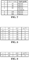
- the slot format value for reference SCS indicates "(D, D, D, F, F, F, F, D, D, D, D, D, B, B, B, B", which corresponds to two slots for the actual DL SCS: "(D, D, D, D, D, F, F, F, F, F, F, F)" and "(D, D, D, D, D, D , D , B, B, B, B, B, B, B)".
- the slot for the actual DL SCS with one of symbols indicated as "B" in the slot format value is the second slot.
- the second slot is the ending slot.
- the last symbol for the reference SCS indicated as "D” or “U” in the slot format value is the last to fourth symbol, i.e. symbol #10, which is indicated as "D" (marked as bold and italic).
- the symbols for the actual DL SCS corresponding to the symbol #10 for the reference SCS in the slot format value are the seventh and eighth symbol (symbol #6 and symbol #7) in the second corresponded slot for the actual DL SCS (marked as bold and italic). Therefore, symbol #7 in the second corresponded slot for the actual DL SCS is the last symbol for the actual DL SCS, which is corresponding to the last symbol for the reference SCS indicated as "D" or "U” in the slot format value.
- the UE considers or interprets symbol #7 (starting from symbol #0) in the second corresponded slot is the ending symbol and its transmission direction or functionality is "D".
- Embodiment 2 - A UE (is configured to) receive and/or monitor a slot format related DCI indicating or carrying a slot format combination, wherein the slot format combination comprises one or more slot format values.
- the UE could receive and/or monitor the slot format related DCI within a channel occupancy time.
- the slot format combination could be for a channel occupancy time or an unlicensed cell.
- the slot format combination could be for the channel occupancy time in the unlicensed cell.
- one or more slot format values in the slot format combination may be used to indicate information of one or more TTIs or slot.
- a slot may be referred to or replaced with a TTI (or other type of TTI, e.g. symbol, mini-slot, subframe, frame), vice versa.
- the slot format related DCI may be referred to or replaced with a signal, wherein, preferably, the signal is for indicating information of one or multiple TTIs of the unlicensed cell.
- the information of one or multiple TTIs could be slot format combination.
- the information of one or multiple TTIs could be one or multiple slot format values (comprised in slot format combination).
- the UE could receive and/or monitor the slot format related DCI in unlicensed spectrum.
- the UE could receive and/or monitor the slot format related DCI in licensed spectrum.
- the slot format combination could be applied for unlicensed spectrum.
- the slot format combination could be applied for licensed spectrum.
- the UE could receive and/or monitor the slot format related DCI in licensed spectrum, wherein the slot format related DCI is applied in unlicensed spectrum.
- the one or more slot format values comprised in the slot format combination may indicate slot formats for slots within the channel occupancy time.
- the one or more slot format values comprised in the slot format combination may also indicate transmission direction and/or functionality for each symbol (or most of symbols) in slots within the channel occupancy time.
- the one or more slot format values comprised in the slot format combination may (at least) indicate a symbol is "downlink” or “uplink” or “flexible”. If a symbol is indicated as “downlink”, the symbol could be for downlink transmission. If a symbol is indicated as “uplink”, the symbol could be for uplink transmission. If a symbol is indicated as “flexible”, the symbol could be for either downlink transmission or uplink transmission is determined based on (further) indicating from network node, if any. If a symbol is indicated as “flexible”, the UE may not transmit or receive on the symbol if no (further) indicating from network node. "Downlink” can be denoted as “D”; “uplink” can be denoted as “U”; and “flexible” can be denoted as "F”.
- the UE could interpret slot format values comprised in the slot format combination at least based on a reference SCS.
- the UE could also interpret slot format values comprised in the slot format combination at least based on a SCS configured for active DL BWP.
- a SCS configured for active DL BWP can be denoted as an actual DL SCS.
- the UE could interpret slot format values comprised in the slot format combination at least based on the reference SCS and the actual DL SCS.
- the UE could derive slot structure of an ending slot within the channel occupancy time from a slot format value indicated or carried in the slot format combination.
- the slot format value could be the last slot format value indicated in the slot format combination.
- the UE could derive which slot is the ending slot within the channel occupancy time from the slot format value.
- the UE could also derive transmission direction and/or functionality of each symbol (or some of symbols) in the ending slot within the channel occupancy time at least from the slot format value.
- the slot format value could indicate a special symbol pattern.
- the special symbol pattern could be a symbol pattern or combination that beyond the UE's capability to perform it.
- the special symbol pattern may comprise one "downlink” symbol followed by an "uplink” symbol.
- the special symbol pattern may comprise one "downlink” symbol for the reference SCS followed by an "uplink” symbol for the reference SCS.
- the special symbol pattern may comprise one "downlink” symbol for the actual SCS followed by an "uplink” symbol for the actual SCS.
- a possible example for the special symbol pattern could be "(D, U)".
- slot format value could be "(D, D, D, F, F, F, F, D, D, D , U , U, U)", wherein the special symbol pattern is marked as bold and italic.
- slot format value could be "(U, U, U, U, U, U, D , U , U, D , U , U, U, U, U, U, U)", wherein the special symbol pattern is marked as bold and italic.
- the special symbol pattern may be (only) present or indicated for unlicensed spectrum.
- the special symbol pattern may not be present or not indicated for licensed spectrum. If the slot symbol format combination is for licensed spectrum, the UE may not expect to be indicated a symbol special symbol pattern in the slot format combination.
- the UE may not transmit or receive on the symbol.
- the UE may not transmit physical channel and/or RS indicated (or configured) by network node on the symbol, and/or may not receive physical channel and/or RS indicated (or configured) by network node on the symbol.
- the UE may not receive physical channel and/or RS indicated (or configured) by network node on the symbol, except for an indicator or signal.
- the UE may not receive physical channel and/or RS indicated (or configured) by network node on the symbol, except for performing a clear channel assessment and/or LBT scheme. Furthermore, for a symbol for active DL SCS corresponding to symbol(s) for the reference SCS after the special symbol pattern, the UE may perform a clear channel assessment and/or LBT scheme on the symbol.
- the indicator or signal may indicate the UE that network node occupy an unlicensed channel.
- the indicator or signal may also indicate the UE that network node performs a clear channel assessment and/or LBT scheme (successfully).
- the UE could consider or interpret that a slot, comprising the special symbol pattern indicated in the slot format value, is the ending slot (within the channel occupancy time).
- the UE could also consider or interpret that a slot for the reference SCS, comprising the special symbol pattern indicated in the slot format value, is the ending slot (within the channel occupancy time).
- the UE could consider or interpret that a slot for the actual DL SCS, comprising the special symbol pattern indicated in the slot format value, is the ending slot (within the channel occupancy time).
- the UE could consider or interpret that a slot for the actual DL SCS, comprising the special symbol pattern when corresponding to a slot for the reference SCS in the slot format value, as the ending slot (within the channel occupancy time).
- the UE could consider or interpret that a slot, comprising the special symbol pattern indicated in the slot format value, is the ending slot (within the channel occupancy time), unless receiving another one slot format combination for the unlicensed cell. More specifically, the UE could consider or interpret that a slot for the reference SCS, comprising the special symbol pattern indicated in the slot format value, is the ending slot (within the channel occupancy time), unless receiving another one slot format combination for the unlicensed cell.
- the UE could consider or interpret that a slot for the actual DL SCS, comprising the special symbol pattern indicated in the slot format value, is the ending slot (within the channel occupancy time), unless receiving another one slot format combination for the unlicensed cell.
- the UE could also consider or interpret that a slot for the actual DL SCS, comprising the special symbol pattern when corresponding to a slot for the reference SCS in the slot format value, is the ending slot (within the channel occupancy time), unless receiving another one slot format combination for the unlicensed cell.
- the UE could derive an information of an ending symbol at least from the slot format value.
- the information of an ending symbol may comprise which symbol is the ending symbol.
- the information of an ending symbol may also comprise the transmission direction and/or functionality of the ending symbol.
- the UE could consider or interpret that the nearest symbol, prior to the special symbol pattern, is the ending symbol (within the channel occupancy time).
- the UE could also consider or interpret that the nearest symbol for the actual DL SCS, prior to the special symbol pattern, is the ending symbol (within the channel occupancy time).
- the UE could consider or interpret that the last symbol for the actual DL SCS, which is corresponding a nearest symbol for the reference SCS prior to the special symbol pattern, as the ending symbol (within the channel occupancy time).
- the UE could consider or interpret that the nearest symbol, prior to the special symbol pattern, is the ending symbol (within the channel occupancy time), unless receiving another one slot format combination for the unlicensed cell.
- the UE could also consider or interpret that the nearest symbol for the actual DL SCS, prior to the special symbol pattern, is the ending symbol (within the channel occupancy time), unless receiving another one slot format combination for the unlicensed cell.
- the UE could consider or interpret that the last symbol for the actual DL SCS, which is corresponding a nearest symbol for the reference SCS prior to the special symbol pattern, as the ending symbol (within the channel occupancy time), unless receiving another one slot format combination for the unlicensed cell.
- the slot format value for reference SCS indicates "(D, D, D, F, F, F, F, D, D, D, D, D , U , U", which corresponds to two slots for the actual DL SCS: "(D, D, D, D, D, F, F, F, F, F, F, F, F, F)" and "(D, D, D, D, D, D, D , U , U , U, U, U, U)".
- the slot for the actual DL SCS with the special symbol pattern is the second slot.
- the second slot is the ending slot.
- Embodiment 3 - A UE (is configured to) receive and/or monitor an indication.
- the UE could derive an information of an ending symbol at least from the indication.
- the UE could also derive which one slot is an ending slot within a channel occupancy time from the indication.
- the UE could derive from the indication that which one slot is an ending slot within a channel occupancy time in an unlicensed cell.
- the UE could derive slot structure of the ending slot (within the channel occupancy time) from the indication.
- the UE could derive from the indication that slot structure of the ending slot within the channel occupancy time in the unlicensed cell.
- the indication could be a slot format indicator or a slot format combination, which comprises one or more slot format values.
- one or more slot format values in the slot format combination may be used to indicated information of one or more TTIs or slot.
- a slot may be referred to or replaced with a TTI (or other type of TTI, e.g. symbol, mini-slot, subframe, frame), vice versa.
- the slot format related DCI may be referred to or replaced with a signal, wherein the signal may be for indicating information of one or multiple TTIs of the unlicensed cell.
- the information of one or multiple TTIs could be slot format combination.
- the information of one or multiple TTIs could be one or multiple slot format values (comprised in slot format combination).
- the UE may receive a DCI scheduling a resource for transmission or reception (in the unlicensed cell), wherein the last symbol of the scheduled resource is after the ending symbol indicated or derived from the indication and before next slot boundary.
- the last symbol of the scheduled resource may be after the ending symbol indicated or derived from the indication and before next slot boundary.
- the UE may receive a DCI scheduling a resource for transmission or reception, wherein the last symbol of the resource is after the ending symbol indicated or derived from the indication and before slot boundary of the ending slot and the next slot of the ending slot, wherein the ending slot is indicated or derived from the indication.
- the UE may also receive a DCI scheduling a resource for transmission or reception, wherein the last symbol of the resource is after the ending symbol indicated or derived from the indication and is within the ending slot indicated or derived from the indication.
- the DCI can be used to derive information of an ending symbol and/or an ending slot (within the channel occupancy time).
- the ending symbol derived from the DCI could overwrite the ending symbol derived from the indication if an ending symbol (within the channel occupancy time) derived or indicated before receiving the DCI.
- the ending symbol derived from the DCI could also overwrite the ending symbol derived from the indication if the ending symbol derived from the DCI is later than the ending symbol derived from the indication.
- the UE could consider the ending symbol derived from the signal as ending of channel occupancy time.
- the UE could consider the ending symbol derived from the indication as ending of channel occupancy time.
- the UE could consider the DCI as being valid. Furthermore, the UE may not neglect or ignore the DCI. In addition, UE could perform transmission or reception on the resource indicated in the DCI. The UE may receive the DCI before the indication. Alternatively, the UE may receive the DCI after the indication.
- the UE Preferably, if the UE receives a DCI scheduling a resource for transmission or reception (in the unlicensed cell), wherein the last symbol of the resource is outside or after the ending slot indicated or derived before receiving the DCI, the UE could neglect or ignore the DCI and may not perform transmission or reception on the resource indicated in the DCI.
- the UE receives a DCI scheduling a resource for transmission or reception (in the unlicensed cell), wherein the last symbol of the resource is outside or after the ending slot indicated or derived from the indication, the UE could neglect or ignore the DCI and may not perform transmission or reception on the resource indicated in the DCI.
- the UE could consider the last symbol of the scheduled resource as an ending symbol (within the channel occupancy time). More specifically, the UE could consider the last symbol of the scheduled resource as an ending symbol (within the channel occupancy time) regardless of the indication. Preferably, the UE could consider the last symbol of the scheduled resource as an ending symbol (within the channel occupancy time) if the last symbol of the scheduled resource is later than or equal to the ending symbol derived from the indication.
- the ending symbol derived from the scheduled resource could overwrite the ending symbol (within the channel occupancy time) derived from the indication if the ending symbol derived from the scheduled resource is later than the ending symbol derived from the indication. Furthermore, if the ending symbol derived from the scheduled resource is later than the ending symbol (within the channel occupancy time) derived from the indication, the UE could consider the ending symbol derived from the scheduled resource as ending of the channel occupancy time. Preferably, if the ending symbol derived from the scheduled resource is earlier than the ending symbol (within the channel occupancy time) derived from the indication, the UE could consider the ending symbol derived from the indication as ending of the channel occupancy time.
- the UE could perform data transmission or data reception. Furthermore, for a time gap between the ending symbol derived from the indication and the ending symbol derived from the scheduled resource, the UE may not perform configured RS reception at least for channel measurement (and/or configured RS transmission at least for channel measurement). In addition, for a time gap between the ending symbol derived from the indication and the ending symbol derived from the scheduled resource, the UE may not monitor and/or detect configured CORESET(s). In particular, for a time gap between the ending symbol derived from the indication and the ending symbol derived from the scheduled resource, the UE may not monitor and/or detect configured CORESET(s), which is periodically monitored and/or detected.
- the information of an ending symbol may comprise at least one of the following: which symbol is the ending symbol, and the transmission direction or functionality of the ending symbol.
- the information of an ending slot may also comprise at least one of the following: which slot is the ending slot, and the transmission direction or functionality of each symbol within the ending slot.
- the indication could be a slot formation indicator or a slot format combination or a slot format value.
- Network node may transmit a DCI to a UE.
- Network node may also transmit an indication to the UE.
- network node may transmit (and/or receive) physical channel and/or RS to the UE in an unlicensed channel.
- network node may transmit (and/or receive) physical channel and/or RS to the UE within a channel occupancy time.
- the indication may indicate a symbol, wherein the UE considers the symbol is the ending symbol of the channel occupancy time.
- the symbol may not be the (actual) ending symbol of the channel occupancy time.
- the indication may indicate an ending slot of the channel occupancy time.
- the DCI may schedule a (time domain) resource, wherein the last symbol of the (time domain) resource is later than the symbol indicated in the indication.
- the DCI may also schedule a (time domain) resource, wherein the (time domain) resource is located within the ending slot.
- the DCI may schedule a (time domain) resource, wherein the last symbol of the (time domain) resource is within the channel occupancy time.
- the DCI may schedule a (time domain) resource, wherein the last symbol of the (time domain) resource is before or equal to the end of the channel occupancy time.
- network node may not transmit configured data channel (and/or receive configured data channel) until network node performs another clear channel assessment or LBT procedure (successfully).
- network node may not transmit configured RS for channel measurement (and/or receive configured RS for channel measurement) until network node performs another clear channel assessment or LBT procedure (successfully).
- network node may not transmit configured CORESET(s) until network node performs another clear channel assessment or LBT procedure (successfully).
- network node may not receive PRACH on configured PRACH transmission occasion until network node performs another clear channel assessment or LBT procedure (successfully).
- network node may not transmit configured data channel (and/or receive configured data channel) until network node performs another clear channel assessment or LBT procedure (successfully).
- network node may not transmit configured RS for channel measurement (and/or receive configured RS for channel measurement) until network node performs another clear channel assessment or LBT procedure (successfully).
- network node may not transmit configured CORESET(s) until network node performs another clear channel assessment or LBT procedure (successfully).
- network node may not receive PRACH on configured PRACH transmission occasion until network node performs another clear channel assessment or LBT procedure (successfully).
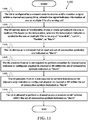
- FIG. 11 is a flow chart 1100 according to one exemplary embodiment from the perspective of a UE (User Equipment).
- the UE is configured by a network node to receive and/or monitor a signal within a channel occupancy time, wherein the signal indicates information of one or multiple TTIs of a serving cell.
- the UE derives state or functionality of one or more symbol(s) in the one or multiple TTIs based on the information, wherein the information indicates a symbol in the one or multiple TTIs to be any of "downlink", “uplink”, “flexible”, or “blank”.
- the UE derives or is indicated that at least one set of consecutive symbol(s) are indicated as "blank”.
- step 1120 the UE prevents from or is not required to perform reception for (dynamically) indicated or configured physical DL channel or RS within the set of consecutive symbols indicated as "blank”.
- step 1125 the UE prevents from or is not required to perform transmission for (dynamically) indicated or configured physical UL channel or RS within the set of consecutive symbols indicated as "blank”.
- step 1130 the UE is allowed to perform a channel access procedure or LBT scheme within the set of consecutive symbols indicated as "blank .
- a (dynamically) indicated physical channel or RS could be indicated by a PDCCH/DCI or MAC-CE.
- the UE could consider or interpret a TTI, among the one or multiple TTIs, as an ending TTI of the channel occupancy time, wherein the TTI comprises the last set of consecutive symbols indicated as "blank and at least one symbol not indicated as "blank”.
- the UE could also consider or interpret a symbol, among the one or more symbol(s), as an ending symbol of the channel occupancy time, wherein the symbol is the last symbol not indicated as "blank” in the ending TTI.
- the UE could prevent from performing (dynamically) indicated or configured physical DL channel or RS reception or (dynamically) indicated or configured physical UL (Uplink) channel or RS transmission, after (the ending symbol within) the ending TTI in the serving cell.
- the information could be or comprise a first slot format combination intended for the channel occupancy time in the serving cell, and/or the signal could be a slot format related DCI.
- the serving cell could be operated operated or located in unlicensed spectrum, and/or a TTI could be replaced with or referred to as a slot.
- the network node could prevent from indicating a symbol in licensed spectrum to be "blank" in a second slot format combination.
- the UE could prevent from performing (i) (dynamically) indicated or configured physical DL channel or RS reception, or (ii) (dynamically) indicated or configured physical UL channel or RS transmission after (the ending symbol within) the ending TTI in the serving cell, until next channel occupancy time starts.
- "Blank” could be replaced with or referred to as "reserved", "empty", "unoccupied”, or "out of channel occupancy time”.
- the first slot format combination and the second slot format combination could be a same slot format combination.
- the reception for (dynamically) indicated or configured physical DL channel or RS may not mean or comprise the monitoring or reception for indication of start of next channel occupancy time.
- the device 300 includes a program code 312 stored in the memory 310.
- the CPU 308 could execute program code 312 to enable the UE (i) to be configured by a network node to receive and/or monitor a signal within a channel occupancy time, wherein the signal indicates information of one or multiple TTIs of a serving cell, (ii) to derive state or functionality of one or more symbol(s) in the one or multiple TTIs based on the information, wherein the information indicates a symbol in the one or multiple TTIs to be any of "downlink", “uplink”, “flexible”, or “blank”, (iii) to derive or be indicated that at least one set of consecutive symbol(s) are indicated as "blank”, (iv) to prevent from or is not required to perform reception for (dynamically) indicated or configured physical DL (Downlink) channel or RS (Reference Signal) within the set of consecutive symbols indicated as "blank”, (
- FIG. 12 is a flow chart 1200 according to one exemplary embodiment from the perspective of a UE.
- the UE is configured by a network node to receive and/or monitor a signal within a channel occupancy time, wherein the signal indicates information of one or multiple TTIs of a serving cell.
- the UE derives state or functionality of one or more symbol(s) in the one or multiple TTIs based on the information, wherein the information indicates a symbol in the one or multiple TTIs to be any of "downlink", “uplink”, “flexible”, or "blank”.
- the UE considers or interprets a TTI, among the one or multiple TTIs, as an ending TTI of the channel occupancy time, wherein the TTI comprises (the last set of) consecutive symbols indicated as "blank” and at least one symbol not indicated as "blank” before the (last set of) consecutive symbols indicated as “blank”.
- the UE considers or interprets a symbol, among the one or more symbol(s), as an ending symbol of the channel occupancy time, wherein the symbol is the last symbol not indicated as "blank” in the ending TTI.
- the UE could prevent from performing (i) (dynamically) indicated or configured physical DL (Downlink) channel or RS reception, or (ii) (dynamically) indicated or configured physical UL (Uplink) channel or RS transmission after (the ending symbol within) the ending TTI in the serving cell, until next channel occupancy time starts.
- the reception for (dynamically) indicated or configured physical DL channel or RS could not mean or comprise the monitoring or reception for indicating start of a or next channel occupancy time.
- the serving cell could be operated or located in unlicensed spectrum, and a TTI could be replaced with or referred to as a slot.
- the device 300 includes a program code 312 stored in the memory 310.
- the CPU 308 could execute program code 312 to enable the UE (i) to be configured by a network node to receive and/or monitor a signal within a channel occupancy time, wherein the signal indicates information of one or multiple TTIs of a serving cell, (ii) to derive state or functionality of one or more symbol(s) in the one or multiple TTIs based on the information, wherein the information indicates a symbol in the one or multiple TTIs to be any of "downlink", "uplink”, “flexible”, or “blank”, (iii) to consider or interpret a TTI, among the one or multiple TTIs, as an ending TTI of the channel occupancy time, wherein the TTI comprises (the last set of) consecutive symbols indicated as "blank " and at least one symbol not indicated as "blank” before the (last set of) consecutive symbols indicated as "blank
- FIG. 13 is a flow chart 1300 according to one exemplary embodiment from the perspective of a UE.
- the UE is configured by a network node to receive and/or monitor an indication in or for a serving cell.
- the UE derives (information of) an ending TTI of a channel occupancy time at least based on the indication.
- the UE derives (information of) a first symbol at least based on the indication, wherein the first symbol is within the ending TTI and considered or determined as an ending symbol of the channel occupancy time.
- the UE receives a DCI (Downlink Control Information) scheduling a resource for a transmission or reception in the serving cell, wherein a second symbol is the last symbol of the scheduled resource.
- DCI Downlink Control Information
- step 1325 if the second symbol is later than or located after the first symbol, the UE (re-) considers or (re-) determines the second symbol is the ending symbol of the channel occupancy time. In step 1330, the UE performs the transmission or reception on the scheduled resource until (the end of) the ending symbol or the second symbol.
- the second symbol could overwrite the first symbol (to be considered or determined) as the ending symbol of the channel occupancy time, if the second symbol is later than or located after the first symbol.
- the UE could receive the indication within the channel occupancy time.
- the indication could be or comprise a slot formation indicator or a slot format combination or a slot format value.
- the UE could consider the DCI as valid, and/or the UE may not neglect or may not ignore the DCI, even though the last symbol of the scheduled resource in the DCI is later than or located after the first symbol.
- the UE could prevent from performing (i) (dynamically) indicated or configured physical DL (Downlink) channel or RS (Reference Signal) reception, or (ii) (dynamically) indicated or configured physical UL (Uplink) channel or RS (Reference Signal) transmission, after (the ending symbol within) the ending TTI in the serving cell, until next channel occupancy time starts.
- the information of an ending TTI may comprise at least one of the following: (index of) an ending TTI, and state or transmission direction or functionality of one or more symbols within an ending TTI.
- the information of a first symbol may comprise at least one of the following: (index of) an ending or first symbol, and state or transmission direction or functionality of an ending or first symbol.
- the UE could prevent from performing (dynamically) indicated or configured physical DL channel or RS reception, or (dynamically) indicated or configured physical UL channel or RS transmission, after the first symbol, until next channel occupancy time starts.
- the first symbol could be the last symbol not indicated as "flexible" in the ending TTI.
- the serving cell could be operated or located in unlicensed spectrum, and/or a TTI could be replaced with or referred to as a slot.
- the reception for (dynamically) indicated or configured physical DL (Downlink) channel or RS (Reference Signal) may not mean or comprise the monitoring or reception for indicating start of a or next channel occupancy time.
- the device 300 includes a program code 312 stored in the memory 310.
- the CPU 308 could execute program code 312 to enable the UE (i) to be configured by a network node to receive and/or monitor an indication in or for a serving cell, (ii) to derive (information of) an ending TTI of a channel occupancy time at least based on the indication, (iii) to derives (information of) a first symbol at least based on the indication, wherein the first symbol is within the ending TTI and considered or determined as an ending symbol of the channel occupancy time, (iv) to receive a DCI scheduling a resource for transmission or reception in the serving cell, wherein a second symbol is the last symbol of the scheduled resource, (v) to (re-) consider or (re-) determine the second symbol is the ending symbol of the channel occupancy time if the second symbol is later than or located after the first symbol, and (vi) to perform the transmission or reception on the scheduled resource
- concurrent channels could be established based on pulse repetition frequencies.
- concurrent channels could be established based on pulse position or offsets.
- concurrent channels could be established based on time hopping sequences.
- concurrent channels could be established based on pulse repetition frequencies, pulse positions or offsets, and time hopping sequences.
- the various illustrative logical blocks, modules, and circuits described in connection with the aspects disclosed herein may be implemented within or performed by an integrated circuit ("IC"), an access terminal, or an access point.
- the IC may comprise a general purpose processor, a digital signal processor (DSP), an application specific integrated circuit (ASIC), a field programmable gate array (FPGA) or other programmable logic device, discrete gate or transistor logic, discrete hardware components, electrical components, optical components, mechanical components, or any combination thereof designed to perform the functions described herein, and may execute codes or instructions that reside within the IC, outside of the IC, or both.
- a general purpose processor may be a microprocessor, but in the alternative, the processor may be any conventional processor, controller, microcontroller, or state machine.
- a processor may also be implemented as a combination of computing devices, e.g., a combination of a DSP and a microprocessor, a plurality of microprocessors, one or more microprocessors in conjunction with a DSP core, or any other such configuration.
- a software module e.g., including executable instructions and related data
- other data may reside in a data memory such as RAM memory, flash memory, ROM memory, EPROM memory, EEPROM memory, registers, a hard disk, a removable disk, a CD-ROM, or any other form of computer-readable storage medium known in the art.
- a sample storage medium may be coupled to a machine such as, for example, a computer/processor (which may be referred to herein, for convenience, as a "processor") such the processor can read information (e.g., code) from and write information to the storage medium.
- a sample storage medium may be integral to the processor.
- the processor and the storage medium may reside in an ASIC.
- the ASIC may reside in user equipment.
- the processor and the storage medium may reside as discrete components in user equipment.
- any suitable computer-program product may comprise a computer-readable medium comprising codes relating to one or more of the aspects of the disclosure.
- a computer program product may comprise packaging materials.
Landscapes
- Engineering & Computer Science (AREA)
- Signal Processing (AREA)
- Computer Networks & Wireless Communication (AREA)
- Mobile Radio Communication Systems (AREA)
Applications Claiming Priority (1)
| Application Number | Priority Date | Filing Date | Title |
|---|---|---|---|
| US201862717445P | 2018-08-10 | 2018-08-10 |
Publications (2)
| Publication Number | Publication Date |
|---|---|
| EP3609283A2 true EP3609283A2 (fr) | 2020-02-12 |
| EP3609283A3 EP3609283A3 (fr) | 2020-05-27 |
Family
ID=67658626
Family Applications (1)
| Application Number | Title | Priority Date | Filing Date |
|---|---|---|---|
| EP19190954.8A Withdrawn EP3609283A3 (fr) | 2018-08-10 | 2019-08-09 | Procédé et appareil d'indication de format de créneau pour un créneau final dans un spectre sans licence dans un système de communication sans fil |
Country Status (4)
| Country | Link |
|---|---|
| US (1) | US20200052865A1 (fr) |
| EP (1) | EP3609283A3 (fr) |
| KR (1) | KR102263787B1 (fr) |
| CN (1) | CN110831201A (fr) |
Families Citing this family (36)
| Publication number | Priority date | Publication date | Assignee | Title |
|---|---|---|---|---|
| EP4475622A3 (fr) | 2014-09-24 | 2025-03-12 | InterDigital Patent Holdings, Inc. | Indication d'utilisation de canal et synchronisation pour fonctionnement lte dans des bandes sans licence |
| WO2019027297A1 (fr) * | 2017-08-04 | 2019-02-07 | 엘지전자 주식회사 | Procédé par lequel un terminal transmet un signal de liaison montante dans un système de communication sans fil prenant en charge une bande sans licence, et appareil de prise en charge de celui-ci |
| KR20250174992A (ko) * | 2018-05-10 | 2025-12-15 | 인터디지탈 패튼 홀딩스, 인크 | 스펙트럼 재이용, 전력 절감 및 공존을 위한 채널 액세스 표시 |
| US10945264B2 (en) * | 2018-08-10 | 2021-03-09 | Asustek Computer Inc. | Method and apparatus for applying slot format indication (SFI) to a cell in unlicensed spectrum in a wireless communication system |
| KR20250139890A (ko) * | 2018-08-20 | 2025-09-23 | 주식회사 윌러스표준기술연구소 | 무선 통신 시스템의 물리 제어 채널 수신 방법 및 이를 이용하는 장치 |
| US11089585B2 (en) | 2018-09-14 | 2021-08-10 | Ofinno, Llc | Transmission structure and access for a radio system |
| US11083018B2 (en) * | 2018-09-17 | 2021-08-03 | Ofinno, Llc | Transmission structure with beamforming for a radio system |
| WO2020112861A1 (fr) * | 2018-11-28 | 2020-06-04 | Qualcomm Incorporated | Mappage de ressources de fréquence pour canal physique de contrôle de liaison montante/accusé de réception (pucch/ack) et liaison montante autonome (aul) dans une nouvelle radio sans licence (nr-u) |
| US20220167383A1 (en) * | 2019-03-25 | 2022-05-26 | Sharp Kabushiki Kaisha | User equipments, base stations and methods for processing of priority indication |
| MX2021011786A (es) * | 2019-03-28 | 2021-10-26 | Sharp Kk | Gestion de recursos para redes de retorno inalambricas. |
| WO2020228954A1 (fr) * | 2019-05-16 | 2020-11-19 | Telefonaktiebolaget Lm Ericsson (Publ) | Transmission formée en faisceau vers des groupes de dispositifs terminaux |
| US11432325B2 (en) * | 2019-07-11 | 2022-08-30 | Qualcomm Incorporated | Methods, apparatuses and systems for user equipment (UE)-to-UE sharing of channel occupancy time |
| BR112022005227A2 (pt) * | 2019-10-07 | 2022-06-14 | Ericsson Telefon Ab L M | Métodos realizados por um dispositivo de comunicação sem fio e por um nó de rede, dispositivo de comunicação sem fio, e, nó de rede |
| US11497027B2 (en) * | 2020-01-21 | 2022-11-08 | Qualcomm Incorporated | Half duplex FDD user equipment operation |
| FR3107413B1 (fr) * | 2020-02-17 | 2022-01-28 | Commissariat Energie Atomique | Méthode d’allocation de ressources pour système de communication à étalement de spectre |
| TWI770884B (zh) * | 2020-03-27 | 2022-07-11 | 聯發科技股份有限公司 | 支援5g新無線電未授權頻譜中基於參考訊號的測量的ue能力信令 |
| CN113472494B (zh) * | 2020-03-31 | 2023-10-13 | 北京紫光展锐通信技术有限公司 | 上行传输的信道接入方法及装置、存储介质、终端 |
| BR112022020191A2 (pt) * | 2020-04-10 | 2022-11-22 | Nokia Technologies Oy | Ajuste para avanço de tempo |
| CN115380488B (zh) * | 2020-04-16 | 2023-07-04 | 高通股份有限公司 | 用于侧行链路通信的信道占用时间(cot)共享时的循环前缀(cp)扩展 |
| US11617199B2 (en) * | 2020-06-23 | 2023-03-28 | Asustek Computer Inc. | Method and apparatus of indicating time delay in a wireless communication system |
| US12477577B2 (en) | 2020-07-13 | 2025-11-18 | Nokia Technologies Oy | Channel sensing |
| US20230262691A1 (en) * | 2020-08-13 | 2023-08-17 | Beijing Xiaomi Mobile Software Co., Ltd. | Uplink transmission sending method and apparatus, uplink transmission receiving method and apparatus, communication device, and medium |
| US12193015B2 (en) * | 2020-09-28 | 2025-01-07 | Qualcomm Incorporated | Control channel designs for dynamic full duplex enabling |
| EP4223066A4 (fr) * | 2020-09-30 | 2024-11-06 | Sharp Kabushiki Kaisha | Équipements utilisateurs, stations de base et procédés |
| KR102781826B1 (ko) * | 2020-10-08 | 2025-03-18 | 엘지전자 주식회사 | 무선 통신 시스템에서 신호를 송수신하는 방법 및 장치 |
| US11930532B2 (en) * | 2020-10-16 | 2024-03-12 | Samsung Electronics Co., Ltd | Beam management and beam failure recovery in new radio-unlicensed at 60 Gigahertz |
| CN116368842B (zh) * | 2020-10-16 | 2025-08-26 | 苹果公司 | 高毫米波系统中的波束形成故障检测和恢复 |
| WO2022153463A1 (fr) * | 2021-01-14 | 2022-07-21 | 株式会社Nttドコモ | Station de base et procédé de communication |
| US20220231801A1 (en) * | 2021-01-15 | 2022-07-21 | Mediatek Inc. | Apparatus and method for configuring application of tci state to component carriers |
| US20240172199A1 (en) * | 2021-03-04 | 2024-05-23 | Lenovo (Singapore) Pte. Ltd. | Indication of uplink transmission in downlink symbol |
| WO2022213328A1 (fr) * | 2021-04-08 | 2022-10-13 | 华为技术有限公司 | Procédé de configuration de ressources de liaison latérale et appareil de communication |
| US11889537B2 (en) * | 2021-05-01 | 2024-01-30 | Qualcomm Incorporated | Rules for updating slot format supporting full duplex operation |
| US20240381412A1 (en) * | 2021-09-27 | 2024-11-14 | Beijing Xiaomi Mobile Software Co., Ltd. | Method and apparatus for receiving and sending physical downlink shared channel, and medium |
| CN116112138B (zh) * | 2021-11-10 | 2025-04-15 | 华硕电脑股份有限公司 | 无线通信系统中用于传送方向指示的方法和设备 |
| CN119814254A (zh) * | 2024-06-07 | 2025-04-11 | 荣耀终端股份有限公司 | 一种用于无线通信的节点中的与pucch有关的方法和装置 |
| CN121126536A (zh) * | 2024-06-11 | 2025-12-12 | 华为技术有限公司 | 通信方法及相关装置 |
Family Cites Families (7)
| Publication number | Priority date | Publication date | Assignee | Title |
|---|---|---|---|---|
| US10637619B2 (en) * | 2014-11-03 | 2020-04-28 | Samsung Electronics Co., Ltd. | Method and apparatus for channel access for LTE on unlicensed spectrum |
| US11006400B2 (en) * | 2015-01-16 | 2021-05-11 | Sharp Kabushiki Kaisha | User equipments, base stations and methods |
| US10009153B2 (en) * | 2015-01-30 | 2018-06-26 | Motorola Mobility Llc | Apparatus and method for reception and transmission of control channels |
| US9930654B2 (en) * | 2015-03-17 | 2018-03-27 | Motorola Mobility Llc | Method and apparatus for scheduling user equipment uplink transmissions on an unlicensed carrier |
| JP2018520601A (ja) * | 2015-07-10 | 2018-07-26 | エルジー エレクトロニクス インコーポレイティド | 非免許帯域を支援する無線接続システムにおいてディスカバリ参照信号を送信する方法及び装置 |
| US11304226B2 (en) * | 2016-05-09 | 2022-04-12 | Sharp Kabushiki Kaisha | User equipments, base stations and methods |
| US20170332395A1 (en) * | 2016-05-11 | 2017-11-16 | Sharp Laboratories Of America, Inc. | Systems and methods for physical uplink shared channel (pusch) format signaling and contention access |
-
2019
- 2019-08-09 CN CN201910735100.1A patent/CN110831201A/zh not_active Withdrawn
- 2019-08-09 EP EP19190954.8A patent/EP3609283A3/fr not_active Withdrawn
- 2019-08-09 US US16/536,794 patent/US20200052865A1/en not_active Abandoned
- 2019-08-09 KR KR1020190097576A patent/KR102263787B1/ko not_active Expired - Fee Related
Non-Patent Citations (7)
| Title |
|---|
| "Multiplexing and channel coding", TS 38.212 |
| "Physical channels and modulation", TS 38.211 |
| "Physical layer procedures for control", TS 38.213 |
| "Physical layer procedures for shared spectrum channel access", TS 37.213 |
| "Radio Resource Control (RRC) protocol specification", TS 38.331 |
| DRAFT REPORT OF 3GPP TSG RAN WG1 #93, 21 May 2018 (2018-05-21) |
| FINAL REPORT OF 3GPP TSG RAN WG1 #92BIS, 16 April 2018 (2018-04-16) |
Also Published As
| Publication number | Publication date |
|---|---|
| US20200052865A1 (en) | 2020-02-13 |
| KR20200018349A (ko) | 2020-02-19 |
| KR102263787B1 (ko) | 2021-06-11 |
| CN110831201A (zh) | 2020-02-21 |
| EP3609283A3 (fr) | 2020-05-27 |
Similar Documents
| Publication | Publication Date | Title |
|---|---|---|
| US20200052865A1 (en) | Method and apparatus for slot format indication for an ending slot in unlicensed spectrum in a wireless communication system | |
| US11533720B2 (en) | Method and apparatus for applying slot format indication (SFI) to a cell in unlicensed spectrum in a wireless communication system | |
| US11553485B2 (en) | Method and apparatus for indicating slot format of an unlicensed cell in a wireless communication system | |
| EP3599733B1 (fr) | Procédé et appareil pour procédé d'économie d'énergie sur une réception de canal physique partagé descendante (ppdsch) dans un système de communication sans fil | |
| EP3609097B1 (fr) | Procédé et appareil permettant d'estimer la perte de trajet de pusch dans un système de communication sans fil | |
| EP3525542B1 (fr) | Procédé et appareil de surveillance d'une indication de transmission interrompue dans un système de communication sans fil | |
| EP3445123B1 (fr) | Procédé et appareil de configuration d'accès aléatoire dans un système de communication sans fil | |
| US10701734B2 (en) | Method and apparatus of selecting bandwidth part for random access (RA) procedure in a wireless communication system | |
| US11546121B2 (en) | Operation method of terminal and base station in wireless communication system supporting unlicensed band and device for supporting same | |
| EP3547593A1 (fr) | Procédé et appareil pour déterminer la taille d'un livre de codes dans un système de communication sans fil | |
| US12574966B2 (en) | Method and apparatus for listen-before-talk mode for random access response in a wireless communication system | |
| EP4012968B1 (fr) | Procédé et appareil d'indication de numéro d'agrégation dans un système de communication sans fil | |
| EP4033849A1 (fr) | Procédé et appareil permettant de déterminer l'accès de canal dans un système de communication sans fil | |
| CN116867099A (zh) | 在非授权带中发送物理信道的方法、装置和系统 | |
| US20230145355A1 (en) | Method and apparatus for transmission direction indication in a wireless communication system | |
| CN114828242B (zh) | 无线通信系统中用于信道接入切换的方法和设备 | |
| EP4181607A1 (fr) | Procédé et appareil d'indication de format de créneau dans un système de communication sans fil | |
| KR20250049191A (ko) | 무선 통신 시스템에서 감소된 기능성을 갖는 송신 및 수신 포인트로의 업링크 송신을 위한 방법 및 장치 |
Legal Events
| Date | Code | Title | Description |
|---|---|---|---|
| PUAI | Public reference made under article 153(3) epc to a published international application that has entered the european phase |
Free format text: ORIGINAL CODE: 0009012 |
|
| STAA | Information on the status of an ep patent application or granted ep patent |
Free format text: STATUS: THE APPLICATION HAS BEEN PUBLISHED |
|
| AK | Designated contracting states |
Kind code of ref document: A2 Designated state(s): AL AT BE BG CH CY CZ DE DK EE ES FI FR GB GR HR HU IE IS IT LI LT LU LV MC MK MT NL NO PL PT RO RS SE SI SK SM TR |
|
| AX | Request for extension of the european patent |
Extension state: BA ME |
|
| PUAL | Search report despatched |
Free format text: ORIGINAL CODE: 0009013 |
|
| AK | Designated contracting states |
Kind code of ref document: A3 Designated state(s): AL AT BE BG CH CY CZ DE DK EE ES FI FR GB GR HR HU IE IS IT LI LT LU LV MC MK MT NL NO PL PT RO RS SE SI SK SM TR |
|
| AX | Request for extension of the european patent |
Extension state: BA ME |
|
| RIC1 | Information provided on ipc code assigned before grant |
Ipc: H04W 74/08 20090101AFI20200420BHEP Ipc: H04L 5/00 20060101ALI20200420BHEP Ipc: H04W 72/04 20090101ALN20200420BHEP |
|
| STAA | Information on the status of an ep patent application or granted ep patent |
Free format text: STATUS: REQUEST FOR EXAMINATION WAS MADE |
|
| 17P | Request for examination filed |
Effective date: 20200818 |
|
| RBV | Designated contracting states (corrected) |
Designated state(s): AL AT BE BG CH CY CZ DE DK EE ES FI FR GB GR HR HU IE IS IT LI LT LU LV MC MK MT NL NO PL PT RO RS SE SI SK SM TR |
|
| STAA | Information on the status of an ep patent application or granted ep patent |
Free format text: STATUS: EXAMINATION IS IN PROGRESS |
|
| 17Q | First examination report despatched |
Effective date: 20211220 |
|
| STAA | Information on the status of an ep patent application or granted ep patent |
Free format text: STATUS: THE APPLICATION IS DEEMED TO BE WITHDRAWN |
|
| 18D | Application deemed to be withdrawn |
Effective date: 20230728 |