EP3609736B1 - Siège absorbant les chocs avec éléments d'amortissement - Google Patents
Siège absorbant les chocs avec éléments d'amortissement Download PDFInfo
- Publication number
- EP3609736B1 EP3609736B1 EP18717621.9A EP18717621A EP3609736B1 EP 3609736 B1 EP3609736 B1 EP 3609736B1 EP 18717621 A EP18717621 A EP 18717621A EP 3609736 B1 EP3609736 B1 EP 3609736B1
- Authority
- EP
- European Patent Office
- Prior art keywords
- seat
- belt
- damping element
- shaped
- damping
- Prior art date
- Legal status (The legal status is an assumption and is not a legal conclusion. Google has not performed a legal analysis and makes no representation as to the accuracy of the status listed.)
- Active
Links
Images


Classifications
-
- B—PERFORMING OPERATIONS; TRANSPORTING
- B60—VEHICLES IN GENERAL
- B60N—SEATS SPECIALLY ADAPTED FOR VEHICLES; VEHICLE PASSENGER ACCOMMODATION NOT OTHERWISE PROVIDED FOR
- B60N2/00—Seats specially adapted for vehicles; Arrangement or mounting of seats in vehicles
- B60N2/24—Seats specially adapted for vehicles; Arrangement or mounting of seats in vehicles for particular purposes or particular vehicles
-
- B—PERFORMING OPERATIONS; TRANSPORTING
- B60—VEHICLES IN GENERAL
- B60N—SEATS SPECIALLY ADAPTED FOR VEHICLES; VEHICLE PASSENGER ACCOMMODATION NOT OTHERWISE PROVIDED FOR
- B60N2/00—Seats specially adapted for vehicles; Arrangement or mounting of seats in vehicles
- B60N2/24—Seats specially adapted for vehicles; Arrangement or mounting of seats in vehicles for particular purposes or particular vehicles
- B60N2/42—Seats specially adapted for vehicles; Arrangement or mounting of seats in vehicles for particular purposes or particular vehicles the seat constructed to protect the occupant from the effect of abnormal g-forces, e.g. crash or safety seats
- B60N2/4207—Seats specially adapted for vehicles; Arrangement or mounting of seats in vehicles for particular purposes or particular vehicles the seat constructed to protect the occupant from the effect of abnormal g-forces, e.g. crash or safety seats characterised by the direction of the g-forces
- B60N2/4235—Seats specially adapted for vehicles; Arrangement or mounting of seats in vehicles for particular purposes or particular vehicles the seat constructed to protect the occupant from the effect of abnormal g-forces, e.g. crash or safety seats characterised by the direction of the g-forces transversal
-
- B—PERFORMING OPERATIONS; TRANSPORTING
- B60—VEHICLES IN GENERAL
- B60N—SEATS SPECIALLY ADAPTED FOR VEHICLES; VEHICLE PASSENGER ACCOMMODATION NOT OTHERWISE PROVIDED FOR
- B60N2/00—Seats specially adapted for vehicles; Arrangement or mounting of seats in vehicles
- B60N2/24—Seats specially adapted for vehicles; Arrangement or mounting of seats in vehicles for particular purposes or particular vehicles
- B60N2/42—Seats specially adapted for vehicles; Arrangement or mounting of seats in vehicles for particular purposes or particular vehicles the seat constructed to protect the occupant from the effect of abnormal g-forces, e.g. crash or safety seats
- B60N2/4207—Seats specially adapted for vehicles; Arrangement or mounting of seats in vehicles for particular purposes or particular vehicles the seat constructed to protect the occupant from the effect of abnormal g-forces, e.g. crash or safety seats characterised by the direction of the g-forces
- B60N2/4242—Seats specially adapted for vehicles; Arrangement or mounting of seats in vehicles for particular purposes or particular vehicles the seat constructed to protect the occupant from the effect of abnormal g-forces, e.g. crash or safety seats characterised by the direction of the g-forces vertical
-
- B—PERFORMING OPERATIONS; TRANSPORTING
- B60—VEHICLES IN GENERAL
- B60N—SEATS SPECIALLY ADAPTED FOR VEHICLES; VEHICLE PASSENGER ACCOMMODATION NOT OTHERWISE PROVIDED FOR
- B60N2/00—Seats specially adapted for vehicles; Arrangement or mounting of seats in vehicles
- B60N2/24—Seats specially adapted for vehicles; Arrangement or mounting of seats in vehicles for particular purposes or particular vehicles
- B60N2/42—Seats specially adapted for vehicles; Arrangement or mounting of seats in vehicles for particular purposes or particular vehicles the seat constructed to protect the occupant from the effect of abnormal g-forces, e.g. crash or safety seats
- B60N2/427—Seats or parts thereof displaced during a crash
- B60N2/42709—Seats or parts thereof displaced during a crash involving residual deformation or fracture of the structure
-
- B—PERFORMING OPERATIONS; TRANSPORTING
- B60—VEHICLES IN GENERAL
- B60R—VEHICLES, VEHICLE FITTINGS, OR VEHICLE PARTS, NOT OTHERWISE PROVIDED FOR
- B60R22/00—Safety belts or body harnesses in vehicles
- B60R22/12—Construction of belts or harnesses
-
- B—PERFORMING OPERATIONS; TRANSPORTING
- B60—VEHICLES IN GENERAL
- B60R—VEHICLES, VEHICLE FITTINGS, OR VEHICLE PARTS, NOT OTHERWISE PROVIDED FOR
- B60R22/00—Safety belts or body harnesses in vehicles
- B60R22/28—Safety belts or body harnesses in vehicles incorporating energy-absorbing devices
-
- F—MECHANICAL ENGINEERING; LIGHTING; HEATING; WEAPONS; BLASTING
- F41—WEAPONS
- F41H—ARMOUR; ARMOURED TURRETS; ARMOURED OR ARMED VEHICLES; MEANS OF ATTACK OR DEFENCE, e.g. CAMOUFLAGE, IN GENERAL
- F41H7/00—Armoured or armed vehicles
- F41H7/02—Land vehicles with enclosing armour, e.g. tanks
- F41H7/04—Armour construction
- F41H7/046—Shock resilient mounted seats for armoured or fighting vehicles
-
- B—PERFORMING OPERATIONS; TRANSPORTING
- B60—VEHICLES IN GENERAL
- B60R—VEHICLES, VEHICLE FITTINGS, OR VEHICLE PARTS, NOT OTHERWISE PROVIDED FOR
- B60R22/00—Safety belts or body harnesses in vehicles
- B60R22/02—Semi-passive restraint systems, e.g. systems applied or removed automatically but not both ; Manual restraint systems
- B60R2022/027—Four-point seat belt systems, e.g. with the two upper points connected together
-
- B—PERFORMING OPERATIONS; TRANSPORTING
- B60—VEHICLES IN GENERAL
- B60R—VEHICLES, VEHICLE FITTINGS, OR VEHICLE PARTS, NOT OTHERWISE PROVIDED FOR
- B60R22/00—Safety belts or body harnesses in vehicles
- B60R22/28—Safety belts or body harnesses in vehicles incorporating energy-absorbing devices
- B60R2022/283—Safety belts or body harnesses in vehicles incorporating energy-absorbing devices using tearing or scoring of material
-
- B—PERFORMING OPERATIONS; TRANSPORTING
- B60—VEHICLES IN GENERAL
- B60R—VEHICLES, VEHICLE FITTINGS, OR VEHICLE PARTS, NOT OTHERWISE PROVIDED FOR
- B60R22/00—Safety belts or body harnesses in vehicles
- B60R22/28—Safety belts or body harnesses in vehicles incorporating energy-absorbing devices
- B60R2022/286—Safety belts or body harnesses in vehicles incorporating energy-absorbing devices using deformation of material
Definitions
- the invention relates to a seat for a land vehicle which is equipped with at least one damping element.
- a deformation element for protecting a device, in particular a footrest plate in a particularly military vehicle, is known, wherein the deformation element is essentially U-shaped.
- the US 2013/0033056 A1 discloses a cushioning system with belts for a suspended seat. Belts are disclosed which have zones that guide the belt in multiple layers and are held in place by seams. When force is applied, these seams can then tear to compensate for the force.
- the DE 10 2010 020533 A1 discloses a shock-absorbing structural bearing comprising one or more rod-shaped crash elements.
- the rod-shaped crash element(s) each have a predetermined breaking point bridged by at least two tabs.
- the invention is based on the object of providing a seat for a vehicle with which the person is protected from external impacts.
- the seat according to the invention comprises the technical features defined in claim 1.
- an attenuation element which has two points of application in order to introduce pulse-like forces into the attenuation element.
- the damping element also has fastening elements, by means of which the damping element can be fastened.
- the fastening points are preferably arranged at the points of application, so that the force can be applied to the damping element through the fastening elements.
- the fastening elements are designed as tubes. These can then be inserted into existing tubes of a seat and/or the chassis of a vehicle. To fix the pipes, it is then proposed to provide holes in the pipes, which are fixed using screw or plug connections.
- Such a fixation or design as a plug-in pipe system has the advantage of being quick to replace. Accordingly, the damping elements can also be used as spare parts.
- the damping element also has an absorption medium which is able to absorb introduced forces and thus dampen the impulsive force effects.
- Such an absorbent can be a compressible material or an elastic material which returns to its original position after the application of force.
- an additional absorption medium is provided which can also absorb forces and thus contributes to the damping. The damping then occurs through the interaction of the absorption medium and the additional absorption medium.
- the additional absorption medium absorbs the forces acting on it through deformation work. This means that the additional absorption medium is deformed when the force is applied. However, such deformation does not occur under conventional loading and/or force acting on the damping element. Only when a certain force is exceeded is this converted into deformation work. This means that the shape is retained under normal loading of the damping element.
- the damping element has a housing, which can have various shapes. It is proposed to arrange the absorption means inside the housing. The additional absorption means can then be the housing or a part of the housing.
- the parts of the housing intended for deformation are provided with round shapes.
- a heart or cloverleaf shape is therefore preferably proposed for the housing, as these shapes have proven to be particularly suitable for such deformation.
- the damping element is designed as a belt. Due to its physical properties, the belt acts as a Absorbent.
- the belt is preferably provided with elasticity and is made of multiple layers, at least in some areas.
- the additional absorbent consists of seams that connect at least two layers of the belt together.
- the possible deformation work of the additional absorbent takes place by separating the seams when force is applied.
- the seams of the belt are preferably arranged parallel to each other and running across the belt. This creates a number of seams that run parallel to each other and at a distance from each other across the belt. The distances can be the same or different for all seams. These seams are provided at least in some areas on a belt.
- Such a belt can be hinged with its attachment points to a seat and/or the chassis.
- the belt can be arranged in such a way that a person on the seat is protected or movable parts of the seat are dampened.
- the belt can be hinged to the seat and backrest of the seat in order to dampen a foldable seat. If a force is applied from below, for example, the force then acts on the seat. If the seat has a movable or foldable seat, the inertia of the person on the seat can dampen an upward movement of the seat if a damping element is designed as a belt and is hinged to the seat and the seat back. Hinge to the seat and chassis is also conceivable for this purpose.
- the points of application be offset from one another so that they are not aligned. This has the advantage that when force is applied to the points of application, the fastening elements can move in the direction of the damping element without hindering one another.
- the damping elements are designed in such a way that they can be used in a vehicle to cushion a vehicle seat against impact forces acting on the seat. To this end, it is proposed to arrange at least one damping element on the vehicle seat. The movement of a person sitting in the seat can also be dampened by the damping elements.
- the seat can be dampened by arranging at least one damping element between the seat and the vehicle chassis.
- the seat can also be equipped with appropriate belts. A combination of the above arrangements is also conceivable.
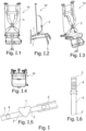
- a damping element 1 which has a housing and is approximately heart-shaped when viewed from the side.
- a fastening element 3 is arranged on each side of the heart-shaped damping element 1 at the points of application 2.
- the fastening element 3 is preferably tubular.
- the longitudinal axes of the two tubes are offset in height from one another.
- the cross-sectionally heart-shaped damping element 1 is formed by a sheet metal surrounding the narrower outer sides, to which the tubes arranged, in particular welded on.
- the interior of the heart-shaped damping element 1 is filled with an elastically deformable material which represents the absorption medium.
- the two tube ends that protrude from the heart-shaped damping element 1 connect the seat 10 to its chassis and to a chassis 11 of the vehicle.
- the tubes can also be inserted into existing tubes of the seat and/or the chassis to create a plug connection.
- holes 6 provided for this purpose in the tubes enable the plug connection to be fixed. Such a connection is possible, for example, in Figure I.5 shown.
- the heart-shaped damping element 1 enables the impact energy to be absorbed both by the deformation of the outer heart-shaped
- Deformation is achieved by the fact that the two longitudinal axes of the two fastening tubes are not aligned but are offset in height from one another. This allows the heart-shaped damping element 1 to be pushed into one another in order to reduce the deformation energy and thus significantly weaken the impact effect from the outside, so that the person sitting on the seat 10 is very well protected from this external influence.
- the damping element 1 is integrated in a belt 5.
- the person sitting on the seat 10 can buckle themselves up using such a belt 5, but belts can also be attached to the seat 10 and/or the chassis of a vehicle in order to dampen moving parts of the seat 10.
- the belt 5 is connected in the usual way on the one hand to the seat 10 and on the other hand to the chassis 11 or again to the seat.
- the fastenings of the belts 5 form the fastening elements 3 of the damping element 1 and the ends of the belt 5 form the points of application 2.
- the several seam lines arranged one behind the other and parallel to each other along the length of the belt 5 create a kind of predetermined breaking point, since the seams tear open one after the other as a result of the impact from the outside and thereby reduce the impact energy.
- these multiple seam lines arranged parallel to one another are dimensioned in such a way that they do not normally tear up to the maximum load that the seat 10 may be subjected to.
- Figure II.7 shows a possible seam arrangement for a damping element 1 as a belt 5.
- the seams running parallel to each other and across the belt 5 connect two layers of the belt 5.
- the belt 5 itself is multi-layered in the area of the seams. This can be done by loops that the belt 5 forms in the area of the seams, but the belt 5 can also form the multi-layered area by overlapping several belt pieces.
- seams When force is applied to the belt at the points of application 2, a shear force acts on the seams, which can then be separated and cause the damping of the damping element 1.
- the seams can connect two layers each, as shown, but they can also be continuous through all layers.
- the different seams can be made of different materials, with different tearing behavior.
- the belt is designed in such a way that the damping element is not activated under normal conditions or when force is applied.
- the damping element only becomes active when a certain load limit is exceeded.
- a seat of a vehicle which is connected to the seat 10 by means of the heart-shaped damping element 1 via pipes or the like arranged thereon.
- the damping element 1 is also connected to a chassis 11 of a vehicle (not shown) via pipes or the like.
- the seat 10 shown is equipped with the damping element 1 integrated in the belt 5.
- the seat 10 is arranged on the rear side via several heart-shaped damping elements 1 on the chassis 11 of the vehicle.
- Figure II also shows that the heart-shaped damping element 1 and the damping element 1 integrated in the belt 5 are used as damping elements 1.
- the seat 10 is arranged and fastened via the heart-shaped damping elements 1 not at the rear, but at the side at a suitable location in the vehicle.
- Figure II.2 shows a particularly preferred arrangement of the damping elements 1 designed as a belt 5.
- the belt 5 is hinged to the seat 10 at each of its points of application 2, with one end of the belt 5 being hinged to the backrest of the seat and the other end of the belt 5 to the seat 10. This allows the seat 10 to be dampened when a force is applied to the vehicle if the seat surface of the seat 10 is designed to be movable, e.g. foldable.
- both types of damping elements 1 are also used, whereby here, not a heart-shaped, but a cloverleaf-shaped damping element 1 is used.
- This at least one cloverleaf-shaped damping element 1 is arranged between a chassis 11 of the vehicle, for example a floor plate, and a chassis of the seat 10, for example an underside of the seat surface.
- a cloverleaf-shaped cross-section can also be considered, as shown in Figure III.
- Such a cloverleaf-shaped cross-section of the damping element 1 is used when it is arranged, for example, between the chassis 11 of the vehicle and the chassis of the seat, so that the fastening tubes required for the heart-shaped damping element 1 can be omitted, but do not have to be. Tubes can also be attached to a cloverleaf-shaped damping element 1 in order to arrange and fasten the damping element 1 at its installation location.
- the additional absorption element can be designed as a cover around the absorption element.
- a housing can then also be arranged around the two damping elements. Plug connections at the points of application and/or fastening elements are also possible in order to enable the damping elements to be easily replaced.
Landscapes
- Engineering & Computer Science (AREA)
- Mechanical Engineering (AREA)
- Aviation & Aerospace Engineering (AREA)
- Transportation (AREA)
- Textile Engineering (AREA)
- General Engineering & Computer Science (AREA)
- Seats For Vehicles (AREA)
- Automotive Seat Belt Assembly (AREA)
- Pharmaceuticals Containing Other Organic And Inorganic Compounds (AREA)
- Plural Heterocyclic Compounds (AREA)
Claims (8)
- Siège (10) pour un véhicule terrestre,- dans lequel le siège (10) comprend au moins un organe d'amortissement (1),- dans lequel l'organe d'amortissement (1) présente au moins deux points d'attaque (2) ainsi que des éléments de fixation (3),- dans lequel l'organe d'amortissement (1) présente un moyen d'absorption,- dans lequel un moyen d'absorption supplémentaire (4) est prévu, lequel conjointement avec le moyen d'absorption, provoque une absorption des chocs,- dans lequel les points d'attaque (2) sont décalés les uns par rapport aux autres, et- dans lequel les points d'attaque (2) sont disposés de telle sorte qu'ils ne sont pas alignés les uns avec les autres,- dans lequel l'organe d'amortissement (1) présente un boîtier, caractérisé en ce que le siège (10) comprend au moins une sangle (5) et l'organe d'amortissement (1) est intégré dans la sangle (5).
- Siège (10) selon la revendication 1, caractérisé en ce que- le moyen d'absorption est disposé à l'intérieur de l'organe d'amortissement (1).
- Siège (10) selon la revendication 1 ou 2, caractérisé en ce- le moyen d'absorption supplémentaire (4) est constitué de parties déformables du boîtier.
- Siège (10) selon l'une quelconque des revendications 1 à 3, caractérisé en ce que- les éléments de fixation (3) sont disposés sur les points d'attaque (2).
- Siège (10) selon l'une quelconque des revendications 1 à 4, caractérisé en ce que- les éléments de fixation (3) sont conçus pour être fixés à des tubes.
- Siège (10) selon l'une quelconque des revendications 1 à 5, caractérisé en ce que- le moyen d'absorption est constitué d'un matériau élastiquement déformable.
- Siège (10) selon l'une quelconque des revendications 1 à 6, caractérisé en ce que- l'organe d'amortissement est conçu en forme de cœur ou en forme de trèfle.
- Siège (10) selon l'une quelconque des revendications 1 à 7, caractérisé en ce que- l'organe d'amortissement (1) peut être disposé entre le siège (10) et un châssis (11) du véhicule terrestre.
Applications Claiming Priority (2)
| Application Number | Priority Date | Filing Date | Title |
|---|---|---|---|
| DE102017108072 | 2017-04-13 | ||
| PCT/EP2018/059600 WO2018189396A1 (fr) | 2017-04-13 | 2018-04-13 | Siège absorbant les chocs avec éléments d'amortissement |
Publications (3)
| Publication Number | Publication Date |
|---|---|
| EP3609736A1 EP3609736A1 (fr) | 2020-02-19 |
| EP3609736B1 true EP3609736B1 (fr) | 2025-01-08 |
| EP3609736C0 EP3609736C0 (fr) | 2025-01-08 |
Family
ID=61972151
Family Applications (1)
| Application Number | Title | Priority Date | Filing Date |
|---|---|---|---|
| EP18717621.9A Active EP3609736B1 (fr) | 2017-04-13 | 2018-04-13 | Siège absorbant les chocs avec éléments d'amortissement |
Country Status (7)
| Country | Link |
|---|---|
| US (1) | US11890976B2 (fr) |
| EP (1) | EP3609736B1 (fr) |
| AU (1) | AU2018252201B2 (fr) |
| CA (1) | CA3076209A1 (fr) |
| DE (1) | DE102018108872A1 (fr) |
| SG (1) | SG11201909922SA (fr) |
| WO (1) | WO2018189396A1 (fr) |
Families Citing this family (3)
| Publication number | Priority date | Publication date | Assignee | Title |
|---|---|---|---|---|
| AU2018250922A1 (en) * | 2017-04-13 | 2019-11-21 | Rheinmetall Protection Systems Gmbh | Shock-absorbing seat having wall-mounted damping members |
| US10668890B2 (en) * | 2018-01-18 | 2020-06-02 | Winfield Rock | Automobile seat restraint system and method |
| IT202200000785A1 (it) | 2022-01-19 | 2023-07-19 | Ferrari Spa | Cintura di sicurezza a quattro punti e relativo veicolo stradale |
Family Cites Families (14)
| Publication number | Priority date | Publication date | Assignee | Title |
|---|---|---|---|---|
| DE1243030B (de) * | 1963-03-07 | 1967-06-22 | Continental Gummi Werke Ag | Elastische Lagerung des oberen Endes eines Federbeines fuer lenkbare Fahrzeugraeder mit einem Gummikoerper |
| US3986748A (en) * | 1973-05-18 | 1976-10-19 | Emil Magnuson | Tractor chair cushion device |
| NL1002799C2 (nl) | 1996-04-04 | 1997-10-07 | Michel Jozef Willem Coenen | Verbindingsdeel. |
| AT500225B1 (de) * | 2004-05-06 | 2009-06-15 | Steyr Daimler Puch Ag | Sitz für ein gepanzertes fahrzeug |
| IL182081A (en) * | 2007-03-21 | 2013-08-29 | Plasan Sasa Ltd | Method and device for hanging an item in a vehicle |
| DE102008053152B4 (de) | 2008-10-24 | 2012-05-31 | Krauss-Maffei Wegmann Gmbh & Co. Kg | Deformationselement zum Schutz einer Einrichtung, insbesondere einer Fußauflagenplatte, in einem insbesondere militärischen Fahrzeug |
| DE102010020533B4 (de) | 2010-05-14 | 2012-01-19 | Eads Deutschland Gmbh | Schockabsorbierende Strukturlagerung |
| US20120200128A1 (en) * | 2011-02-04 | 2012-08-09 | Gustavo Soliz | Safety Seat with Incorporated Mechanical Damping Element and Suspended on a Textile Support Frame |
| US20130033056A1 (en) * | 2011-08-05 | 2013-02-07 | Tunis Iii George C | Energy absorbing system for blast mitigation of support elements such as suspended seats or stretchers in military vehicles |
| DE102011053156B4 (de) * | 2011-08-31 | 2017-02-02 | Schroth Safety Products Gmbh | Sicherheitssitz |
| DE102012103036A1 (de) | 2012-04-10 | 2013-10-10 | Krauss-Maffei Wegmann Gmbh & Co. Kg | Gehäuse, insbesondere gegen Detonationswirkung geschütztes Fahrzeuggehäuse |
| GB2504982B (en) * | 2012-08-16 | 2015-06-17 | Wolfstone Technology Ltd | A shock attenuating mounting |
| AU2018250922A1 (en) * | 2017-04-13 | 2019-11-21 | Rheinmetall Protection Systems Gmbh | Shock-absorbing seat having wall-mounted damping members |
| EP3609735B1 (fr) * | 2017-04-13 | 2022-05-18 | Rheinmetall Protection Systems GmbH | Siège absorbant des chocs comprenant des organes d'amortissement montés au sol ou au plafond |
-
2018
- 2018-04-13 US US16/605,078 patent/US11890976B2/en active Active
- 2018-04-13 SG SG11201909922S patent/SG11201909922SA/en unknown
- 2018-04-13 WO PCT/EP2018/059600 patent/WO2018189396A1/fr not_active Ceased
- 2018-04-13 CA CA3076209A patent/CA3076209A1/fr active Pending
- 2018-04-13 EP EP18717621.9A patent/EP3609736B1/fr active Active
- 2018-04-13 AU AU2018252201A patent/AU2018252201B2/en not_active Ceased
- 2018-04-13 DE DE102018108872.8A patent/DE102018108872A1/de not_active Withdrawn
Also Published As
| Publication number | Publication date |
|---|---|
| DE102018108872A1 (de) | 2018-10-18 |
| SG11201909922SA (en) | 2019-11-28 |
| WO2018189396A1 (fr) | 2018-10-18 |
| EP3609736C0 (fr) | 2025-01-08 |
| AU2018252201B2 (en) | 2023-08-24 |
| US11890976B2 (en) | 2024-02-06 |
| US20200391630A1 (en) | 2020-12-17 |
| CA3076209A1 (fr) | 2018-10-18 |
| AU2018252201A1 (en) | 2019-11-21 |
| EP3609736A1 (fr) | 2020-02-19 |
Similar Documents
| Publication | Publication Date | Title |
|---|---|---|
| DE69706597T2 (de) | Schienenfahrzeug mit einem Fahrerstand, der eine energieaufnehmende Struktur mit progressiver Verformung aufweist | |
| DE3011906C2 (de) | Stoßfänger für Fahrzeuge | |
| DE1780008A1 (de) | Anordnung eines Sitzes in einem Fahrzeug | |
| DE1963334B2 (de) | Energieaufnahmeglied | |
| DE102010060974A1 (de) | Centerairbagkissen und Centerairbagmodul, das dieses aufweist | |
| EP2955056B1 (fr) | Module d'amortissement pour un siège de véhicule | |
| DE102011053156A1 (de) | Sicherheitssitz und Verfahren zur Reduzierung der Insassenbelastung eines Kraftfahrzeugs | |
| DE1963335C3 (de) | Stoßdämpfungseinrichtung für Fahrzeuge | |
| DE102009020891A1 (de) | Flugkörper | |
| DE102016120452B4 (de) | Seitentürverkleidung für ein Fahrzeug | |
| DE102007006013A1 (de) | Sicherheitssitz mit einer zusätzlichen verstellbaren Rückenlehne | |
| DE102018108872A1 (de) | Stoßabsorbierender Sitz mit Dämpfungsgliedern | |
| DE102014207752A1 (de) | Fahrzeugwandung und Fahrzeug mit einer Fahrzeugwandung | |
| EP4242058A2 (fr) | Siège pour enfant destiné à être monté sur un siège de véhicule automobile | |
| DE102014009615B4 (de) | Kraftwagenbug | |
| DE102017201356A1 (de) | Sitzträger für einen Fahrzeugsitz | |
| DE60206247T2 (de) | Befestigungshaken für ein Sicherheitsnetz eines Kraftfahrzeuges | |
| EP3609735B1 (fr) | Siège absorbant des chocs comprenant des organes d'amortissement montés au sol ou au plafond | |
| DE10236437A1 (de) | Vorrichtung zum Blockieren eines Bremspedals eines Fahrzeuges | |
| EP0843626B1 (fr) | Siege de vehicule muni d'un element amortisseur | |
| DE19939990A1 (de) | Seitenaufpralldämpfeinrichtung für ein Fahrzeug | |
| DE2152104A1 (de) | Sitz, insbesondere fuer kraftfahrzeuge | |
| DE102016009455A1 (de) | Baugruppe für ein Kraftfahrzeug und Kraftfahrzeug mit einer Baugruppe | |
| DE102018108876A1 (de) | Stoßabsorbierender Sitz mit wandmontierten Dämpfungsgliedern | |
| DE10314603B3 (de) | Stossabsorbierendes Verkleidungsteil für den Innenraum von Kraftfahrzeugen |
Legal Events
| Date | Code | Title | Description |
|---|---|---|---|
| STAA | Information on the status of an ep patent application or granted ep patent |
Free format text: STATUS: UNKNOWN |
|
| STAA | Information on the status of an ep patent application or granted ep patent |
Free format text: STATUS: THE INTERNATIONAL PUBLICATION HAS BEEN MADE |
|
| PUAI | Public reference made under article 153(3) epc to a published international application that has entered the european phase |
Free format text: ORIGINAL CODE: 0009012 |
|
| STAA | Information on the status of an ep patent application or granted ep patent |
Free format text: STATUS: REQUEST FOR EXAMINATION WAS MADE |
|
| 17P | Request for examination filed |
Effective date: 20191022 |
|
| AK | Designated contracting states |
Kind code of ref document: A1 Designated state(s): AL AT BE BG CH CY CZ DE DK EE ES FI FR GB GR HR HU IE IS IT LI LT LU LV MC MK MT NL NO PL PT RO RS SE SI SK SM TR |
|
| AX | Request for extension of the european patent |
Extension state: BA ME |
|
| RIN1 | Information on inventor provided before grant (corrected) |
Inventor name: NEULING, RENE Inventor name: BUDER, FRANCOIS Inventor name: INDEN, MICHAEL |
|
| RAP1 | Party data changed (applicant data changed or rights of an application transferred) |
Owner name: RHEINMETALL PROTECTION SYSTEMS GMBH |
|
| DAV | Request for validation of the european patent (deleted) | ||
| DAX | Request for extension of the european patent (deleted) | ||
| STAA | Information on the status of an ep patent application or granted ep patent |
Free format text: STATUS: EXAMINATION IS IN PROGRESS |
|
| 17Q | First examination report despatched |
Effective date: 20210202 |
|
| GRAP | Despatch of communication of intention to grant a patent |
Free format text: ORIGINAL CODE: EPIDOSNIGR1 |
|
| STAA | Information on the status of an ep patent application or granted ep patent |
Free format text: STATUS: GRANT OF PATENT IS INTENDED |
|
| INTG | Intention to grant announced |
Effective date: 20241023 |
|
| GRAS | Grant fee paid |
Free format text: ORIGINAL CODE: EPIDOSNIGR3 |
|
| GRAA | (expected) grant |
Free format text: ORIGINAL CODE: 0009210 |
|
| STAA | Information on the status of an ep patent application or granted ep patent |
Free format text: STATUS: THE PATENT HAS BEEN GRANTED |
|
| AK | Designated contracting states |
Kind code of ref document: B1 Designated state(s): AL AT BE BG CH CY CZ DE DK EE ES FI FR GB GR HR HU IE IS IT LI LT LU LV MC MK MT NL NO PL PT RO RS SE SI SK SM TR |
|
| REG | Reference to a national code |
Ref country code: GB Ref legal event code: FG4D Free format text: NOT ENGLISH |
|
| REG | Reference to a national code |
Ref country code: CH Ref legal event code: EP |
|
| REG | Reference to a national code |
Ref country code: DE Ref legal event code: R096 Ref document number: 502018015485 Country of ref document: DE |
|
| REG | Reference to a national code |
Ref country code: IE Ref legal event code: FG4D Free format text: LANGUAGE OF EP DOCUMENT: GERMAN |
|
| U01 | Request for unitary effect filed |
Effective date: 20250114 |
|
| U07 | Unitary effect registered |
Designated state(s): AT BE BG DE DK EE FI FR IT LT LU LV MT NL PT RO SE SI Effective date: 20250120 |
|
| U20 | Renewal fee for the european patent with unitary effect paid |
Year of fee payment: 8 Effective date: 20250425 |
|
| PG25 | Lapsed in a contracting state [announced via postgrant information from national office to epo] |
Ref country code: RS Free format text: LAPSE BECAUSE OF FAILURE TO SUBMIT A TRANSLATION OF THE DESCRIPTION OR TO PAY THE FEE WITHIN THE PRESCRIBED TIME-LIMIT Effective date: 20250408 |
|
| PG25 | Lapsed in a contracting state [announced via postgrant information from national office to epo] |
Ref country code: PL Free format text: LAPSE BECAUSE OF FAILURE TO SUBMIT A TRANSLATION OF THE DESCRIPTION OR TO PAY THE FEE WITHIN THE PRESCRIBED TIME-LIMIT Effective date: 20250108 |
|
| PG25 | Lapsed in a contracting state [announced via postgrant information from national office to epo] |
Ref country code: ES Free format text: LAPSE BECAUSE OF FAILURE TO SUBMIT A TRANSLATION OF THE DESCRIPTION OR TO PAY THE FEE WITHIN THE PRESCRIBED TIME-LIMIT Effective date: 20250108 |
|
| PG25 | Lapsed in a contracting state [announced via postgrant information from national office to epo] |
Ref country code: NO Free format text: LAPSE BECAUSE OF FAILURE TO SUBMIT A TRANSLATION OF THE DESCRIPTION OR TO PAY THE FEE WITHIN THE PRESCRIBED TIME-LIMIT Effective date: 20250408 Ref country code: IS Free format text: LAPSE BECAUSE OF FAILURE TO SUBMIT A TRANSLATION OF THE DESCRIPTION OR TO PAY THE FEE WITHIN THE PRESCRIBED TIME-LIMIT Effective date: 20250508 |
|
| PG25 | Lapsed in a contracting state [announced via postgrant information from national office to epo] |
Ref country code: HR Free format text: LAPSE BECAUSE OF FAILURE TO SUBMIT A TRANSLATION OF THE DESCRIPTION OR TO PAY THE FEE WITHIN THE PRESCRIBED TIME-LIMIT Effective date: 20250108 |
|
| PG25 | Lapsed in a contracting state [announced via postgrant information from national office to epo] |
Ref country code: GR Free format text: LAPSE BECAUSE OF FAILURE TO SUBMIT A TRANSLATION OF THE DESCRIPTION OR TO PAY THE FEE WITHIN THE PRESCRIBED TIME-LIMIT Effective date: 20250409 |
|
| PGFP | Annual fee paid to national office [announced via postgrant information from national office to epo] |
Ref country code: TR Payment date: 20250407 Year of fee payment: 8 |
|
| PG25 | Lapsed in a contracting state [announced via postgrant information from national office to epo] |
Ref country code: SM Free format text: LAPSE BECAUSE OF FAILURE TO SUBMIT A TRANSLATION OF THE DESCRIPTION OR TO PAY THE FEE WITHIN THE PRESCRIBED TIME-LIMIT Effective date: 20250108 |
|
| PG25 | Lapsed in a contracting state [announced via postgrant information from national office to epo] |
Ref country code: CZ Free format text: LAPSE BECAUSE OF FAILURE TO SUBMIT A TRANSLATION OF THE DESCRIPTION OR TO PAY THE FEE WITHIN THE PRESCRIBED TIME-LIMIT Effective date: 20250108 |
|
| PG25 | Lapsed in a contracting state [announced via postgrant information from national office to epo] |
Ref country code: SK Free format text: LAPSE BECAUSE OF FAILURE TO SUBMIT A TRANSLATION OF THE DESCRIPTION OR TO PAY THE FEE WITHIN THE PRESCRIBED TIME-LIMIT Effective date: 20250108 |
|
| PLBE | No opposition filed within time limit |
Free format text: ORIGINAL CODE: 0009261 |
|
| STAA | Information on the status of an ep patent application or granted ep patent |
Free format text: STATUS: NO OPPOSITION FILED WITHIN TIME LIMIT |
|
| REG | Reference to a national code |
Ref country code: CH Ref legal event code: L10 Free format text: ST27 STATUS EVENT CODE: U-0-0-L10-L00 (AS PROVIDED BY THE NATIONAL OFFICE) Effective date: 20251119 |
|
| REG | Reference to a national code |
Ref country code: CH Ref legal event code: H13 Free format text: ST27 STATUS EVENT CODE: U-0-0-H10-H13 (AS PROVIDED BY THE NATIONAL OFFICE) Effective date: 20251125 |
|
| 26N | No opposition filed |
Effective date: 20251009 |
|
| PG25 | Lapsed in a contracting state [announced via postgrant information from national office to epo] |
Ref country code: MC Free format text: LAPSE BECAUSE OF FAILURE TO SUBMIT A TRANSLATION OF THE DESCRIPTION OR TO PAY THE FEE WITHIN THE PRESCRIBED TIME-LIMIT Effective date: 20250108 |
|
| GBPC | Gb: european patent ceased through non-payment of renewal fee |
Effective date: 20250413 |
|
| PG25 | Lapsed in a contracting state [announced via postgrant information from national office to epo] |
Ref country code: GB Free format text: LAPSE BECAUSE OF NON-PAYMENT OF DUE FEES Effective date: 20250413 |
|
| PG25 | Lapsed in a contracting state [announced via postgrant information from national office to epo] |
Ref country code: CH Free format text: LAPSE BECAUSE OF NON-PAYMENT OF DUE FEES Effective date: 20250430 |
|
| PG25 | Lapsed in a contracting state [announced via postgrant information from national office to epo] |
Ref country code: IE Free format text: LAPSE BECAUSE OF NON-PAYMENT OF DUE FEES Effective date: 20250413 |