EP3609744B1 - Sicherheitsgurteinrichtung für ein fahrzeug - Google Patents
Sicherheitsgurteinrichtung für ein fahrzeug Download PDFInfo
- Publication number
- EP3609744B1 EP3609744B1 EP18712173.6A EP18712173A EP3609744B1 EP 3609744 B1 EP3609744 B1 EP 3609744B1 EP 18712173 A EP18712173 A EP 18712173A EP 3609744 B1 EP3609744 B1 EP 3609744B1
- Authority
- EP
- European Patent Office
- Prior art keywords
- piston tube
- force
- piston
- safety belt
- vehicle
- Prior art date
- Legal status (The legal status is an assumption and is not a legal conclusion. Google has not performed a legal analysis and makes no representation as to the accuracy of the status listed.)
- Active
Links
Images


Classifications
-
- B—PERFORMING OPERATIONS; TRANSPORTING
- B60—VEHICLES IN GENERAL
- B60R—VEHICLES, VEHICLE FITTINGS, OR VEHICLE PARTS, NOT OTHERWISE PROVIDED FOR
- B60R22/00—Safety belts or body harnesses in vehicles
- B60R22/28—Safety belts or body harnesses in vehicles incorporating energy-absorbing devices
-
- B—PERFORMING OPERATIONS; TRANSPORTING
- B60—VEHICLES IN GENERAL
- B60R—VEHICLES, VEHICLE FITTINGS, OR VEHICLE PARTS, NOT OTHERWISE PROVIDED FOR
- B60R21/00—Arrangements or fittings on vehicles for protecting or preventing injuries to occupants or pedestrians in case of accidents or other traffic risks
- B60R21/01—Electrical circuits for triggering passive safety arrangements, e.g. airbags, safety belt tighteners, in case of vehicle accidents or impending vehicle accidents
- B60R21/015—Electrical circuits for triggering passive safety arrangements, e.g. airbags, safety belt tighteners, in case of vehicle accidents or impending vehicle accidents including means for detecting the presence or position of passengers, passenger seats or child seats, and the related safety parameters therefor, e.g. speed or timing of airbag inflation in relation to occupant position or seat belt use
-
- F—MECHANICAL ENGINEERING; LIGHTING; HEATING; WEAPONS; BLASTING
- F16—ENGINEERING ELEMENTS AND UNITS; GENERAL MEASURES FOR PRODUCING AND MAINTAINING EFFECTIVE FUNCTIONING OF MACHINES OR INSTALLATIONS; THERMAL INSULATION IN GENERAL
- F16F—SPRINGS; SHOCK-ABSORBERS; MEANS FOR DAMPING VIBRATION
- F16F7/00—Vibration-dampers; Shock-absorbers
- F16F7/12—Vibration-dampers; Shock-absorbers using plastic deformation of members
- F16F7/125—Units with a telescopic-like action as one member moves into, or out of a second member
-
- B—PERFORMING OPERATIONS; TRANSPORTING
- B60—VEHICLES IN GENERAL
- B60R—VEHICLES, VEHICLE FITTINGS, OR VEHICLE PARTS, NOT OTHERWISE PROVIDED FOR
- B60R22/00—Safety belts or body harnesses in vehicles
- B60R22/28—Safety belts or body harnesses in vehicles incorporating energy-absorbing devices
- B60R2022/286—Safety belts or body harnesses in vehicles incorporating energy-absorbing devices using deformation of material
-
- B—PERFORMING OPERATIONS; TRANSPORTING
- B60—VEHICLES IN GENERAL
- B60R—VEHICLES, VEHICLE FITTINGS, OR VEHICLE PARTS, NOT OTHERWISE PROVIDED FOR
- B60R22/00—Safety belts or body harnesses in vehicles
- B60R22/28—Safety belts or body harnesses in vehicles incorporating energy-absorbing devices
- B60R2022/288—Safety belts or body harnesses in vehicles incorporating energy-absorbing devices with means to adjust or regulate the amount of energy to be absorbed
-
- B—PERFORMING OPERATIONS; TRANSPORTING
- B60—VEHICLES IN GENERAL
- B60R—VEHICLES, VEHICLE FITTINGS, OR VEHICLE PARTS, NOT OTHERWISE PROVIDED FOR
- B60R22/00—Safety belts or body harnesses in vehicles
- B60R22/28—Safety belts or body harnesses in vehicles incorporating energy-absorbing devices
- B60R2022/289—Energy-absorption curves
-
- B—PERFORMING OPERATIONS; TRANSPORTING
- B60—VEHICLES IN GENERAL
- B60R—VEHICLES, VEHICLE FITTINGS, OR VEHICLE PARTS, NOT OTHERWISE PROVIDED FOR
- B60R21/00—Arrangements or fittings on vehicles for protecting or preventing injuries to occupants or pedestrians in case of accidents or other traffic risks
- B60R21/01—Electrical circuits for triggering passive safety arrangements, e.g. airbags, safety belt tighteners, in case of vehicle accidents or impending vehicle accidents
- B60R21/015—Electrical circuits for triggering passive safety arrangements, e.g. airbags, safety belt tighteners, in case of vehicle accidents or impending vehicle accidents including means for detecting the presence or position of passengers, passenger seats or child seats, and the related safety parameters therefor, e.g. speed or timing of airbag inflation in relation to occupant position or seat belt use
- B60R21/01512—Passenger detection systems
Definitions
- the invention relates to a seat belt device for a vehicle according to the preamble of patent claim 1.
- Such a seat belt device can, for example, have a three-point seat belt, consisting of a lap belt part and a shoulder belt part, as well as a belt retractor, on the winding drum of which the seat belt can be wound.
- a seat belt worn on the vehicle occupant the winding drum of the belt retractor is blocked with the aid of a blocking device built into it in the event of an accident-related vehicle deceleration in order to prevent the belt from being pulled out.
- a belt force acts on the vehicle occupant.
- a belt force limiting unit can be provided, by means of which the belt force exerted on a vehicle occupant is limited to a predefined force level.
- a seat belt device for a vehicle which has such a belt force limiting unit.
- This is implemented as a piston / cylinder arrangement with a radially outer piston tube and a piston that can be displaced radially inside the piston tube.
- the piston is displaced by a force limitation path in the axial direction with expansion and plastic deformation of the piston tube, whereby the belt force exerted on the vehicle occupant is limited.
- the piston tube has three tube segments arranged one behind the other in the axial direction, on the inner circumference of which axial webs uniformly distributed around the circumference are formed.
- the tube segments In order to set a force characteristic (that is to say belt force level over the force limiting path), the tube segments have different numbers of axial ribs.
- the provision of internal cross-sections on the piston tube that vary in the axial direction is, however, associated with high manufacturing costs.
- the object of the invention is to provide a seat belt device for a vehicle, the belt force limiting unit of which enables the force characteristic of the belt force limiting unit to be adapted in a simple manner.
- the seat belt device has a switching unit by means of which a force level curve can be predefined via the force limiting path in the piston tube depending on the size, body weight and / or the current sitting position of the vehicle occupant.
- the force limitation level can be adapted specifically to the body weight, size and / or seating position of the vehicle occupant at a specific, freely selectable point in time.
- the targeted adaptation of the force limitation level (that is, the force level curve) via the force limitation path in the piston tube is carried out automatically by the switching unit in a pre-crash phase immediately before a crash time.
- the invention preferably aims to prevent the piston from hitting a movement stop at the end of the force-limiting path hard and abruptly, in order to reduce the load - primarily in the case of large, heavy vehicle occupants (i.e. 95% man).
- a loop-like shaped clip can be provided which is wrapped around the piston tube.
- the clamp is basically variable in its width and in its axial positioning on the piston tube (i.e. front, center or rear). In the case of the above-mentioned 95% man, it is preferred if the clamp is placed at the rear in order to create a progressive force level curve.
- a free space between the clamp and the piston tube there can be a free space between the clamp and the piston tube and can be approximately 1.0 mm, for example.
- a power switch from its non-use position to the use position takes place, for example, pyrotechnically, in that a tensile force is exerted on a pull tab of the clamp.
- the sheet metal thickness of the clamp can be, for example, 1.0 mm.
- the switching unit is in signal connection with a crash sensor system and with an occupant detection sensor system.
- the height, weight and / or seating position of the vehicle occupant is determined by means of the occupant detection sensor system.
- the switching unit controls an actuator with which the component strength of the piston tube is reduced or increased depending on the size, weight or seating position of the current vehicle occupant.
- the control of the actuator is only released when the presence of a pre-crash phase has been determined by means of the crash sensor system.
- the switching unit can, for example, increase the piston tube component strength by activating the actuator. Conversely, if a below-average body weight of the vehicle occupant (i.e. 5% woman) is determined, the switching unit can reduce the piston tube component stiffness by activating the actuator. Alternatively, when the vehicle occupant's body weight is differently low, the switching unit can also remain deactivated, that is to say that the actuator is not activated.
- the actuator can have a loop-like tension band.
- the tension band In normal vehicle operation (that is, in a non-use position), the tension band can be loosely wound around the piston tube with play and thus have no influence on the strength of the piston tube component. Only when the switching element is appropriately controlled can the tension band be transferred into a position of use. In the position of use, the tension band can be wound around the piston tube with a tensile stress to form a double tube structure in order to increase the piston tube component strength.
- the actuator can have an electrically triggerable, pyrotechnic tensioner unit, by means of which the tensile stress can be applied to the tension band in its position of use.
- the tension band can preferably be a sheet metal clamp which is produced in a simple manner in terms of production technology by sheet metal forming.
- the sheet metal clamp can be designed mirror-symmetrically with respect to its longitudinal axis and have a wide fastening tab with a window-like opening. In the further course in the direction of longitudinal extent, a narrow pull tab can adjoin the wide fastening tab.
- the pull tab In the assembled state, the pull tab can be guided through the window-like opening to form a loop (hereinafter also referred to as a turn or coil) and be connected to the tensioner unit.
- the loop (that is, turn or winding) encompasses the piston tube on the outside.
- the abovementioned tensioner unit can in turn be connected to the electronic switching unit for signaling purposes and can be controlled by it.
- the tensioner unit is preferably not activated until a pre-crash phase has been determined by means of the crash sensor system.
- the assembly of the tension band with the piston tube takes place in a simple manner in terms of manufacturing technology and without great tool expenditure.
- the winding or turn formed by means of the pull tab is preferably designed only in the form of a ring (that is to say, the tube length is very short compared to the piston tube).
- the drawstring winding can have a greater tube length, which, however, can be designed to be significantly smaller than the tube length of the piston tube. It is only decisive that in the assembled state the piston tube has at least one piston tube section encompassed by the tension band winding and at least one piston tube section exposed by the tension band winding.
- the drawstring winding can easily be brought into its predefined axial position during the manufacturing process.
- the tension band winding can be fixed in any way via its fastening tab to an adjacent component, in particular to the vehicle body, for example by means of a non-positive, material and / or positive connection.
- a fixed connection directly between the drawstring winding and the piston tube can be dispensed with, since the drawstring winding surrounds the piston tube circumferentially with an interposed annular gap.
- the piston tube can be designed both on the inside and on the outside circumference over its entire tube length with a constant inside and outside diameter (that is, with a constant inside cross section) and preferably smooth cylindrical.
- the piston tube can be held in a simple cylindrical component geometry, that is, without a special internal or external structure.
- the drawstring winding can also have a smooth surface on the inside and outside.
- the tension band can preferably be implemented in a simple manner in terms of production technology by forming a sheet metal as a sheet metal clamp.
- the force characteristic of the belt force limiting unit is determined by means of the axial position of the tension band winding on the piston tube.
- the belt force limiting unit can have a progressive, a degressive or a wave-shaped force characteristic.
- the tension band winding can be positioned on the piston tube at the end of the force limiting path.
- the drawstring winding can be attached to the piston tube at the beginning of the force limiting path.
- the tension band winding can be attached to a central section of the piston tube.
- the piston tube is designed both on the inside and on the outside circumference over its entire tube length with a constant inside and outside diameter (that is to say with a constant inside cross section) and preferably smooth cylindrical.
- the piston tube can be held in a simple cylindrical component geometry, that is, without a special internal or external structure.
- the drawstring winding can also be designed both on the inside and on the outside circumference over its entire tube length with a constant inside and outside diameter and also as smooth cylindrical.
- the force characteristic of the belt force limiting unit is determined by means of the axial position of the tension band winding on the piston tube.
- the belt force limiting unit can have a progressive, a degressive or a wave-shaped force characteristic.
- the drawstring winding can be attached to the piston tube at the end of the force limiting path.
- the tension band winding at the beginning of the force limiting path can be used for a degressive force level curve be attached to the piston tube.
- the tension band winding can be attached to a central section of the piston tube.
- the belt force limiting unit according to the invention can be implemented in a seat belt device which, for example, has a three-point seat belt with a lap belt portion and a shoulder belt portion. When worn, the seat belt can be releasably connected to a seat belt buckle on the driver's side by means of a belt tongue.
- the belt lock can be attached to the vehicle body via a wire rope element and via the force limiting unit.
- the wire rope element can be guided with its rope end through the piston tube of the belt force limiting unit and connected to the piston.
- the wire rope element can be guided, starting from the belt lock, through a deflection fitting with a cable deflection on the vehicle body side, the deflection fitting being able to be mounted on the vehicle body in a fixed manner.
- the belt force limiting unit can connect to the deflection fitting.
- the deflection fitting can have a support contour against which the piston tube can be supported with its side facing away from the piston when the belt force is limited.
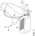
- a vehicle seat is shown with an associated seat belt device, the seat belt 1 of which is shown in the worn state, but without the vehicle occupants. Accordingly, a lap belt portion 3 of the seat belt 1 extends in the vehicle transverse direction y between a connection point inside the vehicle and a connection point A outside the vehicle Belt buckle 9 in which the belt tongue 7 is inserted. There is a third connection point outside the vehicle at about shoulder height.
- This is implemented in common practice by a deflection fitting, not shown, mounted on a vehicle pillar, not shown, around which the shoulder belt portion 5 is guided to a belt retractor 11 installed in the vehicle pillar, in which the seat belt 1 can be wound on a winding drum.
- the belt retractor 11 has a blocking unit.
- the winding drum of the belt retractor 9 is blocked with the aid of the blocking unit in the event of an accident-related vehicle deceleration in order to prevent the belt from being pulled out.
- a belt force limiting unit 13 is activated, by means of which the belt force F exerted on the vehicle occupant can be limited to a predefined force level.
- the belt buckle 9 is fastened via a wire 15 and via the belt force limiting unit 13 to a deflection fitting 19, which is attached to the in the Fig. 1 roughly indicated vehicle body 17 is mounted. Accordingly, one end of the wire rope 15 is fastened to the belt lock 9 and is guided over the deflection fitting 19 with rope deflection on the vehicle body side.
- the belt force limiting unit 13 follows, which is implemented as a piston / cylinder arrangement, with a piston tube 23 and a piston 25.
- the wire rope 15 is according to FIG Fig. 2 after the deflection fitting 19 through the piston tube 25 and connected to the piston 25, for example by stamping. This is in its illustrated rest position or non-use position with its cone-like piston tip 29 in contact with an end face of the piston tube 23 facing away from the deflection fitting 19 the conical piston tip 29, which partially protrudes into the piston tube 23.
- the blocking unit blocks the winding drum of the belt retractor 11 in order to prevent the belt from being pulled out. If the belt force F acting on the vehicle occupant exceeds a predetermined limit value, the piston 25 is displaced within the piston tube 23 by a force limiting distance s with expansion and plastic deformation. In this way, the belt force F exerted on the vehicle occupant is limited to a predefined force level.
- the maximum possible force limiting travel s max ( Figure 6 ) the piston tube length.
- a force characteristic curve is generated by means of a sheet metal clamp 28 ( Fig. 2 ) set in the Figures 2 to 4 together with an electronically controllable, pyrotechnic tensioner unit 30, forms an actuator 32.
- the actuator 32 (only indicated as a block diagram) is in signal connection with an electronic switching unit 36 via an electrical signal line 34. This is in turn connected in terms of signaling with a crash sensor system 38 and with an occupant detection sensor system 40, which are shown in FIG Fig. 1 can have, inter alia, a seat occupancy mat 42 integrated in a seat surface of the vehicle seat.
- a pre-crash phase can be determined immediately before a crash instant while driving.
- the height, body weight and / or the current seating position of the vehicle occupant placed on the vehicle seat can be determined by means of the occupant detection sensor system 40.
- the sheet metal clamp 28 is fastened to the vehicle body 17 with an upper fastening strap 44, for example via a screw connection 46.
- the sheet metal clamp 28 is according to Fig. 5 made from a simple sheet metal blank by sheet metal forming.
- the sheet metal blank shows in the Fig. 5 In the settlement, the already mentioned fastening tab 44, in which a window-like opening 46 is cut out.
- FIG Fig. 3 shown mounting position passed through the window-like opening 46, and with the formation of a sheet metal clamp winding 31, and connected to the tensioner unit 30.
- the sheet metal clamp winding 31 In the in the Fig. 3 In the non-use position shown (that is, in normal driving mode), the sheet metal clamp winding 31 is spaced from the outer circumference of the piston tube 23 by a free annular gap 52.
- a pre-crash phase can be determined by means of the crash sensor system 38.
- an above-average body weight of the current vehicle occupant can be determined, for example.
- an evaluation program module in the electronic switching unit 36 can generate an activation signal with which the tensioner unit 30 is triggered. After triggering the tensioner unit 30, the sheet metal clamp 28 is transferred to its position of use, as shown in FIG Fig. 4 is shown.
- the pull tab 48 of the sheet metal clamp 28 is subjected to a tensile force Fz ( Figure 4 ) so that the sheet metal clamp winding 31 is wound around the piston tube 23 with tensile stress, to be precise with the formation of a double tube structure, by means of which the component strength of the piston tube 23 is increased in its front area. In this way, hard or abrupt impact of the piston 25 on the movement stop 27 is prevented.
- the occupant detection sensor system 40 can determine a body weight of the current vehicle occupant that is different in weight. In this case, due to the reduced body weight of the vehicle occupant, the triggering of the tensioner unit 30 can be dispensed with.
- the sheet metal clamp winding 31 is positioned directly on the stop element 27 on the piston tube 23.
- the pipe length I R of the sheet metal clamp winding 31 is approximately 10% of the pipe length of the piston tube 23, purely by way of example.
- the level of force progressively increases, as in FIG Fig. 7 is shown.
- Such a progressive force level curve is particularly advantageous for a large, heavy vehicle occupant (95% man) in order to prevent the piston 25 from hitting the stop element 27 hard and abruptly.
Landscapes
- Engineering & Computer Science (AREA)
- Mechanical Engineering (AREA)
- General Engineering & Computer Science (AREA)
- Automotive Seat Belt Assembly (AREA)
Description
- Die Erfindung betrifft eine Sicherheitsgurteinrichtung für ein Fahrzeug nach dem Oberbegriff des Patentanspruches 1.
- Eine solche Sicherheitsgurteinrichtung kann beispielhaft einen Drei-Punkt-Sicherheitsgurt, bestehend aus einem Beckengurtanteil und einem Schultergurtanteil, sowie einen Gurtaufroller aufweisen, auf dessen Wickeltrommel der Sicherheitsgurt aufwickelbar ist. Bei einem, am Fahrzeuginsassen angelegten Sicherheitsgurt wird die Wickeltrommel des Gurtaufrollers im Falle einer unfallbedingten Fahrzeugverzögerung mit Hilfe einer darin verbauten Blockiereinrichtung blockiert, um einen Gurtauszug zu verhindern. Dadurch wirkt eine Gurtkraft auf den Fahrzeuginsassen. Um die auf den Fahrzeuginsassen wirkende Gurtkraft zu begrenzen, kann eine Gurtkraftbegrenzungseinheit vorgesehen sein, mittels der die auf einen Fahrzeuginsassen ausgeübte Gurtkraft auf ein vordefiniertes Kraftniveau begrenzt ist.
- Aus der
GB 2 327 919 A - In der
GB 2 327 919 A EP 0 568 327 A2 aufgebaute Gurtkraftbegrenzungseinheit aufgebaut, deren Kolbenrohr, über den Kraftbegrenzungsweg betrachtet, einen variierenden Innenquerschnitt aufweist. Die Bereitstellung von in der Axialrichtung variierenden Innenquerschnitten am Kolbenrohr ist jedoch mit hohem Fertigungsaufwand verbunden. Zudem ist aufgrund der in derGB 2 327 919 A - Aus der
DE 42 24 924 A1 ist eine weitere Gurtkraftbegrenzungseinheit bekannt, bei der die Materialstärke des darin verwendeten Kolbenrohrs in der Axialrichtung vergrößert wird. - Aus der
US 5 664 807 A ist eine gattungsgemäße Sicherheitsgurteinrichtung für ein Fahrzeug bekannt. Aus derEP 0 557 865 A1 , aus derDE 10 2009 030509 A1 und aus derDE 10 2009 030511 A1 sind weitere Sicherheitsgurteinrichtungen für Fahrzeug bekannt. - Die Aufgabe der Erfindung besteht darin, eine Sicherheitsgurteinrichtung für ein Fahrzeug bereitzustellen, deren Gurtkraftbegrenzungseinheit in einfacher Weise eine Anpassung der Kraftkennlinie der Gurtkraftbegrenzungseinheit ermöglicht.
- Die Aufgabe ist durch die Merkmale des Patentanspruches 1 gelöst. Bevorzugte Weiterbildungen der Erfindung sind in den Unteransprüchen offenbart.
- Die Erfindung beruht auf dem Sachverhalt, dass im Crashfall die auf den Fahrzeuginsassen wirkende Gurtkraft unabhängig von dessen Größe, Körpergewicht und/oder aktueller Sitzposition geeignet begrenzt sein muss. Vor diesem Hintergrund weist die Sicherheitsgurteinrichtung gemäß dem kennzeichnenden Teil des Patentanspruches 1 eine Schalteinheit auf, mittels der in Abhängigkeit von der Größe, dem Körpergewicht und/oder der aktuellen Sitzposition des Fahrzeuginsassen ein Kraftniveau-Verlauf über den Kraftbegrenzungsweg im Kolbenrohr vordefinierbar ist. Auf diese Weise kann das Kraftbegrenzungsniveau zu einem bestimmten, frei wählbaren Zeitpunkt gezielt auf das Körpergewicht, die Größe und/oder die Sitzposition des Fahrzeuginsassen angepasst werden.
- Die gezielte Anpassung des Kraftbegrenzungsniveaus (das heißt des Kraftniveau-Verlaufes) über den Kraftbegrenzungsweg im Kolbenrohr wird unmittelbar vor einem Crash-Zeitpunkt in einer Pre-Crash-Phase selbsttätig von der Schalteinheit durchgeführt.
- Bevorzugt zielt die Erfindung darauf ab, dass ein hartes und abruptes Anstoßen des Kolbens an einem Bewegungsanschlag am Ende des Kraftbegrenzungsweges verhindert wird, um die Belastung - vorrangig bei großen schweren Fahrzeuginsassen (das heißt 95%-Mann) - zu reduzieren. Um in diesem Fall das Kraftniveau zu erhöhen bzw. zu schalten, kann eine schleifenartig geformte Schelle bereitgestellt sein, die um das Kolbenrohr umwickelt ist. Die Schelle ist grundsätzlich variabel in ihrer Breite sowie in ihrer axialen Positionierung am Kolbenrohr (das heißt vorne, mittig oder hinten). Im Falle des oben erwähnten 95%-Mannes ist es bevorzugt, wenn die Schelle hinten platziert ist, um im Kraftniveau-Verlauf eine Progressivität zu erzeugen. In einer Nichtgebrauchslage kann ein Freiraum zwischen der Schelle und dem Kolbenrohr vorhanden sein und zum Beispiel zirka 1,0 mm betragen. Eine Kraftschaltung von ihrer Nichtgebrauchslage in die Gebrauchslage erfolgt beispielhaft pyrotechnisch, in dem an einer Zuglasche der Schelle eine Zugkraft ausgeübt wird. Die Blechdicke der Schelle kann beispielhaft 1,0 mm betragen.
- Nachfolgend sind weitere Aspekte der Erfindung detailliert erläutert: So ist die Schalteinheit in Signalverbindung mit einer Crashsensorik und mit einer Insassenerkennungssensorik. Mittels der Insassenerkennungssensorik wird die Größe, das Gewicht und/oder die Sitzposition des Fahrzeuginsassen ermittelt. Zusätzlich wird mittels der Schalteinheit ein Stellglied angesteuert, mit dem in Abhängigkeit von der Größe, dem Gewicht oder der Sitzposition des aktuellen Fahrzeuginsassen eine Bauteilfestigkeit des Kolbenrohrs reduziert oder erhöht wird. Die Ansteuerung des Stellglieds wird erst dann freigegeben, wenn mittels der Crashsensorik das Vorliegen einer Pre-Crash-Phase bestimmt worden ist.
- Bei Ermittlung eines überdurchschnittlich hohen Körpergewichts des Fahrzeuginsassen (das heißt 95%-Mann) kann exemplarisch die Schalteinheit unter Ansteuerung des Stellglieds die Kolbenrohr-Bauteilfestigkeit erhöhen. Umgekehrt kann bei Ermittlung eines unterdurchschnittlich geringen Körpergewichts des Fahrzeuginsassen (das heißt 5%-Frau) die Schalteinheit unter Ansteuerung des Stellglieds die Kolbenrohr-Bauteilsteifigkeit reduzieren. Alternativ kann bei Ermittlung eines unterschiedlich geringen Körpergewichts des Fahrzeuginsassen die Schalteinheit auch deaktiviert bleiben, das heißt keine Ansteuerung des Stellglieds erfolgen.
- In einer technischen Realisierung der Erfindung kann das Stellglied ein schleifenartiges Zugband aufweisen. Das Zugband kann in einem Fahrzeug-Normalbetrieb (das heißt in einer Nichtgebrauchslage) lose mit Bewegungsspiel um das Kolbenrohr gewickelt sein und somit keinen Einfluss auf die Kolbenrohr-Bauteilfestigkeit ausüben. Erst bei geeigneter Ansteuerung vom Schaltelement kann das Zugband in eine Gebrauchslage überführt werden. In der Gebrauchslage kann das Zugband unter Bildung einer Doppelrohrstruktur mit einer Zugspannung um das Kolbenrohr gewickelt sein, um die Kolbenrohr-Bauteilfestigkeit zu erhöhen.
- In einer einfachen bevorzugten Ausführung kann das Stellglied eine elektrisch auslösbare, pyrotechnische Straffereinheit aufweisen, mittels der das Zugband in seiner Gebrauchslage mit der Zugspannung beaufschlagbar ist. Das Zugband kann bevorzugt eine Blechschelle sein, die in fertigungstechnisch einfacher Weise durch Blechumformung hergestellt ist. Die Blechschelle kann in einer Abwicklung mit Bezug auf ihre Längsachse spiegelsymmetrisch ausgeführt sein und eine breite Befestigungslasche mit einem fensterartigen Durchbruch aufweisen. Im weiteren Verlauf in der Längserstreckungsrichtung kann sich an die breite Befestigungslasche eine schmale Zuglasche anschließen. Im Montagezustand kann die Zuglasche unter Bildung einer Schleife (nachfolgend auch als Windung oder Wicklung bezeichnet) durch den fensterartigen Durchbruch geführt sein und an der Straffereinheit angebunden sein. Die Schleife (das heißt Windung oder Wicklung) umfasst dabei außenseitig das Kolbenrohr.
- Die oben erwähnte Straffereinheit kann wiederum signaltechnisch mit der elektronischen Schalteinheit verbunden sein und von dieser ansteuerbar sein. Die Ansteuerung der Straffereinheit erfolgt bevorzugt erst dann, wenn mittels der Crashsensorik eine Pre-Crash-Phase festgestellt worden ist.
- Der Zusammenbau des Zugbandes mit dem Kolbenrohr erfolgt in fertigungstechnisch einfacher Weise sowie ohne großen Werkzeugaufwand. Bevorzugt ist die mittels der Zuglasche gebildete Wicklung oder Windung lediglich ringförmig (das heißt im Vergleich zum Kolbenrohr sehr geringer Rohrlänge) ausgeführt. Alternativ dazu kann die Zugband-Wicklung eine größere Rohrlänge aufweisen, die jedoch deutlich kleiner als die Rohrlänge des Kolbenrohrs ausgelegt sein kann. Entscheidend ist lediglich, dass im Zusammenbauzustand das Kolbenrohr zumindest einen, von der Zugband-Wicklung umfassten Kolbenrohrabschnitt sowie zumindest einen von der Zugband-Wicklung freigelegten Kolbenrohrabschnitt aufweist.
- Die Zugband-Wicklung kann im Fertigungsprozess leichtgängig in ihre vordefinierte Axialposition gebracht werden. In der vorgegebenen Axialposition kann die Zugband-Wicklung in beliebiger Weise über ihre Befestigungslasche an einem angrenzenden Bauteil, insbesondere am Fahrzeugaufbau, fixiert werden, zum Beispiel durch eine kraft-, stoff- und/oder formschlüssige Verbindung. Fertigungstechnisch vorteilhaft kann in der Nichtgebrauchslage, das heißt im normalen Fahrbetrieb auf eine feste Verbindung unmittelbar zwischen der Zugband-Wicklung und dem Kolbenrohr verzichtet werden, da die Zugband-Wicklung das Kolbenrohr umfangsseitig mit einem zwischengeschalteten Ringspalt umgreift.
- In einer technischen Umsetzung kann das Kolbenrohr sowohl innen- als auch außenumfangsseitig über dessen gesamte Rohrlänge mit einem konstanten Innen- und Außendurchmesser (das heißt mit konstantem Innenquerschnitt) sowie bevorzugt glattzylindrisch ausgebildet sein. Auf diese Weise kann das Kolbenrohr in einer einfachen zylindrischen Bauteilgeometrie, das heißt ohne spezielle Innen- oder Außenstruktur, vorgehalten werden. In gleicher Weise kann auch die Zugband-Wicklung innen- und außenseitig glattflächig ausgeführt sein.
- Das Zugband kann bevorzugt fertigungstechnisch einfach durch eine Blechumformung als eine Blechschelle realisiert sein.
- Mittels der Axialposition der Zugband-Wicklung auf dem Kolbenrohr wird die Kraftkennlinie der Gurtkraftbegrenzungseinheit festgelegt. Exemplarisch kann die Gurtkraftbegrenzungseinheit eine progressive, eine degressive oder eine wellenförmige Kraftkennlinie aufweisen. Für einen progressiven Kraftniveau-Verlauf kann die Zugband-Wicklung am Ende des Kraftbegrenzungswegs auf dem Kolbenrohr positioniert sein. Anstelle dessen kann für einen degressiven Kraftniveau-Verlauf die Zugband-Wicklung zu Beginn des Kraftbegrenzungsweg auf dem Kolbenrohr befestigt sein. Für einen wellenförmigen Kraftniveau-Verlauf kann die Zugband-Wicklung auf einem Mittelabschnitt des Kolbenrohrs befestigt sein.
- In einer technischen Umsetzung ist das Kolbenrohr sowohl innen- als auch außenumfangsseitig über dessen gesamte Rohrlänge mit einem konstanten Innen- und Außendurchmesser (das heißt mit konstantem Innenquerschnitt) sowie bevorzugt glattzylindrisch ausgebildet. Auf diese Weise kann das Kolbenrohr in einer einfachen zylindrischen Bauteilgeometrie, das heißt ohne spezielle Innen- oder Außenstruktur, vorgehalten werden. In gleicher Weise kann auch das die Zugband-Wicklung sowohl innen- als auch außenumfangsseitig über deren gesamte Rohrlänge mit einem konstanten Innen- und Außendurchmesser sowie ebenfalls glattzylindrisch ausgeführt sein.
- Mittels der Axialposition der Zugband-Wicklung auf dem Kolbenrohr wird die Kraftkennlinie der Gurtkraftbegrenzungseinheit festgelegt. Exemplarisch kann die Gurtkraftbegrenzungseinheit eine progressive, eine degressive oder eine wellenförmige Kraftkennlinie aufweisen. Für einen progressiven Kraftniveau-Verlauf kann die Zugband-Wicklung am Ende des Kraftbegrenzungswegs auf dem Kolbenrohr befestigt sein. Anstelle dessen kann für einen degressiven Kraftniveau-Verlauf die Zugband-Wicklung zu Beginn des Kraftbegrenzungswegs auf dem Kolbenrohr befestigt sein. Für einen wellenförmigen Kraftniveau-Verlauf kann die Zugband-Wicklung auf einem Mittelabschnitt des Kolbenrohrs befestigt sein.
- Die erfindungsgemäße Gurtkraftbegrenzungseinheit kann in einer Sicherheitsgurteinrichtung realisiert sein, die exemplarisch einen Drei-Punkt-Sicherheitsgurt mit einem Beckengurtanteil sowie einem Schultergurtanteil aufweist. Im angelegten Zustand kann der Sicherheitsgurt mittels einer Gurtzunge in lösbarer Verbindung mit einem fahrerseitigen Gurtschloss sein. Das Gurtschloss kann über ein Drahtseilelement sowie über die Kraftbegrenzungseinheit am Fahrzeugaufbau befestigt sein. In diesem Fall kann das Drahtseilelement mit seinem Seilende durch das Kolbenrohr der Gurtkraftbegrenzungseinheit geführt sein und am Kolben angebunden sein. Das Drahtseilelement kann ausgehend vom Gurtschloss durch einen fahrzeugaufbauseitigen Umlenkbeschlag mit Seilumlenkung geführt sein, wobei der Umlenkbeschlag aufbaufest an der Fahrzeugkarosserie montierbar ist. Im weiteren Verlauf kann sich am Umlenkbeschlag die Gurtkraftbegrenzungseinheit anschließen. In diesem Fall kann der Umlenkbeschlag eine Stützkontur aufweisen, gegen die das Kolbenrohr mit seiner dem Kolben abgewandten Seite im Gurtkraftbegrenzungsfall abgestützt werden kann.
- Nachfolgend ist ein Ausführungsbeispiel der Erfindung anhand der beigefügten Figuren detailliert beschrieben.
- Es zeigen:
- Fig. 1
- in einer perspektivischen Darstellung eine Sicherheitsgurteinrichtung mit angelegtem Sicherheitsgurt, jedoch unter Weglassung des Fahrzeuginsassen;
- Fig. 2
- eine Baueinheit, bestehend aus dem Gurtschloss der Sicherheitsgurteinrichtung und der Gurtkraftbegrenzungseinheit, in Alleinstellung;
- Fig. 3
- in einer Schnittdarstellung entlang der Schnittebene A-A aus der
Fig. 2 die Gurtkraftbegrenzungseinheit in einer Nichtgebrauchslage; - Fig. 4
- in einer Ansicht entsprechend der
Fig. 3 die Gurtkraftbegrenzungseinheit in einer Gebrauchslage; - Fig. 5
- eine Blechschelle in einer Abwicklung;
- Fig. 6
- in einer Ansicht entsprechend der
Fig. 2 eine Gurtkraftbegrenzungseinheit in teilweiser Schnittdarstellung sowie mit einer Blechschellen-Wicklung, die unmittelbar am Ende des Kraftbegrenzungsweges auf dem Kolbenrohr positioniert ist; und - Fig. 7
- eine Kraftkennlinie der in der
Fig. 6 gezeigten Gurtkraftbegrenzungseinheit. - In der
Fig. 1 ist ein Fahrzeugsitz mit zugeordneter Sicherheitsgurteinrichtung gezeigt, deren Sicherheitsgurt 1 im angelegten Zustand, jedoch ohne Fahrzeuginsassen, dargestellt ist. Demzufolge erstreckt sich in der Fahrzeugquerrichtung y ein Beckengurtanteil 3 des Sicherheitsgurtes 1 zwischen einem fahrzeuginneren Anbindungspunkt und einem fahrzeugäußeren Anbindungspunkt A. Der auf Beckenhöhe befindliche fahrzeuginnere Anbindungspunkt A ist lösbar ausgeführt, und zwar mit einer am Sicherheitsgurt 1 gehalterten Gurtzunge 7 und einem damit zusammenwirkenden, fahrzeugfesten Gurtschloss 9, in dem die Gurtzunge 7 eingesteckt ist. In etwa auf Schulterhöhe befindet sich ein dritter fahrzeugäußerer Anbindungspunkt. Dieser ist in gängiger Praxis durch einen nicht gezeigten, an einer nicht dargestellten Fahrzeugsäule montierten Umlenkbeschlag realisiert, um den der Schultergurtanteil 5 bis zu einem in der Fahrzeugsäule verbauten Gurtaufroller 11 geführt ist, in der der Sicherheitsgurt 1 auf einer Wickeltrommel aufwickelbar ist. Der Gurtaufroller 11 weist in gängiger Praxis eine Blockiereinheit auf. Bei einem, am Fahrzeuginsassen angelegten Sicherheitsgurt 1 wird die Wickeltrommel des Gurtaufrollers 9 im Fall einer unfallbedingten Fahrzeugverzögerung mit Hilfe der Blockiereinheit blockiert, um einen Gurtauszug zu verhindern. Dadurch wirkt eine Gurtkraft F (Fig. 1 ) vom Sicherheitsgurt 1 auf den Fahrzeuginsassen. Übersteigt die Gurtkraft F einen vorgegebenen Grenzwert, so wird eine Gurtkraftbegrenzungseinheit 13 aktiv, mittels der die auf den Fahrzeuginsassen ausgeübte Gurtkraft F auf ein vordefiniertes Kraftniveau begrenzbar ist. - Wie aus der
Fig. 2 hervorgeht, ist das Gurtschloss 9 über ein Drahtseil 15 sowie über die Gurtkraftbegrenzungseinheit 13 an einem Umlenkbeschlag 19 befestigt, der am in derFig. 1 grob angedeuteten Fahrzeugaufbau 17 montiert ist. Demzufolge ist das Drahtseil 15 mit einem Ende am Gurtschloss 9 befestigt und über den fahrzeugaufbauseitigen Umlenkbeschlag 19 mit Seilumlenkung geführt. Im weiteren Verlauf schließt sich die Gurtkraftbegrenzungseinheit 13 an, die als eine Kolben-/Zylinder-Anordnung realisiert ist, und zwar mit einem Kolbenrohr 23 und einem Kolben 25. Das Drahtseil 15 ist gemäß derFig. 2 nach dem Umlenkbeschlag 19 durch das Kolbenrohr 25 geführt und am Kolben 25, zum Beispiel durch Verprägung, angebunden. Dieser ist in der seiner dargestellten Ruhelage oder Nichtgebrauchslage mit seiner konusartigen Kolbenspitze 29 in Anlage mit einer vom Umlenkbeschlag 19 abgewandten Stirnseite des Kolbenrohrs 23. Von daher ist das Kolbenrohr 23 in der Axialrichtung zwischen einem topfförmigen Anschlagelement 27, das am Umlenkbeschlag 19 ausgebildet ist, und der konusartigen Kolbenspitze 29 angeordnet, die teilweise in das Kolbenrohr 23 einragt. - Bei einer unfallbedingten Fahrzeugverzögerung blockiert die Blockiereinheit die Wickeltrommel des Gurtaufrollers 11, um einen Gurtauszug zu verhindern. Übersteigt die auf den Fahrzeuginsassen wirkende Gurtkraft F einen vorgegebenen Grenzwert, so wird der Kolben 25 unter Aufweitung sowie plastischer Verformung um einen Kraftbegrenzungsweg s innerhalb des Kolbenrohrs 23 verlagert. Auf diese Weise wird die auf den Fahrzeuginsassen ausgeübte Gurtkraft F auf ein vordefiniertes Kraftniveau begrenzt. Dabei entspricht der maximal mögliche Kraftbegrenzungsweg smax (
Figur 6 ) der Kolbenrohrlänge. - Das von der Gurtkraftbegrenzungseinheit 13 über den Kraftbegrenzungsweg s (
Fig. 7 ) bereitgestellte Gurtkraftniveau kann in einer Kraftkennlinie wiedergegeben werden, wie sie später anhand derFig. 6 und 7 erläutert wird. Eine solche Kraftkennlinie wird erfindungsgemäß mittels einer Blechschelle 28 (Fig. 2 ) eingestellt, die in denFiguren 2 bis 4 zusammen mit einer elektronisch ansteuerbaren, pyrotechnischen Straffereinheit 30 ein Stellglied 32 bildet. Das Stellglied 32 (nur als Blockschaltbild angedeutet) ist über eine elektrische Signalleitung 34 in Signalverbindung mit einer elektronischen Schalteinheit 36. Diese ist wiederum signaltechnisch mit einer Crashsensorik 38 und mit einer Insassenerkennungssensorik 40 in Verbindung, die in derFig. 1 unter anderem eine in einer Sitzfläche des Fahrzeugsitzes integrierte Sitzbelegungsmatte 42 aufweisen kann. - Mit Hilfe der Crashsensorik 38 kann im Fahrbetrieb eine Pre-Crash-Phase unmittelbar vor einem Crash-Zeitpunkt bestimmt werden. Mittels der Insassenerkennungssensorik 40 kann die Größe, das Körpergewicht und/oder die aktuelle Sitzposition des auf dem Fahrzeugsitz platzierten Fahrzeuginsassen ermittelt werden. Wie aus der
Fig. 2 und3 weiter hervorgeht, ist die Blechschelle 28 mit einer oberen Befestigungslasche 44 am Fahrzeugaufbau 17 zum Beispiel über eine Schraubverbindung 46 befestigt. Die Blechschelle 28 ist gemäß derFig. 5 aus einem einfachen Blechzuschnitt durch Blechumformung hergestellt. Der Blechzuschnitt weist in derFig. 5 in Abwicklung die bereits erwähnte Befestigungslasche 44 auf, in der ein fensterartiger Durchbruch 46 ausgeschnitten ist. Im weiteren Verlauf in der Längserstreckungsrichtung L nach unten folgt eine schmale Zuglasche 48. Diese ist in der in derFig. 3 gezeigten Montagelage durch den fensterartigen Durchbruch 46 hindurchgeführt, und zwar unter Bildung einer Blechschellen-Wicklung 31, und an der Straffereinheit 30 angebunden. In der in derFig. 3 gezeigten Nichtgebrauchslage (das heißt im normalen Fahrbetrieb) ist die Blechschellen-Wicklung 31 um einen freien Ringspalt 52 vom Außenumfang des Kolbenrohrs 23 beabstandet. - Im normalen Fahrbetrieb hat die Blechschelle 28 daher keinen Einfluss auf die Bauteilsteifigkeit des Kolbenrohrs 23. In einer Crashsituation kann dagegen die folgende Kraftschaltung erfolgen: So kann zunächst mittels der Crashsensorik 38 zunächst eine Pre-Crash-Phase festgestellt werden. Mittels der Insassenerkennungssensorik 40 kann exemplarisch ein überdurchschnittlich hohes Körpergewicht des aktuellen Fahrzeuginsassen ermittelt worden sein. In diesem Fall kann ein Auswerte-Programmbaustein in der elektronischen Schalteinheit 36 ein Aktivierungssignal generieren, mit dem die Straffereinheit 30 ausgelöst wird. Nach der Auslösung der Straffereinheit 30 ist die Blechschelle 28 in ihre Gebrauchslage überführt, wie sie in der
Fig. 4 gezeigt ist. Demzufolge wird die Zuglasche 48 der Blechschelle 28 mit einer Zugkraft Fz (Figur 4 ) beaufschlagt, so dass die Blechschellen-Wicklung 31 mit Zugspannung um das Kolbenrohr 23 gewickelt ist, und zwar unter Bildung einer Doppelrohrstruktur, mittels der die Bauteilfestigkeit des Kolbenrohrs 23 in dessen vorderem Bereich erhöht ist. Auf diese Weise wird ein hartes oder abruptes Anstoßen des Kolbens 25 am Bewegungsanschlag 27 verhindert. - In einer alternativen Crashsituation kann die Insassenerkennungssensorik 40 ein unterschiedlich geringes Körpergewicht des aktuellen Fahrzeuginsassen ermitteln. In diesem Fall kann aufgrund des reduzierten Körpergewichts des Fahrzeuginsassen auf die Auslösung der Straffereinheit 30 verzichtet werden.
- In der
Fig. 6 ist die Blechschellen-Wicklung 31 unmittelbar am Anschlagelement 27 auf dem Kolbenrohr 23 positioniert. Die Rohrlänge IR der Blechschellen-Wicklung 31 beträgt rein beispielhaft etwa 10% der Rohrlänge des Kolbenrohrs 23. Entsprechend weist das Kolbenrohr 23 einen von der Blechschellen-Wicklung 31 umfassten Rohrabschnitt sowie einen von der Blechschellen-Wicklung 31 freigelegten Rohrabschnitt auf. Bei der in derFig. 6 gezeigten Anordnung steigt in einem Gurtkraftbegrenzungsfall (das heißt in der oben erwähnten Pre-Crash-Phase), bei dem der Kolben 25 über den maximalen Kraftbegrenzungsweg smax verlagert wird, das Kraftniveau progressiv an, wie es in derFig. 7 gezeigt ist. Ein solcher progressiver Kraftniveau-Verlauf ist insbesondere bei einem großen, schweren Fahrzeuginsassen (95%-Mann) vorteilhaft, um ein hartes sowie abruptes Anstoßen des Kolbens 25 am Anschlagelement 27 zu verhindern. -
- 1
- Sicherheitsgurt
- 3
- Beckengurtanteil
- 5
- Schultergurtanteil
- 7
- Gurtzunge
- 9
- Gurtschloss
- 11
- Gurtaufroller
- 13
- Gurtkraftbegrenzungseinheit
- 15
- Drahtseilelement
- 17
- Fahrzeugaufbau
- 19
- Umlenkbeschlag
- 23
- Kolbenrohr
- 25
- Kolben
- 27
- Anschlagelement
- 28
- Blechschelle
- 29
- konusartige Kolbenspitze
- 30
- Straffereinheit
- 31
- Blechschellen-Wicklung bzw. Zugband-Wicklung
- 32
- Stellglied
- 33
- Befestigungslasche
- 34
- elektrische Signalleitung
- 35
- Schraubverbindung
- 36
- Schalteinheit
- 38
- Crashsensorik
- 39
- Anbindungspunkt
- 40
- Insassenerkennungssensorik
- 42
- Sitzbelegungsmatte
- 44
- Befestigungslasche
- 46
- fensterartiger Durchbruch
- 48
- Zuglasche
- 52
- Ringspalt
- s
- Kraftbegrenzungsweg
- A
- lösbarer Anbindungspunkt
- F
- Gurtkraft
- Fz
- Zugkraft
Claims (7)
- Sicherheitsgurteinrichtung für ein Fahrzeug, mit einer Gurtkraftbegrenzungseinheit (13), die als eine Kolben-Zylinder-Anordnung aus einem Kolbenrohr (23) und aus einem Kolben (25) aufgebaut ist, der in einem Gurtkraftbegrenzungsfall, insbesondere Crashfall, unter Aufweitung sowie plastischer Verformung um einen Kraftbegrenzungsweg (s) im Kolbenrohr (23) verlagerbar ist, so dass die auf einen Fahrzeuginsassen ausgeübte Gurtkraft (F) auf ein vordefiniertes Kraftniveau begrenzt ist, dadurch gekennzeichnet, dass die Sicherheitsgurteinrichtung eine Schalteinheit (36) aufweist, mittels der in Abhängigkeit von der Größe, dem Gewicht und/oder der Sitzposition des Fahrzeuginsassen ein Kraftniveau-Verlauf (F(s)) über den Kraftbegrenzungsweg (s) vordefinierbar ist, und dass die Schalteinheit (36) in Signalverbindung mit einer Crashsensorik (38) und mit einer Insassenerkennungssensorik (40) ist, mittels der die Größe, das Gewicht und/oder die Sitzposition des Fahrzeuginsassen ermittelbar ist, und dass mittels der Schalteinheit (36) bei Vorliegen einer Pre-Crash-Phase ein Stellglied (32) ansteuerbar ist, mit dem in Abhängigkeit von der Größe/dem Gewicht oder der Sitzposition des Fahrzeuginsassen eine Bauteilfestigkeit des Kolbenrohrs (23) reduzierbar/erhöhbar ist.
- Sicherheitsgurteinrichtung nach Anspruch 1, dadurch gekennzeichnet, dass das Stellglied (32) ein schleifenartiges Zugband (28) aufweist, und dass das Zugband (28) in einem Fahrzeug-Normalbetrieb, das heißt in einer Nichtgebrauchslage lose mit Bewegungsspiel (52) um das Kolbenrohr (23) gewickelt ist und keinen Einfluss auf die Bauteilfestigkeit des Kolbenrohrs (23) ausübt, und dass das Zugband (28) bei entsprechender Ansteuerung von der Schalteinheit (36), das heißt in einer Gebrauchslage, unter Bildung einer Doppelrohrstruktur mit Zugspannung um das Kolbenrohr (23) gewickelt ist und die Bauteilfestigkeit des Kolbenrohrs (23) erhöht.
- Sicherheitsgurteinrichtung nach Anspruch 2, dadurch gekennzeichnet, dass das Stellglied (32) eine insbesondere elektrisch auslösbare, pyrotechnische Straffereinheit (30) aufweist, und dass das Zugband (28) mit einer Befestigungslasche (44) am Fahrzeugaufbau (17) befestigbar ist und mit der anderen Zuglasche (48) an der Straffereinheit (30) signaltechnisch mit der Schalteinheit (30) verbunden ist und von dieser ansteuerbar ist.
- Sicherheitsgurteinrichtung nach Anspruch 2 oder 3, dadurch gekennzeichnet, dass das Zugband (28) eine Blechschelle ist, die in einer Abwicklung eine breite Befestigungslasche (44) mit einem fensterartigen Durchbruch (46) aufweist, wobei die Befestigungslasche (44) im weiteren Verlauf in einer Längserstreckungsrichtung in eine schmale Zuglasche (48) übergeht, und wobei die Zuglasche (48) unter Bildung einer Zugband-Wicklung (31), durch die sich das Kolbenrohr (23) erstreckt, durch den fensterartigen Durchbruch (46) geführt ist und an der Straffereinheit (30) angebunden ist.
- Sicherheitsgurteinrichtung nach einem der vorhergehenden Ansprüche, dadurch gekennzeichnet, dass das Kolbenrohr (23) innen- und/oder außenumfangsseitig über dessen gesamte Rohrlänge mit konstantem Innen- und Außendurchmesser und/oder glattzylindrisch ausgebildet sind, und/oder dass die Zugband-Wicklung (31) innen- und/oder außenumfangsseitig über dessen gesamte Rohrlänge (IR) mit konstantem Innen- und Außendurchmesser und/oder glattzylindrisch ausgebildet ist.
- Sicherheitsgurteinrichtung nach einem der Ansprüche 4 oder 5, dadurch gekennzeichnet, dass für einen progressiven Kraftniveau-Verlauf die Zugband-Wicklung (31) am Ende (smax) des Kraftbegrenzungswegs (s) auf dem Kolbenrohr (23) positioniert ist, oder dass für einen degressiven Kraftniveau-Verlauf die Zugband-Wicklung (31) zu Beginn (so) des Kraftbegrenzungswegs (s) auf dem Kolbenrohr (23) positioniert ist, oder dass für einen wellenförmigen Kraftniveau-Verlauf die Zugband-Wicklung (31) auf einem Mittelabschnitt des Kolbenrohrs (23) positioniert ist.
- Sicherheitsgurteinrichtung nach einem der vorhergehenden Ansprüche, dadurch gekennzeichnet, dass ein Sicherheitsgurt (1) im angelegten Zustand mit einer Gurtzunge (7) in lösbarer Verbindung mit einem fahrzeugseitigen Gurtschloss (9) ist, das über ein Drahtseilelement (15) und über die Kraftbegrenzungseinheit (13) am Fahrzeugaufbau (17) befestigbar ist, und dass das Drahtseilelement (15) mit seinem Seilende durch das Kolbenrohr (23) geführt ist und am Kolben (25) angebunden ist.
Applications Claiming Priority (2)
| Application Number | Priority Date | Filing Date | Title |
|---|---|---|---|
| DE102017204508.6A DE102017204508A1 (de) | 2017-03-17 | 2017-03-17 | Sicherheitsgurteinrichtung für ein Fahrzeug |
| PCT/EP2018/056618 WO2018167251A1 (de) | 2017-03-17 | 2018-03-16 | Sicherheitsgurteinrichtung für ein fahrzeug |
Publications (2)
| Publication Number | Publication Date |
|---|---|
| EP3609744A1 EP3609744A1 (de) | 2020-02-19 |
| EP3609744B1 true EP3609744B1 (de) | 2020-12-23 |
Family
ID=63371952
Family Applications (1)
| Application Number | Title | Priority Date | Filing Date |
|---|---|---|---|
| EP18712173.6A Active EP3609744B1 (de) | 2017-03-17 | 2018-03-16 | Sicherheitsgurteinrichtung für ein fahrzeug |
Country Status (3)
| Country | Link |
|---|---|
| EP (1) | EP3609744B1 (de) |
| DE (1) | DE102017204508A1 (de) |
| WO (1) | WO2018167251A1 (de) |
Family Cites Families (8)
| Publication number | Priority date | Publication date | Assignee | Title |
|---|---|---|---|---|
| DE4206117C2 (de) * | 1992-02-27 | 1994-01-20 | Trw Repa Gmbh | Energiewandler in einem Rückhaltesystem für Fahrzeuginsassen |
| GB9209187D0 (en) | 1992-04-29 | 1992-06-17 | Bsrd Ltd | Vehicle passenger restraint system |
| DE4224924A1 (de) | 1992-07-28 | 1994-02-03 | Trw Repa Gmbh | Sicherheitsgurt-Rückhaltesystem mit Gurtstraffer |
| US5531479A (en) * | 1995-01-20 | 1996-07-02 | Trw Vehicle Safety Systems Inc. | Vehicle seat belt restraint system |
| DE19511457A1 (de) * | 1995-03-29 | 1996-10-02 | Trw Repa Gmbh | Kraftbegrenzung in einem Insassen-Rückhaltesystem |
| GB9715937D0 (en) | 1997-07-28 | 1997-10-01 | Alliedsignal Ltd | Pretensioner |
| US7784831B2 (en) * | 2008-06-27 | 2010-08-31 | Gm Global Technology Operations, Inc. | Seat belt load limiting device |
| US8091923B2 (en) * | 2008-06-27 | 2012-01-10 | GM Global Technology Operations LLC | Adaptive seat belt load limiter and method |
-
2017
- 2017-03-17 DE DE102017204508.6A patent/DE102017204508A1/de not_active Withdrawn
-
2018
- 2018-03-16 EP EP18712173.6A patent/EP3609744B1/de active Active
- 2018-03-16 WO PCT/EP2018/056618 patent/WO2018167251A1/de not_active Ceased
Non-Patent Citations (1)
| Title |
|---|
| None * |
Also Published As
| Publication number | Publication date |
|---|---|
| WO2018167251A1 (de) | 2018-09-20 |
| DE102017204508A1 (de) | 2018-09-20 |
| EP3609744A1 (de) | 2020-02-19 |
Similar Documents
| Publication | Publication Date | Title |
|---|---|---|
| DE102005025570B4 (de) | Kindersitz für Fahrzeuge | |
| EP3571098B1 (de) | Sicherheitsgurteinrichtung für ein fahrzeug | |
| EP2785566A1 (de) | Gurtaufroller mit zwei parallel wirkenden kraftbegrenzungseinrichtungen | |
| DE10204475B4 (de) | Gurtstraffer | |
| DE102020107973A1 (de) | Sicherheitsgurtaufrollerbaugruppe | |
| DE69631966T2 (de) | Sicherheitsgurtaufroller | |
| DE102014118154B4 (de) | Ankergurtstraffer für ein Fahrzeug | |
| DE3044951A1 (de) | Rueckstrammer fuer einen sicherheitsgurt | |
| DE69717082T2 (de) | Sicherheitsgurtsystem | |
| WO2007025958A1 (de) | Sicherheitsgurtsystem | |
| DE2726096A1 (de) | Spannvorrichtung fuer sicherheitsgurte | |
| EP4211004B1 (de) | Gurtaufroller | |
| EP3609744B1 (de) | Sicherheitsgurteinrichtung für ein fahrzeug | |
| DE102007033154B4 (de) | Sicherheitsgurtsystem für ein Kraftfahrzeug | |
| EP0778182B1 (de) | Rückhaltesystem in einem Fahrzeug | |
| DE102006027897A1 (de) | Sicherheitsgurteinrichtung für ein Kraftfahrzeug | |
| DE102008000981B4 (de) | Gurtaufrolleinheit sowie Verfahren zum Aufrollen von mindestens einem Gurtband sowie Gurtsystem für ein Insassenschutzsystem in einem Fahrzeug mit mindestens einer solchen Gurtaufrolleinheit | |
| EP3096984B1 (de) | Gurtstraffereinheit für eine fahrzeug-sicherheitsgurtanordnung | |
| EP2470400B1 (de) | Sicherheitsgurteinrichtung für ein fahrzeug | |
| DE102022131560B3 (de) | Kraftbegrenzer | |
| DE102009014190A1 (de) | Vorrichtung zum Ermöglichen einer Translationsbewegung eines Gurtschlosses in einem Fahrzeug | |
| DE29913227U1 (de) | Gurtstrafferrohr für eine pyrotechnische Gurtstraffungsvorrichtung | |
| DE102008041508A1 (de) | Gurtaufrolleinheit sowie Gurtsystem für ein Insassenschutzsystem in einem Fahrzeug mit mindestens einer solchen Gurtaufrolleinheit | |
| DE102008043019A1 (de) | Gurtsystem für ein Insassenschutzsystem in einem Fahrzeug | |
| DE102006036336A1 (de) | Verfahren zum Betreiben einer Insassenrückhaltevorrichtung und Insassenrückhaltevorrichtung |
Legal Events
| Date | Code | Title | Description |
|---|---|---|---|
| STAA | Information on the status of an ep patent application or granted ep patent |
Free format text: STATUS: UNKNOWN |
|
| STAA | Information on the status of an ep patent application or granted ep patent |
Free format text: STATUS: THE INTERNATIONAL PUBLICATION HAS BEEN MADE |
|
| PUAI | Public reference made under article 153(3) epc to a published international application that has entered the european phase |
Free format text: ORIGINAL CODE: 0009012 |
|
| STAA | Information on the status of an ep patent application or granted ep patent |
Free format text: STATUS: REQUEST FOR EXAMINATION WAS MADE |
|
| 17P | Request for examination filed |
Effective date: 20200110 |
|
| AK | Designated contracting states |
Kind code of ref document: A1 Designated state(s): AL AT BE BG CH CY CZ DE DK EE ES FI FR GB GR HR HU IE IS IT LI LT LU LV MC MK MT NL NO PL PT RO RS SE SI SK SM TR |
|
| AX | Request for extension of the european patent |
Extension state: BA ME |
|
| DAV | Request for validation of the european patent (deleted) | ||
| DAX | Request for extension of the european patent (deleted) | ||
| GRAP | Despatch of communication of intention to grant a patent |
Free format text: ORIGINAL CODE: EPIDOSNIGR1 |
|
| STAA | Information on the status of an ep patent application or granted ep patent |
Free format text: STATUS: GRANT OF PATENT IS INTENDED |
|
| INTG | Intention to grant announced |
Effective date: 20201008 |
|
| GRAS | Grant fee paid |
Free format text: ORIGINAL CODE: EPIDOSNIGR3 |
|
| GRAA | (expected) grant |
Free format text: ORIGINAL CODE: 0009210 |
|
| STAA | Information on the status of an ep patent application or granted ep patent |
Free format text: STATUS: THE PATENT HAS BEEN GRANTED |
|
| AK | Designated contracting states |
Kind code of ref document: B1 Designated state(s): AL AT BE BG CH CY CZ DE DK EE ES FI FR GB GR HR HU IE IS IT LI LT LU LV MC MK MT NL NO PL PT RO RS SE SI SK SM TR |
|
| REG | Reference to a national code |
Ref country code: GB Ref legal event code: FG4D Free format text: NOT ENGLISH |
|
| REG | Reference to a national code |
Ref country code: DE Ref legal event code: R096 Ref document number: 502018003407 Country of ref document: DE |
|
| REG | Reference to a national code |
Ref country code: AT Ref legal event code: REF Ref document number: 1347413 Country of ref document: AT Kind code of ref document: T Effective date: 20210115 |
|
| REG | Reference to a national code |
Ref country code: IE Ref legal event code: FG4D Free format text: LANGUAGE OF EP DOCUMENT: GERMAN |
|
| PG25 | Lapsed in a contracting state [announced via postgrant information from national office to epo] |
Ref country code: GR Free format text: LAPSE BECAUSE OF FAILURE TO SUBMIT A TRANSLATION OF THE DESCRIPTION OR TO PAY THE FEE WITHIN THE PRESCRIBED TIME-LIMIT Effective date: 20210324 Ref country code: NO Free format text: LAPSE BECAUSE OF FAILURE TO SUBMIT A TRANSLATION OF THE DESCRIPTION OR TO PAY THE FEE WITHIN THE PRESCRIBED TIME-LIMIT Effective date: 20210323 Ref country code: RS Free format text: LAPSE BECAUSE OF FAILURE TO SUBMIT A TRANSLATION OF THE DESCRIPTION OR TO PAY THE FEE WITHIN THE PRESCRIBED TIME-LIMIT Effective date: 20201223 Ref country code: FI Free format text: LAPSE BECAUSE OF FAILURE TO SUBMIT A TRANSLATION OF THE DESCRIPTION OR TO PAY THE FEE WITHIN THE PRESCRIBED TIME-LIMIT Effective date: 20201223 |
|
| REG | Reference to a national code |
Ref country code: NL Ref legal event code: MP Effective date: 20201223 |
|
| PG25 | Lapsed in a contracting state [announced via postgrant information from national office to epo] |
Ref country code: LV Free format text: LAPSE BECAUSE OF FAILURE TO SUBMIT A TRANSLATION OF THE DESCRIPTION OR TO PAY THE FEE WITHIN THE PRESCRIBED TIME-LIMIT Effective date: 20201223 Ref country code: SE Free format text: LAPSE BECAUSE OF FAILURE TO SUBMIT A TRANSLATION OF THE DESCRIPTION OR TO PAY THE FEE WITHIN THE PRESCRIBED TIME-LIMIT Effective date: 20201223 Ref country code: BG Free format text: LAPSE BECAUSE OF FAILURE TO SUBMIT A TRANSLATION OF THE DESCRIPTION OR TO PAY THE FEE WITHIN THE PRESCRIBED TIME-LIMIT Effective date: 20210323 |
|
| PG25 | Lapsed in a contracting state [announced via postgrant information from national office to epo] |
Ref country code: NL Free format text: LAPSE BECAUSE OF FAILURE TO SUBMIT A TRANSLATION OF THE DESCRIPTION OR TO PAY THE FEE WITHIN THE PRESCRIBED TIME-LIMIT Effective date: 20201223 Ref country code: HR Free format text: LAPSE BECAUSE OF FAILURE TO SUBMIT A TRANSLATION OF THE DESCRIPTION OR TO PAY THE FEE WITHIN THE PRESCRIBED TIME-LIMIT Effective date: 20201223 |
|
| REG | Reference to a national code |
Ref country code: LT Ref legal event code: MG9D |
|
| PG25 | Lapsed in a contracting state [announced via postgrant information from national office to epo] |
Ref country code: PT Free format text: LAPSE BECAUSE OF FAILURE TO SUBMIT A TRANSLATION OF THE DESCRIPTION OR TO PAY THE FEE WITHIN THE PRESCRIBED TIME-LIMIT Effective date: 20210423 Ref country code: RO Free format text: LAPSE BECAUSE OF FAILURE TO SUBMIT A TRANSLATION OF THE DESCRIPTION OR TO PAY THE FEE WITHIN THE PRESCRIBED TIME-LIMIT Effective date: 20201223 Ref country code: LT Free format text: LAPSE BECAUSE OF FAILURE TO SUBMIT A TRANSLATION OF THE DESCRIPTION OR TO PAY THE FEE WITHIN THE PRESCRIBED TIME-LIMIT Effective date: 20201223 Ref country code: CZ Free format text: LAPSE BECAUSE OF FAILURE TO SUBMIT A TRANSLATION OF THE DESCRIPTION OR TO PAY THE FEE WITHIN THE PRESCRIBED TIME-LIMIT Effective date: 20201223 Ref country code: EE Free format text: LAPSE BECAUSE OF FAILURE TO SUBMIT A TRANSLATION OF THE DESCRIPTION OR TO PAY THE FEE WITHIN THE PRESCRIBED TIME-LIMIT Effective date: 20201223 Ref country code: SM Free format text: LAPSE BECAUSE OF FAILURE TO SUBMIT A TRANSLATION OF THE DESCRIPTION OR TO PAY THE FEE WITHIN THE PRESCRIBED TIME-LIMIT Effective date: 20201223 Ref country code: SK Free format text: LAPSE BECAUSE OF FAILURE TO SUBMIT A TRANSLATION OF THE DESCRIPTION OR TO PAY THE FEE WITHIN THE PRESCRIBED TIME-LIMIT Effective date: 20201223 |
|
| PG25 | Lapsed in a contracting state [announced via postgrant information from national office to epo] |
Ref country code: PL Free format text: LAPSE BECAUSE OF FAILURE TO SUBMIT A TRANSLATION OF THE DESCRIPTION OR TO PAY THE FEE WITHIN THE PRESCRIBED TIME-LIMIT Effective date: 20201223 |
|
| REG | Reference to a national code |
Ref country code: DE Ref legal event code: R097 Ref document number: 502018003407 Country of ref document: DE |
|
| PG25 | Lapsed in a contracting state [announced via postgrant information from national office to epo] |
Ref country code: IS Free format text: LAPSE BECAUSE OF FAILURE TO SUBMIT A TRANSLATION OF THE DESCRIPTION OR TO PAY THE FEE WITHIN THE PRESCRIBED TIME-LIMIT Effective date: 20210423 |
|
| PG25 | Lapsed in a contracting state [announced via postgrant information from national office to epo] |
Ref country code: IT Free format text: LAPSE BECAUSE OF FAILURE TO SUBMIT A TRANSLATION OF THE DESCRIPTION OR TO PAY THE FEE WITHIN THE PRESCRIBED TIME-LIMIT Effective date: 20201223 Ref country code: MC Free format text: LAPSE BECAUSE OF FAILURE TO SUBMIT A TRANSLATION OF THE DESCRIPTION OR TO PAY THE FEE WITHIN THE PRESCRIBED TIME-LIMIT Effective date: 20201223 Ref country code: AL Free format text: LAPSE BECAUSE OF FAILURE TO SUBMIT A TRANSLATION OF THE DESCRIPTION OR TO PAY THE FEE WITHIN THE PRESCRIBED TIME-LIMIT Effective date: 20201223 |
|
| PLBE | No opposition filed within time limit |
Free format text: ORIGINAL CODE: 0009261 |
|
| REG | Reference to a national code |
Ref country code: CH Ref legal event code: PL |
|
| STAA | Information on the status of an ep patent application or granted ep patent |
Free format text: STATUS: NO OPPOSITION FILED WITHIN TIME LIMIT |
|
| PG25 | Lapsed in a contracting state [announced via postgrant information from national office to epo] |
Ref country code: DK Free format text: LAPSE BECAUSE OF FAILURE TO SUBMIT A TRANSLATION OF THE DESCRIPTION OR TO PAY THE FEE WITHIN THE PRESCRIBED TIME-LIMIT Effective date: 20201223 |
|
| 26N | No opposition filed |
Effective date: 20210924 |
|
| REG | Reference to a national code |
Ref country code: BE Ref legal event code: MM Effective date: 20210331 |
|
| PG25 | Lapsed in a contracting state [announced via postgrant information from national office to epo] |
Ref country code: LI Free format text: LAPSE BECAUSE OF NON-PAYMENT OF DUE FEES Effective date: 20210331 Ref country code: IE Free format text: LAPSE BECAUSE OF NON-PAYMENT OF DUE FEES Effective date: 20210316 Ref country code: LU Free format text: LAPSE BECAUSE OF NON-PAYMENT OF DUE FEES Effective date: 20210316 Ref country code: CH Free format text: LAPSE BECAUSE OF NON-PAYMENT OF DUE FEES Effective date: 20210331 Ref country code: ES Free format text: LAPSE BECAUSE OF FAILURE TO SUBMIT A TRANSLATION OF THE DESCRIPTION OR TO PAY THE FEE WITHIN THE PRESCRIBED TIME-LIMIT Effective date: 20201223 |
|
| PG25 | Lapsed in a contracting state [announced via postgrant information from national office to epo] |
Ref country code: SI Free format text: LAPSE BECAUSE OF FAILURE TO SUBMIT A TRANSLATION OF THE DESCRIPTION OR TO PAY THE FEE WITHIN THE PRESCRIBED TIME-LIMIT Effective date: 20201223 |
|
| PG25 | Lapsed in a contracting state [announced via postgrant information from national office to epo] |
Ref country code: IS Free format text: LAPSE BECAUSE OF FAILURE TO SUBMIT A TRANSLATION OF THE DESCRIPTION OR TO PAY THE FEE WITHIN THE PRESCRIBED TIME-LIMIT Effective date: 20210423 |
|
| PG25 | Lapsed in a contracting state [announced via postgrant information from national office to epo] |
Ref country code: BE Free format text: LAPSE BECAUSE OF NON-PAYMENT OF DUE FEES Effective date: 20210331 |
|
| P01 | Opt-out of the competence of the unified patent court (upc) registered |
Effective date: 20230523 |
|
| PG25 | Lapsed in a contracting state [announced via postgrant information from national office to epo] |
Ref country code: CY Free format text: LAPSE BECAUSE OF FAILURE TO SUBMIT A TRANSLATION OF THE DESCRIPTION OR TO PAY THE FEE WITHIN THE PRESCRIBED TIME-LIMIT Effective date: 20201223 |
|
| PG25 | Lapsed in a contracting state [announced via postgrant information from national office to epo] |
Ref country code: HU Free format text: LAPSE BECAUSE OF FAILURE TO SUBMIT A TRANSLATION OF THE DESCRIPTION OR TO PAY THE FEE WITHIN THE PRESCRIBED TIME-LIMIT; INVALID AB INITIO Effective date: 20180316 |
|
| PG25 | Lapsed in a contracting state [announced via postgrant information from national office to epo] |
Ref country code: MK Free format text: LAPSE BECAUSE OF FAILURE TO SUBMIT A TRANSLATION OF THE DESCRIPTION OR TO PAY THE FEE WITHIN THE PRESCRIBED TIME-LIMIT Effective date: 20201223 |
|
| REG | Reference to a national code |
Ref country code: AT Ref legal event code: MM01 Ref document number: 1347413 Country of ref document: AT Kind code of ref document: T Effective date: 20230316 |
|
| PG25 | Lapsed in a contracting state [announced via postgrant information from national office to epo] |
Ref country code: TR Free format text: LAPSE BECAUSE OF FAILURE TO SUBMIT A TRANSLATION OF THE DESCRIPTION OR TO PAY THE FEE WITHIN THE PRESCRIBED TIME-LIMIT Effective date: 20201223 |
|
| PG25 | Lapsed in a contracting state [announced via postgrant information from national office to epo] |
Ref country code: AT Free format text: LAPSE BECAUSE OF NON-PAYMENT OF DUE FEES Effective date: 20230316 |
|
| PG25 | Lapsed in a contracting state [announced via postgrant information from national office to epo] |
Ref country code: AT Free format text: LAPSE BECAUSE OF NON-PAYMENT OF DUE FEES Effective date: 20230316 |
|
| PG25 | Lapsed in a contracting state [announced via postgrant information from national office to epo] |
Ref country code: MT Free format text: LAPSE BECAUSE OF FAILURE TO SUBMIT A TRANSLATION OF THE DESCRIPTION OR TO PAY THE FEE WITHIN THE PRESCRIBED TIME-LIMIT Effective date: 20201223 |
|
| PGFP | Annual fee paid to national office [announced via postgrant information from national office to epo] |
Ref country code: GB Payment date: 20260323 Year of fee payment: 9 |
|
| PGFP | Annual fee paid to national office [announced via postgrant information from national office to epo] |
Ref country code: DE Payment date: 20260331 Year of fee payment: 9 |
|
| PGFP | Annual fee paid to national office [announced via postgrant information from national office to epo] |
Ref country code: AT Payment date: 20260410 Year of fee payment: 5 |
|
| PGFP | Annual fee paid to national office [announced via postgrant information from national office to epo] |
Ref country code: FR Payment date: 20260323 Year of fee payment: 9 |