EP3609825B1 - Vorrichtung und verfahren zum aufwickeln von spulen - Google Patents
Vorrichtung und verfahren zum aufwickeln von spulen Download PDFInfo
- Publication number
- EP3609825B1 EP3609825B1 EP18802962.3A EP18802962A EP3609825B1 EP 3609825 B1 EP3609825 B1 EP 3609825B1 EP 18802962 A EP18802962 A EP 18802962A EP 3609825 B1 EP3609825 B1 EP 3609825B1
- Authority
- EP
- European Patent Office
- Prior art keywords
- coil
- mandrel
- diameter
- filamentary material
- layer
- Prior art date
- Legal status (The legal status is an assumption and is not a legal conclusion. Google has not performed a legal analysis and makes no representation as to the accuracy of the status listed.)
- Active
Links
Images



Classifications
-
- B—PERFORMING OPERATIONS; TRANSPORTING
- B65—CONVEYING; PACKING; STORING; HANDLING THIN OR FILAMENTARY MATERIAL
- B65H—HANDLING THIN OR FILAMENTARY MATERIAL, e.g. SHEETS, WEBS, CABLES
- B65H54/00—Winding, coiling, or depositing filamentary material
- B65H54/02—Winding and traversing material on to reels, bobbins, tubes, or like package cores or formers
- B65H54/28—Traversing devices; Package-shaping arrangements
- B65H54/2884—Microprocessor-controlled traversing devices in so far the control is not special to one of the traversing devices of groups B65H54/2803 - B65H54/325 or group B65H54/38
-
- B—PERFORMING OPERATIONS; TRANSPORTING
- B65—CONVEYING; PACKING; STORING; HANDLING THIN OR FILAMENTARY MATERIAL
- B65H—HANDLING THIN OR FILAMENTARY MATERIAL, e.g. SHEETS, WEBS, CABLES
- B65H54/00—Winding, coiling, or depositing filamentary material
- B65H54/02—Winding and traversing material on to reels, bobbins, tubes, or like package cores or formers
- B65H54/06—Winding and traversing material on to reels, bobbins, tubes, or like package cores or formers for making cross-wound packages
- B65H54/08—Precision winding arrangements
-
- B—PERFORMING OPERATIONS; TRANSPORTING
- B65—CONVEYING; PACKING; STORING; HANDLING THIN OR FILAMENTARY MATERIAL
- B65H—HANDLING THIN OR FILAMENTARY MATERIAL, e.g. SHEETS, WEBS, CABLES
- B65H54/00—Winding, coiling, or depositing filamentary material
- B65H54/02—Winding and traversing material on to reels, bobbins, tubes, or like package cores or formers
- B65H54/10—Winding and traversing material on to reels, bobbins, tubes, or like package cores or formers for making packages of specified shapes or on specified types of bobbins, tubes, cores, or formers
- B65H54/12—Winding and traversing material on to reels, bobbins, tubes, or like package cores or formers for making packages of specified shapes or on specified types of bobbins, tubes, cores, or formers on flanged bobbins or spools
-
- B—PERFORMING OPERATIONS; TRANSPORTING
- B65—CONVEYING; PACKING; STORING; HANDLING THIN OR FILAMENTARY MATERIAL
- B65H—HANDLING THIN OR FILAMENTARY MATERIAL, e.g. SHEETS, WEBS, CABLES
- B65H54/00—Winding, coiling, or depositing filamentary material
- B65H54/02—Winding and traversing material on to reels, bobbins, tubes, or like package cores or formers
- B65H54/28—Traversing devices; Package-shaping arrangements
- B65H54/2818—Traversing devices driven by rod
-
- B—PERFORMING OPERATIONS; TRANSPORTING
- B65—CONVEYING; PACKING; STORING; HANDLING THIN OR FILAMENTARY MATERIAL
- B65H—HANDLING THIN OR FILAMENTARY MATERIAL, e.g. SHEETS, WEBS, CABLES
- B65H55/00—Wound packages of filamentary material
- B65H55/04—Wound packages of filamentary material characterised by method of winding
- B65H55/046—Wound packages of filamentary material characterised by method of winding packages having a radial opening through which the material will pay off
-
- B—PERFORMING OPERATIONS; TRANSPORTING
- B65—CONVEYING; PACKING; STORING; HANDLING THIN OR FILAMENTARY MATERIAL
- B65H—HANDLING THIN OR FILAMENTARY MATERIAL, e.g. SHEETS, WEBS, CABLES
- B65H61/00—Applications of devices for metering predetermined lengths of running material
-
- B—PERFORMING OPERATIONS; TRANSPORTING
- B65—CONVEYING; PACKING; STORING; HANDLING THIN OR FILAMENTARY MATERIAL
- B65H—HANDLING THIN OR FILAMENTARY MATERIAL, e.g. SHEETS, WEBS, CABLES
- B65H2701/00—Handled material; Storage means
- B65H2701/30—Handled filamentary material
- B65H2701/31—Textiles threads or artificial strands of filaments
-
- Y—GENERAL TAGGING OF NEW TECHNOLOGICAL DEVELOPMENTS; GENERAL TAGGING OF CROSS-SECTIONAL TECHNOLOGIES SPANNING OVER SEVERAL SECTIONS OF THE IPC; TECHNICAL SUBJECTS COVERED BY FORMER USPC CROSS-REFERENCE ART COLLECTIONS [XRACs] AND DIGESTS
- Y10—TECHNICAL SUBJECTS COVERED BY FORMER USPC
- Y10S—TECHNICAL SUBJECTS COVERED BY FORMER USPC CROSS-REFERENCE ART COLLECTIONS [XRACs] AND DIGESTS
- Y10S242/00—Winding, tensioning, or guiding
- Y10S242/901—Figure eight winding
Definitions
- This application relates to apparatus and methods for winding coils. More particularly, this application relates to an apparatus and methods for controlling coil winding parameters.
- U.S. Patent #2,634,922 to Taylor describes the winding of flexible wire, cable or filamentary material around a mandrel in a figure-eight pattern such that a package of filamentary material is obtained having a plurality of layers surrounding a central core space.
- the layers of the figure-eight pattern are provided with aligned holes (cumulatively a "pay-out hole") such that the inner end of the flexible material may be drawn out through the payout hole.
- the wire When a package of wire is wound in this manner, the wire may be unwound through the payout hole without rotating the package, without imparting a rotation in the wire around its axis (i.e., twisting), and without kinking.
- This provides a major advantage to the users of the wire.
- Coils that are wound in this manner and dispense from the inside-out without twists, tangles, snags or overruns are known in the art as REELEX (a trademark of Reelex Packaging Solutions, Inc.) -type coils.
- REELEX-type coils are wound to form a generally short hollow cylinder with a radial opening formed at one location in the middle of the cylinder.
- a payout tube may be located in the radial opening and the end of the wire making up the coil may be fed through the payout tube for ease in dispensing the wire.
- U.S. Patent 5,470,026 describes a coil with a payout hole that has a larger angular opening in the first layer and decreases in angular size in layers wound around inner layers, and also describes a correction of a payout hole angle due to a natural shift in the coil layers during the winding of the coil.
- the decrease in angular size controls a parameter referred to as "hole taper" and the correction of the payout hole angle controls a parameter referred to as "hole shift".
- hole taper and hole shift were calculated based on a predicted diameter of the coil as it is being wound. The assumed or predicted diameter of the coil was based on counting the number of layers of wire laid down on a winding mandrel and multiplying the number by the diameter of the wire, hereinafter referred to as a "per-layer" method or approach.
- U.S. Patent 7,249,726 describes another coil winding parameter referred to as "density”.
- Reelex coils are produced by placing a plurality of figure-eight's radially around the circumferences of the coil using coil parameters referred to as “gains” or “traverse speed offsets” or “speed offsets”. If, for example, a coil is produced using speed offsets that place the figure-eights 30° apart, then these figure-eights will be 5.319 cm (2.094 inches) apart on a 20.32 cm (8-inch) diameter mandrel and 10.638 cm (4.188 inches) apart when the coil diameter reaches 40.64 cm (16 inches).
- the coil is less "dense", in terms of number of figure-eights, in the outer (radially relative to the center of the coil) layers of the coil.
- the density parameter has been used to control (i.e., reduce) the speed offset after each layer of the coil is wound so that the coil can be formed with increasing numbers of figure-eights as the number of layers of the coil increases.
- the angular space between figure-eights decreases with increasing coil layers counts, increasing the density in layers after the first layer.
- each of the parameters i.e., hole shift, hole taper, density, and traverse speed offset interacts with the others. It is known to adjust the hole shift, density, and hole taper parameters after the winding of each layer of the coil to obtain a relatively compact coil with a relatively straight (radially) payout hole of relatively uniform diameter. The amount of adjustment made to the hole shift, density, and hole taper parameters at each layer are based on a predicted coil diameter based on the diameter of the filamentary material being wound and the layer number in the coil.
- Actual measurements of the coil diameter are derived and tracked during a coil winding process.
- the actual measurement of the coil diameter can be used with existing functional relationships between coil diameter, speed offset, hole shift, density, and hole taper to control the winding of the coil.
- the determinations of the other winding parameters are not collectively affected as they are when predictions of the coil diameter are used.
- the claimed invention provides an apparatus for winding filamentary material as defined in appended claim 1.
- the apparatus includes a mandrel rotatable about a spindle axis of rotation and a traverse reciprocating at a distance with respect to the spindle axis to wind the filamentary material in a figure-eight coil configuration with a payout hole extending radially from the inner to the outer wind of the coil.
- the apparatus includes a measuring device for measuring the diameter of the coil as it is being wound around the mandrel, and a controller for controlling the reciprocating movement of the traverse with respect to the rotation of the mandrel based on the measured diameter of the coil to wind the filamentary material on the mandrel in the coil of a figure-eight configuration to form the radial payout hole having a constant diameter.
- the measurement device includes a first sensor configured to measure a length of filamentary material wound about the mandrel, and a second sensor configured to measure an angular displacement of the mandrel corresponding to the length of filamentary material wound about the mandrel.
- the first sensor includes an encoder configured to generate a series of pulses corresponding to the length of filamentary material wound about the mandrel.
- the second sensor includes an encoder configured to generate a series of pulses corresponding to the angular displacement of the mandrel.
- the measurement device includes a diameter determination unit for determining the diameter of the coil based on the length of filamentary material wound about the mandrel measured by the first sensor and the angular displacement of the mandrel measured by the second sensor.
- the controller is configured to wind the filamentary material on the mandrel in the coil of a figure-eight configuration to form the radial payout hole having a straight configuration. In one embodiment, the controller is configured to wind the filamentary material on the mandrel in the coil of a figure-eight configuration such that the number of figure-eights in each layer of the coil increases from an inner wind of the coil to an outer wind of the coil. In one embodiment, the number of figure-eights in each layer increases linearly from the inner wind of the coil to the outer wind of the coil. In one embodiment, the number of figure-eights in each layer increases non-linearly from the inner wind of the coil to the outer wind of the coil.
- the invention provides a method of winding filamentary material on a mandrel rotatable about a spindle axis of rotation and a traverse reciprocating at a distance with respect to the spindle axis to wind the filamentary material in a figure-eight coil configuration with a radial payout hole extending radially from the inner to the outer wind of said coil, includes controlling the rotation of the mandrel about the spindle axis of rotation to wind filamentary material about the mandrel.
- the method includes measuring the diameter of the coil as the filamentary material is being wound about the mandrel, and controlling, based on the measurement of the diameter, the reciprocating movement of the traverse with respect to the rotation of the mandrel to wind the filamentary material on the mandrel to form the radial payout hole having a constant diameter.
- the nature of the filamentary material being wound ("stiffness", slipperiness, compressibility), line tension, and the traverse speed offset can be factors causing deviation between the predicted coil diameter and the actual coil diameter.
- increasing the speed offset can result in a reduction in the number of figure-eights being wound in each layer of the coil, such that there may be open spaces in each layer that are occupied by figure-eights of outer layers (i.e., the layers do not stack neatly one upon the other in all instances).
- the wound length can be calculated to be 15.32 m (50.27 feet) (ignoring the space that would be used by the payout hole).
- the space between the figure-eights is 5.31 cm (2.09 inches) of circumference based on the twelve figure-eights (because twelve figure-eights translates to 30° spacing, which corresponds to 5.31 cm or 2.09 inches of circumference).
- the next layer will have 1.15 m more (3.77 more feet or (2 • pi • 12 • 2 • 0.3/12)) than the layer immediately below it.
- the space between the figure-eights is in excess of 12.7 cm (5 inches).
- Table 1 illustrates the interplay of some of coil forming parameters and the formulas used in the prior art patents referenced herein.
- Table 1 lists parameters used for the example.
- Table 1 Mandrel Diameter 20.32 cm (8 inches) Product Diameter 0.635 cm (0.25 inch) Traverse Speed Offset 4.0% Hole Size 90° Coil Length 304.8 m (1000 feet)
- a coil diameter approximately 41.55 cm (16.36 inches (about 16 layers of wound product)) would be expected. If the traverse speed offset is doubled from 4% to 8% the number of figure-eights in each layer will be halved, therefore requiring more layers (about 27 layers) to completely wind the entire length of filamentary material.
- the prior art Reelex formulas used to predict coil diameter would predict that the final coil diameter will be 55.14 cm (21.71 inches). Empirically, however, this predicted diameter size change does not actually occur. Instead, wire line tension during winding radially compresses the coil so that the actual diameter of the coil is less than the predicted diameter.
- the diameter of the coil is used as an input in determining the other parameters used to wind a coil, those parameters can also be affected by inaccuracies in the coil diameter, causing the coil to be wound with payout holes that are not radially aligned (payout hole may curve in the radial direction, as shown in Fig. 1 ) and/or with coils that have unexpected dimensions (final diameter may be smaller than predicted).
- the payout hole needs to be shifted 64° from the beginning on an 20.32 cm (8-inch) diameter mandrel to its completion at 40.64 cm (16 inches)
- the payout hole needs to be "corrected” or biased at the rate of approximately 4° per layer (or 16° per inch of coil wall).
- the winding machine shifts the payout hole (or layers) at the end of the completion of each layer by 4°.
- the speed offset is doubled to 8.0%, the payout hole will be shifted by 108° (27 layers • 4° per layer).
- the second layer will be close to the correct diameter and should have a shift of 4°, but will only have a 2.8° shift. Instead, the second layer might require a shift of 3.9°, rather than 2.8°. Somewhere in the winding process the required shift and the actual shift will be the same, after which the situation will reverse. If the hole shift is not adjusted during winding, the payout hole will first shift away from the traverse (instead of radially) and will continue to shift that way but with less and less shift until that point where the coil is growing in diameter at such a rate that an amount of 2.8° shift is the correct amount. It will then begin to slant toward the traverse. Thus, instead of a straight payout hole, the coil will have one that is bowed; first in the same direction that the coil was wound then in the opposite direction, as is shown in Fig. 1 .
- the payout hole angle size needs to be 45° when the coil diameter reaches 40.64 cm (16 inches). However, based on theoretical calculations, the coil diameter will be smaller by about 1.3 cm (1/2 inch). This would call for a slightly larger final payout hole angle size of 46.4°.
- the final payout hole angle size of about 34° can be calculated (for a 53.34 cm (21-inch) diameter coil). The payout hole angle needs to be reduced by 2.07° per layer over the 27 layers.
- the coil diameter will not be 53.34 cm (21 inches) - probably somewhere nearer 43.18 cm (17 inches) (an amount based on empirical evidence) considering the reduced diameter due to the hole taper - which means that the final payout hole angle size should be about 42°.
- the difference (8°) amounts to a payout hole that is about 3 cm (1.18 inch) of circumference smaller than it should be. Therefore, to end up with a payout hole of the proper size when the coil diameter reaches 43.18 cm (17 inches) requires a hole taper of about 1.78° per layer.
- use of the per-layer approach will create a payout hole that is correct at start, swells through the middle, and tapers back in as the coil winding process progresses.
- the traverse speed offset has been kept constant throughout the coil winding process, which means that the radial spacing between each figure-eight is the same from layer to layer.
- the density parameter is related to the traverse speed offset in that the density parameter effectively adjusts (e.g., reduces) the traverse speed offset on a per-layer basis of the coil, therefore decreasing the radial spacing between the figure-eights as the number of layers of the coil increase during winding.
- the result is that more filamentary material is wound with each passing layer, not just because the coil diameter is larger with each layer but, also because the number of figure-eights is increasing as the coil grows in diameter.
- the coil is more "dense" than if the traverse speed offset were kept constant during winding.
- the coil denser reduces the number of layers needed to complete the coil and, thererefore, it reduces the coil diameter, which, in-turn, alters the above-noted Reelex calculations for hole shift and hole taper. Furthermore, the coil grows more rapidly in the inner layers and more slowly with increasing coil diameter growth.
- the small 0.2% change in the speed offset caused by the 0.2% density factor has a much larger effect on the number of figure-eights in each layer as the number of layers increase.
- the machine is using a traverse speed offset of only 0.2% and will be attempting to place 250 figure-eights in that layer.
- the equation for figure-eights becomes undefined for the sixteenth layer (denominator becomes zero).
- the method of controlling density by reducing the speed offset by a constant for each layer can produce a runaway condition in the calculations. The most glaring inconsistency can be seen in the above example of layer 15.
- Fig. 2 shows a schematic of a portion of a winding system 10 in accordance with an aspect of the present disclosure.
- the system includes a mandrel 31A driven by a spindle 31 for winding a filamentary material 29 (e.g., wire or cable) into a coil 35.
- the system 10 includes a length counter 24, a reciprocating traverse 32, and an optional spring-loaded buffer 26.
- the filamentary material 29 being wound passes through the length counter 24, the buffer 26, and the traverse 32 when the mandrel 31A is driven by the spindle 31 (clockwise in Fig. 2 ).
- the traverse 32 reciprocates (in and out of the page of Fig.
- the counter 24 may include a pair of wheels 24A or pulleys between which the filamentary material 29 passes, causing the wheels to rotate about their respective axes.
- the wheels 24A have a known, fixed circumference, such that each revolution of the wheels 24A corresponds to a length of filamentary material 29 paid out equal to the circumference of one of the wheels 24A.
- the length counter 24 includes a deterministic high priority hardware encoder interrupt that creates and sends a length counter pulse or signal to a controller 30 ( Fig. 3 ), which acknowledges the signal or pulse within microseconds of its arrival.
- the length counter 24 provides pulses, that can be of any reasonable resolution, corresponding to a length of the filamentary material 29.
- the resolution may be 1 to 200 pulses per linear foot of filamentary material 29.
- the encoder used may be similar to a Model TR1 encoder from Encoder Products Company of Sagle, Idaho.
- an incremental shaft encoder may be attached to one of the wheels 24A.
- a Hall Effect device may be used with magnets mounted to the rotating shaft of the wheels 24A.
- laser-type length counters using Doppler technology may be used as well. Scaling factors may be applied to these pulses to provide more accurate measurements.
- the resolution used will be four pulses per linear foot. Thus, each interrupt pulse that is recorded represents an increment of 7.62 cm (0.25 feet) of filamentary material 29 wound on the mandrel 31A.
- An encoder 33 which may be capable of encoding 360 pulses per spindle revolution, is connected to the spindle 31 by any means (e.g., direct, gears, belt, etc.).
- the pulses generated by the encoder 33 are counted by the controller 30 ( Fig. 3 ) so that the rotational displacement of the mandrel 31A, and therefore the coil 35 on the mandrel 31A, is known (e.g., in degrees) between each length counter interrupt pulse.
- the current encoder pulse count is compared to the previous encoder pulse count to obtain a mandrel or coil displacement in degrees.
- the angular displacement of the mandrel 31A or coil 35 and the measured length of the filamentary material 29 between interrupt pulses can be used to measure a coil circumference, and thus a coil diameter, which is assumed to be constant between the current and previous encoder counts.
- the controller 30 increments the measured length of the coil by 7.62 cm (0.25 feet).
- the controller 30 also reads the current spindle count from the encoder 33 and subtracts the previous spindle count recorded at the same time as the previous length counter interrupt. In this example, that difference is 25 degrees. Therefore, 7.62 cm (0.25 feet) extends across 25 degrees of the coil circumference (360 degrees).
- the length of filamentary material 29 wound between the interrupt pulses (7.62 cm or 0.25 feet) is equal to approximately 0.069 (25/360) of the circumference of the coil.
- This diameter measurement may be considered a constant between the interrupt pulses. It will be appreciated that as the resolution of the interrupt pulses increases, the coil diameter measurement converges toward a more instantaneous measurement of the coil diameter.
- the measurement of the coil diameter is more accurate than predicting the coil diameter based on coil layers and the diameter of the filamentary material, the measurement may still have limited inaccuracies due to the specifics of the winding system, as described in greater detail below.
- a buffer dancer 26 is placed in the system between the length counter 24 and the traverse 32, as shown in Fig. 2 .
- the buffer 26 includes movable block units that are spring loaded and contain sheaves 26A and 26B.
- the action of the buffer 26 is to act against its springs 26C to cause the block and sheaves 26A and 26B to move closer or further apart in response to the length and speed changes caused by the winding process.
- the controller 30 may store the result of the spindle encoder count over several length interrupt pulses and average them so that a running average of the coil diameter is calculated and used in other calculations requiring knowledge of the coil diameter.
- ten spindle encoder counts are averaged for a running average of the coil diameter. The result is a running average of the number of degrees that the length of filamentary material 29 subtends over one length counter interrupt pulse, which can be used to determine the coil diameter, as discussed above.
- the filamentary material 29 is wound in a figure-eight, which has a circuitous path around the coil and it is slightly longer than the actual circumference of the coil. This difference may be accounted for by applying a scaling factor to the calculated circumference (and therefore the diameter), such as by scaling it by 0.99 (a 1% reduction in the calculated value).
- the coil diameter can be used to calculate and update the above-noted parameters: hole shift, hole taper, and density.
- the coil diameter (D) is a variable in the following formulas to determine the payout hole diameter and hole angle "a" between wound material and centerline of coil at the payout hole.
- the hole angle "a" can be continuously determined based on a real-time (running average) measurement of the coil diameter.
- Y c M w / 2 sin x / D
- Y c is defined as the traverse displacement relative to a center position of the traverse
- x is defined as the cumulative displacement of the traverse for a figure-eight.
- a Tan ⁇ 1 y ′ c
- y ′ c dy c / dx
- y ′ c M w / 2 D cos x / D
- equation (4) simplifies to y ′ c M w / 2 D
- the payout hole angle P 360 L / D
- Equation (8) shows the relationship between the payout hole angle size (P), mandrel width (M w ), coil diameter (D), and payout tube radius (r).
- the coil diameter (D) used in equation (8) is measured according to the methods described herein.
- the payout hole angle size (P) can be calculated continuously throughout the winding process.
- the payout hole opening size (L) is kept constant throughout the length of the payout hole.
- the following example method may be used to form the coil with the constant hole opening size. If an 20.32 cm (8-inch) diameter mandrel is used and a payout hole angle size is ninety (90) degrees, the opening (L) on the surface of the mandrel will be 15.95 cm (6.28 inches). In order to produce a generally uniform diameter payout hole, with each layer of the coil, the payout hole angle size is reduced depending on the process's calculated coil diameter, as described above.
- next layer diameter is determined to be 21.72 cm (8.55 inches)
- the corresponding hole angle size needed to maintain a 15.95 cm (6.28 inch) opening will be 84.2 degrees ((360 • 6.28) / (8.55 • pi)), based on equation (6).
- the payout hole angle size will be reduced to 79.6 degrees ((360 • 6.28) / (9.04 • 3.14)), and so on.
- the density of the coil may also be improved as a result of accurately determining the coil diameter as described herein.
- a common use of the density parameter is to maintain the spacing between the figure-eights essentially constant in each layer of the coil.
- the prior coil winding methods could not actually accomplish this due to the inaccuracies in the predicted coil diameter based on coil layer number and filamentary material diameter.
- the traverse speed offset is often specified by two parameters: an upper speed offset (also referred to as "upper ratio”, and “plus advance”) and a lower speed offset (also referred to as “lower ratio", and "minus advance”).
- the coil winding process uses the upper speed offset when winding the first (and odd numbered) layer of the coil, and uses the lower speed offset when winding the second (and even numbered) layer of the coil.
- the upper speed offset is set to 3.5% and the lower speed offset is set to 3.2%.
- the mandrel is assumed to have an 20.32 cm (8-inch) diameter, and the circumference and diameter of the coil are calculated about 100 times per second.
- the spacing between figure-eights e.g., in inches
- the spacing between figure-eights is calculated to be 4.47 cm (1.76 inch (2 • (3.5%/100) • 8 inches • pi)).
- the second layer when the process switches to the lower speed offset, the same calculation (e.g., equation (10)) is repeated, but the updated coil diameter is larger than the diameter used in the prior calculation (i.e., the initial diameter is equal to the mandrel diameter), because the first layer is in place and the second layer is wound on top of it.
- the diameter of the second layer is determined to be 21.29 cm (8.46 inches)
- the spacing between the figure-eights is 4.32 cm (1.70 inch (2 • 3.2%/100 • 8.46 inches • pi)).
- the coil diameter may be calculated to be 22.66 cm (8.92 inches).
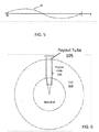
- a coil formed using the example dimensions as seen in Fig. 6 has a straight (radial) payout hole 100 that will not be influenced by the hole taper or density and that can receive a straight payout tube 105.
- the coil 108 formed using this method will be more stable than using prior methods, which tend to increase the number of figure-eights to much higher values in the outer layers.
- a predefined traverse speed offset vs. coil diameter profile can be used to produce a coil with very high spacing between figure-eights for inner windings or layers of the coil and reduced spacing between figure-eights in the outer windings or layers of the coil.
- the profile can be implemented as a lookup table or a functional relationship to facilitate computer implementation.
- a density profile (layer vs speed offset %) may thus be as shown in Table 3, below.
- Table 3 Layer Speed Offset % 1 8 2 7.4 3 6.9 4 5.7 5 5.1 6 4.6 7 4 8 3.4 9 2.9 10 2.3 11 2.2 12 2.1 13 2.1 14 2.0
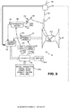
- controller 30 can track the displacement of spindle 31 and traverse 32 with encoders 33 and 34, respectively, although other devices, such as potentiometers or resolvers, can be used.
- the necessary upper and lower speed offsets e.g., ADVANCES
- the ADVANCES are entered either with an input device 30A such as thumb-wheel switches, a keypad, computer keyboard, an internally stored data base, or downloaded from a database through serial communication (none shown in FIG. 3 ).
- the ADVANCES are calculated from the diameter of the filamentary material 29, the diameter of the mandrel 31A, and the distance of the traverse 32 from the surface of spindle 31.
- Various parameters of the winding process are displayed via a display 30B.
- the controller 30 reads the position of the spindle 31 and traverse 32 and provides a reference signal 41 to the traverse motor 38 via the traverse drive 40 that results in an ADVANCE to the traverse 32.
- the controller 30 switches the sense of the ADVANCE (plus or minus) when it is time to make the payout hole in the winding.
- the aforementioned operations are known to those skilled in the winding art.
- the spindle motor 37 is controlled by spindle drive 42 by a reference signal 43 from the controller 30 in a manner known to the winding art.
- the traverse 32 may be driven with a crank arm 35 and connecting rod 36.
- a crank arm 35 and connecting rod 36 When such an arrangement of a crank arm 35 and connecting rod 36 is driven at a constant RPM (of the crank arm 35) by the traverse motor 38 and cam box 39, distortion may be created in the motion of the traverse 32.
- the cam box 39 may use an arrangement of cams to remove such distortion.
- the controller 30 receives input of the respective position of the traverse motor 38 and the spindle motor 37 via encoders 34 and 33, respectively, through counter circuitry 44. Winding a coil with the programmed density may be carried out by either programming the controller 30 to solve equation (1) above, or to provide a "look-up" table (such as Table 3) in the computer so that the necessary ADVANCES can be provided to the traverse motor 38 and/or the spindle motor 37.
- the winding machine 10 described herein should not be considered limited to the specific physical layout described. Some practical considerations for features of the winding machine are as follows. Mechanical cams may provide the most speed. Dual and single belt traverses may also be utilized. Electronic cams may provide a certain amount of flexibility, but may have speed limitations. DC motors can be used as well as AC motors, steppers or servos. The traverse 32, if driven by a mechanical cam, can be driven with a standard rotary motor (DC, AC, stepper, servo). Electronic cams can use a servo motor or linear motor.
- the controller may include a computer system.
- the computer system may also include a computer processor (e.g., a microprocessor, microcontroller, digital signal processor, or general purpose computer) for executing any of the methods and processes described above.
- a computer processor e.g., a microprocessor, microcontroller, digital signal processor, or general purpose computer
- the computer system may further include a memory such as a semiconductor memory device (e.g., a RAM, ROM, PROM, EEPROM, or Flash-Programmable RAM), a magnetic memory device (e.g., a diskette or fixed disk), an optical memory device (e.g., a CD-ROM), a PC card (e.g., PCMCIA card), or other memory device.
- a semiconductor memory device e.g., a RAM, ROM, PROM, EEPROM, or Flash-Programmable RAM
- a magnetic memory device e.g., a diskette or fixed disk
- an optical memory device e.g., a CD-ROM
- PC card e.g., PCMCIA card
- the computer program logic may be embodied in various forms, including a source code form or a computer executable form.
- Source code may include a series of computer program instructions in a variety of programming languages (e.g., an object code, an assembly language, or a high-level language such as C, C++, or JAVA).
- Such computer instructions can be stored in a non-transitory computer readable medium (e.g., memory) and executed by the computer processor.
- the computer instructions may be distributed in any form as a removable storage medium with accompanying printed or electronic documentation (e.g., shrink wrapped software), preloaded with a computer system (e.g., on system ROM or fixed disk), or distributed from a server or electronic bulletin board over a communication system (e.g., the Internet or World Wide Web).
- a removable storage medium with accompanying printed or electronic documentation (e.g., shrink wrapped software), preloaded with a computer system (e.g., on system ROM or fixed disk), or distributed from a server or electronic bulletin board over a communication system (e.g., the Internet or World Wide Web).
- a communication system e.g., the Internet or World Wide Web
- the controller may include discrete electronic components coupled to a printed circuit board, integrated circuitry (e.g., Application Specific Integrated Circuits (ASIC)), and/or programmable logic devices (e.g., a Field Programmable Gate Arrays (FPGA)). Any of the methods and processes described above can be implemented using such logic devices.
- integrated circuitry e.g., Application Specific Integrated Circuits (ASIC)
- programmable logic devices e.g., a Field Programmable Gate Arrays (FPGA)
Landscapes
- Engineering & Computer Science (AREA)
- Microelectronics & Electronic Packaging (AREA)
- Winding, Rewinding, Material Storage Devices (AREA)
- Moulding By Coating Moulds (AREA)
- Winding Filamentary Materials (AREA)
- Filamentary Materials, Packages, And Safety Devices Therefor (AREA)
- Manufacture Of Motors, Generators (AREA)
Claims (13)
- Vorrichtung (10) zum Aufwickeln von fadenförmigem Material (29), die Folgendes umfasst:einen Dorn (31A), der um eine Spindeldrehachse (31) drehbar ist, und eine Traverse (32), die sich in einem Abstand in Bezug auf die genannte Spindelachse (31) hin- und herbewegt, um das genannte fadenförmige Material (29) in einer Achterspulenkonfiguration (35) zu wickeln, wobei sich ein Ausgangsloch radial von der inneren zur äußeren Windung der genannten Spule (35) erstreckt;ein Messgerät zum Messen des Durchmessers der genannten Spule, während sie um den genannten Dorn (31A) gewickelt wird, wobei das genannte Messgerät eine Durchmesserbestimmungseinheit zum Bestimmen des Durchmessers der Spule (35) umfasst; undeine Steuerung (30) zum Steuern der Hin- und Herbewegung der genannten Traverse (32) in Bezug auf die Drehung des genannten Dorns (31A) auf der Basis des gemessenen Durchmessers der genannten Spule, um das genannte fadenförmige Material (29) auf den genannten Dorn (31A) in der genannten Spule mit einer Achterkonfiguration zu wickeln, um das genannte radiale Ausgangsloch mit einem konstanten Durchmesser zu bilden,dadurch gekennzeichnet, dass das genannte Messgerät Folgendes umfasst:einen ersten Sensor (24), konfiguriert zum Messen einer Länge von um den genannten Dorn (31A) gewickeltem fadenförmigem Material (L), wobei der genannte erste Sensor einen Encoder (24) enthält, der zum Erzeugen einer Reihe von Impulsen entsprechend der Länge von um den genannten Dorn (31A) gewickeltem fadenförmigem Material konfiguriert ist; undeinen zweiten Sensor (33), konfiguriert zum Messen einer Winkelverschiebung (A) des genannten Dorns (31A) während des Wickelns der Länge an fadenförmigem Material um den genannten Dorn (31A), wobei der genannte zweite Sensor einen Encoder (33) enthält, der zum Erzeugen einer Reihe von Impulsen entsprechend der Winkelverschiebung des genannten Dorns (31A) konfiguriert ist,wobei die Durchmesserbestimmungseinheit zum Bestimmen des Durchmessers (D) der Spule (35) auf der Basis der Menge an von dem genannten zweiten Sensor (33) erzeugten Impulsen zwischen zwei von dem genannten ersten Sensor (24) erzeugten aufeinanderfolgenden Impulsen konfiguriert ist.
- Vorrichtung nach Anspruch 1, wobei:
die Durchmesserbestimmungseinheit zum Bestimmen des Durchmessers (D) der Spule anhand der Gleichung D = (L/A) ·(360/π) konfiguriert ist, wobei L die Länge an um den genannten Dorn (31A) gewickeltem fadenförmigem Material über einen Zeitraum ist und A die Winkelverschiebung des genannten Dorns (31A) über den Zeitraum ist. - Vorrichtung nach Anspruch 1 oder Anspruch 2, wobei:
die Anzahl an von dem genannten zweiten Sensor (33) erzeugten Impulsen ein laufender Mittelwert der Gradzahl ist, um die sich die Länge an fadenförmigem Material (L) zwischen den zwei von dem genannten ersten Sensor (24) erzeugten aufeinanderfolgenden Impulsen verschiebt. - Vorrichtung nach einem vorherigen Anspruch, wobei:
die genannte Steuerung (30) zum Steuern der Traverse (32) zum Wickeln des genannten fadenförmigen Materials (29) auf den genannten Dorn (31A) in der genannten Spule (35) mit einer Achterkonfiguration und zum Bilden des genannten radialen Ausgangslochs mit einer geraden Konfiguration konfiguriert ist. - Vorrichtung nach einem vorherigen Anspruch, wobei:
die genannte Steuerung (30) zum Steuern der Traverse (32) konfiguriert ist, so dass die Anzahl von Achten in jeder Lage der Spule (35) von einer inneren Lage der Spule zu einer äußeren Lage der Spule zunimmt. - Vorrichtung nach Anspruch 5, wobei:
die Anzahl von Achten in jeder Lage von der inneren zur äußeren Lage der Spule (35) linear zunimmt. - Vorrichtung nach Anspruch 5, wobei:
die Anzahl von Achten in jeder Lage von der inneren zur äußeren Lage der Spule (35) nichtlinear zunimmt. - Verfahren zum Wickeln von fadenförmigem Material (29) auf einen Dorn (31A), der um eine Spindeldrehachse (31) drehbar ist, und eine Traverse (32), die sich in einem Abstand in Bezug auf die genannte Spindelachse (31) hin- und herbewegt, um das genannte fadenförmige Material (29) in einer Achterspulenkonfiguration (35) mit einem radialen Ausgangsloch zu wickeln, das sich radial von der inneren zur äußeren Windung der genannten Spule (35) erstreckt, das Folgendes beinhaltet:Steuern der Drehung des genannten Dorns (31A) um die genannte Spindeldrehachse (31), um fadenförmiges Material (29) um den genannten Dorn (31A) zu wickeln;Messen des Durchmessers (D) der Spule (35), während das fadenförmige Material (29) um den genannten Dorn gewickelt wird, wobei das genannte Messen Folgendes beinhaltet:Messen einer Länge an fadenförmigem Material (L), das über einen Zeitraum um den genannten Dorn (31A) gewickelt wird, mittels eines ersten Sensors (24), wobei der genannte erste Sensor einen Encoder (24) enthält, der zum Erzeugen einer Reihe von Impulsen entsprechend der Länge an um den genannten Dorn (31A) gewickeltem fadenförmigem Material konfiguriert ist; undMessen einer Winkelverschiebung (A) des genannten Dorns (31A) über den Zeitraum mittels eines zweiten Sensors (33), wobei der genannte zweite Sensor einen Encoder (33) enthält, der zum Erzeugen einer Reihe von Impulsen entsprechend der Winkelverschiebung des genannten Dorns (31A) konfiguriert ist; undBestimmen des Durchmessers (D) der Spule auf der Basis der Anzahl von Impulsen, die von dem genannten zweiten Sensor (33) zwischen zwei von dem genannten ersten Sensor (24) erzeugten aufeinanderfolgenden Impulsen erzeugt werden; undSteuern, auf der Basis der Messung des genannten Durchmessers, der Hin- und Herbewegung der genannten Traverse (32) in Bezug auf die Drehung des genannten Dorns (31A), um das genannte fadenförmige Material (29) auf den genannten Dorn (31A) zu wickeln, um das genannte radiale Ausgangsloch mit einem konstanten Durchmesser zu bilden.
- Verfahren nach Anspruch 8, wobei das Bestimmen des Durchmessers der Spule das Anwenden der Gleichung D = (L/A) · (360/π) beinhaltet.
- Verfahren nach Anspruch 8 oder Anspruch 9, wobei:
das genannte Steuern der Hin- und Herbewegung der genannten Traverse (32) das Aufwickeln des genannten fadenförmigen Materials (29) auf den genannten Dorn (31A) in der genannten Spule mit einer Achterkonfiguration (35) beinhaltet, um das genannte radiale Ausgangsloch mit einer geraden Konfiguration zu bilden. - Verfahren nach Anspruch 8 oder Anspruch 9, wobei:
das genannte Steuern der Hin- und Herbewegung der genannten Traverse (32) das Wickeln des genannten fadenförmigen Materials (29) auf den genannten Dorn (31A) in der genannten Spule mit einer Achterkonfiguration (35) beinhaltet, so dass die Anzahl von Achten in jeder Lage der Spule (35) von einer inneren Lage zu einer äußeren Lage der Spule (35) zunimmt. - Verfahren nach Anspruch 11, wobei:
die Anzahl von Achten in jeder Lage von der inneren zur äußeren Lage der Spule (35) linear zunimmt. - Verfahren nach Anspruch 11, wobei:
die Anzahl von Achten in jeder Lage von der inneren zur äußeren Lage der Spule (35) nichtlinear zunimmt.
Priority Applications (2)
| Application Number | Priority Date | Filing Date | Title |
|---|---|---|---|
| SI201830417T SI3609825T1 (sl) | 2017-05-19 | 2018-05-17 | Naprava in postopek za navijanje tuljave |
| PL18802962T PL3609825T3 (pl) | 2017-05-19 | 2018-05-17 | Urządzenie i sposób nawijania cewki |
Applications Claiming Priority (2)
| Application Number | Priority Date | Filing Date | Title |
|---|---|---|---|
| US15/600,034 US10207890B2 (en) | 2017-05-19 | 2017-05-19 | Apparatus and method for winding coil |
| PCT/US2018/033078 WO2018213520A1 (en) | 2017-05-19 | 2018-05-17 | Apparatus and method for winding coil |
Publications (3)
| Publication Number | Publication Date |
|---|---|
| EP3609825A1 EP3609825A1 (de) | 2020-02-19 |
| EP3609825A4 EP3609825A4 (de) | 2020-06-10 |
| EP3609825B1 true EP3609825B1 (de) | 2021-07-07 |
Family
ID=64270481
Family Applications (1)
| Application Number | Title | Priority Date | Filing Date |
|---|---|---|---|
| EP18802962.3A Active EP3609825B1 (de) | 2017-05-19 | 2018-05-17 | Vorrichtung und verfahren zum aufwickeln von spulen |
Country Status (13)
| Country | Link |
|---|---|
| US (1) | US10207890B2 (de) |
| EP (1) | EP3609825B1 (de) |
| JP (1) | JP6777828B2 (de) |
| KR (1) | KR102088154B1 (de) |
| CN (1) | CN110709342B (de) |
| CA (1) | CA3062627C (de) |
| HU (1) | HUE056310T2 (de) |
| MX (1) | MX2019013791A (de) |
| PL (1) | PL3609825T3 (de) |
| PT (1) | PT3609825T (de) |
| SI (1) | SI3609825T1 (de) |
| TW (1) | TWI791523B (de) |
| WO (1) | WO2018213520A1 (de) |
Families Citing this family (6)
| Publication number | Priority date | Publication date | Assignee | Title |
|---|---|---|---|---|
| US10815097B2 (en) * | 2019-03-13 | 2020-10-27 | Reelex Packaging Solutions, Inc. | Payout tubes |
| ES2784920B2 (es) * | 2020-02-10 | 2021-05-11 | Twistperfect S L | Maquina y proceso de desenrollado y enrollado de hilo a una velocidad superior a 1m/s |
| CN112760731A (zh) * | 2020-12-29 | 2021-05-07 | 广州美优科技有限公司 | 一种纤维纺织智能制造设备用卷绕头装置 |
| CN114873364B (zh) * | 2021-03-30 | 2024-08-09 | 福建迈可博电子科技集团股份有限公司 | 一种保证电缆绕制平整度的电缆盘线机及其控制方法 |
| CN114426229B (zh) * | 2022-01-26 | 2023-11-24 | 北京三一智造科技有限公司 | 双轮铣泥浆管定位方法、装置、设备及作业机械 |
| CN114717741B (zh) * | 2022-04-28 | 2023-03-28 | 南京航空航天大学 | 一种三维编织机的携纱器上的自动分纱系统及方法 |
Family Cites Families (34)
| Publication number | Priority date | Publication date | Assignee | Title |
|---|---|---|---|---|
| US2634922A (en) | 1949-07-28 | 1953-04-14 | Jr Walter P Taylor | Package |
| US2767938A (en) | 1953-03-26 | 1956-10-23 | Jr Walter P Taylor | Winding flexible material |
| US3061238A (en) | 1957-08-14 | 1962-10-30 | James W Newman | Winding flexible material |
| US3178130A (en) | 1962-10-26 | 1965-04-13 | Jr Walter P Taylor | Winding flexible material |
| US3655140A (en) | 1970-03-02 | 1972-04-11 | Windings Inc | Machine for winding flexible material |
| US3747861A (en) | 1971-09-15 | 1973-07-24 | Windings Inc | Apparatus and method for winding flexible material for twistless payout through a straight radial opening |
| JPS6031733B2 (ja) | 1973-07-06 | 1985-07-24 | 株式会社片岡機械製作所 | 巻取張力制御装置 |
| US3898436A (en) | 1974-03-22 | 1975-08-05 | Armco Steel Corp | Coil diameter control system |
| US4057203A (en) | 1976-05-14 | 1977-11-08 | Windings, Inc. | Package of flexible material with oval payout tube |
| US4057204A (en) | 1976-05-19 | 1977-11-08 | Windings, Inc. | Tube for inner end feedout of flexible material and package utilizing the same |
| US4085902A (en) | 1976-05-28 | 1978-04-25 | Windings, Inc. | Straight hole formation with moving guide path |
| US4373687A (en) | 1981-04-01 | 1983-02-15 | Container Corporation Of America | Dispensing container |
| US4406419A (en) | 1981-05-08 | 1983-09-27 | Windings, Inc. | Method and apparatus for winding flexible material |
| US4523723A (en) | 1983-09-14 | 1985-06-18 | Windings, Inc. | Winding flexible material with layer shifting |
| GB8614605D0 (en) | 1986-06-16 | 1986-07-23 | Mackie & Sons Ltd J | Yarn winding machines |
| JPH01222421A (ja) * | 1988-03-01 | 1989-09-05 | Toko Inc | 巻線装置とその装置による巻線方法 |
| US4920274A (en) | 1989-04-03 | 1990-04-24 | Ppg Industries, Inc. | Metering apparatus and method for the measurement of a fixed length of continuous yarn or strand |
| US5023820A (en) | 1989-05-10 | 1991-06-11 | Beloit Corporation | System for monitoring roll density |
| US5150789A (en) | 1991-01-31 | 1992-09-29 | At&T Bell Laboratories | Package of elongated strand material and carton blank thereof |
| US5150852A (en) | 1991-11-21 | 1992-09-29 | At&T Bell Laboratories | Payout tube with improved locking means |
| IT1257931B (it) * | 1992-12-14 | 1996-02-19 | Ceat Cavi Ind Srl | Sistema di controllo per una macchina bobinatrice per cavi elettrici e simili, comprendente un sistema di visione artificiale per il controllo della stratificazione delle spire, e procedimento di controllo di tale macchina |
| CN1102625A (zh) * | 1993-06-25 | 1995-05-17 | Savio纺织机械责任有限公司 | 借助驱动辊与导纱器将绕纱分布到筒管上的方法与设备 |
| US5499775A (en) | 1993-07-26 | 1996-03-19 | Communication Cable, Inc. | Winding machine with programmable traverse control |
| US5470026A (en) | 1993-10-01 | 1995-11-28 | Windings, Inc. | Uniform width payout hole |
| US5678778A (en) | 1995-03-24 | 1997-10-21 | Windings, Inc. | High speed, dual head, on-line winding apparatus |
| DE19625512A1 (de) | 1996-06-26 | 1998-01-15 | Schlafhorst & Co W | Verfahren und Vorrichtung zum Bestimmen des Durchmessers einer Kreuzspule |
| US5979812A (en) | 1998-04-21 | 1999-11-09 | Windings, Inc. | Coil with large payout hole and tube for kinkless payout |
| US7249726B2 (en) | 2004-09-27 | 2007-07-31 | Reelex Packaging Solutions, Inc. | Programmed density of wound coils |
| ITMI20051929A1 (it) * | 2005-10-13 | 2007-04-14 | Savio Macchine Tessili Spa | Dispositivo e procedimento per la misurazione di precisioni della metratura del filo avvolto su una rocca |
| US8079539B2 (en) | 2010-01-26 | 2011-12-20 | Delta Electronics, Inc. | Built-in module for inverter and having tension control with integrated tension and velocity closed loops |
| DE102010012263B3 (de) * | 2010-03-22 | 2011-07-28 | Wafios AG, 72764 | Vorrichtung zum Steuern des Antriebs einer Haspel |
| DE102011000590B3 (de) * | 2011-02-09 | 2012-05-24 | Georg Sahm Gmbh & Co. Kg | Spulmaschine |
| JP2012250810A (ja) * | 2011-06-02 | 2012-12-20 | Murata Machinery Ltd | 糸巻取装置 |
| US9731931B2 (en) | 2014-09-23 | 2017-08-15 | Reelex Packaging Solutions, Inc. | Apparatus and methods for winding coil |
-
2017
- 2017-05-19 US US15/600,034 patent/US10207890B2/en active Active
-
2018
- 2018-05-17 EP EP18802962.3A patent/EP3609825B1/de active Active
- 2018-05-17 HU HUE18802962A patent/HUE056310T2/hu unknown
- 2018-05-17 KR KR1020197037526A patent/KR102088154B1/ko active Active
- 2018-05-17 CN CN201880033199.4A patent/CN110709342B/zh active Active
- 2018-05-17 PT PT188029623T patent/PT3609825T/pt unknown
- 2018-05-17 CA CA3062627A patent/CA3062627C/en active Active
- 2018-05-17 MX MX2019013791A patent/MX2019013791A/es unknown
- 2018-05-17 PL PL18802962T patent/PL3609825T3/pl unknown
- 2018-05-17 SI SI201830417T patent/SI3609825T1/sl unknown
- 2018-05-17 WO PCT/US2018/033078 patent/WO2018213520A1/en not_active Ceased
- 2018-05-17 JP JP2019564086A patent/JP6777828B2/ja active Active
- 2018-05-18 TW TW107117008A patent/TWI791523B/zh active
Non-Patent Citations (1)
| Title |
|---|
| None * |
Also Published As
| Publication number | Publication date |
|---|---|
| US20180334352A1 (en) | 2018-11-22 |
| CN110709342A (zh) | 2020-01-17 |
| BR112019023701A2 (pt) | 2020-05-26 |
| US10207890B2 (en) | 2019-02-19 |
| KR20200003928A (ko) | 2020-01-10 |
| JP2020520867A (ja) | 2020-07-16 |
| EP3609825A4 (de) | 2020-06-10 |
| KR102088154B1 (ko) | 2020-05-15 |
| PT3609825T (pt) | 2021-10-15 |
| EP3609825A1 (de) | 2020-02-19 |
| WO2018213520A1 (en) | 2018-11-22 |
| HUE056310T2 (hu) | 2022-02-28 |
| CN110709342B (zh) | 2020-12-22 |
| MX2019013791A (es) | 2020-02-12 |
| TW201900538A (zh) | 2019-01-01 |
| PL3609825T3 (pl) | 2021-12-27 |
| TWI791523B (zh) | 2023-02-11 |
| SI3609825T1 (sl) | 2022-01-31 |
| CA3062627A1 (en) | 2018-11-22 |
| CA3062627C (en) | 2020-09-08 |
| JP6777828B2 (ja) | 2020-10-28 |
Similar Documents
| Publication | Publication Date | Title |
|---|---|---|
| EP3609825B1 (de) | Vorrichtung und verfahren zum aufwickeln von spulen | |
| EP0999992B1 (de) | Verfahren und changiereinrichtung zum verlegen eines fadens | |
| EP0646536B1 (de) | Öffnung gleichbleibender Breite zum Abwickeln | |
| DE10300106B4 (de) | Verfahren zur Steuerung des Antriebsmotors einer Traversierführung | |
| CN113526232B (zh) | 用于在卷绕筒管时对纱线高精度地垫放纱线的方法 | |
| EP1640306A1 (de) | Programmierte Dichte von gewickelten Spulen | |
| US9540208B2 (en) | Apparatus and methods for winding coil using traverse with rotating element | |
| US4485978A (en) | Method and apparatus for winding strand upon spools having tapered end flanges | |
| US4725010A (en) | Control apparatus and method | |
| JPH0790742A (ja) | ワープビーム駆動装置 | |
| US20010042808A1 (en) | Device for traversing a flexible linear product for spooling | |
| EP1222133B1 (de) | Verfahren und vorrichtung zum aufwickeln eines fadens auf eine spule | |
| US4738406A (en) | Control apparatus and method | |
| USRE33240E (en) | Control apparatus and method | |
| US6402076B1 (en) | Method of controlling speed and rotation counts of a spindle of an exact sheet-count metered winder | |
| BR112019023701B1 (pt) | Aparelho e método para enrolar material filamentoso | |
| JPH04106063A (ja) | 尾端定位置停止制御装置 | |
| HK40055709A (en) | Method for laying a yarn with high-precision during winding of a bobbin | |
| MXPA94007654A (es) | Orificio de alargamiento gradual de ancho uniforme. | |
| HK40055709B (en) | Method for laying a yarn with high-precision during winding of a bobbin | |
| JPS6194975A (ja) | 巻線機におけるトラバース速度制御装置 | |
| UA62698A (en) | Method for winding hoop into bundles | |
| HK1120774A (en) | Programmed density of wound coils |
Legal Events
| Date | Code | Title | Description |
|---|---|---|---|
| STAA | Information on the status of an ep patent application or granted ep patent |
Free format text: STATUS: THE INTERNATIONAL PUBLICATION HAS BEEN MADE |
|
| PUAI | Public reference made under article 153(3) epc to a published international application that has entered the european phase |
Free format text: ORIGINAL CODE: 0009012 |
|
| STAA | Information on the status of an ep patent application or granted ep patent |
Free format text: STATUS: REQUEST FOR EXAMINATION WAS MADE |
|
| 17P | Request for examination filed |
Effective date: 20191111 |
|
| AK | Designated contracting states |
Kind code of ref document: A1 Designated state(s): AL AT BE BG CH CY CZ DE DK EE ES FI FR GB GR HR HU IE IS IT LI LT LU LV MC MK MT NL NO PL PT RO RS SE SI SK SM TR |
|
| AX | Request for extension of the european patent |
Extension state: BA ME |
|
| A4 | Supplementary search report drawn up and despatched |
Effective date: 20200512 |
|
| RIC1 | Information provided on ipc code assigned before grant |
Ipc: G01B 11/10 20060101ALI20200506BHEP Ipc: B65H 18/08 20060101ALI20200506BHEP Ipc: G01B 11/00 20060101ALI20200506BHEP Ipc: G01B 11/08 20060101ALI20200506BHEP Ipc: B65H 54/00 20060101ALI20200506BHEP Ipc: B65H 18/00 20060101AFI20200506BHEP Ipc: B65H 55/04 20060101ALI20200506BHEP Ipc: B65H 54/02 20060101ALI20200506BHEP Ipc: B65H 54/28 20060101ALI20200506BHEP Ipc: B65H 61/00 20060101ALI20200506BHEP Ipc: B65H 54/06 20060101ALI20200506BHEP |
|
| DAV | Request for validation of the european patent (deleted) | ||
| DAX | Request for extension of the european patent (deleted) | ||
| STAA | Information on the status of an ep patent application or granted ep patent |
Free format text: STATUS: EXAMINATION IS IN PROGRESS |
|
| 17Q | First examination report despatched |
Effective date: 20201006 |
|
| GRAP | Despatch of communication of intention to grant a patent |
Free format text: ORIGINAL CODE: EPIDOSNIGR1 |
|
| STAA | Information on the status of an ep patent application or granted ep patent |
Free format text: STATUS: GRANT OF PATENT IS INTENDED |
|
| INTG | Intention to grant announced |
Effective date: 20210215 |
|
| GRAS | Grant fee paid |
Free format text: ORIGINAL CODE: EPIDOSNIGR3 |
|
| GRAA | (expected) grant |
Free format text: ORIGINAL CODE: 0009210 |
|
| STAA | Information on the status of an ep patent application or granted ep patent |
Free format text: STATUS: THE PATENT HAS BEEN GRANTED |
|
| AK | Designated contracting states |
Kind code of ref document: B1 Designated state(s): AL AT BE BG CH CY CZ DE DK EE ES FI FR GB GR HR HU IE IS IT LI LT LU LV MC MK MT NL NO PL PT RO RS SE SI SK SM TR |
|
| REG | Reference to a national code |
Ref country code: GB Ref legal event code: FG4D |
|
| REG | Reference to a national code |
Ref country code: AT Ref legal event code: REF Ref document number: 1408417 Country of ref document: AT Kind code of ref document: T Effective date: 20210715 |
|
| REG | Reference to a national code |
Ref country code: DE Ref legal event code: R096 Ref document number: 602018019872 Country of ref document: DE |
|
| REG | Reference to a national code |
Ref country code: IE Ref legal event code: FG4D |
|
| REG | Reference to a national code |
Ref country code: SE Ref legal event code: TRGR |
|
| REG | Reference to a national code |
Ref country code: PT Ref legal event code: SC4A Ref document number: 3609825 Country of ref document: PT Date of ref document: 20211015 Kind code of ref document: T Free format text: AVAILABILITY OF NATIONAL TRANSLATION Effective date: 20211006 |
|
| REG | Reference to a national code |
Ref country code: NL Ref legal event code: FP |
|
| REG | Reference to a national code |
Ref country code: LT Ref legal event code: MG9D |
|
| REG | Reference to a national code |
Ref country code: SK Ref legal event code: T3 Ref document number: E 38184 Country of ref document: SK |
|
| REG | Reference to a national code |
Ref country code: GR Ref legal event code: EP Ref document number: 20210402656 Country of ref document: GR Effective date: 20211111 |
|
| REG | Reference to a national code |
Ref country code: AT Ref legal event code: MK05 Ref document number: 1408417 Country of ref document: AT Kind code of ref document: T Effective date: 20210707 |
|
| PG25 | Lapsed in a contracting state [announced via postgrant information from national office to epo] |
Ref country code: HR Free format text: LAPSE BECAUSE OF FAILURE TO SUBMIT A TRANSLATION OF THE DESCRIPTION OR TO PAY THE FEE WITHIN THE PRESCRIBED TIME-LIMIT Effective date: 20210707 Ref country code: FI Free format text: LAPSE BECAUSE OF FAILURE TO SUBMIT A TRANSLATION OF THE DESCRIPTION OR TO PAY THE FEE WITHIN THE PRESCRIBED TIME-LIMIT Effective date: 20210707 Ref country code: ES Free format text: LAPSE BECAUSE OF FAILURE TO SUBMIT A TRANSLATION OF THE DESCRIPTION OR TO PAY THE FEE WITHIN THE PRESCRIBED TIME-LIMIT Effective date: 20210707 Ref country code: RS Free format text: LAPSE BECAUSE OF FAILURE TO SUBMIT A TRANSLATION OF THE DESCRIPTION OR TO PAY THE FEE WITHIN THE PRESCRIBED TIME-LIMIT Effective date: 20210707 Ref country code: LT Free format text: LAPSE BECAUSE OF FAILURE TO SUBMIT A TRANSLATION OF THE DESCRIPTION OR TO PAY THE FEE WITHIN THE PRESCRIBED TIME-LIMIT Effective date: 20210707 Ref country code: BG Free format text: LAPSE BECAUSE OF FAILURE TO SUBMIT A TRANSLATION OF THE DESCRIPTION OR TO PAY THE FEE WITHIN THE PRESCRIBED TIME-LIMIT Effective date: 20211007 Ref country code: AT Free format text: LAPSE BECAUSE OF FAILURE TO SUBMIT A TRANSLATION OF THE DESCRIPTION OR TO PAY THE FEE WITHIN THE PRESCRIBED TIME-LIMIT Effective date: 20210707 Ref country code: NO Free format text: LAPSE BECAUSE OF FAILURE TO SUBMIT A TRANSLATION OF THE DESCRIPTION OR TO PAY THE FEE WITHIN THE PRESCRIBED TIME-LIMIT Effective date: 20211007 |
|
| PG25 | Lapsed in a contracting state [announced via postgrant information from national office to epo] |
Ref country code: LV Free format text: LAPSE BECAUSE OF FAILURE TO SUBMIT A TRANSLATION OF THE DESCRIPTION OR TO PAY THE FEE WITHIN THE PRESCRIBED TIME-LIMIT Effective date: 20210707 |
|
| REG | Reference to a national code |
Ref country code: HU Ref legal event code: AG4A Ref document number: E056310 Country of ref document: HU |
|
| REG | Reference to a national code |
Ref country code: DE Ref legal event code: R097 Ref document number: 602018019872 Country of ref document: DE |
|
| PG25 | Lapsed in a contracting state [announced via postgrant information from national office to epo] |
Ref country code: DK Free format text: LAPSE BECAUSE OF FAILURE TO SUBMIT A TRANSLATION OF THE DESCRIPTION OR TO PAY THE FEE WITHIN THE PRESCRIBED TIME-LIMIT Effective date: 20210707 |
|
| PLBE | No opposition filed within time limit |
Free format text: ORIGINAL CODE: 0009261 |
|
| STAA | Information on the status of an ep patent application or granted ep patent |
Free format text: STATUS: NO OPPOSITION FILED WITHIN TIME LIMIT |
|
| PG25 | Lapsed in a contracting state [announced via postgrant information from national office to epo] |
Ref country code: SM Free format text: LAPSE BECAUSE OF FAILURE TO SUBMIT A TRANSLATION OF THE DESCRIPTION OR TO PAY THE FEE WITHIN THE PRESCRIBED TIME-LIMIT Effective date: 20210707 Ref country code: EE Free format text: LAPSE BECAUSE OF FAILURE TO SUBMIT A TRANSLATION OF THE DESCRIPTION OR TO PAY THE FEE WITHIN THE PRESCRIBED TIME-LIMIT Effective date: 20210707 Ref country code: AL Free format text: LAPSE BECAUSE OF FAILURE TO SUBMIT A TRANSLATION OF THE DESCRIPTION OR TO PAY THE FEE WITHIN THE PRESCRIBED TIME-LIMIT Effective date: 20210707 |
|
| 26N | No opposition filed |
Effective date: 20220408 |
|
| REG | Reference to a national code |
Ref country code: CH Ref legal event code: PL |
|
| REG | Reference to a national code |
Ref country code: BE Ref legal event code: MM Effective date: 20220531 |
|
| PG25 | Lapsed in a contracting state [announced via postgrant information from national office to epo] |
Ref country code: MC Free format text: LAPSE BECAUSE OF FAILURE TO SUBMIT A TRANSLATION OF THE DESCRIPTION OR TO PAY THE FEE WITHIN THE PRESCRIBED TIME-LIMIT Effective date: 20210707 Ref country code: LI Free format text: LAPSE BECAUSE OF NON-PAYMENT OF DUE FEES Effective date: 20220531 Ref country code: CH Free format text: LAPSE BECAUSE OF NON-PAYMENT OF DUE FEES Effective date: 20220531 Ref country code: LU Free format text: LAPSE BECAUSE OF NON-PAYMENT OF DUE FEES Effective date: 20220517 |
|
| PG25 | Lapsed in a contracting state [announced via postgrant information from national office to epo] |
Ref country code: BE Free format text: LAPSE BECAUSE OF NON-PAYMENT OF DUE FEES Effective date: 20220531 |
|
| PG25 | Lapsed in a contracting state [announced via postgrant information from national office to epo] |
Ref country code: MK Free format text: LAPSE BECAUSE OF FAILURE TO SUBMIT A TRANSLATION OF THE DESCRIPTION OR TO PAY THE FEE WITHIN THE PRESCRIBED TIME-LIMIT Effective date: 20210707 Ref country code: CY Free format text: LAPSE BECAUSE OF FAILURE TO SUBMIT A TRANSLATION OF THE DESCRIPTION OR TO PAY THE FEE WITHIN THE PRESCRIBED TIME-LIMIT Effective date: 20210707 |
|
| PG25 | Lapsed in a contracting state [announced via postgrant information from national office to epo] |
Ref country code: MT Free format text: LAPSE BECAUSE OF FAILURE TO SUBMIT A TRANSLATION OF THE DESCRIPTION OR TO PAY THE FEE WITHIN THE PRESCRIBED TIME-LIMIT Effective date: 20210707 |
|
| PGFP | Annual fee paid to national office [announced via postgrant information from national office to epo] |
Ref country code: NL Payment date: 20250414 Year of fee payment: 8 |
|
| PGFP | Annual fee paid to national office [announced via postgrant information from national office to epo] |
Ref country code: PL Payment date: 20250411 Year of fee payment: 8 Ref country code: DE Payment date: 20250423 Year of fee payment: 8 |
|
| PGFP | Annual fee paid to national office [announced via postgrant information from national office to epo] |
Ref country code: GB Payment date: 20250425 Year of fee payment: 8 |
|
| PGFP | Annual fee paid to national office [announced via postgrant information from national office to epo] |
Ref country code: HU Payment date: 20250418 Year of fee payment: 8 |
|
| PGFP | Annual fee paid to national office [announced via postgrant information from national office to epo] |
Ref country code: IT Payment date: 20250415 Year of fee payment: 8 |
|
| PGFP | Annual fee paid to national office [announced via postgrant information from national office to epo] |
Ref country code: PT Payment date: 20250411 Year of fee payment: 8 |
|
| PGFP | Annual fee paid to national office [announced via postgrant information from national office to epo] |
Ref country code: FR Payment date: 20250411 Year of fee payment: 8 |
|
| PGFP | Annual fee paid to national office [announced via postgrant information from national office to epo] |
Ref country code: GR Payment date: 20250414 Year of fee payment: 8 |
|
| PGFP | Annual fee paid to national office [announced via postgrant information from national office to epo] |
Ref country code: RO Payment date: 20250417 Year of fee payment: 8 |
|
| PGFP | Annual fee paid to national office [announced via postgrant information from national office to epo] |
Ref country code: TR Payment date: 20250414 Year of fee payment: 8 Ref country code: SK Payment date: 20250411 Year of fee payment: 8 |
|
| PGFP | Annual fee paid to national office [announced via postgrant information from national office to epo] |
Ref country code: CZ Payment date: 20250411 Year of fee payment: 8 |
|
| PGFP | Annual fee paid to national office [announced via postgrant information from national office to epo] |
Ref country code: IE Payment date: 20250415 Year of fee payment: 8 |
|
| PGFP | Annual fee paid to national office [announced via postgrant information from national office to epo] |
Ref country code: SE Payment date: 20250415 Year of fee payment: 8 Ref country code: SI Payment date: 20250415 Year of fee payment: 8 |