EP3610073B1 - Abdeckung - Google Patents
Abdeckung Download PDFInfo
- Publication number
- EP3610073B1 EP3610073B1 EP18719633.2A EP18719633A EP3610073B1 EP 3610073 B1 EP3610073 B1 EP 3610073B1 EP 18719633 A EP18719633 A EP 18719633A EP 3610073 B1 EP3610073 B1 EP 3610073B1
- Authority
- EP
- European Patent Office
- Prior art keywords
- cover
- main section
- cover according
- recesses
- reinforcement members
- Prior art date
- Legal status (The legal status is an assumption and is not a legal conclusion. Google has not performed a legal analysis and makes no representation as to the accuracy of the status listed.)
- Active
Links
Images

Classifications
-
- E—FIXED CONSTRUCTIONS
- E02—HYDRAULIC ENGINEERING; FOUNDATIONS; SOIL SHIFTING
- E02D—FOUNDATIONS; EXCAVATIONS; EMBANKMENTS; UNDERGROUND OR UNDERWATER STRUCTURES
- E02D17/00—Excavations; Bordering of excavations; Making embankments
- E02D17/06—Foundation trenches ditches or narrow shafts
- E02D17/10—Covering trenches for foundations
-
- E—FIXED CONSTRUCTIONS
- E01—CONSTRUCTION OF ROADS, RAILWAYS, OR BRIDGES
- E01C—CONSTRUCTION OF, OR SURFACES FOR, ROADS, SPORTS GROUNDS, OR THE LIKE; MACHINES OR AUXILIARY TOOLS FOR CONSTRUCTION OR REPAIR
- E01C9/00—Special pavings; Pavings for special parts of roads or airfields
- E01C9/08—Temporary pavings
- E01C9/086—Temporary pavings made of concrete, wood, bitumen, rubber or synthetic material or a combination thereof
-
- E—FIXED CONSTRUCTIONS
- E01—CONSTRUCTION OF ROADS, RAILWAYS, OR BRIDGES
- E01D—CONSTRUCTION OF BRIDGES, ELEVATED ROADWAYS OR VIADUCTS; ASSEMBLY OF BRIDGES
- E01D15/00—Movable or portable bridges; Floating bridges
- E01D15/12—Portable or sectional bridges
- E01D15/133—Portable or sectional bridges built-up from readily separable standardised sections or elements, e.g. Bailey bridges
Definitions
- This invention relates to a cover intended for use in covering a trench or the like formed in a road surface or footpath surface to allow the continued passage of vehicles or pedestrians along the road or footpath surface.
- covers in covering trenches or the like formed in road surfaces are well known.
- the covers have taken the form of steel sheets positioned over trenches and anchored to the road surface using suitable pins, in use. Whilst such covers function adequately, they have the disadvantage that the covers are relatively heavy and so are inconvenient to handle and transport, for example requiring the use of lifting equipment to position the covers over the trench. Clearly, this is inconvenient.
- a significant level of noise is typically generated.
- An alternative form of cover takes the form of a metal reinforced moulded plastics panel, often formed with rubber or rubber like material flexible end sections.
- Such covers are of lighter weight than the traditional metallic covers and so are easier to handle and transport.
- the design of the covers and choice of materials used can result is the generation of less noise as vehicles pass over the covers.
- US patent application US2013/047351 describes a cover for bridging a channel or excavation etc. comprising spaced ground contacting pads and three or more ribs with lateral stabilising elements extending between adjacent ribs, and an upper surface supported by the ribs.
- Canadian application CA2796153 describes a temporary bridge having a cellular framework of box reinforcement structures.
- a cover comprising main section provided with link means to allow linking of the cover to an adjacent cover, wherein the main section is shaped to include opposing side walls and defines a reinforced plastics material central region in which elongate reinforcement members are provided extending within the side walls, and end regions located to opposite ends of and integrally formed with the central region, characterised in that the elongate reinforcement members are contained within the side walls and stop short of the end regions, and wherein the link means are provided at the end regions.
- the side walls are formed with recesses opening to the underside of the cover, the recesses being located in the end regions.
- Recesses of this type are relatively easy to mould into the main section, and so the manufacturing process used in the formation of the cover may be simplified compared to arrangements in which openings have to be machined into the side walls of the main section after moulding thereof.
- the link means conveniently comprise a connector plate fitted to the main section and projecting from one of the recesses thereof, and a connector pin fitted to the main section adjacent another of the recesses thereof.
- the connector pin of one cover is received within an opening provided in the connector plate of an adjacent cover to link the covers to one another.
- the underside of the recess with which the connector pin is associated is preferably closed by a cover plate, the recess and cover plate together defining an opening into which the connector plate of the adjacent cover is fitted for cooperation with the connector pin.
- the connector plate is preferably arranged such that a part thereof in which the opening is provided is angled upwardly, in use. Conveniently, this is achieved by forming the connector plate in such a manner as to include a mounting part secured, in use, to the main section, and an upwardly angled part in which the opening is formed.
- the cover preferably further comprises additional reinforcement members, the reinforcement members and additional reinforcement members together forming a grid-like arrangement.
- the main section preferably defines a series of downwardly depending ribs, the reinforcement members and additional reinforcement members being located within respective ones of the ribs.
- the main section is preferably provided with an opening whereby a probe associated with a gas sensor can be introduced into a trench over which the cover extends to allow tests to be undertaken without first removing the cover from the trench.
- a retainer arrangement may be provided to resist longitudinal movement of the cover, in use.
- the retainer arrangement conveniently comprises a housing with which a plurality of moveable pins are associated, the pins being movable under the action of gravity between raised and lowered positions, the pins projecting from the underside of the main section when in their lowered positions.
- the main section is formed with mounting formations to allow the housing to be secured thereto such that the housing extends in a substantially horizontal orientation, in use.
- Such an arrangement is advantageous in that even where the profile of the main section is curved along its length, the same length pins may be used throughout the retainer arrangement.
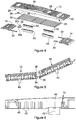
- a cover 10 is illustrated that is intended for use, in conjunction with other similar covers, in covering a trench, opening or cavity or the like formed in a road surface or footpath surface to allow the continued use of the road or footpath by vehicles or pedestrians.
- the primary purpose of the cover 10 is in covering trenches formed in road surface to allow vehicles to pass over the trench. Accordingly, the cover 10 is designed to be of sufficient strength to carry vehicles over the trench.
- the cover 10 is comprises a main section 12 to the ends of which are fitted end ramps 14.
- the main section 12 is of moulded plastics material form shaped to define an upper surface 16 and integral side walls 18.
- the underside of the main section 12 is formed with a series of ribs 20, some of which extend along the length of the main section 12, and some of which extend across the width of the main section 12.
- the main section 12 defines a central, metal reinforced region 22, and integral end regions 24 located to opposite ends of the central region 22.
- the side walls 18 and ribs 20 each contain respective elongate reinforcing members 26, each of which takes the form of a length of steel rod or bar.
- the rods or bars are conveniently welded or otherwise secured to one another in a grid-like configuration before being introduced into a mould and having the plastics material of the main section over moulded onto the reinforcing members 26. It will be appreciated, however, that this represents just one technique by which the main section 12 may be formed, and that other techniques may be used without departing from the scope of the invention.
- the elongate reinforcing members 26 located within the side walls 18 stop short of the end regions 24.
- the reinforcing members 26 located within the ribs 20 stop short of the end regions 24, and so the end regions 24 are not of metal reinforced form.
- the reinforcing members 26 located within the ribs 20 extend into the end regions 24.
- the parts of the sides walls 18 located in the end regions 24 are formed with recesses 28 which open to the underside of the cover.
- the recesses 28 could be machined into the side walls 18 after completion of the moulding process, but are conveniently formed as part of the moulding operation, the mould being shaped in such a manner as to result in the formation of the recesses 28.
- One of the recesses 28 located on each side of the cover 10 has a connector plate 30 associated therewith, the connector plate 30 extending through the recess 28 and including a mounting part 30a located beneath and bolted to (or otherwise secured to) the underside of the main section 12.
- the connector plate 30 further includes a projecting part 30b, angled upwardly relative to the plane of the mounting part 30a and provided with an opening 32.
- the other of the recesses 28 located on each side of the cover 10 has a cover plate 34 mounted adjacent thereto so as to define a closed opening through which a connector pin 36 mounted to the underside of the main section 12 can be accessed.
- the connector plate 30 and connector pin 36 together serve as link means whereby adjacent covers 10 can be connected or linked to one another.
- one of the covers 10 is laid in the desired position and the other is held in an angled configuration to allow the connector plates 30 to be partially inserted into the respective openings defined between the recesses 28 and cover plates 34 to align the openings 32 with the respective connector pins 36.
- the angled one of the covers 10 is then laid down with the result that the connector pins 36 become located within the openings 32, linking the adjacent covers 10 to one another. It will be appreciated that the presence of the cover plates 34 resists lifting of one of the covers 10 relative to the other. It will be appreciated that in this manner, a number of covers 10 can be linked to one another to form an assembly of sufficient width to cover the full length of a trench formed in a road (or other) surface.
- the end ramps 14 are conveniently of a flexible rubber like material which flexes to accommodate bumps, dips or other non-uniformities in the road surface.
- the ramps 14 reduce noise generated as vehicles ride onto and leave the covers 10 and the nature of the materials used in the cover 10 serve to further reduce noise generation and reverberation in use.
- the main section 12 is conveniently formed with one or more openings 38 through which a probe of a gas detector can be inserted, with the cover 10 in position over a trench, to allow gas measurements or tests to be undertaken without the need to first remove the cover 10.
- the retainer means takes the form of a housing 40 secured to the underside of the main section 12, the housing 40 having a series of pins 42 associated therewith.
- Each pin 42 is held captive to the housing 40 and is movable under the action of gravity between a raised position and a lowered position. In use, prior to lowering the cover into position over a trench, all of the pins 42 will adopt their extended, lowered positions, extending beneath the level of the lower edges of the side walls 18.
- the ones of the pins 42 located above the road surface to each side of the trench will be pushed into the housing 40, the remaining pins 42 remaining in their lowered positions. It will be appreciated that the pins 42 in their lowered positions may bear against the side walls of the trench, upon movement of the cover 10 relative to the road surface, limiting or resisting further movement.
- the pins 42 are all of the same length, and in order to function properly, the housing 40 is preferably arranged horizontally, in use. In order to achieve this despite the curved profile of the cover 10 as illustrated, the underside of the main section 12 is conveniently provided with formations 44 upon which the housing 40 is located to hold the housing 40 in a substantially horizontal configuration, in use.
- the cover 10 is advantageous in that the installation of the link means does not require the formation of openings in the side walls of the main section after completion of the moulding thereof, instead the link means being fitted in recesses that can be formed as part of the moulding process.
- the formation of the recesses as part of the moulding process is permitted through arranging for the reinforcing members to stop short of the end sections.
- the presence of reinforcing members in these locations prevents the formation of recesses in these locations, and instead openings are cut above the level of the reinforcing members as a subsequent, time consuming manufacturing step.
- the arrangement of the invention is thus advantageous in that manufacture of the cover is simplified.
- the end sections 24 are not reinforced, it is desirable that in use these sections of the cover overlie the ground surface rather than being located above the trench, the trench preferably being spanned by the reinforced section 22.
- the upper surface 16 is preferably provided with markings identifying which parts of the cover are permitted to safely extend over the trench, in use.
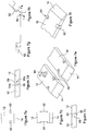
- Figures 7a to 7h illustrate several alternative forms of link means.
- the link means take the form of projections 50 receivable within correspondingly shaped re-entrant recesses 52, the projections 50 and recesses 52 being located at the end sections 24.
- Figure 7c illustrates an arrangement in which, along one side of the cover is formed a lip 54 which can rest upon a ledge 56 projecting from the adjacent cover, bolts 58 or other fasteners being used to secure the lip 54 to the ledge 56.
- the lips 54 and ledges 56 are located at the end sections 24.
- Figure 7d illustrates an alternative configuration in which the lips 54 and ledges 56 includes side walls 54a, 56a which interact to resist separation of the covers.
- Figure 7e illustrates an arrangement in which the link arrangement takes the form of connector plates 60 which can be bolted to the covers, recesses 62 being formed in the end sections 24 to accommodate the connector plates 60.
- Figures 7f to 7h illustrate an arrangement that, in many respects, is similar to that of Figures 1 to 6 but in which the connection plate 62 is located to the top of the cover and is fitted through a slot 64 formed in the end section 24 of the cover.
- the plate 62 is of stepped form rather than being of angled form.
- Figure 7f illustrates part of the cover, Figure 7g illustrating two covers linked to one another, and Figure 7h illustrating the method used to link the covers to one another.
Landscapes
- Engineering & Computer Science (AREA)
- Mining & Mineral Resources (AREA)
- Civil Engineering (AREA)
- Structural Engineering (AREA)
- Life Sciences & Earth Sciences (AREA)
- General Life Sciences & Earth Sciences (AREA)
- Paleontology (AREA)
- General Engineering & Computer Science (AREA)
- Architecture (AREA)
- Details Of Indoor Wiring (AREA)
Claims (15)
- Abdeckung (10), die Folgendes umfasst:eine Hauptsektion (12), die mit Verbindungsmitteln (30, 36) versehen ist, um ein Verbinden der Abdeckung mit einer benachbarten Abdeckung zu ermöglichen, wobeidie Hauptsektion (12) so geformt ist, dass sie gegenüberliegende Seitenwände (18) einschließt, und Folgendes definiert:einen mittleren Bereich (22) aus verstärktem Kunststoffmaterial, in dem längliche Verstärkungselemente (26) bereitgestellt werden, die sich innerhalb der Seitenwände (18) erstrecken, undEndbereiche (24), die zu entgegengesetzten Enden des mittleren Bereichs (22) hin angeordnet und integral mit demselben geformt sind,dadurch gekennzeichnet, dass die länglichen Verstärkungselemente (26) innerhalb der Seitenwände (18) enthalten sind und kurz vor den Endbereichen (24) aufhören, und wobei die Verbindungsmittel (30, 36) an den Endbereichen (24) bereitgestellt werden.
- Abdeckung nach Anspruch 1, wobei die Seitenwände (18) mit Aussparungen (28) geformt sind, die sich zu der Unterseite der Abdeckung (10) öffnen, wobei die Aussparungen in den Endbereichen (24) angeordnet sind.
- Abdeckung nach Anspruch 2, wobei die Verbindungsmittel (30, 36) eine Verbindungsplatte (30), die an der Hauptsektion (12) angepasst ist und von einer der Aussparungen (28) davon vorspringt, und einen Verbindungsstift (36), der an der Hauptsektion (12) angepasst ist, welche angrenzend an eine andere der Aussparungen (28) davon angepasst ist, umfassen.
- Abdeckung nach Anspruch 3, wobei die Unterseite der Aussparung (28), mit der der Verbindungsstift (36) verknüpft ist, durch eine Abdeckplatte (34) verschlossen ist, wobei die Aussparung (28) und die Abdeckplatte (34) zusammen eine Öffnung definieren, in welche die Verbindungsplatte (30) der benachbarten Abdeckung zum Zusammenwirken mit dem Verbindungsstift (36) angepasst ist.
- Abdeckung nach Anspruch 3 oder Anspruch 4, wobei die Verbindungsplatte (30) derart angeordnet ist, dass ein vorspringender Teil davon, bei Anwendung, nach oben abgewinkelt ist.
- Abdeckung nach Anspruch 5, wobei die Verbindungsplatte (30) einen Montageteil (30a), der, bei Anwendung, an der Hauptsektion (12) befestigt ist, und einen nach oben abgewinkelten Teil (30b), in dem eine Öffnung (32) zum Zusammenwirken mit dem Verbindungsstift (36) geformt ist, einschließt.
- Abdeckung nach einem der vorhergehenden Ansprüche, wobei die Abdeckung (10) ferner zusätzliche Verstärkungselemente (26) umfasst, wobei die Verstärkungselemente (26) und die zusätzlichen Verstärkungselemente (26) zusammen eine gitterartige Anordnung bilden.
- Abdeckung nach Anspruch 7, wobei der Hauptbereich eine Reihe von nach unten hängenden Rippen (20) definiert, wobei die Verstärkungselemente (26) und die zusätzlichen Verstärkungselemente (26) innerhalb jeweiliger der Rippen (20) angeordnet sind.
- Abdeckung nach einem der vorhergehenden Ansprüche, wobei flexible Endrampen (14) an den Endbereichen (24) befestigt sind.
- Abdeckung nach einem der vorhergehenden Ansprüche, wobei die Hauptsektion (12) mit einer Öffnung zum Aufnehmen einer Sonde, die mit einem Gassensor verknüpft ist, versehen ist.
- Abdeckung nach einem der vorhergehenden Ansprüche, wobei eine Rückhalteanordnung bereitgestellt wird, um, bei Anwendung, einer Längsbewegung der Abdeckung (10) zu widerstehen.
- Abdeckung nach Anspruch 11, wobei die Rückhalteanordnung ein Gehäuse (40) umfasst, mit dem eine Vielzahl von beweglichen Stiften (42) verknüpft ist, wobei die Stifte (42) unter der Wirkung der Schwerkraft zwischen erhöhten und abgesenkten Positionen beweglich sind, wobei die Stifte (42) von der Unterseite der Hauptsektion (12) vorspringen, wenn sie sich in ihren abgesenkten Positionen befinden, und wahlweise
wobei die Hauptsektion (12) mit Montageformationen geformt ist, um zu ermöglichen, dass das Gehäuse derart daran befestigt wird, dass sich das Gehäuse (40), bei Anwendung, in einer im Wesentlichen horizontalen Ausrichtung erstreckt. - Abdeckung nach einem der vorhergehenden Ansprüche, wobei die Verbindungsmittel die Form von Vorsprüngen (50) annehmen, die innerhalb von entsprechend geformten einspringenden Aussparungen (52) aufgenommen werden können.
- Abdeckung nach einem der vorhergehenden Ansprüche, wobei die Abdeckung (10) mit einer Lippe (54) geformt ist, die auf einer Leiste (56) aufliegen kann, die von der benachbarten Abdeckung vorspringt.
- Abdeckung nach einem der vorhergehenden Ansprüche, wobei die Verbindungsmittel Verbindungsplatten (60) umfassen, die an die Abdeckungen gebolzt werden können, wobei Aussparungen (62) in den Endbereichen (24) geformt sind, um die Verbindungsplatten (60) aufzunehmen.
Applications Claiming Priority (2)
| Application Number | Priority Date | Filing Date | Title |
|---|---|---|---|
| GB1705953.6A GB2561384A (en) | 2017-04-13 | 2017-04-13 | Cover |
| PCT/GB2018/050983 WO2018189552A1 (en) | 2017-04-13 | 2018-04-13 | Cover |
Publications (2)
| Publication Number | Publication Date |
|---|---|
| EP3610073A1 EP3610073A1 (de) | 2020-02-19 |
| EP3610073B1 true EP3610073B1 (de) | 2021-11-10 |
Family
ID=58744531
Family Applications (1)
| Application Number | Title | Priority Date | Filing Date |
|---|---|---|---|
| EP18719633.2A Active EP3610073B1 (de) | 2017-04-13 | 2018-04-13 | Abdeckung |
Country Status (4)
| Country | Link |
|---|---|
| US (1) | US10774496B2 (de) |
| EP (1) | EP3610073B1 (de) |
| GB (1) | GB2561384A (de) |
| WO (1) | WO2018189552A1 (de) |
Family Cites Families (23)
| Publication number | Priority date | Publication date | Assignee | Title |
|---|---|---|---|---|
| US4819910A (en) * | 1988-08-01 | 1989-04-11 | Johnston Paul F | Trailer leveler |
| DK1192322T3 (da) * | 1999-07-02 | 2008-03-31 | Excellent Systems As | Udstyr til lettelse af körestolsbrugerens passage gennem niveauforskelle, særligt over dörtærskler |
| ATE365832T1 (de) | 1999-09-17 | 2007-07-15 | David Vincent Byrne | Grabendeckelelement |
| US6752381B2 (en) * | 2002-02-06 | 2004-06-22 | Tri-Lynx Corporation | Wheel positional restraint device and method for using the same |
| CA2414518C (en) * | 2003-01-03 | 2010-03-30 | Shawn Beamish | Road mats |
| US6993801B2 (en) * | 2003-07-03 | 2006-02-07 | Land Wave Products, Inc. | Variable ramp assemblies and system therefor |
| US7003836B2 (en) * | 2003-12-19 | 2006-02-28 | Cencor Plastics, Inc. | Portable car ramp |
| KR100604251B1 (ko) * | 2004-09-06 | 2006-07-28 | 주식회사 국민씨아이 | 스냅-핏 결합구조를 가진 중공단면의 섬유강화 복합소재교량 바닥판 |
| US7300224B2 (en) * | 2005-10-05 | 2007-11-27 | Slater William B | Support grid platform for supporting vehicles over ecologically sensitive terrain |
| US7674066B2 (en) * | 2005-10-25 | 2010-03-09 | Donald Wehmeyer | Tactile tile product for the visually impaired, method of manufacture and methods of conducting business therewith |
| US7104524B1 (en) * | 2006-02-09 | 2006-09-12 | Davric Corporation, Inc. | Vehicle ramp with chock |
| ES2627203T3 (es) * | 2007-01-24 | 2017-07-27 | Reynolds Presto Products Inc. | Sistema de pavimento poroso portátil y método para montar tal sistema de pavimento |
| US8061929B2 (en) * | 2008-06-06 | 2011-11-22 | Dagesse Paul J | Rig mat system using panels of composite material |
| US7980532B2 (en) * | 2009-04-02 | 2011-07-19 | Valterra Products, Inc. | Vehicle leveling device |
| US8075221B2 (en) * | 2009-11-12 | 2011-12-13 | Hortech, Inc. | Paver assembly |
| US8282311B2 (en) * | 2010-07-23 | 2012-10-09 | Inpress Technologies Inc. | Paving block formed of rubber crumb and a method of manufacturing the same |
| US8336146B1 (en) * | 2011-06-13 | 2012-12-25 | Berbash Khaled M | Forced air heated mat |
| US8382393B1 (en) * | 2011-06-17 | 2013-02-26 | Hb Green Resources, Llc | Temporary roadway for moving heavy equipment on an incline and steep grades including synthetic inter-connectable movable and removable structural mats |
| US20130047351A1 (en) * | 2011-08-31 | 2013-02-28 | Marc Breault | Pipeline crossing bridge |
| CA2796153A1 (en) * | 2012-11-20 | 2014-05-20 | Renn Mill Center Inc. | Temporary bridge |
| US8807865B1 (en) * | 2013-03-15 | 2014-08-19 | Easy Grass, LLC | Light weight load-bearing platform |
| US9771725B2 (en) | 2013-07-15 | 2017-09-26 | John Bradley Matchung | Modular flooring system |
| US8734049B1 (en) * | 2013-11-22 | 2014-05-27 | Barry J. Stiles | One piece water permeable paver |
-
2017
- 2017-04-13 GB GB1705953.6A patent/GB2561384A/en not_active Withdrawn
-
2018
- 2018-04-13 US US16/604,816 patent/US10774496B2/en active Active
- 2018-04-13 EP EP18719633.2A patent/EP3610073B1/de active Active
- 2018-04-13 WO PCT/GB2018/050983 patent/WO2018189552A1/en not_active Ceased
Also Published As
| Publication number | Publication date |
|---|---|
| GB2561384A (en) | 2018-10-17 |
| WO2018189552A1 (en) | 2018-10-18 |
| GB201705953D0 (en) | 2017-05-31 |
| US10774496B2 (en) | 2020-09-15 |
| US20200080271A1 (en) | 2020-03-12 |
| EP3610073A1 (de) | 2020-02-19 |
Similar Documents
| Publication | Publication Date | Title |
|---|---|---|
| US12334720B2 (en) | Structure for attaching grating lid onto resin trough body; trough track; trough track forming method; and grating lid | |
| WO2015191097A1 (en) | Synthetic modular flooring apparatus | |
| EP3830347B1 (de) | Bodenoberflächenzugangsanordnungen | |
| US10774496B2 (en) | Cover | |
| KR100986232B1 (ko) | 다목적 가림블럭 | |
| KR101085213B1 (ko) | 복공판 | |
| JP4315605B2 (ja) | マンホール立て坑内設置の中間ステージ | |
| GB2316428A (en) | Drainage assembly | |
| WO2008007981A1 (en) | Access cover | |
| US5179752A (en) | Cover for trenches | |
| US10508396B2 (en) | Water barrier element | |
| GB2347706A (en) | Drainage channel lid assembly | |
| KR101386945B1 (ko) | 웨지 타입 트렌치 커버 | |
| US12359391B2 (en) | Modular access cover | |
| KR100807660B1 (ko) | 절연성 맨홀구조 | |
| KR100859262B1 (ko) | 보도용 블록 및 이를 구비한 보도용 블록 조립체 | |
| KR101506158B1 (ko) | 맨홀 뚜껑 잠금장치 | |
| KR102478730B1 (ko) | 옹벽용 점검로 구조물 | |
| KR100653924B1 (ko) | 점검구가 설치된 상하수도·전기·통신용 맨홀뚜껑 | |
| HUE029077T2 (en) | Modular system for driving tracks, especially sliding pool roof | |
| KR102541424B1 (ko) | 기능성 맨홀 뚜껑 | |
| KR200425920Y1 (ko) | 조립식 아스콘 복합형 복공판 | |
| KR100669921B1 (ko) | 길이조절이 가능한 측구용 덮개 | |
| CN215830081U (zh) | 一种墙体截面加固结构 | |
| KR20110111208A (ko) | 배수구용 그레이팅 |
Legal Events
| Date | Code | Title | Description |
|---|---|---|---|
| STAA | Information on the status of an ep patent application or granted ep patent |
Free format text: STATUS: UNKNOWN |
|
| STAA | Information on the status of an ep patent application or granted ep patent |
Free format text: STATUS: THE INTERNATIONAL PUBLICATION HAS BEEN MADE |
|
| PUAI | Public reference made under article 153(3) epc to a published international application that has entered the european phase |
Free format text: ORIGINAL CODE: 0009012 |
|
| STAA | Information on the status of an ep patent application or granted ep patent |
Free format text: STATUS: REQUEST FOR EXAMINATION WAS MADE |
|
| 17P | Request for examination filed |
Effective date: 20191011 |
|
| AK | Designated contracting states |
Kind code of ref document: A1 Designated state(s): AL AT BE BG CH CY CZ DE DK EE ES FI FR GB GR HR HU IE IS IT LI LT LU LV MC MK MT NL NO PL PT RO RS SE SI SK SM TR |
|
| AX | Request for extension of the european patent |
Extension state: BA ME |
|
| DAV | Request for validation of the european patent (deleted) | ||
| DAX | Request for extension of the european patent (deleted) | ||
| GRAP | Despatch of communication of intention to grant a patent |
Free format text: ORIGINAL CODE: EPIDOSNIGR1 |
|
| STAA | Information on the status of an ep patent application or granted ep patent |
Free format text: STATUS: GRANT OF PATENT IS INTENDED |
|
| INTG | Intention to grant announced |
Effective date: 20210526 |
|
| RIN1 | Information on inventor provided before grant (corrected) |
Inventor name: WHITELEY, CHRISTOPHER JAMES |
|
| GRAS | Grant fee paid |
Free format text: ORIGINAL CODE: EPIDOSNIGR3 |
|
| GRAA | (expected) grant |
Free format text: ORIGINAL CODE: 0009210 |
|
| STAA | Information on the status of an ep patent application or granted ep patent |
Free format text: STATUS: THE PATENT HAS BEEN GRANTED |
|
| AK | Designated contracting states |
Kind code of ref document: B1 Designated state(s): AL AT BE BG CH CY CZ DE DK EE ES FI FR GB GR HR HU IE IS IT LI LT LU LV MC MK MT NL NO PL PT RO RS SE SI SK SM TR |
|
| REG | Reference to a national code |
Ref country code: GB Ref legal event code: FG4D |
|
| REG | Reference to a national code |
Ref country code: AT Ref legal event code: REF Ref document number: 1446211 Country of ref document: AT Kind code of ref document: T Effective date: 20211115 Ref country code: CH Ref legal event code: EP |
|
| REG | Reference to a national code |
Ref country code: DE Ref legal event code: R096 Ref document number: 602018026435 Country of ref document: DE |
|
| REG | Reference to a national code |
Ref country code: IE Ref legal event code: FG4D |
|
| REG | Reference to a national code |
Ref country code: LT Ref legal event code: MG9D |
|
| REG | Reference to a national code |
Ref country code: NL Ref legal event code: MP Effective date: 20211110 |
|
| REG | Reference to a national code |
Ref country code: AT Ref legal event code: MK05 Ref document number: 1446211 Country of ref document: AT Kind code of ref document: T Effective date: 20211110 |
|
| PG25 | Lapsed in a contracting state [announced via postgrant information from national office to epo] |
Ref country code: RS Free format text: LAPSE BECAUSE OF FAILURE TO SUBMIT A TRANSLATION OF THE DESCRIPTION OR TO PAY THE FEE WITHIN THE PRESCRIBED TIME-LIMIT Effective date: 20211110 Ref country code: LT Free format text: LAPSE BECAUSE OF FAILURE TO SUBMIT A TRANSLATION OF THE DESCRIPTION OR TO PAY THE FEE WITHIN THE PRESCRIBED TIME-LIMIT Effective date: 20211110 Ref country code: FI Free format text: LAPSE BECAUSE OF FAILURE TO SUBMIT A TRANSLATION OF THE DESCRIPTION OR TO PAY THE FEE WITHIN THE PRESCRIBED TIME-LIMIT Effective date: 20211110 Ref country code: BG Free format text: LAPSE BECAUSE OF FAILURE TO SUBMIT A TRANSLATION OF THE DESCRIPTION OR TO PAY THE FEE WITHIN THE PRESCRIBED TIME-LIMIT Effective date: 20220210 Ref country code: AT Free format text: LAPSE BECAUSE OF FAILURE TO SUBMIT A TRANSLATION OF THE DESCRIPTION OR TO PAY THE FEE WITHIN THE PRESCRIBED TIME-LIMIT Effective date: 20211110 |
|
| PG25 | Lapsed in a contracting state [announced via postgrant information from national office to epo] |
Ref country code: IS Free format text: LAPSE BECAUSE OF FAILURE TO SUBMIT A TRANSLATION OF THE DESCRIPTION OR TO PAY THE FEE WITHIN THE PRESCRIBED TIME-LIMIT Effective date: 20220310 Ref country code: SE Free format text: LAPSE BECAUSE OF FAILURE TO SUBMIT A TRANSLATION OF THE DESCRIPTION OR TO PAY THE FEE WITHIN THE PRESCRIBED TIME-LIMIT Effective date: 20211110 Ref country code: PT Free format text: LAPSE BECAUSE OF FAILURE TO SUBMIT A TRANSLATION OF THE DESCRIPTION OR TO PAY THE FEE WITHIN THE PRESCRIBED TIME-LIMIT Effective date: 20220310 Ref country code: PL Free format text: LAPSE BECAUSE OF FAILURE TO SUBMIT A TRANSLATION OF THE DESCRIPTION OR TO PAY THE FEE WITHIN THE PRESCRIBED TIME-LIMIT Effective date: 20211110 Ref country code: NO Free format text: LAPSE BECAUSE OF FAILURE TO SUBMIT A TRANSLATION OF THE DESCRIPTION OR TO PAY THE FEE WITHIN THE PRESCRIBED TIME-LIMIT Effective date: 20220210 Ref country code: NL Free format text: LAPSE BECAUSE OF FAILURE TO SUBMIT A TRANSLATION OF THE DESCRIPTION OR TO PAY THE FEE WITHIN THE PRESCRIBED TIME-LIMIT Effective date: 20211110 Ref country code: LV Free format text: LAPSE BECAUSE OF FAILURE TO SUBMIT A TRANSLATION OF THE DESCRIPTION OR TO PAY THE FEE WITHIN THE PRESCRIBED TIME-LIMIT Effective date: 20211110 Ref country code: HR Free format text: LAPSE BECAUSE OF FAILURE TO SUBMIT A TRANSLATION OF THE DESCRIPTION OR TO PAY THE FEE WITHIN THE PRESCRIBED TIME-LIMIT Effective date: 20211110 Ref country code: GR Free format text: LAPSE BECAUSE OF FAILURE TO SUBMIT A TRANSLATION OF THE DESCRIPTION OR TO PAY THE FEE WITHIN THE PRESCRIBED TIME-LIMIT Effective date: 20220211 Ref country code: ES Free format text: LAPSE BECAUSE OF FAILURE TO SUBMIT A TRANSLATION OF THE DESCRIPTION OR TO PAY THE FEE WITHIN THE PRESCRIBED TIME-LIMIT Effective date: 20211110 |
|
| PG25 | Lapsed in a contracting state [announced via postgrant information from national office to epo] |
Ref country code: SM Free format text: LAPSE BECAUSE OF FAILURE TO SUBMIT A TRANSLATION OF THE DESCRIPTION OR TO PAY THE FEE WITHIN THE PRESCRIBED TIME-LIMIT Effective date: 20211110 Ref country code: SK Free format text: LAPSE BECAUSE OF FAILURE TO SUBMIT A TRANSLATION OF THE DESCRIPTION OR TO PAY THE FEE WITHIN THE PRESCRIBED TIME-LIMIT Effective date: 20211110 Ref country code: RO Free format text: LAPSE BECAUSE OF FAILURE TO SUBMIT A TRANSLATION OF THE DESCRIPTION OR TO PAY THE FEE WITHIN THE PRESCRIBED TIME-LIMIT Effective date: 20211110 Ref country code: EE Free format text: LAPSE BECAUSE OF FAILURE TO SUBMIT A TRANSLATION OF THE DESCRIPTION OR TO PAY THE FEE WITHIN THE PRESCRIBED TIME-LIMIT Effective date: 20211110 Ref country code: DK Free format text: LAPSE BECAUSE OF FAILURE TO SUBMIT A TRANSLATION OF THE DESCRIPTION OR TO PAY THE FEE WITHIN THE PRESCRIBED TIME-LIMIT Effective date: 20211110 Ref country code: CZ Free format text: LAPSE BECAUSE OF FAILURE TO SUBMIT A TRANSLATION OF THE DESCRIPTION OR TO PAY THE FEE WITHIN THE PRESCRIBED TIME-LIMIT Effective date: 20211110 |
|
| REG | Reference to a national code |
Ref country code: DE Ref legal event code: R097 Ref document number: 602018026435 Country of ref document: DE |
|
| PLBE | No opposition filed within time limit |
Free format text: ORIGINAL CODE: 0009261 |
|
| STAA | Information on the status of an ep patent application or granted ep patent |
Free format text: STATUS: NO OPPOSITION FILED WITHIN TIME LIMIT |
|
| 26N | No opposition filed |
Effective date: 20220811 |
|
| PG25 | Lapsed in a contracting state [announced via postgrant information from national office to epo] |
Ref country code: AL Free format text: LAPSE BECAUSE OF FAILURE TO SUBMIT A TRANSLATION OF THE DESCRIPTION OR TO PAY THE FEE WITHIN THE PRESCRIBED TIME-LIMIT Effective date: 20211110 |
|
| PG25 | Lapsed in a contracting state [announced via postgrant information from national office to epo] |
Ref country code: SI Free format text: LAPSE BECAUSE OF FAILURE TO SUBMIT A TRANSLATION OF THE DESCRIPTION OR TO PAY THE FEE WITHIN THE PRESCRIBED TIME-LIMIT Effective date: 20211110 |
|
| REG | Reference to a national code |
Ref country code: CH Ref legal event code: PL |
|
| REG | Reference to a national code |
Ref country code: BE Ref legal event code: MM Effective date: 20220430 |
|
| PG25 | Lapsed in a contracting state [announced via postgrant information from national office to epo] |
Ref country code: MC Free format text: LAPSE BECAUSE OF FAILURE TO SUBMIT A TRANSLATION OF THE DESCRIPTION OR TO PAY THE FEE WITHIN THE PRESCRIBED TIME-LIMIT Effective date: 20211110 Ref country code: LU Free format text: LAPSE BECAUSE OF NON-PAYMENT OF DUE FEES Effective date: 20220413 Ref country code: LI Free format text: LAPSE BECAUSE OF NON-PAYMENT OF DUE FEES Effective date: 20220430 Ref country code: CH Free format text: LAPSE BECAUSE OF NON-PAYMENT OF DUE FEES Effective date: 20220430 |
|
| PG25 | Lapsed in a contracting state [announced via postgrant information from national office to epo] |
Ref country code: BE Free format text: LAPSE BECAUSE OF NON-PAYMENT OF DUE FEES Effective date: 20220430 |
|
| PG25 | Lapsed in a contracting state [announced via postgrant information from national office to epo] |
Ref country code: IE Free format text: LAPSE BECAUSE OF NON-PAYMENT OF DUE FEES Effective date: 20220413 |
|
| PG25 | Lapsed in a contracting state [announced via postgrant information from national office to epo] |
Ref country code: IT Free format text: LAPSE BECAUSE OF FAILURE TO SUBMIT A TRANSLATION OF THE DESCRIPTION OR TO PAY THE FEE WITHIN THE PRESCRIBED TIME-LIMIT Effective date: 20211110 |
|
| PG25 | Lapsed in a contracting state [announced via postgrant information from national office to epo] |
Ref country code: MK Free format text: LAPSE BECAUSE OF FAILURE TO SUBMIT A TRANSLATION OF THE DESCRIPTION OR TO PAY THE FEE WITHIN THE PRESCRIBED TIME-LIMIT Effective date: 20211110 Ref country code: CY Free format text: LAPSE BECAUSE OF FAILURE TO SUBMIT A TRANSLATION OF THE DESCRIPTION OR TO PAY THE FEE WITHIN THE PRESCRIBED TIME-LIMIT Effective date: 20211110 |
|
| PG25 | Lapsed in a contracting state [announced via postgrant information from national office to epo] |
Ref country code: HU Free format text: LAPSE BECAUSE OF FAILURE TO SUBMIT A TRANSLATION OF THE DESCRIPTION OR TO PAY THE FEE WITHIN THE PRESCRIBED TIME-LIMIT; INVALID AB INITIO Effective date: 20180413 |
|
| PG25 | Lapsed in a contracting state [announced via postgrant information from national office to epo] |
Ref country code: TR Free format text: LAPSE BECAUSE OF FAILURE TO SUBMIT A TRANSLATION OF THE DESCRIPTION OR TO PAY THE FEE WITHIN THE PRESCRIBED TIME-LIMIT Effective date: 20211110 |
|
| PG25 | Lapsed in a contracting state [announced via postgrant information from national office to epo] |
Ref country code: MT Free format text: LAPSE BECAUSE OF FAILURE TO SUBMIT A TRANSLATION OF THE DESCRIPTION OR TO PAY THE FEE WITHIN THE PRESCRIBED TIME-LIMIT Effective date: 20211110 |
|
| PGFP | Annual fee paid to national office [announced via postgrant information from national office to epo] |
Ref country code: GB Payment date: 20260310 Year of fee payment: 9 |
|
| PGFP | Annual fee paid to national office [announced via postgrant information from national office to epo] |
Ref country code: FR Payment date: 20260309 Year of fee payment: 9 |
|
| PGFP | Annual fee paid to national office [announced via postgrant information from national office to epo] |
Ref country code: DE Payment date: 20260305 Year of fee payment: 9 |