EP3610096B1 - Bodenplattenabstandshalter - Google Patents
Bodenplattenabstandshalter Download PDFInfo
- Publication number
- EP3610096B1 EP3610096B1 EP18785060.7A EP18785060A EP3610096B1 EP 3610096 B1 EP3610096 B1 EP 3610096B1 EP 18785060 A EP18785060 A EP 18785060A EP 3610096 B1 EP3610096 B1 EP 3610096B1
- Authority
- EP
- European Patent Office
- Prior art keywords
- spacers
- flooring
- platform member
- boards
- elongate
- Prior art date
- Legal status (The legal status is an assumption and is not a legal conclusion. Google has not performed a legal analysis and makes no representation as to the accuracy of the status listed.)
- Active
Links
Images




Classifications
-
- E—FIXED CONSTRUCTIONS
- E04—BUILDING
- E04F—FINISHING WORK ON BUILDINGS, e.g. STAIRS, FLOORS
- E04F21/00—Implements for finishing work on buildings
- E04F21/20—Implements for finishing work on buildings for laying flooring
- E04F21/22—Implements for finishing work on buildings for laying flooring of single elements, e.g. flooring cramps ; flexible webs
-
- E—FIXED CONSTRUCTIONS
- E04—BUILDING
- E04F—FINISHING WORK ON BUILDINGS, e.g. STAIRS, FLOORS
- E04F15/00—Flooring
- E04F15/02—Flooring or floor layers composed of a number of similar elements
- E04F15/02005—Construction of joints, e.g. dividing strips
- E04F15/02022—Construction of joints, e.g. dividing strips with means for aligning the outer surfaces of the flooring elements
-
- E—FIXED CONSTRUCTIONS
- E04—BUILDING
- E04F—FINISHING WORK ON BUILDINGS, e.g. STAIRS, FLOORS
- E04F15/00—Flooring
- E04F15/02—Flooring or floor layers composed of a number of similar elements
- E04F15/02177—Floor elements for use at a specific location
- E04F15/02183—Floor elements for use at a specific location for outdoor use, e.g. in decks, patios, terraces, verandas or the like
-
- E—FIXED CONSTRUCTIONS
- E04—BUILDING
- E04F—FINISHING WORK ON BUILDINGS, e.g. STAIRS, FLOORS
- E04F15/00—Flooring
- E04F15/02—Flooring or floor layers composed of a number of similar elements
- E04F15/02044—Separate elements for fastening to an underlayer
-
- E—FIXED CONSTRUCTIONS
- E04—BUILDING
- E04F—FINISHING WORK ON BUILDINGS, e.g. STAIRS, FLOORS
- E04F15/00—Flooring
- E04F15/02—Flooring or floor layers composed of a number of similar elements
- E04F15/02161—Floor elements with grooved main surface
- E04F15/02166—Floor elements with grooved main surface wherein the grooves are filled with inserts
-
- E—FIXED CONSTRUCTIONS
- E04—BUILDING
- E04F—FINISHING WORK ON BUILDINGS, e.g. STAIRS, FLOORS
- E04F15/00—Flooring
- E04F15/02—Flooring or floor layers composed of a number of similar elements
- E04F15/02044—Separate elements for fastening to an underlayer
- E04F2015/0205—Separate elements for fastening to an underlayer with load-supporting elongated furring elements between the flooring elements and the underlayer
- E04F2015/02066—Separate elements for fastening to an underlayer with load-supporting elongated furring elements between the flooring elements and the underlayer with additional fastening elements between furring elements and flooring elements
-
- E—FIXED CONSTRUCTIONS
- E04—BUILDING
- E04G—SCAFFOLDING; FORMS; SHUTTERING; BUILDING IMPLEMENTS OR AIDS, OR THEIR USE; HANDLING BUILDING MATERIALS ON THE SITE; REPAIRING, BREAKING-UP OR OTHER WORK ON EXISTING BUILDINGS
- E04G21/00—Preparing, conveying, or working-up building materials or building elements in situ; Other devices or measures for constructional work
- E04G21/14—Conveying or assembling building elements
- E04G21/16—Tools or apparatus
- E04G21/18—Adjusting tools; Templates
- E04G21/1841—Means for positioning building parts or elements
- E04G21/1883—Spacers, e.g. to have a constant spacing between courses of masonry
Definitions
- the present invention relates to a flooring board spacing assembly. Reference will be made in the specification to the use of the invention with respect to wooden decking boards. The patent specification describes this use but it is by way of example only and the invention is not limited to this use. The present invention further relates to a method of installing decking boards using such a flooring board spacing assembly.
- Decking boards are typically secured to flooring joists with a space left between adjacent decking boards to allow water to drain from the decking boards, particularly when the decking boards are installed in locations exposed to the elements.
- the spacing of the decking boards also allows the decking boards to expand due to heat and or humidity.
- decking boards are installed by placing a decking board adjacent a secured board, spacing the decking board from the secured board by a predetermined distance and then securing the placed decking board.
- a user will use wooden offcuts of a desired thickness to space adjacent decking boards.
- each decking board is installed progressively one at a time, this is a repetitive, laborious and time consuming action.
- AU 2013 205 775 A1 discloses a floor attachment assembly, which has an elongate platform member and a plurality of spacers evenly spaced along the elongate platform member.
- the spacers are located between and space adjacent flooring boards located on the platform member and form a predetermined space between the adjacent flooring boards.
- US 9 458 635 B1 discloses a decking assembly, which has an elongate stringer locatable on a flooring, joist, and a plurality of spacers evenly spaced along the length of the stringer.
- the spacers are located between and space adjacent flooring boards located on the stringer and form a predetermined space between the adjacent flooring boards.
- US 2016/168867 A1 discloses a deck fastening system, which has an elongate platform member locatable on a flooring joist and a plurality of spacers evenly spaced along the elongate platform member.
- the spacers are located between and space adjacent flooring boards located on the platform member and form a predetermined space between the adjacent flooring boards.
- US 9 416 546 B2 discloses a deck installation assembly, which has an elongate platform member locatable on a flooring joist and a plurality of spacers evenly spaced along the elongate platform member.
- the spacers are located between and space adjacent flooring boards located on the platform member and form a predetermined space between the adjacent flooring boards.
- WO 2014/125166 A1 discloses a fixing part and system for fixing construction components, which has an elongate platform member and a plurality of spacers. The spacers are located on the platform member to space adjacent construction components.
- AU 2001 100 678 A5 discloses a deck spacing assembly, which has an elongated platform and spacers extending therefrom to space adjacent boards.
- US 4 858 399 A discloses a deck assembly, which has an elongated platform and spacers to space adjacent boards.
- the present invention broadly resides in a flooring board spacing assembly including
- each of the first spacers has at least one spacing rib extending from a first side thereof and at least one spacing rib extending from a second side thereof.
- the spacing ribs aid in spacing adjacent flooring boards.
- the at least one spacing rib extending from the first side is offset from the at least one spacing rib extending from the second side. Having the spacing ribs offset from one another allows the first spacer to be slightly twisted to reduce the effective thickness of the first spacer, this can aid in the removal of the first spacer from between two adjacent flooring boards.
- each of the first spacers has a recess formed in a top portion thereof.
- the recess allows the first spacer to be twisted when located between two adjacent flooring boards.
- the elongate platform member and the plurality of first spacers are manufactured as one item.
- the elongate platform member and the plurality of first spacers are made from the same material.
- the elongate platform member and the plurality of first spacers are made using at least two different materials.
- the elongate platform member and the plurality of first spacers are made from a plastic material.
- the elongate platform member and the plurality of first spacers are made of a metal material.
- the elongate platform member and the plurality of first spacers are made of aluminium.
- the elongate platform member and the plurality of first spacers are made of a cardboard material or an engineered wood material.
- the elongate platform member and the plurality of first spacers are made of a biodegradable cardboard material.
- the platform member is wider than the flooring joist that it is locatable on.
- the platform member has flanges extending from the lateral sides of the platform member.
- the flanges extend at a downward angle relative to a top surface of the platform member.
- the platform member and the flanges inhibit water from collecting on the top of the flooring joist.
- the platform member has a plurality of apertures such that the platform member is attachable to the flooring joist by fasteners.
- the apertures extend partially into the platform member.
- apertures that extend partially into the platform member act as a guide for fasteners.
- the elongate platform member further includes a plurality of second spacers extending therefrom.
- the plurality of second spacers are evenly spaced at regular intervals along the length of the platform member.
- each of the second spacers is adapted to space two adjacent flooring boards located on the platform member.
- Each of the second spacers is preferably of uniform thickness.
- Each of the second spacers preferably extend from the platform member less than each of the first spacers.
- each of the second spacers extend from the platform member less than the thickness of a flooring board that is to be located on the platform member. More preferably each of the second spacers extend from the platform member less than half the thickness of a flooring board that is to be located on the platform member.
- each of the second spacers is located between two adjacent first spacers.
- each of the second spacers is made of the same material as the platform member.
- each of the second spacers has at least one spacing rib extending from a first side thereof and at least one spacing rib extending from a second side thereof.
- the spacing ribs aid in spacing adjacent flooring boards.
- the flooring board spacing assembly further includes at least one end spacer.
- an end spacer will only abut one flooring board.
- each end spacer is the same as a first spacer.
- the flooring board spacing assembly further includes an elongate bearer platform.
- the bearer platform is locatable between a bearer and the flooring joist.
- the bearer platform includes markings indicating predetermined spacing for flooring joists.
- the markings include protrusions against which flooring joists can be abutted.
- the bearer platform is wider than the bearer that it is locatable on.
- the bearer platform has flanges extending from lateral sides of the bearer platform.
- the flanges extend at a downward angle relative to a top surface of the bearer platform.
- the bearer platform and the flanges inhibit water from collecting on the top of the bearer.
- the bearer platform is made of the same material as the elongate platform member.
- the flooring board spacing assembly further includes an elongate fixing jig.
- the fixing jig is locatable over the flooring boards and alignable by the plurality of first spacers.
- the fixing jig is at least partially insertable into the recess of each of the first spacers.
- the fixing jig preferably has a plurality of apertures to align a drill bit so that holes can be drilled into the flooring boards at predefined locations.
- the fixing jig is made of the same material as the platform member. In one embodiment, the fixing jig is made of a metallic material.
- the present invention broadly resides in a method of installing decking boards using such a flooring board spacing assembly, including the steps of
- the method further includes the step of attaching the elongate platform member to the flooring joist.
- the method further includes the step of locating an elongate fixing jig over the decking boards such that the elongate fixing jig is aligned by the plurality of first spacers.
- the method further includes the step of drilling holes into the decking boards through apertures in the fixing jig.
- the method further includes the step of locating an elongate bearer platform on a bearer prior to the flooring joist being attached to the bearer.
- the step of removing the plurality of first spacers from the platform member includes breaking tabs that connect the plurality of first spacers to the platform member.
- the tabs are broken by pulling each of the first spacers from the platform.
- the tabs are broken by pushing each of the plurality of first spacers towards the platform member. Once the tabs are broken, each of the plurality of first spacers can be pulled from between adjacent decking boards.
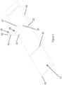
- the flooring board spacing assembly 10 has an elongate platform member 12.
- a plurality of first spacers 20 extend from the platform member 12.
- An end spacer 21 extends from the platform member 12.
- the end spacer 21 is the same as a first spacer 20.
- a plurality of second spacers 30 extend from the platform member 12.
- the platform member 12 has a plurality of apertures 40 are formed in the platform member 12.
- the platform member 12 has flanges 50 which extend at a downwardly angle.
- the platform member 12 is locatable on a flooring joist (not shown).
- the top of the platform member 12 and the flanges 50 inhibit water from pooling on the flooring joist.
- Decking boards (not shown) are locatable on the platform member 12 and spaced from one another by the first spacers 20 and the second spacers 30.
- the first spacers 20 are attached to the platform member 12 by tabs 22.
- the tabs 22 are thinner than the main portion of the first spacers 20.
- the tabs 22 allow the first spacers 20 to be removed from the platform member 12. Typically, the tabs 22 break when the first spacers 20 are pulled from the platform member 12.
- the first spacers 20 have two spacing ribs 24,25 extending from the first side of the first spacers 20 and two spacing ribs 26,27 extending from the second side.
- the spacing ribs 24,25 on the first side are offset from the spacing ribs 26,27 on the second side.
- the first spacers 20 have a recess 28 formed in a top portion thereof.
- the second spacers 30 have two spacing ribs 32,34 extending from the first side of the second spacers 30 and two spacing ribs 36,38 extending from the second side.
- decking boards 60 located on top of the platform member 12.
- the decking boards 60 are spaced from one another by the first spacers 20 and the second spacers 30.
- the height of the second spacers 30 is less than the thickness of the decking boards 60.
- the first spacers 20 protrude above the thickness of the decking boards 60 so that the first spacers 20 can be pulled from the platform member 12 after the decking boards 60 have been attached to the flooring joist (not shown) and the platform member 12.
- Figures 9 and 10 show an elongate fixing jig 70 of a flooring board spacing according to an embodiment of the invention.
- the fixing jig 70 has a plurality of apertures 72.
- a drill bit can be aligned with the apertures 72 so that holes can be drilled into the decking boards at predetermined locations.
- the holes are typically drilled into the platform member and the flooring joist as well.
- the fixing jig 70 has protrusions 74.
- the protrusions 74 can be inserted into spaces between the decking boards to align the fixing jig 70 with the decking boards.
- the fixing jig 70 also has notches 76. The notches 76 engage with the tops of the first spacers (20 as seen in Figure 1 ) to align the fixing jig 70 with the platform member (12 as seen in Figure 1 ).
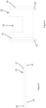
- Figures 11 and 12 show an elongate bearer platform 80 of a flooring board spacing according to an embodiment of the invention.
- the bearer platform 80 is locatable between a bearer and a flooring joist.
- the bearer platform 80 has markings 82,84 indicating predetermined spacings for flooring joists.
- the markings 82 are spaced at 450mm and the markings 84 are spaced at 500mm.
- the markings 82,84 include a line that extends from the bearer platform 80.
- Flooring joists can be abutted against the lines of the markings 82,84.
- the bearer platform 80 further includes flanges 86 extending at a downward angle relative to a top surface of the bearer platform 80. The flanges 86 and the bearer platform 80 inhibit liquid from pooling on top of a bearer.
- bearer platforms 80 are located on and attached to bearers (not shown).
- Flooring joists are located on top of the bearer platforms 80 and aligned with the markings 82 at 450mm spacings or the markings 84 at 500mm spacings. The flooring joists are then attached to the bearers.
- Platform members 12 are located on and attached to the flooring joists.
- Decking boards 60 are located on the platform members 12 and spaced from each other by first spacers 20 and second spacers 30.
- the fixing jig 70 is located on top of the decking boards 60 and the platform member 12 such that the protrusions 74 are inserted into spaces between the decking boards 60 and such that the notches 76 engage with the first spacers 20 to align the fixing jig 70 relative to the platform member 12.
- a drill bit is aligned with the apertures 72 and holes are drilled into the decking boards 60, the platform member 12 and the flooring joist. After the holes have been drilled, fasteners in the form of screws, nails or the like are used to attach the decking boards 60 to the platform member 12 and the flooring joist.
- the first spacers 20 are pulled from the platform member 12. Pulling the first spacers 20 from the platform member 12 breaks the tabs 22 attaching the first spacers 20 to the platform member 12. As the spacing ribs 24,25 are offset from spacing ribs 26,27, twisting the spacers 20 can reduce the effective thickness of the spacers 20, making it easier to remove the first spacers 20 from between the decking boards 60. After the first spacers are removed, the decking boards 60 have enough space to expand with an increase in heat and or humidity.
- An advantage of the preferred embodiment of the flooring board spacing assembly includes the ability to space multiple flooring boards without having to sequentially space and fix the flooring boards. Another advantage of the preferred embodiment of the flooring board spacing assembly includes accurate spacing between flooring boards. An additional advantage of the preferred embodiment of the flooring board spacing assembly includes allowing the flooring boards to expand after they have been attached to the flooring joist. A further advantage of the preferred embodiment of the flooring board spacing assembly includes protecting the flooring joists from liquids which could pool on the top of the flooring joists and cause damage. Another advantage of the preferred embodiment of the flooring board spacing assembly includes that the flooring boards can be installed by multiple users at the same time.
Landscapes
- Engineering & Computer Science (AREA)
- Architecture (AREA)
- Civil Engineering (AREA)
- Structural Engineering (AREA)
- Floor Finish (AREA)
Claims (13)
- Bodenplattenabstandshalter (10), der ein längliches Plattformelement (12) einschließt, das auf einem Fußbodenbalken angeordnet werden kann, wobei das Plattformelement (12) eine Vielzahl von ersten Distanzstücken (20) aufweist, die gleichmäßig in regelmäßigen Abständen entlang der Länge des Plattformelements (12) angeordnet ist, und wobei im Gebrauch jedes der ersten Distanzstücke (20) zwischen benachbarten Bodenplatten, die sich auf dem Plattformelement (12) befinden, angeordnet ist und diese beabstandet und einen vorbestimmten Raum zwischen den benachbarten Bodenplatten bildet, dadurch gekennzeichnet, dass jedes der ersten Distanzstücke (20) durch eine oder mehrere abbrechbare Laschen (22) entfernbar an dem Plattformelement (12) befestigt ist.
- Bodenplattenabstandshalter (10) nach Anspruch 1, ferner einschließend eine längliche Befestigungsschablone (70), die über den Bodenplatten angeordnet werden kann und durch die Vielzahl der ersten Distanzstücke (20) ausrichtbar ist, wobei die Befestigungsschablone (70) eine Vielzahl von Öffnungen (72) aufweist, um einen Bohrer so auszurichten, dass Löcher an vordefinierten Stellen in die Bodenplatten gebohrt werden können, wobei die längliche Befestigungsschablone (70) im Wesentlichen parallel zu dem länglichen Plattformelement (12) angeordnet ist.
- Bodenplattenabstandshalter (10) nach Anspruch 2, wobei jedes der ersten Distanzstücke (20) eine Aussparung (28) aufweist, die in einem oberen Abschnitt davon ausgebildet ist, und wobei die Befestigungsschablone (70) mindestens teilweise in die Aussparung (28) von jedem der ersten Distanzstücke (20) einführbar ist.
- Bodenplattenabstandshalter (10) nach einem der Ansprüche 1 bis 3, ferner einschließend eine längliche Trägerplattform (80), die zwischen einem Träger und dem Fußbodenbalken eingeschlagen werden kann, wobei die Trägerplattform (80) Markierungen (82, 84) einschließt, die vorbestimmte Abstände für Fußbodenbalken anzeigen.
- Bodenplattenabstandshalter (10) nach einem der vorhergehenden Ansprüche, wobei jedes der ersten Distanzstücke (20) mindestens eine Distanzrippe (24, 25) aufweist, die sich von einer ersten Seite davon erstreckt, und mindestens eine Distanzrippe (26, 27) aufweist, die sich von einer zweiten Seite davon erstreckt.
- Bodenplattenabstandshalter (10) nach Anspruch 5, wobei die mindestens eine Distanzrippe (24, 25), die sich von der ersten Seite erstreckt, gegenüber der mindestens einen Distanzrippe (26, 27), die sich von der zweiten Seite erstreckt, versetzt ist
- Bodenplattenabstandshalter (10) nach einem der vorhergehenden Ansprüche, wobei das Plattformelement (12) Flansche (50) aufweist, die sich von den lateralen Seiten des Plattformelements in einem nach unten gerichteten Winkel relativ zu einer oberen Fläche des Plattformelements (12) erstrecken.
- Bodenplattenabstandshalter (10) nach einem der vorhergehenden Ansprüche, wobei das Plattformelement (12) eine Vielzahl von Öffnungen (40) aufweist, so dass das Plattformelement (12) durch Befestigungselemente an dem Fußbodenbalken befestigt werden kann.
- Bodenplattenabstandshalter (10) nach einem der vorhergehenden Ansprüche, wobei das Plattformelement (12) ferner eine Vielzahl von zweiten Distanzstücken (30) einschließt, die sich davon erstrecken, wobei die zweiten Distanzstücke (30) in regelmäßigen Abständen entlang der Länge des Plattformelements (12) gleichmäßig beabstandet sind, und wobei bei der Verwendung jedes der zweiten Distanzstücke (30) geeignet ist, zwei benachbarte Bodenplatten, die sich auf dem Plattformelement (12) befinden, zu beabstanden.
- Bodenplattenabstandshalter (10) nach Anspruch 9, wobei jedes der zweiten Distanzstücke (30) sich von dem Plattformelement (12) aus weniger als die Dicke einer Bodenplatte erstreckt, die auf dem Plattformelement (12) angeordnet werden soll, und wobei jedes der zweiten Distanzstücke (30) zwischen zwei benachbarten ersten Distanzstücken (20) angeordnet ist.
- Bodenplattenabstandshalter (10) nach Anspruch 1, ferner einschließendeine längliche Trägerplattform (80), die zwischen einem Träger und dem Fußbodenbalken angeordnet werden kann; undeine längliche Befestigungsschablone (70), die eine Vielzahl von Öffnungen (72) aufweist, wobei die Befestigungsschablone (70) so über den Bodenplatten angeordnet werden kann, dass die längliche Befestigungsschablone (70) durch die Vielzahl der ersten Distanzstücke (20) ausgerichtet wird.
- Verfahren zum Installieren von Deckplatten (60) unter Verwendung eines Bodenplattenabstandshalters nach einem der vorhergehenden Ansprüche, einschließend die Schritte des Anordnens des länglichen Plattformelements (12) auf einem Fußbodenbalken, wobei das längliche Plattformelement (12) die Vielzahl von ersten Distanzstücken (20) aufweist, die gleichmäßig in regelmäßigen Abständen entlang der Länge des Plattformelements (12) angeordnet sind;
Anordnen von Deckplatten (60) auf dem länglichen Plattformelement (12), sodass jede Deckplatte an mindestens einem der Vielzahl von ersten Distanzstücken (20) anliegt, sodass die ersten Distanzstücke (20) zwischen benachbarten Bodenplatten angeordnet sind und diese beabstanden; Befestigen jeder der Deckplatten an dem Fußbodenbalken; und Entfernen der Vielzahl von ersten Distanzstücken (20) von dem Plattformelement (12). - Verfahren zum Installieren von Deckplatten nach Anspruch 12, wobei der Schritt des Entfernens der Vielzahl von ersten Distanzstücken (20) von dem Plattformelement (12) Brechen der Laschen (22) einschließt, die die Vielzahl von ersten Distanzstücken (20) mit dem Plattformelement (12) verbinden, wobei die Laschen (22) durch Abziehen jedes der ersten Distanzstücke (20) von der Plattform gebrochen werden.
Applications Claiming Priority (3)
| Application Number | Priority Date | Filing Date | Title |
|---|---|---|---|
| AU2017100418A AU2017100418A4 (en) | 2017-04-12 | 2017-04-12 | A flooring board spacing assembly |
| AU2017202416A AU2017202416B2 (en) | 2017-04-12 | 2017-04-12 | A flooring board spacing assembly |
| PCT/AU2018/050325 WO2018187837A1 (en) | 2017-04-12 | 2018-04-10 | A flooring board spacing assembly |
Publications (3)
| Publication Number | Publication Date |
|---|---|
| EP3610096A1 EP3610096A1 (de) | 2020-02-19 |
| EP3610096A4 EP3610096A4 (de) | 2021-01-13 |
| EP3610096B1 true EP3610096B1 (de) | 2023-06-07 |
Family
ID=63792159
Family Applications (1)
| Application Number | Title | Priority Date | Filing Date |
|---|---|---|---|
| EP18785060.7A Active EP3610096B1 (de) | 2017-04-12 | 2018-04-10 | Bodenplattenabstandshalter |
Country Status (4)
| Country | Link |
|---|---|
| US (1) | US11719002B2 (de) |
| EP (1) | EP3610096B1 (de) |
| CA (1) | CA3059814A1 (de) |
| WO (1) | WO2018187837A1 (de) |
Families Citing this family (2)
| Publication number | Priority date | Publication date | Assignee | Title |
|---|---|---|---|---|
| WO2021119509A1 (en) * | 2019-12-13 | 2021-06-17 | Tarpey James | Load distributing deck insert |
| US12084872B2 (en) * | 2021-12-30 | 2024-09-10 | Innovative Enterprises of Princeton, LLC | Deck installation device and a method of using said device |
Family Cites Families (43)
| Publication number | Priority date | Publication date | Assignee | Title |
|---|---|---|---|---|
| US3020602A (en) * | 1957-11-07 | 1962-02-13 | Johns Manville | Wallboard fastener |
| US3267630A (en) * | 1964-04-20 | 1966-08-23 | Powerlock Floors Inc | Flooring systems |
| US3390494A (en) * | 1966-04-05 | 1968-07-02 | Pete R. Chappie | Strip for spacing and holding building members |
| US3903670A (en) * | 1973-08-20 | 1975-09-09 | Mak Rite Mfg Inc | Apparatus and method for hanging siding members on supporting surfaces |
| US4594823A (en) * | 1982-09-29 | 1986-06-17 | Hague James G | Panel support assembly for concealed fastener roof structure |
| US4858399A (en) * | 1988-08-22 | 1989-08-22 | Salato Jr Peter A | Protective covering and spacer strip for a deck |
| US5870874A (en) * | 1997-08-07 | 1999-02-16 | Brothers; Jack | Means for spacing and fastening structural members in juxtaposition |
| HK1047460A1 (zh) * | 1999-04-30 | 2003-02-21 | Donnellan Anthony | 一種瓷磚輔助部件 |
| US7028446B2 (en) * | 1999-07-16 | 2006-04-18 | Winchester Richard M | Construction layout stripping having a plurality of pairs of uprights thereon |
| AUPQ793400A0 (en) | 2000-06-02 | 2000-06-29 | Proud, Brian | Decking strip |
| US7353640B2 (en) * | 2001-02-27 | 2008-04-08 | Mark Stutler | Fresh masonry wall protection device and method for rapidly protecting a newly laid masonry wall |
| US20030159399A1 (en) * | 2002-01-18 | 2003-08-28 | Werren William C. | Deck spacer |
| US7207150B2 (en) | 2003-06-12 | 2007-04-24 | Simpson Strong-Tie Company, Inc. | Deck board tie connector, connection and method |
| US7398620B1 (en) * | 2004-11-17 | 2008-07-15 | Jones Terry V | Universal structural member support and positioning system |
| WO2009099664A1 (en) * | 2008-02-07 | 2009-08-13 | Tinnerman Palnut Engineered Products | Deck clip |
| US20100083610A1 (en) * | 2008-10-02 | 2010-04-08 | Robert King | Installation pilot device and method |
| US8079199B1 (en) * | 2010-08-03 | 2011-12-20 | Davinci Italia/Usa Group, Llc | Tile alignment and leveling device |
| WO2013134119A2 (en) * | 2012-03-05 | 2013-09-12 | Hinkle Donald G | Integrated decking member fastening track system installation method and tool |
| US20120090256A1 (en) | 2010-10-14 | 2012-04-19 | Andrews Robin D | Three dimensional tiled deck accessories |
| US20120180422A1 (en) * | 2010-11-17 | 2012-07-19 | Noturno Sam P | Truss spacer |
| AU2011201974A1 (en) * | 2011-03-08 | 2012-09-27 | Turner, Arthur Raymond Mr | Building Means |
| US8615958B2 (en) * | 2011-07-13 | 2013-12-31 | A. Raymond Et Cie | Stepped hidden decking system with fastener |
| US9297161B2 (en) * | 2011-09-15 | 2016-03-29 | Sr Systems Llc | Roof member anti-torsion bracket device and method of use |
| US8793889B2 (en) * | 2012-01-11 | 2014-08-05 | James D. Hovren | Deck board placement tool |
| US9416546B2 (en) | 2012-01-24 | 2016-08-16 | Mark Claudin | Deck installation track and method |
| AU2013101763A4 (en) | 2012-05-08 | 2016-09-08 | Richard Keith Bawden | Decking System |
| ITTO20120552A1 (it) * | 2012-06-22 | 2013-12-23 | Mauro Ettore Paris | Pannello modulare per la composizione di pavimentazioni o pareti ventilate |
| US9624677B2 (en) * | 2012-07-05 | 2017-04-18 | Pergo (Europe) Ab | Joint devices, systems, and methods for exterior flooring |
| AU2012101175B4 (en) * | 2012-08-01 | 2014-07-31 | Gorton, Michael Mr | Tile levelling device |
| FI20135129L (fi) | 2013-02-13 | 2014-08-14 | Peltitarvike Oy | Menetelmä rakenneosien kiinnittämiseksi, kiinnitysosa sekä järjestelmä |
| ES2955618T3 (es) * | 2013-03-13 | 2023-12-04 | The Ipe Clip Fastener Company Llc | Un conjunto de cabezal nivelador para un pedestal nivelador elevador, dicho pedestal nivelador elevador y un método de fabricación de un pedestal nivelador elevador |
| US9297397B2 (en) * | 2013-03-15 | 2016-03-29 | MarPec, Inc. | Snap lock decking system |
| US9487959B2 (en) * | 2013-04-09 | 2016-11-08 | Clinton D. Bunch | Device for leveling and aligning tiles and method for leveling and aligning tiles |
| AU2014262380B2 (en) | 2013-05-09 | 2017-04-27 | David Chester | A deck fastening system |
| US9181716B1 (en) * | 2013-07-16 | 2015-11-10 | Brent Alan Gibson | System for mounting elongated panels to a substructure |
| DE202014000276U1 (de) | 2014-01-16 | 2014-04-29 | Manfred Henfling | Balkonsystem |
| FR3018838B1 (fr) * | 2014-03-21 | 2016-03-11 | Wilfried Andres | Systeme de fixation de lattes pour former un sol ou plancher rehausse. |
| US9322186B1 (en) * | 2015-02-10 | 2016-04-26 | Jason Chang | Leveling spacer system for panel members |
| US9562365B2 (en) * | 2015-05-05 | 2017-02-07 | Metronic Technologies Corporation | Device for installing tiles |
| US9458635B1 (en) | 2015-09-22 | 2016-10-04 | Jeffrey Sargen | Stringer for decking |
| US10961719B2 (en) * | 2017-02-21 | 2021-03-30 | Klevaklip Systems Pty Ltd. | Decking clip |
| GB2560166B (en) * | 2017-02-28 | 2020-07-15 | The Decking Tool Ltd | A deck construction device |
| AU2018253529B2 (en) * | 2017-11-03 | 2022-05-26 | Simpson Strong-Tie Australia Pty Limited | A Decking Clip |
-
2018
- 2018-04-10 WO PCT/AU2018/050325 patent/WO2018187837A1/en not_active Ceased
- 2018-04-10 CA CA3059814A patent/CA3059814A1/en active Pending
- 2018-04-10 EP EP18785060.7A patent/EP3610096B1/de active Active
- 2018-04-10 US US16/500,135 patent/US11719002B2/en active Active
Also Published As
| Publication number | Publication date |
|---|---|
| WO2018187837A1 (en) | 2018-10-18 |
| US11719002B2 (en) | 2023-08-08 |
| US20210102384A1 (en) | 2021-04-08 |
| CA3059814A1 (en) | 2018-10-18 |
| EP3610096A1 (de) | 2020-02-19 |
| EP3610096A4 (de) | 2021-01-13 |
Similar Documents
| Publication | Publication Date | Title |
|---|---|---|
| US20090266018A1 (en) | Deck drainage system | |
| JP2003527503A (ja) | コンクリート打ち込みの金属デッキフロア又は木枠フロアに用いるネジ付きアンカー | |
| US9404277B2 (en) | Apparatus for positioning anchor bolts | |
| US10612574B1 (en) | Insulation retainer clip | |
| US20120292474A1 (en) | Strip with resilient braces for fastening perpendicularly attached siding panels | |
| EP3610096B1 (de) | Bodenplattenabstandshalter | |
| WO2014176692A1 (en) | Cross braced joist hanger | |
| KR101557419B1 (ko) | 단부의 변형방지를 위한 보강부를 구비한 데크 및 이를 사용하여 시공한 데크 설치구조 | |
| US20090019804A1 (en) | Tracks, methods for use thereof, and apparatus, system, and method for manufacture | |
| US8453392B1 (en) | System for positioning and holding ceiling panels | |
| AU2017202416B2 (en) | A flooring board spacing assembly | |
| US10301829B2 (en) | Framing system and method of assembly thereof | |
| AU2017100418A4 (en) | A flooring board spacing assembly | |
| US20110081198A1 (en) | Fastener, system and method for connecting elongated members | |
| JP4675978B2 (ja) | デッキ材固定金具およびデッキ材固定方法 | |
| KR102561997B1 (ko) | 클립을 포함하는 데크재 | |
| US20060137285A1 (en) | Fastener devices | |
| EP3546666A1 (de) | Holz-beton-verbindungsbausatz | |
| US20110078972A1 (en) | Siding Installation Spacer and Method of Installing Siding Using A Siding Installation Spacer | |
| DE102019106018A1 (de) | Holz-Beton-Verbindungsbausatz | |
| EP2336444B1 (de) | Verfahren zur Anbringung von Dämmplatten mit Montagehilfe | |
| JP6613125B2 (ja) | 固定金具 | |
| AU2003100995A4 (en) | Fastener Devices | |
| KR101923024B1 (ko) | 가설용 흙막이 구조물 및 그 시공 방법 | |
| JP3101136U (ja) | 根太材と床材の固定金具 |
Legal Events
| Date | Code | Title | Description |
|---|---|---|---|
| STAA | Information on the status of an ep patent application or granted ep patent |
Free format text: STATUS: THE INTERNATIONAL PUBLICATION HAS BEEN MADE |
|
| PUAI | Public reference made under article 153(3) epc to a published international application that has entered the european phase |
Free format text: ORIGINAL CODE: 0009012 |
|
| STAA | Information on the status of an ep patent application or granted ep patent |
Free format text: STATUS: REQUEST FOR EXAMINATION WAS MADE |
|
| 17P | Request for examination filed |
Effective date: 20191111 |
|
| AK | Designated contracting states |
Kind code of ref document: A1 Designated state(s): AL AT BE BG CH CY CZ DE DK EE ES FI FR GB GR HR HU IE IS IT LI LT LU LV MC MK MT NL NO PL PT RO RS SE SI SK SM TR |
|
| AX | Request for extension of the european patent |
Extension state: BA ME |
|
| DAV | Request for validation of the european patent (deleted) | ||
| DAX | Request for extension of the european patent (deleted) | ||
| A4 | Supplementary search report drawn up and despatched |
Effective date: 20201211 |
|
| RIC1 | Information provided on ipc code assigned before grant |
Ipc: E04F 15/02 20060101AFI20201207BHEP Ipc: E04F 21/18 20060101ALI20201207BHEP Ipc: E04F 21/00 20060101ALI20201207BHEP Ipc: E04F 21/22 20060101ALI20201207BHEP |
|
| GRAP | Despatch of communication of intention to grant a patent |
Free format text: ORIGINAL CODE: EPIDOSNIGR1 |
|
| STAA | Information on the status of an ep patent application or granted ep patent |
Free format text: STATUS: GRANT OF PATENT IS INTENDED |
|
| INTG | Intention to grant announced |
Effective date: 20220928 |
|
| GRAS | Grant fee paid |
Free format text: ORIGINAL CODE: EPIDOSNIGR3 |
|
| RIN1 | Information on inventor provided before grant (corrected) |
Inventor name: HAAS, PETER |
|
| GRAA | (expected) grant |
Free format text: ORIGINAL CODE: 0009210 |
|
| STAA | Information on the status of an ep patent application or granted ep patent |
Free format text: STATUS: THE PATENT HAS BEEN GRANTED |
|
| AK | Designated contracting states |
Kind code of ref document: B1 Designated state(s): AL AT BE BG CH CY CZ DE DK EE ES FI FR GB GR HR HU IE IS IT LI LT LU LV MC MK MT NL NO PL PT RO RS SE SI SK SM TR |
|
| REG | Reference to a national code |
Ref country code: GB Ref legal event code: FG4D |
|
| REG | Reference to a national code |
Ref country code: CH Ref legal event code: EP Ref country code: AT Ref legal event code: REF Ref document number: 1575489 Country of ref document: AT Kind code of ref document: T Effective date: 20230615 |
|
| REG | Reference to a national code |
Ref country code: DE Ref legal event code: R096 Ref document number: 602018051243 Country of ref document: DE |
|
| REG | Reference to a national code |
Ref country code: LT Ref legal event code: MG9D |
|
| REG | Reference to a national code |
Ref country code: NL Ref legal event code: MP Effective date: 20230607 |
|
| PG25 | Lapsed in a contracting state [announced via postgrant information from national office to epo] |
Ref country code: SE Free format text: LAPSE BECAUSE OF FAILURE TO SUBMIT A TRANSLATION OF THE DESCRIPTION OR TO PAY THE FEE WITHIN THE PRESCRIBED TIME-LIMIT Effective date: 20230607 Ref country code: NO Free format text: LAPSE BECAUSE OF FAILURE TO SUBMIT A TRANSLATION OF THE DESCRIPTION OR TO PAY THE FEE WITHIN THE PRESCRIBED TIME-LIMIT Effective date: 20230907 Ref country code: ES Free format text: LAPSE BECAUSE OF FAILURE TO SUBMIT A TRANSLATION OF THE DESCRIPTION OR TO PAY THE FEE WITHIN THE PRESCRIBED TIME-LIMIT Effective date: 20230607 |
|
| REG | Reference to a national code |
Ref country code: AT Ref legal event code: MK05 Ref document number: 1575489 Country of ref document: AT Kind code of ref document: T Effective date: 20230607 |
|
| PG25 | Lapsed in a contracting state [announced via postgrant information from national office to epo] |
Ref country code: RS Free format text: LAPSE BECAUSE OF FAILURE TO SUBMIT A TRANSLATION OF THE DESCRIPTION OR TO PAY THE FEE WITHIN THE PRESCRIBED TIME-LIMIT Effective date: 20230607 Ref country code: NL Free format text: LAPSE BECAUSE OF FAILURE TO SUBMIT A TRANSLATION OF THE DESCRIPTION OR TO PAY THE FEE WITHIN THE PRESCRIBED TIME-LIMIT Effective date: 20230607 Ref country code: LV Free format text: LAPSE BECAUSE OF FAILURE TO SUBMIT A TRANSLATION OF THE DESCRIPTION OR TO PAY THE FEE WITHIN THE PRESCRIBED TIME-LIMIT Effective date: 20230607 Ref country code: LT Free format text: LAPSE BECAUSE OF FAILURE TO SUBMIT A TRANSLATION OF THE DESCRIPTION OR TO PAY THE FEE WITHIN THE PRESCRIBED TIME-LIMIT Effective date: 20230607 Ref country code: HR Free format text: LAPSE BECAUSE OF FAILURE TO SUBMIT A TRANSLATION OF THE DESCRIPTION OR TO PAY THE FEE WITHIN THE PRESCRIBED TIME-LIMIT Effective date: 20230607 Ref country code: GR Free format text: LAPSE BECAUSE OF FAILURE TO SUBMIT A TRANSLATION OF THE DESCRIPTION OR TO PAY THE FEE WITHIN THE PRESCRIBED TIME-LIMIT Effective date: 20230908 |
|
| PG25 | Lapsed in a contracting state [announced via postgrant information from national office to epo] |
Ref country code: FI Free format text: LAPSE BECAUSE OF FAILURE TO SUBMIT A TRANSLATION OF THE DESCRIPTION OR TO PAY THE FEE WITHIN THE PRESCRIBED TIME-LIMIT Effective date: 20230607 |
|
| PG25 | Lapsed in a contracting state [announced via postgrant information from national office to epo] |
Ref country code: SK Free format text: LAPSE BECAUSE OF FAILURE TO SUBMIT A TRANSLATION OF THE DESCRIPTION OR TO PAY THE FEE WITHIN THE PRESCRIBED TIME-LIMIT Effective date: 20230607 |
|
| PG25 | Lapsed in a contracting state [announced via postgrant information from national office to epo] |
Ref country code: IS Free format text: LAPSE BECAUSE OF FAILURE TO SUBMIT A TRANSLATION OF THE DESCRIPTION OR TO PAY THE FEE WITHIN THE PRESCRIBED TIME-LIMIT Effective date: 20231007 |
|
| PG25 | Lapsed in a contracting state [announced via postgrant information from national office to epo] |
Ref country code: SM Free format text: LAPSE BECAUSE OF FAILURE TO SUBMIT A TRANSLATION OF THE DESCRIPTION OR TO PAY THE FEE WITHIN THE PRESCRIBED TIME-LIMIT Effective date: 20230607 Ref country code: SK Free format text: LAPSE BECAUSE OF FAILURE TO SUBMIT A TRANSLATION OF THE DESCRIPTION OR TO PAY THE FEE WITHIN THE PRESCRIBED TIME-LIMIT Effective date: 20230607 Ref country code: RO Free format text: LAPSE BECAUSE OF FAILURE TO SUBMIT A TRANSLATION OF THE DESCRIPTION OR TO PAY THE FEE WITHIN THE PRESCRIBED TIME-LIMIT Effective date: 20230607 Ref country code: PT Free format text: LAPSE BECAUSE OF FAILURE TO SUBMIT A TRANSLATION OF THE DESCRIPTION OR TO PAY THE FEE WITHIN THE PRESCRIBED TIME-LIMIT Effective date: 20231009 Ref country code: IS Free format text: LAPSE BECAUSE OF FAILURE TO SUBMIT A TRANSLATION OF THE DESCRIPTION OR TO PAY THE FEE WITHIN THE PRESCRIBED TIME-LIMIT Effective date: 20231007 Ref country code: EE Free format text: LAPSE BECAUSE OF FAILURE TO SUBMIT A TRANSLATION OF THE DESCRIPTION OR TO PAY THE FEE WITHIN THE PRESCRIBED TIME-LIMIT Effective date: 20230607 Ref country code: CZ Free format text: LAPSE BECAUSE OF FAILURE TO SUBMIT A TRANSLATION OF THE DESCRIPTION OR TO PAY THE FEE WITHIN THE PRESCRIBED TIME-LIMIT Effective date: 20230607 Ref country code: AT Free format text: LAPSE BECAUSE OF FAILURE TO SUBMIT A TRANSLATION OF THE DESCRIPTION OR TO PAY THE FEE WITHIN THE PRESCRIBED TIME-LIMIT Effective date: 20230607 |
|
| PG25 | Lapsed in a contracting state [announced via postgrant information from national office to epo] |
Ref country code: PL Free format text: LAPSE BECAUSE OF FAILURE TO SUBMIT A TRANSLATION OF THE DESCRIPTION OR TO PAY THE FEE WITHIN THE PRESCRIBED TIME-LIMIT Effective date: 20230607 |
|
| REG | Reference to a national code |
Ref country code: DE Ref legal event code: R097 Ref document number: 602018051243 Country of ref document: DE |
|
| PLBE | No opposition filed within time limit |
Free format text: ORIGINAL CODE: 0009261 |
|
| STAA | Information on the status of an ep patent application or granted ep patent |
Free format text: STATUS: NO OPPOSITION FILED WITHIN TIME LIMIT |
|
| PG25 | Lapsed in a contracting state [announced via postgrant information from national office to epo] |
Ref country code: DK Free format text: LAPSE BECAUSE OF FAILURE TO SUBMIT A TRANSLATION OF THE DESCRIPTION OR TO PAY THE FEE WITHIN THE PRESCRIBED TIME-LIMIT Effective date: 20230607 |
|
| PG25 | Lapsed in a contracting state [announced via postgrant information from national office to epo] |
Ref country code: SI Free format text: LAPSE BECAUSE OF FAILURE TO SUBMIT A TRANSLATION OF THE DESCRIPTION OR TO PAY THE FEE WITHIN THE PRESCRIBED TIME-LIMIT Effective date: 20230607 |
|
| 26N | No opposition filed |
Effective date: 20240308 |
|
| PG25 | Lapsed in a contracting state [announced via postgrant information from national office to epo] |
Ref country code: SI Free format text: LAPSE BECAUSE OF FAILURE TO SUBMIT A TRANSLATION OF THE DESCRIPTION OR TO PAY THE FEE WITHIN THE PRESCRIBED TIME-LIMIT Effective date: 20230607 Ref country code: IT Free format text: LAPSE BECAUSE OF FAILURE TO SUBMIT A TRANSLATION OF THE DESCRIPTION OR TO PAY THE FEE WITHIN THE PRESCRIBED TIME-LIMIT Effective date: 20230607 |
|
| REG | Reference to a national code |
Ref country code: DE Ref legal event code: R119 Ref document number: 602018051243 Country of ref document: DE |
|
| PG25 | Lapsed in a contracting state [announced via postgrant information from national office to epo] |
Ref country code: BG Free format text: LAPSE BECAUSE OF FAILURE TO SUBMIT A TRANSLATION OF THE DESCRIPTION OR TO PAY THE FEE WITHIN THE PRESCRIBED TIME-LIMIT Effective date: 20230607 |
|
| PG25 | Lapsed in a contracting state [announced via postgrant information from national office to epo] |
Ref country code: MC Free format text: LAPSE BECAUSE OF FAILURE TO SUBMIT A TRANSLATION OF THE DESCRIPTION OR TO PAY THE FEE WITHIN THE PRESCRIBED TIME-LIMIT Effective date: 20230607 |
|
| PG25 | Lapsed in a contracting state [announced via postgrant information from national office to epo] |
Ref country code: MC Free format text: LAPSE BECAUSE OF FAILURE TO SUBMIT A TRANSLATION OF THE DESCRIPTION OR TO PAY THE FEE WITHIN THE PRESCRIBED TIME-LIMIT Effective date: 20230607 Ref country code: BG Free format text: LAPSE BECAUSE OF FAILURE TO SUBMIT A TRANSLATION OF THE DESCRIPTION OR TO PAY THE FEE WITHIN THE PRESCRIBED TIME-LIMIT Effective date: 20230607 |
|
| REG | Reference to a national code |
Ref country code: CH Ref legal event code: PL |
|
| PG25 | Lapsed in a contracting state [announced via postgrant information from national office to epo] |
Ref country code: LU Free format text: LAPSE BECAUSE OF NON-PAYMENT OF DUE FEES Effective date: 20240410 |
|
| GBPC | Gb: european patent ceased through non-payment of renewal fee |
Effective date: 20240410 |
|
| REG | Reference to a national code |
Ref country code: BE Ref legal event code: MM Effective date: 20240430 |
|
| PG25 | Lapsed in a contracting state [announced via postgrant information from national office to epo] |
Ref country code: LU Free format text: LAPSE BECAUSE OF NON-PAYMENT OF DUE FEES Effective date: 20240410 |
|
| PG25 | Lapsed in a contracting state [announced via postgrant information from national office to epo] |
Ref country code: DE Free format text: LAPSE BECAUSE OF NON-PAYMENT OF DUE FEES Effective date: 20241105 |
|
| PG25 | Lapsed in a contracting state [announced via postgrant information from national office to epo] |
Ref country code: BE Free format text: LAPSE BECAUSE OF NON-PAYMENT OF DUE FEES Effective date: 20240430 |
|
| PG25 | Lapsed in a contracting state [announced via postgrant information from national office to epo] |
Ref country code: GB Free format text: LAPSE BECAUSE OF NON-PAYMENT OF DUE FEES Effective date: 20240410 |
|
| PG25 | Lapsed in a contracting state [announced via postgrant information from national office to epo] |
Ref country code: FR Free format text: LAPSE BECAUSE OF NON-PAYMENT OF DUE FEES Effective date: 20240430 |
|
| PG25 | Lapsed in a contracting state [announced via postgrant information from national office to epo] |
Ref country code: GB Free format text: LAPSE BECAUSE OF NON-PAYMENT OF DUE FEES Effective date: 20240410 Ref country code: FR Free format text: LAPSE BECAUSE OF NON-PAYMENT OF DUE FEES Effective date: 20240430 Ref country code: DE Free format text: LAPSE BECAUSE OF NON-PAYMENT OF DUE FEES Effective date: 20241105 Ref country code: BE Free format text: LAPSE BECAUSE OF NON-PAYMENT OF DUE FEES Effective date: 20240430 Ref country code: CH Free format text: LAPSE BECAUSE OF NON-PAYMENT OF DUE FEES Effective date: 20240430 |
|
| PG25 | Lapsed in a contracting state [announced via postgrant information from national office to epo] |
Ref country code: IE Free format text: LAPSE BECAUSE OF NON-PAYMENT OF DUE FEES Effective date: 20240410 |
|
| PG25 | Lapsed in a contracting state [announced via postgrant information from national office to epo] |
Ref country code: CY Free format text: LAPSE BECAUSE OF FAILURE TO SUBMIT A TRANSLATION OF THE DESCRIPTION OR TO PAY THE FEE WITHIN THE PRESCRIBED TIME-LIMIT; INVALID AB INITIO Effective date: 20180410 |
|
| PG25 | Lapsed in a contracting state [announced via postgrant information from national office to epo] |
Ref country code: HU Free format text: LAPSE BECAUSE OF FAILURE TO SUBMIT A TRANSLATION OF THE DESCRIPTION OR TO PAY THE FEE WITHIN THE PRESCRIBED TIME-LIMIT; INVALID AB INITIO Effective date: 20180410 |