EP3610125B1 - Ensemble de raccordement de tube de dérivation - Google Patents
Ensemble de raccordement de tube de dérivation Download PDFInfo
- Publication number
- EP3610125B1 EP3610125B1 EP18720752.7A EP18720752A EP3610125B1 EP 3610125 B1 EP3610125 B1 EP 3610125B1 EP 18720752 A EP18720752 A EP 18720752A EP 3610125 B1 EP3610125 B1 EP 3610125B1
- Authority
- EP
- European Patent Office
- Prior art keywords
- pin
- tube
- connection
- shunt
- bore
- Prior art date
- Legal status (The legal status is an assumption and is not a legal conclusion. Google has not performed a legal analysis and makes no representation as to the accuracy of the status listed.)
- Active
Links
Images






Classifications
-
- E—FIXED CONSTRUCTIONS
- E21—EARTH OR ROCK DRILLING; MINING
- E21B—EARTH OR ROCK DRILLING; OBTAINING OIL, GAS, WATER, SOLUBLE OR MELTABLE MATERIALS OR A SLURRY OF MINERALS FROM WELLS
- E21B17/00—Drilling rods or pipes; Flexible drill strings; Kellies; Drill collars; Sucker rods; Cables; Casings; Tubings
- E21B17/02—Couplings; joints
- E21B17/04—Couplings; joints between rod or the like and bit or between rod and rod or the like
- E21B17/046—Couplings; joints between rod or the like and bit or between rod and rod or the like with ribs, pins, or jaws, and complementary grooves or the like, e.g. bayonet catches
-
- E—FIXED CONSTRUCTIONS
- E21—EARTH OR ROCK DRILLING; MINING
- E21B—EARTH OR ROCK DRILLING; OBTAINING OIL, GAS, WATER, SOLUBLE OR MELTABLE MATERIALS OR A SLURRY OF MINERALS FROM WELLS
- E21B43/00—Methods or apparatus for obtaining oil, gas, water, soluble or meltable materials or a slurry of minerals from wells
- E21B43/02—Subsoil filtering
- E21B43/04—Gravelling of wells
- E21B43/045—Crossover tools
-
- F—MECHANICAL ENGINEERING; LIGHTING; HEATING; WEAPONS; BLASTING
- F16—ENGINEERING ELEMENTS AND UNITS; GENERAL MEASURES FOR PRODUCING AND MAINTAINING EFFECTIVE FUNCTIONING OF MACHINES OR INSTALLATIONS; THERMAL INSULATION IN GENERAL
- F16L—PIPES; JOINTS OR FITTINGS FOR PIPES; SUPPORTS FOR PIPES, CABLES OR PROTECTIVE TUBING; MEANS FOR THERMAL INSULATION IN GENERAL
- F16L21/00—Joints with sleeve or socket
- F16L21/02—Joints with sleeve or socket with elastic sealing rings between pipe and sleeve or between pipe and socket, e.g. with rolling or other prefabricated profiled rings
- F16L21/035—Joints with sleeve or socket with elastic sealing rings between pipe and sleeve or between pipe and socket, e.g. with rolling or other prefabricated profiled rings placed around the spigot end before connection
-
- F—MECHANICAL ENGINEERING; LIGHTING; HEATING; WEAPONS; BLASTING
- F16—ENGINEERING ELEMENTS AND UNITS; GENERAL MEASURES FOR PRODUCING AND MAINTAINING EFFECTIVE FUNCTIONING OF MACHINES OR INSTALLATIONS; THERMAL INSULATION IN GENERAL
- F16L—PIPES; JOINTS OR FITTINGS FOR PIPES; SUPPORTS FOR PIPES, CABLES OR PROTECTIVE TUBING; MEANS FOR THERMAL INSULATION IN GENERAL
- F16L21/00—Joints with sleeve or socket
- F16L21/08—Joints with sleeve or socket with additional locking means
-
- F—MECHANICAL ENGINEERING; LIGHTING; HEATING; WEAPONS; BLASTING
- F16—ENGINEERING ELEMENTS AND UNITS; GENERAL MEASURES FOR PRODUCING AND MAINTAINING EFFECTIVE FUNCTIONING OF MACHINES OR INSTALLATIONS; THERMAL INSULATION IN GENERAL
- F16L—PIPES; JOINTS OR FITTINGS FOR PIPES; SUPPORTS FOR PIPES, CABLES OR PROTECTIVE TUBING; MEANS FOR THERMAL INSULATION IN GENERAL
- F16L27/00—Adjustable joints; Joints allowing movement
- F16L27/08—Adjustable joints; Joints allowing movement allowing adjustment or movement only about the axis of one pipe
Definitions
- a screen is lowered on a workstring into the wellbore and is placed adjacent the subterranean formation.
- Particulate material collectively referred to as "gravel”
- a carrier fluid is pumped as slurry down the workstring.
- the slurry exits through a "cross-over" into the wellbore annulus formed between the screen and the wellbore.
- the carrier fluid in the slurry normally flows into the formation and/or through the screen.
- the screen is sized so that gravel is prevented from flowing through the screen. This results in the gravel being deposited or "screened out” in the annulus between the screen and the wellbore to form a gravel-pack around the screen.
- the gravel is sized so that it forms a permeable mass that allows produced fluids to flow through the mass and into the screen but blocks the flow of particulates into the screen.
- Such bridges block further flow of the slurry through the annulus, thereby preventing the placement of sufficient gravel below the bridge in top-to-bottom packing operations or above the bridge in bottom-to-top packing operations.
- Alternate flow conduits called shunt tubes, can alleviate this bridging problem by providing a flow path for the slurry around such sand bridges.
- the shunt tubes are typically run along the length of the screen and are attached to the screen by welds.
- US 2015/345257 A1 proposes spring clips for a tubular connection.
- connection assembly according to the features specified in the wording of claim 1.
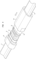
- Figure 1 illustrates an exemplary embodiment of a shunt tube connection assembly 100.
- Figure 1A is a cross-sectional view of the shunt tube connection assembly 100.
- the connection assembly 100 includes a first pin 10 attached to a first shunt tube 5 on a tubular string, such as a screen, a jumper tube 15, a second pin 20 attached to the jumper tube 15, and a movable sleeve 30 disposed around the second pin 20 and engageable with the first pin 10.
- Another connection assembly is provided at the other end of the jumper tube 15 for connection to a second shunt tube on the tubular string.
- the connection assembly 100 may be used to couple the first shunt tube to the second shunt tube and form a sealed passage from the first shunt tube to the second shunt tube.
- the pins 10, 20 are attached to the shunt tube 5 and the jumper tube 15, respectively, by welding.
- Figures 2 and 2D are different perspective views of the first pin 10 according to one embodiment.
- Figures 2A-2C are different cross-sectional views of the first pin 10 of Figures 2 and 2D .
- the first pin 10 includes a pin bore 11 for fluid communication therethrough.
- the back portion 17 of the first pin 10 includes an enlarged bore 12 for receiving the shunt tube 5.
- the pin bore 11 and the enlarged bore 12 are rectangular shaped.
- the outer perimeter of the back portion 17 is larger than the outer perimeter of the front portion 18 such that a shoulder 9 is formed.
- the outer perimeter of the front portion 18 and the back portion 17 may be oval shaped.
- a first recess 13 is formed on the outer surface of the front portion 18 for receiving a sealing member 16 such as an elastomeric o-ring, non-elastomeric ring, a thermoplastic polymer (“PEEK”) ring, and other suitable sealing members.
- a second recess 14 is formed on the outer surface of the front portion 18 for retaining a locking member 19 such as a snap ring, a garter spring, an o-ring, and other suitable locking members.
- the first recess 13 for the sealing member 16 is disposed in front of the second recess 14 for the locking member 19.
- Figures 3, 3C and 3D are different perspective views of the second pin 20 according to one embodiment.
- Figures 3A-3B are different cross-sectional views of the second pin 20 of Figures 3, 3C and 3D .
- the second pin 20 includes a pin bore 21 for fluid communication therethrough.
- the back portion of the second pin 20 includes an enlarged bore 22 for receiving the jumper tube 15.
- the pin bore 21 is substantially the same size as the bore of the jumper tube 15.
- the pin bore 21 and the enlarged bore 22 are rectangular shaped.
- the outer perimeter of the second pin 20 may be oval shaped.
- a recess 23 is formed on the outer surface of the front portion for receiving a sealing member 26 such as an elastomeric o-ring, non-elastomeric ring, a thermoplastic polymer (“PEEK”) ring, and other suitable sealing members.
- a sealing member 26 such as an elastomeric o-ring, non-elastomeric ring, a thermoplastic polymer (“PEEK”) ring, and other suitable sealing members.
- a locking recess may be formed on the second pin 20, in addition to or instead of the locking recess 14 on the first pin 10, to receive a locking member.
- Figures 4 and 4D are different perspective views of the sleeve 30 according to one embodiment.
- Figures 4A-4C are different cross-sectional views of the sleeve 30 of Figures 4 and 4D .
- the sleeve 30 includes a tube bore 31 for housing the second pin 20 and the front portion of the first pin 10.
- the tube bore 31 has an oval shape that is similar to the oval shape of the first and second pins 10, 20.
- the sleeve 30 is axially movable along the second pin 20.
- a recess 33 formed on the inner surface of the tube bore 31 is configured to receive the locking member on the first pin 10.
- the first pin 10 is attached, such as by welding, to one end of a shunt tube 5.
- the second pin 20 is attached to one end of a jumper tube 15.
- the sleeve 30 is disposed around at least a portion of the second pin 20.
- the sleeve 30 is moved axially along the second pin 20 until the sleeve 30 slides over the front end of the first pin 10. See Figure 5 .
- the first pin 10 is moved until the locking member 19 of the first pin 10 engages the locking recess 33 of the sleeve 30.
- the front end of the sleeve 30 abuts the shoulder of the first pin 10.
- the sealing members 16, 26 of the first and second pins 10, 20 sealingly contact the tube bore 31 of the sleeve 30.
- FIG. 6 illustrates an exemplary embodiment of a shunt tube connection assembly 200.
- Figure 7 illustrates an enlarged partial view of the connection assembly 200.
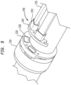
- Figure 8 illustrates a cross-sectional view of the connection assembly 200.
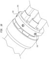
- Figure 9 illustrates the connection assembly 200 prior to connection.
- the connection assembly 200 includes a connection ring 210, an adjustment ring 220, a connection tube 230, a manifold 240, and one or more jumper tubes 215.
- the connection assembly 200 is shown disposed on a tubular string 202, such as a screen.
- the connection ring 210 is configured to sealingly couple a first shunt tube on the screen to the connection assembly 200.
- Another connection assembly is provided at the other end of the jumper tube 215 for connection to a second shunt tube on the tubular string 202.
- connection assembly 200 may be used to couple the first shunt tube to the second shunt tube and form a sealed passage from the first shunt tube to the second shunt tube. While not shown, the shunt tubes may be similar to the shunt tubes 5, 15 shown in Figure 1 .
- the connection ring 210 includes a main bore for accommodating the screen 202.
- the connection ring 200 may have an eccentric shape relative to the screen 202.
- the main bore of the connection ring 210 is an eccentric bore for accommodating the screen 202.
- One or more shunt bores 211 are formed through the connection ring 220 for receiving a shunt tube of the screen 202.
- the shunt bores 211 are formed between the main bore and the outer perimeter of the connection ring 200.
- the connection ring 220 fluidly and sealingly connects the shunt tube of the screen 202 at one end and the connection tube 230 of the connection assembly 200 at the other end.
- two shunt bores 211 are provided in the connection ring 210 for connecting two shunt tubes.
- the shunt bores 211 may have a rectangular shape or any suitable shape that matches the shape of the shunt tube.
- connection tube 230 is configured for insertion into the shunt bore 211 and sealingly engages the shunt bore 211.
- one or more recesses 213 are formed on the outer surface of the connection tube 230 for retaining a sealing member 216 such as an elastomeric o-ring, non-elastomeric ring, a thermoplastic polymer (“PEEK”) ring, and other suitable sealing members.
- the other end of the connection tube 230 is attached to the adjustment ring 220.
- the adjustment ring 220 includes a bore for accommodating the screen 202.
- the adjustment ring 220 may have an eccentric shape relative to the screen 202.
- the adjustment ring 220 is axially movable along the screen 202.
- One or more shunt bores 221 are formed through the adjustment ring 220.
- two shunt bores 221 are provided in the adjustment ring 220.
- the shunt bores 221 may have a rectangular shape.
- One end of the adjustment ring 220 includes an enlarged bore for receiving and forming a seal connection with the connection tube 230. The other end of the adjustment ring 220 sealingly contacts the manifold 240 of the connection assembly 200.
- the end of the adjustment ring 220 facing the manifold 240 includes a groove 226 disposed around each shunt bore 221, as shown in Figure 9 .
- the groove 226 is configured to receive a sealing member such as an elastomeric o-ring, non-elastomeric ring, a thermoplastic polymer (“PEEK”) ring, and other suitable sealing members.
- a sealing member such as an elastomeric o-ring, non-elastomeric ring, a thermoplastic polymer (“PEEK”) ring, and other suitable sealing members.
- the manifold 240 is configured to sealingly couple the jumper tube 215 to the adjustment ring 220.
- the manifold 240 has an arcuate shaped base 242 and two tube receivers 243 extending from the base 242 for receiving the jumper tubes 215.
- the jumper tubes 215 are disposed inside the tube receiver 243 and attached thereto, such as by welding.
- the shunt bores 241 of the manifold 240 are aligned with the shunt bores 221 of the adjustment ring 220.
- the manifold 240 can be attached to the adjustment ring 220 using a suitable fastener, such as a bolt, a screw, or a cam lock. After attachment, the manifold 240 sealingly engages the sealing members of the adjustment ring 220 to form a sealed passage.
- connection ring 210 is pre-attached to the screen 202.
- the connection ring 210 is disposed around the screen 202 and the shunt tubes, such as shunt tubes 15, of the screen 202 are inserted into the shunt bores 211.
- the shunt tubes are sealingly attached to the connection ring 210 such as by welding.
- Figures 10 and 11 illustrate a cam lock 249 for attaching the manifold 240 to the adjustment ring 220.
- the cam lock 249 includes a dowel 258 and a cam receiver 257.
- the dowel 258 may be inserted through the manifold 240 and the adjustment ring 200.
- the cam receiver 257 located in an opening in the adjustment ring 200, is rotated to lock the dowel 258.
- Figure 12 illustrates an exemplary embodiment of a shunt tube connection assembly 300.
- Figures 12A, 12B, and 12C are different, partial cross-sectional views of the connection assembly 300.
- Figure 12D is perspective view of one end of the connection assembly 300.
- the connection assembly 300 includes a first pin 310 attached to a first shunt tube 305 on a tubular string, such as a screen, a jumper tube 315, a second pin 320 attached to the jumper tube 315, and a movable sleeve 330 for engaging with the first pin 310.
- Another connection assembly is provided at the other end of the jumper tube 315 for connection to a second shunt tube on the tubular string.
- connection assembly 300 may be used to couple the first shunt tube to the second shunt tube and form a sealed passage from the first shunt tube to the second shunt tube.
- the pins 310, 320 are attached to the shunt tube 305 and the jumper tube 315, respectively, by welding.
- the first pin 310 includes a pin bore 311 for fluid communication therethrough.
- the back portion of the first pin 310 includes an enlarged bore for receiving the shunt tube 305.
- the pin bore 311 and the enlarged bore are rectangular shaped.
- the outer perimeter of the back portion is larger than the outer perimeter of the front portion such that a shoulder 309 is formed.
- a first recess 313 is formed on the outer surface for receiving a sealing member 316 such as an elastomeric o-ring, non-elastomeric ring, a thermoplastic polymer (“PEEK”) ring, and other suitable sealing members.
- PEEK thermoplastic polymer
- the second pin 320 includes a pin bore 321 for fluid communication therethrough.
- the back portion of the second pin 320 includes an enlarged bore 322 for receiving the jumper tube 315.
- the pin bore 321 and the enlarged bore 322 are rectangular shaped.
- a recess 323 is formed on the outer surface for receiving a sealing member 326 such as an elastomeric o-ring, non-elastomeric ring, a thermoplastic polymer (“PEEK”) ring, and other suitable sealing members.
- the sleeve 330 includes a tube bore 331 for housing the second pin 320 and the front portion of the first pin 310.
- the sleeve 330 is axially movable along the second pin 320 and toward the first pin 310.
- the tube bore 331 can sealingly engage the sealing members 316 and 326 of the first and second pins 310, 320.
- One or more fasteners, such as one or more set screws 348, can be used to lock the sleeve 330 to the second pin 320 and/or the first pin 310.
- a connection assembly for a tube includes a first pin attached to the tube, the first pin having a first sealing member; a second pin attached to a jumper tube, the second pin having a second sealing member; and a movable sleeve configured to sealingly engage the first sealing member and the second sealing member.
- connection assembly includes a locking member for locking the first pin to the movable sleeve.
- the locking member engages a recess in the movable sleeve.
- the locking member is disposed in a recess of the first pin.
- the first sealing member is disposed in a first recess of the first pin.
- the first recess is formed in a smaller outer perimeter portion of the first pin.
- the movable sleeve engages the smaller outer perimeter portion of the first pin.
- connection assembly includes a locking member for locking the first pin to the sleeve.
- the locking member engages a recess in the movable sleeve.
- the locking member is disposed in a second recess of the first pin.
- connection assembly includes a second locking member for locking the second pin to the sleeve.
- the tube attaches to an enlarged bore of the first pin.
- the jumper tube attaches to an enlarged bore of the movable sleeve.
- At least one of the tube and the jumper tube is welded to the first pin and the movable sleeve, respectively.
- a connection assembly for a tube includes a connection ring having a tube bore for receiving the tube; a connection tube attached to an adjustment ring having a tube bore, the connection tube sealingly engageable with the tube bore of the connection ring; a manifold attached to a jumper tube; and a sealing member disposed between the manifold and the adjustment ring.
- the sealing member is disposed on an end of the adjustment ring.
- the sealing member is disposed in a groove surrounding the tube bore of the adjustment ring.
- the adjustment ring is movable relative to the connection ring.
- connection tube includes a sealing member for sealing engagement with the connection ring.
- the first sealing member is disposed in a recess of the connection tube.
- connection ring has an eccentric shape.
- a connection system for connecting a first tube to a second tube includes a jumper tube disposed between a first connector assembly and a second connector assembly.
- the first connector assembly includes a connection ring having a tube bore for receiving the first tube; a connection tube attached to an adjustment ring having a tube bore, the connection tube sealingly engageable with the tube bore of the connection ring; a manifold attached to the jumper tube; and a sealing member disposed between the manifold and the adjustment ring.
- the second connector assembly includes a connection ring having a tube bore for receiving the second tube; a connection tube attached to an adjustment ring having a tube bore, the connection tube sealingly engageable with the tube bore of the connection ring; a manifold attached to the jumper tube; and a sealing member disposed between the manifold and the adjustment ring.
- connection ring includes a main bore for receiving a screen.
Landscapes
- Engineering & Computer Science (AREA)
- Mining & Mineral Resources (AREA)
- Life Sciences & Earth Sciences (AREA)
- Geology (AREA)
- General Engineering & Computer Science (AREA)
- Mechanical Engineering (AREA)
- Fluid Mechanics (AREA)
- Environmental & Geological Engineering (AREA)
- Physics & Mathematics (AREA)
- General Life Sciences & Earth Sciences (AREA)
- Geochemistry & Mineralogy (AREA)
- Quick-Acting Or Multi-Walled Pipe Joints (AREA)
- External Artificial Organs (AREA)
Claims (7)
- Ensemble de raccordement (100) pour un tube (5), comprenant :une première broche (10) fixée au tube, la première broche présentant un premier élément d'étanchéité (16) ;une deuxième broche (20) fixée à un tube de liaison (15), la deuxième broche présentant un deuxième élément d'étanchéité (26) ;un manchon mobile (30) présentant un alésage de tube configuré pour venir en prise d'une manière étanche avec le premier élément d'étanchéité et le deuxième élément d'étanchéité et pour recevoir au moins une portion de la première broche, le manchon mobile étant disposé autour d'au moins une portion de la deuxième broche et étant mobile par rapport à la deuxième broche d'une première position axiale à une deuxième position axiale pour venir en prise avec la première broche ; etun élément de verrouillage (19) étant disposé dans un premier évidement (14) de la première broche, l'élément de verrouillage étant configuré pour venir en prise avec un évidement (33) formé dans une surface interne de l'alésage de tube du manchon mobile dans la deuxième position axiale, pour verrouiller la première broche au manchon mobile.
- Ensemble selon la revendication 1, dans lequel le premier élément d'étanchéité (16) est disposé dans un deuxième évidement (13) de la première broche (10), facultativement dans lequel le deuxième évidement est formé dans une portion de périmètre externe plus petite de la première broche.
- Ensemble selon la revendication 2, dans lequel le manchon mobile (30) vient en prise avec la portion de périmètre externe plus petite de la première broche.
- Ensemble selon une quelconque revendication précédente, comprenant, en outre, un deuxième élément de verrouillage pour verrouiller la deuxième broche (20) au manchon (30).
- Ensemble selon une quelconque revendication précédente, dans lequel le tube (5) se fixe à un alésage agrandi (12) de la première broche (10).
- Ensemble selon la revendication 5, dans lequel le tube de liaison (15) se fixe à un alésage agrandi (31) du manchon mobile (30).
- Ensemble selon la revendication 6, dans lequel au moins un du tube (5) et du tube de liaison est soudé à la première broche (10) et au manchon mobile (30), respectivement.
Applications Claiming Priority (2)
| Application Number | Priority Date | Filing Date | Title |
|---|---|---|---|
| US201762484825P | 2017-04-12 | 2017-04-12 | |
| PCT/US2018/027232 WO2018191453A1 (fr) | 2017-04-12 | 2018-04-12 | Ensemble de raccordement de tube de dérivation |
Publications (2)
| Publication Number | Publication Date |
|---|---|
| EP3610125A1 EP3610125A1 (fr) | 2020-02-19 |
| EP3610125B1 true EP3610125B1 (fr) | 2025-04-23 |
Family
ID=62063663
Family Applications (1)
| Application Number | Title | Priority Date | Filing Date |
|---|---|---|---|
| EP18720752.7A Active EP3610125B1 (fr) | 2017-04-12 | 2018-04-12 | Ensemble de raccordement de tube de dérivation |
Country Status (6)
| Country | Link |
|---|---|
| US (1) | US11168817B2 (fr) |
| EP (1) | EP3610125B1 (fr) |
| AU (1) | AU2018251876B2 (fr) |
| CA (1) | CA3059360C (fr) |
| EA (1) | EA038522B1 (fr) |
| WO (1) | WO2018191453A1 (fr) |
Families Citing this family (4)
| Publication number | Priority date | Publication date | Assignee | Title |
|---|---|---|---|---|
| US10767793B2 (en) * | 2017-03-14 | 2020-09-08 | Delta Screen & Filtration, Llc | Jumper tube connector |
| USD851222S1 (en) * | 2017-09-14 | 2019-06-11 | Naber Holding Gmbh & Co. Kg | Pipe fitting |
| CA3097826C (fr) * | 2020-11-02 | 2023-12-12 | Snub Equipment Ltd. | Outil de raccord de fond de trou |
| GB2610635B (en) * | 2021-09-13 | 2025-01-08 | Thermo Fisher Scient Bremen Gmbh | Vacuum chamber connector |
Family Cites Families (24)
| Publication number | Priority date | Publication date | Assignee | Title |
|---|---|---|---|---|
| GB8403370D0 (en) * | 1984-02-08 | 1984-03-14 | Lucas Ind Plc | Hydraulic fluid connector |
| US5390966A (en) | 1993-10-22 | 1995-02-21 | Mobil Oil Corporation | Single connector for shunt conduits on well tool |
| US5975587A (en) * | 1996-04-01 | 1999-11-02 | Continental Industries, Inc. | Plastic pipe repair fitting and connection apparatus |
| US6409219B1 (en) | 1999-11-12 | 2002-06-25 | Baker Hughes Incorporated | Downhole screen with tubular bypass |
| US7866708B2 (en) | 2004-03-09 | 2011-01-11 | Schlumberger Technology Corporation | Joining tubular members |
| CA2669007C (fr) | 2006-11-15 | 2012-12-04 | Exxonmobil Upstream Research Company | Procede et appareil pour puits de forage destines au conditionnement, a la production et a l'injection |
| US7828056B2 (en) | 2007-07-06 | 2010-11-09 | Schlumberger Technology Corporation | Method and apparatus for connecting shunt tubes to sand screen assemblies |
| GB2488290B (en) | 2008-11-11 | 2013-04-17 | Swelltec Ltd | Wellbore apparatus and method |
| US8783348B2 (en) | 2010-12-29 | 2014-07-22 | Baker Hughes Incorporated | Secondary flow path module, gravel packing system including the same, and method of assembly thereof |
| US8789611B2 (en) | 2012-02-29 | 2014-07-29 | Halliburton Energy Services, Inc. | Rotating and translating shunt tube assembly |
| EP3460174B1 (fr) | 2012-06-11 | 2020-04-22 | Halliburton Energy Services Inc. | Ensemble et procédé de raccordement d'un tube de dérivation |
| WO2013187876A1 (fr) | 2012-06-11 | 2013-12-19 | Halliburton Energy Services, Inc. | Ensemble et procédé de verrouillage de tube de raccordement |
| WO2013187877A1 (fr) | 2012-06-11 | 2013-12-19 | Halliburton Energy Services, Inc. | Ensemble de distribution et de raccordement de tube de dérivation et procédé |
| MY191667A (en) | 2012-10-18 | 2022-07-06 | Halliburton Energy Services Inc | Gravel packing apparatus having a jumper tube protection assembly |
| US8807205B2 (en) | 2012-10-19 | 2014-08-19 | Halliburton Energy Services, Inc. | Gravel packing apparatus having a rotatable slurry delivery subassembly |
| US9394765B2 (en) | 2012-12-07 | 2016-07-19 | Halliburton Energy Services, Inc. | Gravel packing apparatus having locking jumper tubes |
| WO2014120167A1 (fr) * | 2013-01-31 | 2014-08-07 | Halliburton Energy Systems, Inc. | Pinces à ressort pour raccord tubulaire |
| WO2014133553A1 (fr) * | 2013-03-01 | 2014-09-04 | Halliburton Energy Services, Inc. | Désalignement lors du raccordement de tubes de dérivation d'ensembles crépine de puits |
| US8931568B2 (en) | 2013-03-14 | 2015-01-13 | Weatherford/Lamb, Inc. | Shunt tube connections for wellscreen assembly |
| US9580999B2 (en) | 2013-05-20 | 2017-02-28 | Halliburton Energy Services, Inc. | Gravel packing apparatus having a jumper tube protection assembly |
| CA2937378C (fr) | 2014-02-24 | 2017-01-03 | Delta Screen & Filtration, Llc | Procede et ensemble raccord de tubes de derivation |
| US8910979B1 (en) * | 2014-03-28 | 2014-12-16 | Sidney T. Fails | Pipe repair coupling |
| BR112017016450B1 (pt) | 2015-03-06 | 2022-06-14 | Halliburton Energy Services, Inc | Conjunto e aparelho adaptado para ser disposto dentro de um poço, e, método para constituir uma conexão entre uma primeira e segunda juntas de completação |
| US10480293B2 (en) | 2015-08-31 | 2019-11-19 | Schlumberger Technology Corporation | Tubing system having alternate path |
-
2018
- 2018-04-12 EP EP18720752.7A patent/EP3610125B1/fr active Active
- 2018-04-12 AU AU2018251876A patent/AU2018251876B2/en active Active
- 2018-04-12 EA EA201992427A patent/EA038522B1/ru unknown
- 2018-04-12 US US15/951,859 patent/US11168817B2/en active Active
- 2018-04-12 WO PCT/US2018/027232 patent/WO2018191453A1/fr not_active Ceased
- 2018-04-12 CA CA3059360A patent/CA3059360C/fr active Active
Also Published As
| Publication number | Publication date |
|---|---|
| EP3610125A1 (fr) | 2020-02-19 |
| EA038522B1 (ru) | 2021-09-09 |
| US20180299046A1 (en) | 2018-10-18 |
| AU2018251876A1 (en) | 2019-10-31 |
| CA3059360C (fr) | 2023-07-25 |
| BR112019021587A2 (pt) | 2020-05-12 |
| AU2018251876B2 (en) | 2022-07-28 |
| US11168817B2 (en) | 2021-11-09 |
| CA3059360A1 (fr) | 2018-10-18 |
| WO2018191453A1 (fr) | 2018-10-18 |
| EA201992427A1 (ru) | 2020-03-16 |
Similar Documents
| Publication | Publication Date | Title |
|---|---|---|
| US11168817B2 (en) | Shunt tube connection assembly | |
| US7828056B2 (en) | Method and apparatus for connecting shunt tubes to sand screen assemblies | |
| US8931568B2 (en) | Shunt tube connections for wellscreen assembly | |
| US20090159270A1 (en) | Shunt tube connector lock | |
| US20030029613A1 (en) | Apparatus and method for alternate path system | |
| US10480293B2 (en) | Tubing system having alternate path | |
| US10072482B2 (en) | Leak-off assembly for gravel pack system | |
| CA2879153C (fr) | Ensemble permeable pour systeme de filtre a gravier | |
| US10364652B2 (en) | Misalignment in coupling shunt tubes of well screen assemblies | |
| US20140231097A1 (en) | Securing connections in alternate path well screens | |
| US20240328279A1 (en) | System and methodology for providing bypass through an expandable metal packer | |
| EP2914805B1 (fr) | Fixation de raccords dans des crépines de puits à voie de remplacement | |
| US12371969B2 (en) | Downhole flow controller | |
| BR112019021587B1 (pt) | Conjunto de conexão para um tubo |
Legal Events
| Date | Code | Title | Description |
|---|---|---|---|
| STAA | Information on the status of an ep patent application or granted ep patent |
Free format text: STATUS: UNKNOWN |
|
| STAA | Information on the status of an ep patent application or granted ep patent |
Free format text: STATUS: THE INTERNATIONAL PUBLICATION HAS BEEN MADE |
|
| PUAI | Public reference made under article 153(3) epc to a published international application that has entered the european phase |
Free format text: ORIGINAL CODE: 0009012 |
|
| STAA | Information on the status of an ep patent application or granted ep patent |
Free format text: STATUS: REQUEST FOR EXAMINATION WAS MADE |
|
| 17P | Request for examination filed |
Effective date: 20191029 |
|
| AK | Designated contracting states |
Kind code of ref document: A1 Designated state(s): AL AT BE BG CH CY CZ DE DK EE ES FI FR GB GR HR HU IE IS IT LI LT LU LV MC MK MT NL NO PL PT RO RS SE SI SK SM TR |
|
| AX | Request for extension of the european patent |
Extension state: BA ME |
|
| DAV | Request for validation of the european patent (deleted) | ||
| DAX | Request for extension of the european patent (deleted) | ||
| 111Z | Information provided on other rights and legal means of execution |
Free format text: AL AT BE BG CH CY CZ DE DK EE ES FI FR GB GR HR HU IE IS IT LT LU LV MC MK MT NL NO PL PT RO RS SE SI SK SM TR AL AT BE BG CH CY CZ DE DK EE ES FI FR GB GR HR HU IE IS IT LT LU LV MC MK MT NL NO PL PT RO RS SE SI SK SM TR Effective date: 20200511 |
|
| R11X | Information provided on other rights and legal means of execution (corrected) |
Free format text: AL AT BE BG CH CY CZ DE DK EE ES FI FR GB GR HR HU IE IS IT LT LU LV MC MK MT NL NO PL PT RO RS SE SI SK SM TR Effective date: 20200511 |
|
| 111Z | Information provided on other rights and legal means of execution |
Free format text: AL AT BE BG CH CY CZ DE DK EE ES FI FR GB GR HR HU IE IS IT LT LU LV MC MK MT NL NO PL PT RO RS SE SI SK SM TR AL AT BE BG CH CY CZ DE DK EE ES FI FR GB GR HR HU IE IS IT LT LU LV MC MK MT NL NO PL PT RO RS SE SI SK SM TR Effective date: 20200511 |
|
| STAA | Information on the status of an ep patent application or granted ep patent |
Free format text: STATUS: EXAMINATION IS IN PROGRESS |
|
| 17Q | First examination report despatched |
Effective date: 20220923 |
|
| P01 | Opt-out of the competence of the unified patent court (upc) registered |
Effective date: 20230922 |
|
| GRAP | Despatch of communication of intention to grant a patent |
Free format text: ORIGINAL CODE: EPIDOSNIGR1 |
|
| STAA | Information on the status of an ep patent application or granted ep patent |
Free format text: STATUS: GRANT OF PATENT IS INTENDED |
|
| INTG | Intention to grant announced |
Effective date: 20241118 |
|
| RAP3 | Party data changed (applicant data changed or rights of an application transferred) |
Owner name: WEATHERFORD TECHNOLOGY HOLDINGS, LLC |
|
| GRAS | Grant fee paid |
Free format text: ORIGINAL CODE: EPIDOSNIGR3 |
|
| GRAA | (expected) grant |
Free format text: ORIGINAL CODE: 0009210 |
|
| STAA | Information on the status of an ep patent application or granted ep patent |
Free format text: STATUS: THE PATENT HAS BEEN GRANTED |
|
| AK | Designated contracting states |
Kind code of ref document: B1 Designated state(s): AL AT BE BG CH CY CZ DE DK EE ES FI FR GB GR HR HU IE IS IT LI LT LU LV MC MK MT NL NO PL PT RO RS SE SI SK SM TR |
|
| REG | Reference to a national code |
Ref country code: GB Ref legal event code: FG4D |
|
| REG | Reference to a national code |
Ref country code: CH Ref legal event code: EP |
|
| REG | Reference to a national code |
Ref country code: DE Ref legal event code: R096 Ref document number: 602018081296 Country of ref document: DE |
|
| REG | Reference to a national code |
Ref country code: IE Ref legal event code: FG4D |
|
| REG | Reference to a national code |
Ref country code: NL Ref legal event code: FP |
|
| REG | Reference to a national code |
Ref country code: AT Ref legal event code: MK05 Ref document number: 1787922 Country of ref document: AT Kind code of ref document: T Effective date: 20250423 |
|
| PG25 | Lapsed in a contracting state [announced via postgrant information from national office to epo] |
Ref country code: PT Free format text: LAPSE BECAUSE OF FAILURE TO SUBMIT A TRANSLATION OF THE DESCRIPTION OR TO PAY THE FEE WITHIN THE PRESCRIBED TIME-LIMIT Effective date: 20250825 Ref country code: FI Free format text: LAPSE BECAUSE OF FAILURE TO SUBMIT A TRANSLATION OF THE DESCRIPTION OR TO PAY THE FEE WITHIN THE PRESCRIBED TIME-LIMIT Effective date: 20250423 Ref country code: ES Free format text: LAPSE BECAUSE OF FAILURE TO SUBMIT A TRANSLATION OF THE DESCRIPTION OR TO PAY THE FEE WITHIN THE PRESCRIBED TIME-LIMIT Effective date: 20250423 |
|
| REG | Reference to a national code |
Ref country code: LT Ref legal event code: MG9D |
|
| PG25 | Lapsed in a contracting state [announced via postgrant information from national office to epo] |
Ref country code: GR Free format text: LAPSE BECAUSE OF FAILURE TO SUBMIT A TRANSLATION OF THE DESCRIPTION OR TO PAY THE FEE WITHIN THE PRESCRIBED TIME-LIMIT Effective date: 20250724 |
|
| PG25 | Lapsed in a contracting state [announced via postgrant information from national office to epo] |
Ref country code: PL Free format text: LAPSE BECAUSE OF FAILURE TO SUBMIT A TRANSLATION OF THE DESCRIPTION OR TO PAY THE FEE WITHIN THE PRESCRIBED TIME-LIMIT Effective date: 20250423 |
|
| PG25 | Lapsed in a contracting state [announced via postgrant information from national office to epo] |
Ref country code: BG Free format text: LAPSE BECAUSE OF FAILURE TO SUBMIT A TRANSLATION OF THE DESCRIPTION OR TO PAY THE FEE WITHIN THE PRESCRIBED TIME-LIMIT Effective date: 20250423 |
|
| PG25 | Lapsed in a contracting state [announced via postgrant information from national office to epo] |
Ref country code: HR Free format text: LAPSE BECAUSE OF FAILURE TO SUBMIT A TRANSLATION OF THE DESCRIPTION OR TO PAY THE FEE WITHIN THE PRESCRIBED TIME-LIMIT Effective date: 20250423 |
|
| PG25 | Lapsed in a contracting state [announced via postgrant information from national office to epo] |
Ref country code: AT Free format text: LAPSE BECAUSE OF FAILURE TO SUBMIT A TRANSLATION OF THE DESCRIPTION OR TO PAY THE FEE WITHIN THE PRESCRIBED TIME-LIMIT Effective date: 20250423 |
|
| PG25 | Lapsed in a contracting state [announced via postgrant information from national office to epo] |
Ref country code: RS Free format text: LAPSE BECAUSE OF FAILURE TO SUBMIT A TRANSLATION OF THE DESCRIPTION OR TO PAY THE FEE WITHIN THE PRESCRIBED TIME-LIMIT Effective date: 20250723 |
|
| PG25 | Lapsed in a contracting state [announced via postgrant information from national office to epo] |
Ref country code: IS Free format text: LAPSE BECAUSE OF FAILURE TO SUBMIT A TRANSLATION OF THE DESCRIPTION OR TO PAY THE FEE WITHIN THE PRESCRIBED TIME-LIMIT Effective date: 20250823 |
|
| PG25 | Lapsed in a contracting state [announced via postgrant information from national office to epo] |
Ref country code: LV Free format text: LAPSE BECAUSE OF FAILURE TO SUBMIT A TRANSLATION OF THE DESCRIPTION OR TO PAY THE FEE WITHIN THE PRESCRIBED TIME-LIMIT Effective date: 20250423 |
|
| PG25 | Lapsed in a contracting state [announced via postgrant information from national office to epo] |
Ref country code: DK Free format text: LAPSE BECAUSE OF FAILURE TO SUBMIT A TRANSLATION OF THE DESCRIPTION OR TO PAY THE FEE WITHIN THE PRESCRIBED TIME-LIMIT Effective date: 20250423 Ref country code: SM Free format text: LAPSE BECAUSE OF FAILURE TO SUBMIT A TRANSLATION OF THE DESCRIPTION OR TO PAY THE FEE WITHIN THE PRESCRIBED TIME-LIMIT Effective date: 20250423 |
|
| PG25 | Lapsed in a contracting state [announced via postgrant information from national office to epo] |
Ref country code: CZ Free format text: LAPSE BECAUSE OF FAILURE TO SUBMIT A TRANSLATION OF THE DESCRIPTION OR TO PAY THE FEE WITHIN THE PRESCRIBED TIME-LIMIT Effective date: 20250423 |
|
| PG25 | Lapsed in a contracting state [announced via postgrant information from national office to epo] |
Ref country code: EE Free format text: LAPSE BECAUSE OF FAILURE TO SUBMIT A TRANSLATION OF THE DESCRIPTION OR TO PAY THE FEE WITHIN THE PRESCRIBED TIME-LIMIT Effective date: 20250423 |
|
| REG | Reference to a national code |
Ref country code: DE Ref legal event code: R097 Ref document number: 602018081296 Country of ref document: DE |
|
| PG25 | Lapsed in a contracting state [announced via postgrant information from national office to epo] |
Ref country code: RO Free format text: LAPSE BECAUSE OF FAILURE TO SUBMIT A TRANSLATION OF THE DESCRIPTION OR TO PAY THE FEE WITHIN THE PRESCRIBED TIME-LIMIT Effective date: 20250423 Ref country code: SK Free format text: LAPSE BECAUSE OF FAILURE TO SUBMIT A TRANSLATION OF THE DESCRIPTION OR TO PAY THE FEE WITHIN THE PRESCRIBED TIME-LIMIT Effective date: 20250423 |
|
| PG25 | Lapsed in a contracting state [announced via postgrant information from national office to epo] |
Ref country code: IT Free format text: LAPSE BECAUSE OF FAILURE TO SUBMIT A TRANSLATION OF THE DESCRIPTION OR TO PAY THE FEE WITHIN THE PRESCRIBED TIME-LIMIT Effective date: 20250423 |
|
| PLBE | No opposition filed within time limit |
Free format text: ORIGINAL CODE: 0009261 |
|
| STAA | Information on the status of an ep patent application or granted ep patent |
Free format text: STATUS: NO OPPOSITION FILED WITHIN TIME LIMIT |
|
| REG | Reference to a national code |
Ref country code: CH Ref legal event code: L10 Free format text: ST27 STATUS EVENT CODE: U-0-0-L10-L00 (AS PROVIDED BY THE NATIONAL OFFICE) Effective date: 20260304 |
|
| 26N | No opposition filed |
Effective date: 20260126 |
|
| PGFP | Annual fee paid to national office [announced via postgrant information from national office to epo] |
Ref country code: GB Payment date: 20260310 Year of fee payment: 9 |