EP3610173B1 - Gelenkkette - Google Patents
Gelenkkette Download PDFInfo
- Publication number
- EP3610173B1 EP3610173B1 EP18719077.2A EP18719077A EP3610173B1 EP 3610173 B1 EP3610173 B1 EP 3610173B1 EP 18719077 A EP18719077 A EP 18719077A EP 3610173 B1 EP3610173 B1 EP 3610173B1
- Authority
- EP
- European Patent Office
- Prior art keywords
- tab
- chain
- link
- articulated chain
- groove
- Prior art date
- Legal status (The legal status is an assumption and is not a legal conclusion. Google has not performed a legal analysis and makes no representation as to the accuracy of the status listed.)
- Active
Links
Images






Classifications
-
- F—MECHANICAL ENGINEERING; LIGHTING; HEATING; WEAPONS; BLASTING
- F16—ENGINEERING ELEMENTS AND UNITS; GENERAL MEASURES FOR PRODUCING AND MAINTAINING EFFECTIVE FUNCTIONING OF MACHINES OR INSTALLATIONS; THERMAL INSULATION IN GENERAL
- F16G—BELTS, CABLES, OR ROPES, PREDOMINANTLY USED FOR DRIVING PURPOSES; CHAINS; FITTINGS PREDOMINANTLY USED THEREFOR
- F16G13/00—Chains
- F16G13/02—Driving-chains
- F16G13/06—Driving-chains with links connected by parallel driving-pins with or without rollers so-called open links
-
- F—MECHANICAL ENGINEERING; LIGHTING; HEATING; WEAPONS; BLASTING
- F16—ENGINEERING ELEMENTS AND UNITS; GENERAL MEASURES FOR PRODUCING AND MAINTAINING EFFECTIVE FUNCTIONING OF MACHINES OR INSTALLATIONS; THERMAL INSULATION IN GENERAL
- F16G—BELTS, CABLES, OR ROPES, PREDOMINANTLY USED FOR DRIVING PURPOSES; CHAINS; FITTINGS PREDOMINANTLY USED THEREFOR
- F16G13/00—Chains
- F16G13/02—Driving-chains
-
- F—MECHANICAL ENGINEERING; LIGHTING; HEATING; WEAPONS; BLASTING
- F16—ENGINEERING ELEMENTS AND UNITS; GENERAL MEASURES FOR PRODUCING AND MAINTAINING EFFECTIVE FUNCTIONING OF MACHINES OR INSTALLATIONS; THERMAL INSULATION IN GENERAL
- F16G—BELTS, CABLES, OR ROPES, PREDOMINANTLY USED FOR DRIVING PURPOSES; CHAINS; FITTINGS PREDOMINANTLY USED THEREFOR
- F16G15/00—Chain couplings, Shackles; Chain joints; Chain links; Chain bushes
Definitions
- the present invention relates to a link chain according to the preamble of claim 1.
- a link chain is essentially made up of two elements arranged in an endless row. These elements are also referred to as inner and outer links.
- An outer link usually consists of two outer plates, which are firmly connected to one another by two bolts.
- An inner link usually consists of two inner plates and two bushings, which form a chain link with the bolts of the adjacent outer links.
- a key criterion for the use of a link chain is its transferable tensile force.
- a corresponding transferable tensile force can be achieved, for example, through the choice of material, heat treatment and material thickness of the individual link chain components.
- a link chain according to the preamble of claim 1 is known from JP 2008 164043 A
- the link chain described therein has alternately arranged inner and outer plates as well as chain joints connecting these, each formed by a bushing and a bolt.
- a circumferential groove is provided, whereby A groove in an inner plate and a groove directly opposite this in an outer plate form a receiving space for a sealing ring.
- the sealing ring is loosely fitted into this receiving space.
- a link chain according to the preamble of claim 6 is known from WO 2005/043005 A1 known.
- the articulated chain described therein is designed as a bicycle chain.
- the articulated chain has alternating inner and outer plates as well as chain joints connecting these, each of which is formed by a bushing and a bolt.
- On the inside of the outer plates there is a thickening that projects inwards approximately in the middle. This thickening is intended to prevent the articulated chain, which is designed as a bicycle chain, from twisting during the gear shifting process.
- Another link chain is from the US 5 322 483 A
- the link chain described therein is also designed as a bicycle chain.
- the link chain has alternating inner and outer plates as well as chain joints connecting these, each of which is formed by a bolt.
- the US 5 322 483 A reveals an outer plate with a hole located approximately in the middle, the edges of which are thinned and protrude inwards. Lubricant can be introduced into the interior of the chain through the hole.
- link chain is from the JP 2016 075391 A
- the link chain described therein is designed as a rotary chain or chain with cranked links.
- the CN 2546688Y discloses a link chain with a flat annular groove into which an annular projection engages to prevent dirt from entering the chain link.
- the present invention has for its object to propose an improved articulated chain of the type mentioned at the outset, in particular to propose an articulated chain which can transmit a higher tensile force and/or an improved dynamic load capacity with otherwise the same or similar dimensions, in particular the same weight.
- a labyrinth seal is provided between the outer plate and the inner plate, which comprises at least one nose and at least one groove, wherein the at least one nose and the at least one groove are designed in a length or depth between 10% and 50% of the average respective plate thickness, preferably in a range of 20% to 40% of the respective average plate thickness, wherein the labyrinth seal is designed such that when the articulated chain is overloaded, the flow of force within the articulated chain is partially diverted via the labyrinth surfaces formed by the at least one nose and the at least one groove, wherein the at least one groove is formed in the inner plate and the at least one nose is formed on the outer plate or wherein the at least one groove is formed in the outer plate and the at least one nose is formed on the inner plate.
- the outer plate has a section offset from the center of the chain, wherein the offset section is arranged in a central region of the outer plate between the chain joints.
- labyrinths The penetration of dirt into the joint area of a chain can be delayed by labyrinths.
- labyrinths can be implemented in the form of additional components, such as a lamellar sealing ring, or specially designed tabs, such as grooves and lugs in the area of the pitch holes, in combination with protruding bushings.
- the air gap within these labyrinths must be set taking into account the joint play and any wear and tear of the chain components.
- the plates will elongate in the cross-sectional area of the holes. As soon as this elongation exceeds the air gap between the labyrinth surfaces, the flow of force within the chain is partially diverted via the labyrinth surfaces. This leads to a lower load on the already deformed component areas (bolts, bushings, head areas of the inner and outer plates). In this way, the breaking force of a chain can be optimized.
- the air gaps within the labyrinths should preferably be adjusted taking into account the deformation capabilities of the materials used. By using high-strength and at the same time deformable materials, such as 42CrMo4, the force transmission options of the labyrinths can be used to the maximum.
- the width of the at least one nose and/or groove is designed in a thickness that is in the range of 80% to 120% of the nose length or groove depth.
- the corners and edges of the at least one nose and/or groove are each designed with identical radii or bevels, but at least approximately identical radii or bevels. This allows the load-bearing area to be enlarged.
- the radial play between the at least one groove and nose in the labyrinth is between 0.6 and 2.25 mm. Based on a usual play in a chain joint between 0.4 and 1.5 mm, depending on the ambient conditions, the play between the groove and nose in the labyrinth should be approximately 50% larger. This ensures that the labyrinths do not come into contact under normal operating force.
- the axial play can be set identically.
- the labyrinth seal is designed with an undercut, in particular that the at least one groove and nose are designed in a dovetail shape.
- the chain tension and the unavoidable bending of the bolts create a Force component that places axial load on the outer link on the bolt. This can lead to the outer link being pulled away from the bolt.
- the above-mentioned measure allows the labyrinths, if suitably designed, to optimise the axial securing of the bolts.
- the outer link plate has a section offset from the center of the chain, wherein the offset section is arranged in a central region of the outer link plate between the chain joints.
- the chain tension causes the components of the link chain involved in the force flow to be deformed purely elastically up to a certain force. This deformation influences the contact between the link bushing and the chain pin. The deflection of the pin causes the contact to shift to the outer area of the bushing bore. This effect increases as the chain tension increases. Mathematically, it can be assumed that there is approximately point contact between the bushing and the pin.
- the outer plate Due to the interference fit between the bolts and the outer plates, the outer plate is also deformed by the bending of the bolt. The result is that the outer plate bends towards the middle of the chain. This results in tensile stresses in the outer plate on the side facing the middle of the chain and compressive stresses on the side facing outwards. These stresses overlap with the tensile stresses within the plate, which result from the chain tensile forces.
- Outer link plate has a section offset from the center of the chain. This measure allows the center axis of the section to pass through the point of force transmission between the bushing and the bolt that is expected under tensile load of the link chain. As a result, superimposed bending stresses in the described section do not occur at all or are reduced to a minimum.
- outer flap and/or the inner flap is designed to be tapered.
- the plates usually have different cross-sections perpendicular to the chain alignment. In the area of the holes, the cross-sectional areas are significantly reduced. The middle area of the plate, on the other hand, has a considerably larger cross-sectional area.
- the aim is to adjust the cross-sectional areas in such a way that approximately equal stress distributions are achieved.
- the link plate be tapered accordingly so that the cross-sectional areas perpendicular to the chain pull direction approach each other in large areas of the link plate. This distributes the stresses in the middle area of the link plate more evenly across the entire cross-section.
- the inner link and/or the outer link is equipped with at least one reinforcement, with two reinforcements spaced apart from one another and from the longitudinal axis of the inner link and/or the outer link being arranged on each of the link heads of the inner link and/or the outer link.
- the reinforcement can be designed as a thickening of the link wall on the side of the bore facing away from the link center.
- the reinforcement is preferably arranged in the range of an angle of 20° to 50°, more preferably in the range between 25° and 40°, in relation to the longitudinal axis of the tab and the center of the hole in or on the tab head segment.
- the reinforcement can be designed as a simple thickening or material reinforcement.
- the tab head is designed to be thicker in the range of 20° to 50°, more preferably in the range between 25° and 40°, than in the other ranges from 0° to 20° or 50° to 90°.
- the longitudinal axis of the tab should be assumed to be the 0° angle.
- the cross-section of the tab in the transition from the tab head segment to the inner tab can be used in such a way that the cross-section of the thickening, measured on the cross-sectional area with the largest radius through the reinforced area, should be 5% to 25%, preferably 10% to 18%, larger than the bore wall cross-section of the respective tab head segment.
- the cross-section resulting from a cut through the reinforcement at the point of the largest radius from the center of the bore to the outer edge of the tab, in particular the reinforced tab head segment should be 5% to 25%, preferably 10% to 18%, larger than the bore wall cross-section of the reinforced tab head segment.
- the breaking force can be increased for specified chain dimensions (bushing, pin diameter, link plate height, link plate thickness, link plate length, pitch, etc.).
- cross section perpendicular to the longitudinal axis of the at least one inner link and/or the at least one outer link along the longitudinal axis of the link deviates from each other by less than 20%, preferably less than 10%, and is more preferably identical.
- the chain may need to be lengthened due to malfunctions, overload situations or other influences. These changes in length are distributed within the chain over those areas that have the least rigidity. If this load occurs repeatedly, there is a risk of material fatigue at these positions.
- tab cross-sections should be selected that correspond to the cross-sections in the critical area, i.e. the area in the middle of the tab hole.
- the desired deviations between the individual cross-sectional areas are around 20%.
- deviations of less than 10% should be maintained, and even more preferably, the individual cross-sectional areas should be identical.
- the sections with identical or almost identical cross-sections should be as continuous as possible in the longitudinal direction of the tab.
- the chain components in particular the inner and/or outer links, can be designed to be as homogeneous as possible in terms of their rigidity. This distributes necessary changes in length during operation over larger areas of the chain and thus reduces the risk of material fatigue.
- the chain links are the main focus of attention.
- the cross-section of the link in the middle area can be significantly reduced and brought closer to the cross-section in the area of the holes, or even smaller.
- stiffness can be adjusted using holes in the middle areas of the tabs. This design is used primarily when the outer contour of the tabs is fixed for certain reasons. This can result, for example, from a sliding transfer of forces across the tabs.
- a link chain in particular a bushing chain, is essentially made up of two elements arranged in a row. These elements are also referred to as inner and outer links.
- An outer link usually consists of two outer plates 2, which are connected to one another by two bolts 4.
- An inner link usually consists of two inner plates 1, which are connected to one another by means of two bushings 3.
- a bushing 3 and a bolt 4 inserted into the bushing of adjacent chain links form a chain joint. These joints enable the articulated chain to wrap around the sprockets in the drive train, for example.
- the aforementioned embodiment forms a simple articulated chain. More links per inner or outer link are of course also conceivable. Fewer links per chain link are also conceivable, for example with a block link or block link chain.
- the articulated chain has a chain center KM extending in the longitudinal direction of the articulated chain, which can be referred to as the chain center axis.
- the inner plate 1 and/or the outer plate 2 each have at least two bores 5, 5a for receiving the bushings 3 or the bolts 4.
- the inner plate 1 and/or the outer plate 2 each have a plate longitudinal axis L which extends centrally in the longitudinal direction of the plate.
- the inner plate 1 and/or the outer plate 2 has a plate center axis LM, which is arranged, preferably centrally, between the bores 5 and 5a, respectively, and is aligned perpendicular to the plate longitudinal axis L.
- the inner plate 1 and/or the outer plate 2 or their bores 5 or 5a each have bore center axes BM 1 or BM 2 , which pass through the center of the holes and are aligned perpendicular to the longitudinal axis L of the tab.
- the center of the hole 5 or 5a should be marked with the reference symbol B 1 or B 2 .
- the link center axis LM defines a link center axis cross-section LMQ. Depending on whether the link has an opening in the middle, a first link center axis cross-section LMQ 1 and a second link center axis cross-section LMQ 2 may result.
- LMQ is the sum of LMQ 1 and LMQ 2 or other partial cross-sections.
- the bore center axes BM 1 and BM 2 delimit the middle area IL of the link plate from the link plate heads LK1 and LK2 respectively.
- the longitudinal axis L of the link plate divides the link plates LK1 and LK2 into two link plate head segments each, in particular the first link plate head LK1 into the segments S1 and S2, and the second link plate head LK2 into the segments S3 and S4.
- the respective link head segments are connected to the middle or inner area IL of the link via bore wall cross-sections, corresponding to S1 with BMQ 1 , S2 with BMQ 2 , S3 with BMQ 3 and S4 with BMQ 4.
- the respective bore center axis BM 1 or BM 2 runs through the respective cross-sections, i.e. BM1 through BMQ 1 and BMQ 2 or BM2 through BMQ 3 and BMQ 4 .
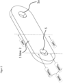
- a first measure is the offset of a section 12 of the link plate or links, preferably the middle section, in particular the outer link plate, in the direction of the chain center KM.
- the outer link Due to the interference fit between the bolt and the outer link, the outer link is also deformed by the bending of the bolt. The result is a bending of the outer link to the Chain center KM. This results in tensile stresses in the outer link plate on the side facing the chain center KM and compressive stresses on the side facing outwards. These stresses overlap with the tensile stresses within the link plate, which result from the chain tensile forces.
- a section 12 of the outer link plate is offset in the direction of the chain center axis KM.
- Such an inventive articulated chain is in Fig. 1b shown.
- the offset section 12 has a section center line 13 that runs parallel to the chain center axis KM. Furthermore, a line 14 is drawn through point 11, which should also run parallel to the section center line 13 or the chain center line KM. The vertical distance between the line 14 and the section center line 13 is marked with the reference symbol Y.
- the amount by which the above-mentioned offset should occur can be defined using the section center line 13 of the offset section 12 in relation to the point 11 of force transmission in the elastic deformation case already outlined above.
- the effect of reducing bending stresses in the outer link is greater the more precisely the section center line 13 of the offset section 12 passes through the force transmission point 11 or, in other words, the smaller the distance Y, the greater the effect of reducing bending stresses in the outer link.
- section center line 13 preferably passes exactly through the force transmission point 11 or at least approximately.
- the effect of the reduction is greater the closer the offset section can be brought to the chain joint, although the offset cannot of course be realized in the area of the link plate heads for geometric reasons.
- the chain tensile force of a articulated chain can also be increased by the following measure, in particular while maintaining or largely maintaining the other dimensioning parameters of the articulated chain, or at least the same chain tensile force can be achieved with reduced weight.
- the shape of a usual tab is in the Fig. 2 shown.
- the different cross-sections perpendicular to the chain alignment are also shown.
- the cross-sectional areas BMQ are significantly reduced.
- the middle area of the link plate on the other hand, has a considerably larger cross-sectional area LMQ.
- the aim is to adjust the cross-sectional areas BMQ and LMQ in such a way that approximately equal stress distributions are achieved.
- the contour of the tab can be designed as desired.
- a tapered shape of the tab is obtained.
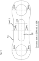
- the contour of the waist is marked with the reference number 21 and the removed areas are marked with the dot-dash line 22.
- the waist is designed in such a way that the Cross-sectional areas perpendicular to the chain pull direction approach the link in large areas.
- Fig. 2a A waisted outer flap is shown schematically in a top view.
- Fig. 2b is a cross section BMQ 1 and BMQ 2 according to section XX and in Fig.
- a cross-section LMQ according to section YY is shown.
- BMQ 1 + BMQ 2 should be equal to or approximately equal to LMQ.
- Q(L), with L in the longitudinal direction of the tab should be constant or approximately constant.
- the stress distribution within a tab wraps around the holes in the tab eyes. In the middle area of the tab, the stresses are distributed more evenly across the entire cross-section.
- the chain tensile force of a articulated chain can also be increased by the following measure, in particular while maintaining or largely maintaining the other dimensioning parameters of the articulated chain, or at least the same chain tensile force can be achieved with reduced weight.
- the breaking force can be increased for specified chain dimensions (bushing, pin diameter, link plate height, link plate thickness, link plate length, pitch).
- An inner link plate optimized in this way can, for example, Fig. 3 depicted contour.
- the area of reinforcement is marked with the reference number 31.
- the radius of the head area of such a tab can be defined as a function around the center of the hole via the angle ⁇ as a running coordinate.
- each link head segment S1 to S4 is equipped with one reinforcement 31 to 31c.
- the position and extent of the reinforcement can be described in more detail using the first reinforcement 31 on the first tab head segment S1.
- the reinforcement 31 is preferably arranged in the range of an angle ⁇ 1 of 20° to 50°, more preferably in the range between 25° and 40°, relative to the longitudinal axis L of the tab and the center point B of the bore 5 in or on the tab, in particular on the outside of the tab head segment S1.
- the tab longitudinal axis L accordingly defines the angle 0°.
- the bore wall cross section BMQ 1 between the inner link IL and the first link head segment S1 can be used.
- the bore wall cross section BMQ 1 should be arranged centrally and vertically above the bore. Based on this cross section, it is preferably provided that the cross section of the reinforced area, in each case radially starting from the respective bore center point B, should be 5% to 25%, preferably 10% to 18%, larger than the bore wall cross section BMQ 1 of the respective reinforced link head segment.
- the Cross-section Q r( ⁇ 1) of the reinforced wall should be 5% to 25%, preferably 10% to 18%, larger than the bore wall cross-section BMQ 1 .
- the chain tensile force of a link chain with at least one labyrinth seal in the area of the chain joint can also be increased by the following measure, in particular while maintaining or largely maintaining the other dimensioning parameters of the link chain, or at least the same chain tensile force can be achieved with reduced weight.
- labyrinths The penetration of dirt into the joint area of a chain can be delayed by labyrinths.
- labyrinths can be implemented in the form of additional components (e.g. lamellar sealing rings) or specially designed tabs (grooves and lugs in the area of the pitch holes) in combination with protruding bushings.
- additional components e.g. lamellar sealing rings
- tabs grooves and lugs in the area of the pitch holes
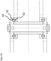
- the nose 41 and the groove 42 of the labyrinth seal on the plates be designed in such a way that corresponding overlaps are achieved in the chain tension direction.
- the at least one nose and groove are designed in a length or depth between 10% and 50% of the plate thickness, preferably in a range of 20% to 40% of the average tab thickness D of the respective tab.
- the respective tab refers to the tab in which the respective groove or nose is located.
- overlaps can also be created by additional elements.
- One possible example is a ring that is inserted into two grooves in the inner and outer link plate during assembly of the chain. Such an alternative is in the Fig. 4b shown.
- a labyrinth seal of a link chain between the inner and outer plates in an unloaded initial state is in the Fig. 4 shown.
- FIG. 4a An enlarged view is available in the Fig. 4a shown here.
- the corresponding gap dimensions and width of the nose BN or width of the groove BU are also shown here.
- the respective nose length LN and groove depth TN are also shown here.
- the width of the at least one nose and/or groove is designed in a thickness that is in the range of 80% to 120% of the nose length LN or groove depth TN.
- the corners and edges of the at least one nose and/or groove are each designed with identical radii or bevels, but at least approximately identical radii or bevels. This allows the load-bearing area to be increased.
- the radial clearance between the at least one groove and nose in the labyrinth is between 0.6 and 2.25mm. Based on a usual joint clearance between 0.4 and 1.5mm depending on the ambient conditions, the clearance between the groove and the nose in the labyrinth should be approximately 50% larger. This ensures that the labyrinths do not come into contact under normal operating force.
- the axial clearance can be set identically.
- different components (or component areas) in the chain strand can be relieved of load, for example the head area of the inner link plate, the head area of the outer link plate, the bolt in the shear area.
- Such constellations are shown from left to right in the figure Fig. 4c shown in the bottom row.
- the chain may need to be lengthened due to malfunctions, overload situations or other influences. These changes in length are distributed within the chain over those areas that have the least rigidity. If this load occurs repeatedly, there is a risk of material fatigue at these positions.
- the articulated chain in particular the inner plates and/or the outer plates, are designed to be as homogeneous as possible with regard to their rigidity in that the cross section perpendicular to the longitudinal axis L of the at least one inner plate 1 and/or the outer plate 2 along the longitudinal axis of the L of the plate deviates from one another by less than 20%, preferably less than 10%, and is more preferably identical.
- the cross-section LMQ can be adjusted accordingly by means of material recesses, which, for example, lead to a tapered or recessed tab.
- material recesses which, for example, lead to a tapered or recessed tab.
- the cross-section is then composed of the cross-sections LMQ 1 and LMQ 2 , for example in the case of a central opening.
- the stiffness can thus be adjusted using opening(s) in the middle tab areas. This design is to be used above all if, for certain reasons, circumstances, the outer contour of the tabs is fixed. This can, for example, result from a sliding transfer of forces via the tabs.
- FIG. 5a A joint chain that is as homogeneous as possible in terms of its stiffness is Fig. 5a shown. In the Fig. 5 corresponding cross-sections are indicated.
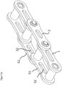
- a link chain according to the invention in which all the measures outlined above have been implemented, is in the Fig. 6 All measures suggested above can be carried out individually or in any combination on a link chain. They are also suitable for the inner link and/or the outer link of a link chain.
Landscapes
- Engineering & Computer Science (AREA)
- General Engineering & Computer Science (AREA)
- Mechanical Engineering (AREA)
- Devices For Conveying Motion By Means Of Endless Flexible Members (AREA)
- Chain Conveyers (AREA)
- Pivots And Pivotal Connections (AREA)
- Sealing Using Fluids, Sealing Without Contact, And Removal Of Oil (AREA)
- Sealing Devices (AREA)
Applications Claiming Priority (2)
| Application Number | Priority Date | Filing Date | Title |
|---|---|---|---|
| DE102017107870.3A DE102017107870A1 (de) | 2017-04-11 | 2017-04-11 | Gelenkkette |
| PCT/EP2018/059046 WO2018189118A1 (de) | 2017-04-11 | 2018-04-09 | Gelenkkette |
Publications (2)
| Publication Number | Publication Date |
|---|---|
| EP3610173A1 EP3610173A1 (de) | 2020-02-19 |
| EP3610173B1 true EP3610173B1 (de) | 2025-02-12 |
Family
ID=62027951
Family Applications (1)
| Application Number | Title | Priority Date | Filing Date |
|---|---|---|---|
| EP18719077.2A Active EP3610173B1 (de) | 2017-04-11 | 2018-04-09 | Gelenkkette |
Country Status (14)
| Country | Link |
|---|---|
| US (1) | US11525495B2 (ko) |
| EP (1) | EP3610173B1 (ko) |
| JP (1) | JP7136805B2 (ko) |
| KR (1) | KR102615357B1 (ko) |
| CN (1) | CN110494674B (ko) |
| AU (1) | AU2018250867B2 (ko) |
| CA (1) | CA3058052A1 (ko) |
| DE (1) | DE102017107870A1 (ko) |
| ES (1) | ES3015121T3 (ko) |
| FI (1) | FI3610173T3 (ko) |
| PL (1) | PL3610173T3 (ko) |
| RU (1) | RU2750945C2 (ko) |
| SA (1) | SA519410280B1 (ko) |
| WO (1) | WO2018189118A1 (ko) |
Families Citing this family (8)
| Publication number | Priority date | Publication date | Assignee | Title |
|---|---|---|---|---|
| DE102016000568A1 (de) * | 2016-01-20 | 2017-07-20 | Iwis Antriebssysteme Gmbh & Co. Kg | Aktuator mit einer rückensteifen Kette |
| DE102017107870A1 (de) | 2017-04-11 | 2018-10-11 | Ketten-Wulf Betriebs-Gmbh | Gelenkkette |
| TWI842753B (zh) * | 2019-03-27 | 2024-05-21 | 葡萄牙商米蘭達&艾爾茅公司 | 驅動鏈系統 |
| CN110242703B (zh) * | 2019-07-03 | 2024-08-09 | 杭州自强链传动有限公司 | 一种具有单向防弯功能的链条 |
| TWM585852U (zh) * | 2019-07-17 | 2019-11-01 | 岳盟企業股份有限公司 | 油封鏈條 |
| KR102147766B1 (ko) * | 2019-09-19 | 2020-08-25 | 강동관 | 체인 콘베어의 슬림형 체인 |
| TWI741728B (zh) * | 2020-08-10 | 2021-10-01 | 桂盟企業股份有限公司 | 鏈條及車輪傳動裝置 |
| TWI789792B (zh) * | 2021-06-21 | 2023-01-11 | 桂盟企業股份有限公司 | 油封鏈 |
Citations (13)
| Publication number | Priority date | Publication date | Assignee | Title |
|---|---|---|---|---|
| CN2146605Y (zh) | 1993-01-14 | 1993-11-17 | 岳盟企业股份有限公司 | 变速自行车链条 |
| CN2546688Y (zh) * | 2002-04-11 | 2003-04-23 | 桂盟企业股份有限公司 | 链条 |
| CN2644777Y (zh) | 2003-08-01 | 2004-09-29 | 桂盟企业股份有限公司 | 由三类组件组成的链条 |
| WO2005043005A1 (en) | 2003-10-30 | 2005-05-12 | F.S.A. S.R.L. | An articulated chain for drive transmission in bicycles |
| DE102004011572A1 (de) | 2004-03-10 | 2005-09-29 | Sram Deutschland Gmbh | Fahrradkette mit ausgebauchten Außen- und außen angefasten Innenlaschen |
| JP2006064049A (ja) | 2004-08-26 | 2006-03-09 | Enuma Chain Mfg Co Ltd | ローラチェーンのリンクプレート |
| DE102007009821A1 (de) | 2006-04-28 | 2007-10-31 | Tsubakimoto Chain Co. | Mehrreihige Kraftübertragungskette |
| JP2008164043A (ja) | 2006-12-27 | 2008-07-17 | Tsubakimoto Chain Co | 無給油チェーン |
| EP2339207A1 (en) | 2006-11-16 | 2011-06-29 | Shimano Inc. | Bicycle outer chain link plate |
| CN202646538U (zh) | 2012-05-31 | 2013-01-02 | 株式会社椿本链条 | 传动链条 |
| DE202012104764U1 (de) * | 2012-12-07 | 2013-01-30 | Thiele Gmbh & Co. Kg | Becherwerkskette mit Labyrinthdichtungen |
| CN203115099U (zh) | 2013-03-12 | 2013-08-07 | 洛阳轴研科技股份有限公司 | 一种油脂主轴密封结构 |
| CN204493582U (zh) | 2015-03-31 | 2015-07-22 | 天津市红利顺丰机械链条有限公司 | 链条单元 |
Family Cites Families (43)
| Publication number | Priority date | Publication date | Assignee | Title |
|---|---|---|---|---|
| DE187885C (ko) * | ||||
| GB280897A (en) * | 1926-11-19 | 1928-06-07 | Bbc Brown Boveri & Cie | Improvements in labyrinth packings |
| DE506899C (de) * | 1926-11-20 | 1930-09-13 | Bbc Brown Boveri & Cie | Labyrinthdichtung |
| SU66741A1 (ru) * | 1944-03-07 | 1945-11-30 | Н.К. Панцырев | Разъемна пластинчата цепь |
| GB880304A (en) | 1959-06-04 | 1961-10-18 | Donald Mayer King | Improvements in or relating to chains for use in conveyor systems |
| JPS551988Y2 (ko) * | 1975-12-29 | 1980-01-19 | ||
| JPS52168148U (ko) * | 1976-06-14 | 1977-12-20 | ||
| FR2396897A1 (fr) * | 1977-07-06 | 1979-02-02 | Sedis Transmissions Mec | Chaine de transmission |
| JPS5811674Y2 (ja) * | 1979-06-30 | 1983-03-04 | マエダ工業株式会社 | 自転車用チエ−ン |
| DE3308681A1 (de) * | 1983-03-11 | 1984-09-13 | Intertractor Viehmann GmbH & Co, 5820 Gevelsberg | Bolzen/buchsen-scharnier, insbesondere fuer gleisketten |
| DE3407169C2 (de) * | 1984-02-28 | 1986-01-23 | Kabelschlepp Gmbh, 5900 Siegen | Energieführungskette |
| JP2872676B2 (ja) * | 1988-08-03 | 1999-03-17 | 株式会社シマノ | 自転車用チェン |
| CH681909A5 (en) * | 1990-04-04 | 1993-06-15 | Fritz Wullschleger | Linked chain drive for telescoping column |
| GB2260592A (en) * | 1991-10-16 | 1993-04-21 | Stefan Karp | A chain |
| US5222920A (en) * | 1992-06-05 | 1993-06-29 | Rexnord Corporation | Chain including roller sealing arrangement |
| DE4241758C2 (de) * | 1992-12-11 | 1997-05-28 | Wulf Erich & Sohn | Büchsenförderkette |
| US5322483A (en) * | 1993-06-28 | 1994-06-21 | Yaban Chain Ind'l Co., Ltd. | Renovated bicycle chain |
| CN1179514A (zh) * | 1996-09-19 | 1998-04-22 | 萨克斯工业公司 | 传动链条尤其是自行车链条 |
| IT1292168B1 (it) * | 1997-06-16 | 1999-01-25 | Catene A Rullo Fratelli Fossat | Catena meccanica perfezionata |
| DE19918703B4 (de) * | 1999-04-26 | 2007-09-20 | KÖBO-KTB GmbH + Co. KG | Stahllaschenkette |
| US20050164816A1 (en) * | 2004-01-26 | 2005-07-28 | Wen-Pin Wang | Chain connecting device |
| US20060014600A1 (en) * | 2004-07-19 | 2006-01-19 | Daniel Wu | Lightweight drive chain |
| TW200833976A (en) * | 2007-01-31 | 2008-08-16 | Kmc Chain Ind Co Ltd | A bike chain with connector set |
| JP4956225B2 (ja) * | 2007-02-26 | 2012-06-20 | 株式会社江沼チヱン製作所 | ローラチェーンのリンクプレートの軽量化方法 |
| US7325391B1 (en) * | 2007-03-02 | 2008-02-05 | Shimano Inc. | Bicycle chain |
| DE202008004245U1 (de) | 2008-03-25 | 2008-06-05 | TIEN HSIN INDUSTRIES CO., LTD., Ta-Li City | Die verbesserte Konstruktion der Fahrradkette |
| US20110028255A1 (en) * | 2008-03-28 | 2011-02-03 | Chih-Chung Chin | Link Plate for a Bicycle Chain |
| RU2472049C2 (ru) * | 2009-01-22 | 2013-01-10 | Закрытое Акционерное Общество "Техмаш" | Цепь приводная пластинчатая, имеющая открытые шарниры качения с цилиндрической формой элемента зацепления |
| EP2538032A1 (de) * | 2011-06-22 | 2012-12-26 | Siemens Aktiengesellschaft | Radialbewegliches Dichtsystem für eine Gasturbine |
| CN103291842A (zh) * | 2012-02-24 | 2013-09-11 | 雅邦企业股份有限公司 | 含油链条及其链片 |
| US9574692B2 (en) * | 2012-07-26 | 2017-02-21 | Thomas & Betts International, Inc. | Conduit hub with wiper seal |
| JP6359803B2 (ja) * | 2013-03-27 | 2018-07-18 | 株式会社椿本チエイン | チェーン |
| ITRM20130247A1 (it) | 2013-04-24 | 2014-10-25 | Piaggio & C Spa | Circuito e metodo di controllo di una unita' d'illuminazione esterna a led di un veicolo |
| US9255624B2 (en) * | 2013-09-27 | 2016-02-09 | Shimano Inc. | Bicycle chain |
| CN203670609U (zh) * | 2013-12-18 | 2014-06-25 | 杭州自强链传动有限公司 | 一种用于高粉尘环境的链条 |
| DE202014105286U1 (de) * | 2014-11-04 | 2016-02-08 | Renold Gmbh | Rollenkette |
| CN105782348A (zh) * | 2014-12-24 | 2016-07-20 | 超汇桂盟传动(苏州)有限公司 | 链条的串接单元及链条的串接单元组 |
| JP2016217509A (ja) * | 2015-05-25 | 2016-12-22 | 株式会社椿本チエイン | チェーン及びリンクプレート |
| DE102016009814A1 (de) * | 2015-09-09 | 2017-03-09 | Sram Deutschland Gmbh | Rollenketten-Innenlasche |
| CN205101466U (zh) | 2015-11-24 | 2016-03-23 | 天津市强力链条有限公司 | 密封圈链条 |
| JP6035661B2 (ja) * | 2015-12-10 | 2016-11-30 | アクアインテック株式会社 | 伝動装置用チェーン |
| US9939045B2 (en) * | 2016-07-15 | 2018-04-10 | Shimano Inc. | Link plates for bicycle chain |
| DE102017107870A1 (de) | 2017-04-11 | 2018-10-11 | Ketten-Wulf Betriebs-Gmbh | Gelenkkette |
-
2017
- 2017-04-11 DE DE102017107870.3A patent/DE102017107870A1/de active Pending
-
2018
- 2018-04-09 PL PL18719077.2T patent/PL3610173T3/pl unknown
- 2018-04-09 KR KR1020197033153A patent/KR102615357B1/ko active Active
- 2018-04-09 CN CN201880024159.3A patent/CN110494674B/zh active Active
- 2018-04-09 AU AU2018250867A patent/AU2018250867B2/en active Active
- 2018-04-09 JP JP2019555937A patent/JP7136805B2/ja active Active
- 2018-04-09 CA CA3058052A patent/CA3058052A1/en active Pending
- 2018-04-09 WO PCT/EP2018/059046 patent/WO2018189118A1/de not_active Ceased
- 2018-04-09 RU RU2019135653A patent/RU2750945C2/ru active
- 2018-04-09 FI FIEP18719077.2T patent/FI3610173T3/fi active
- 2018-04-09 ES ES18719077T patent/ES3015121T3/es active Active
- 2018-04-09 EP EP18719077.2A patent/EP3610173B1/de active Active
-
2019
- 2019-09-20 US US16/577,866 patent/US11525495B2/en active Active
- 2019-10-09 SA SA519410280A patent/SA519410280B1/ar unknown
Patent Citations (13)
| Publication number | Priority date | Publication date | Assignee | Title |
|---|---|---|---|---|
| CN2146605Y (zh) | 1993-01-14 | 1993-11-17 | 岳盟企业股份有限公司 | 变速自行车链条 |
| CN2546688Y (zh) * | 2002-04-11 | 2003-04-23 | 桂盟企业股份有限公司 | 链条 |
| CN2644777Y (zh) | 2003-08-01 | 2004-09-29 | 桂盟企业股份有限公司 | 由三类组件组成的链条 |
| WO2005043005A1 (en) | 2003-10-30 | 2005-05-12 | F.S.A. S.R.L. | An articulated chain for drive transmission in bicycles |
| DE102004011572A1 (de) | 2004-03-10 | 2005-09-29 | Sram Deutschland Gmbh | Fahrradkette mit ausgebauchten Außen- und außen angefasten Innenlaschen |
| JP2006064049A (ja) | 2004-08-26 | 2006-03-09 | Enuma Chain Mfg Co Ltd | ローラチェーンのリンクプレート |
| DE102007009821A1 (de) | 2006-04-28 | 2007-10-31 | Tsubakimoto Chain Co. | Mehrreihige Kraftübertragungskette |
| EP2339207A1 (en) | 2006-11-16 | 2011-06-29 | Shimano Inc. | Bicycle outer chain link plate |
| JP2008164043A (ja) | 2006-12-27 | 2008-07-17 | Tsubakimoto Chain Co | 無給油チェーン |
| CN202646538U (zh) | 2012-05-31 | 2013-01-02 | 株式会社椿本链条 | 传动链条 |
| DE202012104764U1 (de) * | 2012-12-07 | 2013-01-30 | Thiele Gmbh & Co. Kg | Becherwerkskette mit Labyrinthdichtungen |
| CN203115099U (zh) | 2013-03-12 | 2013-08-07 | 洛阳轴研科技股份有限公司 | 一种油脂主轴密封结构 |
| CN204493582U (zh) | 2015-03-31 | 2015-07-22 | 天津市红利顺丰机械链条有限公司 | 链条单元 |
Non-Patent Citations (8)
| Title |
|---|
| ANONYMOUS: "Hinterschneidung", WIKIPEDIA, 19 October 2022 (2022-10-19), XP093337659, Retrieved from the Internet <URL:https://de.wikipedia.org/w/index.php?title=Hinterschneidung&oldid=227168885> |
| D20 - SACHVERSTANDIGENGUTACHTEN VERFASST AM: 11.10.2025 |
| D4 - BESTELLVORGANG KETTENSTRANGE AUS 2014/2015 ANGEBOT BIS SCHLUSSRECHNUNG: 12.05.2014 BIS 23.06.2015 |
| D5 - PACKLISTE VOM 19.05.2015 ZUM E4-BESTELLVORGANG LIEFERBELEG VOM 23.06.2015 ZUM E4-BESTELLVORGANG |
| D6 - Technische Zeichnungen zum E4-Bestellvorgang Erstellt am: 26.08.2013 |
| D7 - 42CRMO4 DATENBLATT VON SAARSTAHL ERSTELLT AM: 18.03.2016 (DATE?) |
| D8 - Sachverstandigengutachten Verfasst am: 13.03.2023 |
| THIELE GMBH -: "Thiele: Becherwerksketten", 7 November 2016 (2016-11-07), pages 1 - 20, XP093015435, Retrieved from the Internet <URL:https://www.thiele.de/fileadmin/user_upload/produkte/infoDownloads/THIELE_KATALOG_Becherwerksketten_DE.pdf> [retrieved on 20230118] * |
Also Published As
| Publication number | Publication date |
|---|---|
| CN110494674A (zh) | 2019-11-22 |
| BR112019020560A2 (pt) | 2020-04-28 |
| FI3610173T3 (fi) | 2025-03-24 |
| US11525495B2 (en) | 2022-12-13 |
| SA519410280B1 (ar) | 2023-06-27 |
| CA3058052A1 (en) | 2018-10-18 |
| CN110494674B (zh) | 2022-07-29 |
| EP3610173A1 (de) | 2020-02-19 |
| AU2018250867A1 (en) | 2019-10-17 |
| ES3015121T3 (en) | 2025-04-29 |
| RU2019135653A (ru) | 2021-05-11 |
| PL3610173T3 (pl) | 2025-05-12 |
| KR102615357B1 (ko) | 2023-12-20 |
| WO2018189118A1 (de) | 2018-10-18 |
| JP2020516827A (ja) | 2020-06-11 |
| KR20190134764A (ko) | 2019-12-04 |
| RU2019135653A3 (ko) | 2021-05-24 |
| US20200018378A1 (en) | 2020-01-16 |
| RU2750945C2 (ru) | 2021-07-06 |
| DE102017107870A1 (de) | 2018-10-11 |
| JP7136805B2 (ja) | 2022-09-13 |
| AU2018250867B2 (en) | 2024-05-02 |
Similar Documents
| Publication | Publication Date | Title |
|---|---|---|
| EP3610173B1 (de) | Gelenkkette | |
| EP2429882B1 (de) | Verbindungsvorrichtung | |
| EP2005025B1 (de) | Energieführungskette aus metall | |
| EP1927790A2 (de) | Kettenzahnrad | |
| DE102011008396A1 (de) | Kupplung zum dämpfenden Verbinden zweier Wellenabschnitte insbesondere einer Lenkwelle, sowie Lenkwelle und Verfahren zu Herstellung einer entsprechenden Kupplung | |
| DE112013004573B4 (de) | Kolbeneinheit eines Arbeitszylinders | |
| EP1178232B1 (de) | Flanschmitnehmer für ein Kardangelenk und Gelenkwelle | |
| EP2912343B1 (de) | Gelenkkette und gelenkkettenantrieb, insbesondere für stahlwasserbau und kettenbecherwerke | |
| WO2017041797A1 (de) | Hülse und zugehörige hülsenkette | |
| DE102014218323A1 (de) | Achseinheit | |
| EP3068679A1 (de) | Gummibandkettensegment | |
| EP3748190B1 (de) | Optimierte bolzenfügegeometrie | |
| EP4193068B1 (de) | Befestigungselement und einstellsystem umfassend ein befestigungselement | |
| AT500716B1 (de) | Verfahren zur ausgestaltung eines verbindungselementes und verbindungselement | |
| EP2944836B1 (de) | Wälzlager | |
| DE19845148A1 (de) | Anlasser | |
| DE102024204056B3 (de) | Tripodestern für ein Tripodegelenk | |
| DE102023210054B4 (de) | Passfeder zur Herstellung einer drehfesten Verbindung | |
| EP1683980B1 (de) | Flanschmitnehmer für ein Kardangelenk und Gelenkwelle | |
| WO2012136595A1 (de) | Bauteil für einen fahrzeugsitz | |
| EP3615841B1 (de) | Gelenkkette | |
| EP2673520B1 (de) | Elastische wellenkupplung und elastomersegment | |
| EP4647551A1 (de) | Fräswalze | |
| EP4495456A1 (de) | Zahnscheibe | |
| DE102010064733B4 (de) | Mehrfach-Ritzelanordnung für Fahrräder |
Legal Events
| Date | Code | Title | Description |
|---|---|---|---|
| STAA | Information on the status of an ep patent application or granted ep patent |
Free format text: STATUS: UNKNOWN |
|
| STAA | Information on the status of an ep patent application or granted ep patent |
Free format text: STATUS: THE INTERNATIONAL PUBLICATION HAS BEEN MADE |
|
| PUAI | Public reference made under article 153(3) epc to a published international application that has entered the european phase |
Free format text: ORIGINAL CODE: 0009012 |
|
| STAA | Information on the status of an ep patent application or granted ep patent |
Free format text: STATUS: REQUEST FOR EXAMINATION WAS MADE |
|
| 17P | Request for examination filed |
Effective date: 20191111 |
|
| AK | Designated contracting states |
Kind code of ref document: A1 Designated state(s): AL AT BE BG CH CY CZ DE DK EE ES FI FR GB GR HR HU IE IS IT LI LT LU LV MC MK MT NL NO PL PT RO RS SE SI SK SM TR |
|
| AX | Request for extension of the european patent |
Extension state: BA ME |
|
| RAP1 | Party data changed (applicant data changed or rights of an application transferred) |
Owner name: KETTENWULF BETRIEBS GMBH |
|
| DAV | Request for validation of the european patent (deleted) | ||
| DAX | Request for extension of the european patent (deleted) | ||
| STAA | Information on the status of an ep patent application or granted ep patent |
Free format text: STATUS: EXAMINATION IS IN PROGRESS |
|
| 17Q | First examination report despatched |
Effective date: 20210621 |
|
| TPAC | Observations filed by third parties |
Free format text: ORIGINAL CODE: EPIDOSNTIPA |
|
| TPAC | Observations filed by third parties |
Free format text: ORIGINAL CODE: EPIDOSNTIPA |
|
| TPAC | Observations filed by third parties |
Free format text: ORIGINAL CODE: EPIDOSNTIPA |
|
| TPAC | Observations filed by third parties |
Free format text: ORIGINAL CODE: EPIDOSNTIPA |
|
| GRAP | Despatch of communication of intention to grant a patent |
Free format text: ORIGINAL CODE: EPIDOSNIGR1 |
|
| STAA | Information on the status of an ep patent application or granted ep patent |
Free format text: STATUS: GRANT OF PATENT IS INTENDED |
|
| INTG | Intention to grant announced |
Effective date: 20241021 |
|
| TPAC | Observations filed by third parties |
Free format text: ORIGINAL CODE: EPIDOSNTIPA |
|
| TPAC | Observations filed by third parties |
Free format text: ORIGINAL CODE: EPIDOSNTIPA |
|
| GRAS | Grant fee paid |
Free format text: ORIGINAL CODE: EPIDOSNIGR3 |
|
| GRAA | (expected) grant |
Free format text: ORIGINAL CODE: 0009210 |
|
| STAA | Information on the status of an ep patent application or granted ep patent |
Free format text: STATUS: THE PATENT HAS BEEN GRANTED |
|
| AK | Designated contracting states |
Kind code of ref document: B1 Designated state(s): AL AT BE BG CH CY CZ DE DK EE ES FI FR GB GR HR HU IE IS IT LI LT LU LV MC MK MT NL NO PL PT RO RS SE SI SK SM TR |
|
| REG | Reference to a national code |
Ref country code: GB Ref legal event code: FG4D Free format text: NOT ENGLISH |
|
| REG | Reference to a national code |
Ref country code: CH Ref legal event code: EP |
|
| P01 | Opt-out of the competence of the unified patent court (upc) registered |
Free format text: CASE NUMBER: APP_3981/2025 Effective date: 20250124 |
|
| REG | Reference to a national code |
Ref country code: DE Ref legal event code: R096 Ref document number: 502018015554 Country of ref document: DE |
|
| REG | Reference to a national code |
Ref country code: IE Ref legal event code: FG4D Free format text: LANGUAGE OF EP DOCUMENT: GERMAN |
|
| REG | Reference to a national code |
Ref country code: FI Ref legal event code: FGE |
|
| REG | Reference to a national code |
Ref country code: ES Ref legal event code: FG2A Ref document number: 3015121 Country of ref document: ES Kind code of ref document: T3 Effective date: 20250429 |
|
| REG | Reference to a national code |
Ref country code: NL Ref legal event code: MP Effective date: 20250212 |
|
| PG25 | Lapsed in a contracting state [announced via postgrant information from national office to epo] |
Ref country code: RS Free format text: LAPSE BECAUSE OF FAILURE TO SUBMIT A TRANSLATION OF THE DESCRIPTION OR TO PAY THE FEE WITHIN THE PRESCRIBED TIME-LIMIT Effective date: 20250512 |
|
| PGFP | Annual fee paid to national office [announced via postgrant information from national office to epo] |
Ref country code: FI Payment date: 20250424 Year of fee payment: 8 |
|
| PGFP | Annual fee paid to national office [announced via postgrant information from national office to epo] |
Ref country code: DE Payment date: 20250430 Year of fee payment: 8 |
|
| PGFP | Annual fee paid to national office [announced via postgrant information from national office to epo] |
Ref country code: GB Payment date: 20250423 Year of fee payment: 8 Ref country code: ES Payment date: 20250530 Year of fee payment: 8 |
|
| REG | Reference to a national code |
Ref country code: LT Ref legal event code: MG9D |
|
| PG25 | Lapsed in a contracting state [announced via postgrant information from national office to epo] |
Ref country code: IS Free format text: LAPSE BECAUSE OF FAILURE TO SUBMIT A TRANSLATION OF THE DESCRIPTION OR TO PAY THE FEE WITHIN THE PRESCRIBED TIME-LIMIT Effective date: 20250612 Ref country code: NO Free format text: LAPSE BECAUSE OF FAILURE TO SUBMIT A TRANSLATION OF THE DESCRIPTION OR TO PAY THE FEE WITHIN THE PRESCRIBED TIME-LIMIT Effective date: 20250512 |
|
| PG25 | Lapsed in a contracting state [announced via postgrant information from national office to epo] |
Ref country code: NL Free format text: LAPSE BECAUSE OF FAILURE TO SUBMIT A TRANSLATION OF THE DESCRIPTION OR TO PAY THE FEE WITHIN THE PRESCRIBED TIME-LIMIT Effective date: 20250212 |
|
| PGFP | Annual fee paid to national office [announced via postgrant information from national office to epo] |
Ref country code: IT Payment date: 20250530 Year of fee payment: 8 |
|
| PG25 | Lapsed in a contracting state [announced via postgrant information from national office to epo] |
Ref country code: HR Free format text: LAPSE BECAUSE OF FAILURE TO SUBMIT A TRANSLATION OF THE DESCRIPTION OR TO PAY THE FEE WITHIN THE PRESCRIBED TIME-LIMIT Effective date: 20250212 |
|
| PG25 | Lapsed in a contracting state [announced via postgrant information from national office to epo] |
Ref country code: PT Free format text: LAPSE BECAUSE OF FAILURE TO SUBMIT A TRANSLATION OF THE DESCRIPTION OR TO PAY THE FEE WITHIN THE PRESCRIBED TIME-LIMIT Effective date: 20250612 Ref country code: LV Free format text: LAPSE BECAUSE OF FAILURE TO SUBMIT A TRANSLATION OF THE DESCRIPTION OR TO PAY THE FEE WITHIN THE PRESCRIBED TIME-LIMIT Effective date: 20250212 |
|
| PGFP | Annual fee paid to national office [announced via postgrant information from national office to epo] |
Ref country code: FR Payment date: 20250425 Year of fee payment: 8 |
|
| PG25 | Lapsed in a contracting state [announced via postgrant information from national office to epo] |
Ref country code: GR Free format text: LAPSE BECAUSE OF FAILURE TO SUBMIT A TRANSLATION OF THE DESCRIPTION OR TO PAY THE FEE WITHIN THE PRESCRIBED TIME-LIMIT Effective date: 20250513 Ref country code: BG Free format text: LAPSE BECAUSE OF FAILURE TO SUBMIT A TRANSLATION OF THE DESCRIPTION OR TO PAY THE FEE WITHIN THE PRESCRIBED TIME-LIMIT Effective date: 20250212 |
|
| PGFP | Annual fee paid to national office [announced via postgrant information from national office to epo] |
Ref country code: AT Payment date: 20250423 Year of fee payment: 8 |
|
| PGFP | Annual fee paid to national office [announced via postgrant information from national office to epo] |
Ref country code: TR Payment date: 20250505 Year of fee payment: 8 |
|
| PGFP | Annual fee paid to national office [announced via postgrant information from national office to epo] |
Ref country code: CZ Payment date: 20250403 Year of fee payment: 8 |
|
| PG25 | Lapsed in a contracting state [announced via postgrant information from national office to epo] |
Ref country code: SE Free format text: LAPSE BECAUSE OF FAILURE TO SUBMIT A TRANSLATION OF THE DESCRIPTION OR TO PAY THE FEE WITHIN THE PRESCRIBED TIME-LIMIT Effective date: 20250212 |
|
| PG25 | Lapsed in a contracting state [announced via postgrant information from national office to epo] |
Ref country code: SM Free format text: LAPSE BECAUSE OF FAILURE TO SUBMIT A TRANSLATION OF THE DESCRIPTION OR TO PAY THE FEE WITHIN THE PRESCRIBED TIME-LIMIT Effective date: 20250212 |
|
| PG25 | Lapsed in a contracting state [announced via postgrant information from national office to epo] |
Ref country code: DK Free format text: LAPSE BECAUSE OF FAILURE TO SUBMIT A TRANSLATION OF THE DESCRIPTION OR TO PAY THE FEE WITHIN THE PRESCRIBED TIME-LIMIT Effective date: 20250212 |
|
| PG25 | Lapsed in a contracting state [announced via postgrant information from national office to epo] |
Ref country code: EE Free format text: LAPSE BECAUSE OF FAILURE TO SUBMIT A TRANSLATION OF THE DESCRIPTION OR TO PAY THE FEE WITHIN THE PRESCRIBED TIME-LIMIT Effective date: 20250212 |
|
| PG25 | Lapsed in a contracting state [announced via postgrant information from national office to epo] |
Ref country code: RO Free format text: LAPSE BECAUSE OF FAILURE TO SUBMIT A TRANSLATION OF THE DESCRIPTION OR TO PAY THE FEE WITHIN THE PRESCRIBED TIME-LIMIT Effective date: 20250212 |
|
| PG25 | Lapsed in a contracting state [announced via postgrant information from national office to epo] |
Ref country code: SK Free format text: LAPSE BECAUSE OF FAILURE TO SUBMIT A TRANSLATION OF THE DESCRIPTION OR TO PAY THE FEE WITHIN THE PRESCRIBED TIME-LIMIT Effective date: 20250212 |
|
| REG | Reference to a national code |
Ref country code: DE Ref legal event code: R026 Ref document number: 502018015554 Country of ref document: DE |
|
| PLBI | Opposition filed |
Free format text: ORIGINAL CODE: 0009260 |
|
| REG | Reference to a national code |
Ref country code: CH Ref legal event code: L10 Free format text: ST27 STATUS EVENT CODE: U-0-0-L10-L00 (AS PROVIDED BY THE NATIONAL OFFICE) Effective date: 20251119 |
|
| PLAX | Notice of opposition and request to file observation + time limit sent |
Free format text: ORIGINAL CODE: EPIDOSNOBS2 |
|
| REG | Reference to a national code |
Ref country code: CH Ref legal event code: H13 Free format text: ST27 STATUS EVENT CODE: U-0-0-H10-H13 (AS PROVIDED BY THE NATIONAL OFFICE) Effective date: 20251125 |
|
| PG25 | Lapsed in a contracting state [announced via postgrant information from national office to epo] |
Ref country code: LU Free format text: LAPSE BECAUSE OF NON-PAYMENT OF DUE FEES Effective date: 20250409 |
|
| 26 | Opposition filed |
Opponent name: AUMUND FOERDERTECHNIK GMBH Effective date: 20251112 |
|
| PG25 | Lapsed in a contracting state [announced via postgrant information from national office to epo] |
Ref country code: MC Free format text: LAPSE BECAUSE OF FAILURE TO SUBMIT A TRANSLATION OF THE DESCRIPTION OR TO PAY THE FEE WITHIN THE PRESCRIBED TIME-LIMIT Effective date: 20250212 |
|
| REG | Reference to a national code |
Ref country code: BE Ref legal event code: MM Effective date: 20250430 |
|
| PG25 | Lapsed in a contracting state [announced via postgrant information from national office to epo] |
Ref country code: BE Free format text: LAPSE BECAUSE OF NON-PAYMENT OF DUE FEES Effective date: 20250430 |
|
| PG25 | Lapsed in a contracting state [announced via postgrant information from national office to epo] |
Ref country code: CH Free format text: LAPSE BECAUSE OF NON-PAYMENT OF DUE FEES Effective date: 20250430 |
|
| PLAB | Opposition data, opponent's data or that of the opponent's representative modified |
Free format text: ORIGINAL CODE: 0009299OPPO |
|
| REG | Reference to a national code |
Ref country code: CH Ref legal event code: L10 Free format text: ST27 STATUS EVENT CODE: U-0-0-L10-L00 (AS PROVIDED BY THE NATIONAL OFFICE) Effective date: 20260225 |
|
| PLBB | Reply of patent proprietor to notice(s) of opposition received |
Free format text: ORIGINAL CODE: EPIDOSNOBS3 |
|
| R26 | Opposition filed (corrected) |
Opponent name: AUMUND FOERDERTECHNIK GMBH Effective date: 20251112 |
|
| PG25 | Lapsed in a contracting state [announced via postgrant information from national office to epo] |
Ref country code: IE Free format text: LAPSE BECAUSE OF NON-PAYMENT OF DUE FEES Effective date: 20250409 |
|
| PGFP | Annual fee paid to national office [announced via postgrant information from national office to epo] |
Ref country code: PL Payment date: 20260327 Year of fee payment: 9 |