EP3610251B1 - Capteur de particules - Google Patents
Capteur de particules Download PDFInfo
- Publication number
- EP3610251B1 EP3610251B1 EP18717544.3A EP18717544A EP3610251B1 EP 3610251 B1 EP3610251 B1 EP 3610251B1 EP 18717544 A EP18717544 A EP 18717544A EP 3610251 B1 EP3610251 B1 EP 3610251B1
- Authority
- EP
- European Patent Office
- Prior art keywords
- protective sleeve
- exhaust gas
- inner protective
- gas
- gas inlet
- Prior art date
- Legal status (The legal status is an assumption and is not a legal conclusion. Google has not performed a legal analysis and makes no representation as to the accuracy of the status listed.)
- Active
Links
Images



Classifications
-
- G—PHYSICS
- G01—MEASURING; TESTING
- G01N—INVESTIGATING OR ANALYSING MATERIALS BY DETERMINING THEIR CHEMICAL OR PHYSICAL PROPERTIES
- G01N15/00—Investigating characteristics of particles; Investigating permeability, pore-volume or surface-area of porous materials
- G01N15/06—Investigating concentration of particle suspensions
- G01N15/0606—Investigating concentration of particle suspensions by collecting particles on a support
-
- G—PHYSICS
- G01—MEASURING; TESTING
- G01N—INVESTIGATING OR ANALYSING MATERIALS BY DETERMINING THEIR CHEMICAL OR PHYSICAL PROPERTIES
- G01N27/00—Investigating or analysing materials by the use of electric, electrochemical, or magnetic means
- G01N27/26—Investigating or analysing materials by the use of electric, electrochemical, or magnetic means by investigating electrochemical variables; by using electrolysis or electrophoresis
- G01N27/403—Cells and electrode assemblies
- G01N27/406—Cells and probes with solid electrolytes
- G01N27/407—Cells and probes with solid electrolytes for investigating or analysing gases
- G01N27/4077—Means for protecting the electrolyte or the electrodes
-
- F—MECHANICAL ENGINEERING; LIGHTING; HEATING; WEAPONS; BLASTING
- F01—MACHINES OR ENGINES IN GENERAL; ENGINE PLANTS IN GENERAL; STEAM ENGINES
- F01N—GAS-FLOW SILENCERS OR EXHAUST APPARATUS FOR MACHINES OR ENGINES IN GENERAL; GAS-FLOW SILENCERS OR EXHAUST APPARATUS FOR INTERNAL-COMBUSTION ENGINES
- F01N11/00—Monitoring or diagnostic devices for exhaust-gas treatment apparatus
-
- G—PHYSICS
- G01—MEASURING; TESTING
- G01N—INVESTIGATING OR ANALYSING MATERIALS BY DETERMINING THEIR CHEMICAL OR PHYSICAL PROPERTIES
- G01N11/00—Investigating flow properties of materials, e.g. viscosity, plasticity; Analysing materials by determining flow properties
-
- G—PHYSICS
- G01—MEASURING; TESTING
- G01N—INVESTIGATING OR ANALYSING MATERIALS BY DETERMINING THEIR CHEMICAL OR PHYSICAL PROPERTIES
- G01N15/00—Investigating characteristics of particles; Investigating permeability, pore-volume or surface-area of porous materials
- G01N15/06—Investigating concentration of particle suspensions
- G01N15/0656—Investigating concentration of particle suspensions using electric, e.g. electrostatic methods or magnetic methods
-
- G—PHYSICS
- G01—MEASURING; TESTING
- G01N—INVESTIGATING OR ANALYSING MATERIALS BY DETERMINING THEIR CHEMICAL OR PHYSICAL PROPERTIES
- G01N27/00—Investigating or analysing materials by the use of electric, electrochemical, or magnetic means
- G01N27/02—Investigating or analysing materials by the use of electric, electrochemical, or magnetic means by investigating impedance
- G01N27/04—Investigating or analysing materials by the use of electric, electrochemical, or magnetic means by investigating impedance by investigating resistance
- G01N27/06—Investigating or analysing materials by the use of electric, electrochemical, or magnetic means by investigating impedance by investigating resistance of a liquid
- G01N27/07—Construction of measuring vessels; Electrodes therefor
-
- F—MECHANICAL ENGINEERING; LIGHTING; HEATING; WEAPONS; BLASTING
- F01—MACHINES OR ENGINES IN GENERAL; ENGINE PLANTS IN GENERAL; STEAM ENGINES
- F01N—GAS-FLOW SILENCERS OR EXHAUST APPARATUS FOR MACHINES OR ENGINES IN GENERAL; GAS-FLOW SILENCERS OR EXHAUST APPARATUS FOR INTERNAL-COMBUSTION ENGINES
- F01N2560/00—Exhaust systems with means for detecting or measuring exhaust gas components or characteristics
- F01N2560/02—Exhaust systems with means for detecting or measuring exhaust gas components or characteristics the means being an exhaust gas sensor
-
- F—MECHANICAL ENGINEERING; LIGHTING; HEATING; WEAPONS; BLASTING
- F01—MACHINES OR ENGINES IN GENERAL; ENGINE PLANTS IN GENERAL; STEAM ENGINES
- F01N—GAS-FLOW SILENCERS OR EXHAUST APPARATUS FOR MACHINES OR ENGINES IN GENERAL; GAS-FLOW SILENCERS OR EXHAUST APPARATUS FOR INTERNAL-COMBUSTION ENGINES
- F01N2560/00—Exhaust systems with means for detecting or measuring exhaust gas components or characteristics
- F01N2560/05—Exhaust systems with means for detecting or measuring exhaust gas components or characteristics the means being a particulate sensor
-
- G—PHYSICS
- G01—MEASURING; TESTING
- G01N—INVESTIGATING OR ANALYSING MATERIALS BY DETERMINING THEIR CHEMICAL OR PHYSICAL PROPERTIES
- G01N15/00—Investigating characteristics of particles; Investigating permeability, pore-volume or surface-area of porous materials
- G01N2015/0042—Investigating dispersion of solids
- G01N2015/0046—Investigating dispersion of solids in gas, e.g. smoke
-
- Y—GENERAL TAGGING OF NEW TECHNOLOGICAL DEVELOPMENTS; GENERAL TAGGING OF CROSS-SECTIONAL TECHNOLOGIES SPANNING OVER SEVERAL SECTIONS OF THE IPC; TECHNICAL SUBJECTS COVERED BY FORMER USPC CROSS-REFERENCE ART COLLECTIONS [XRACs] AND DIGESTS
- Y02—TECHNOLOGIES OR APPLICATIONS FOR MITIGATION OR ADAPTATION AGAINST CLIMATE CHANGE
- Y02T—CLIMATE CHANGE MITIGATION TECHNOLOGIES RELATED TO TRANSPORTATION
- Y02T10/00—Road transport of goods or passengers
- Y02T10/10—Internal combustion engine [ICE] based vehicles
- Y02T10/40—Engine management systems
Definitions
- an exhaust gas sensor which comprises a sleeve-shaped sensor housing, a sensor element fixed in the sensor housing, which protrudes beyond the sensor housing on the exhaust side, and a sleeve-shaped protective tube which is attached to the sensor housing on the exhaust side, the protective tube consisting of an inner protective sleeve and an outer protective sleeve exists, wherein the inner protective sleeve surrounds an exhaust-side end region of the sensor element, wherein the outer protective sleeve surrounds the inner protective sleeve at least in some areas, so that an annular space is formed between the outer protective sleeve and the inner protective sleeve, the outer protective sleeve and the inner protective sleeve each having a gas outlet and a Have gas inlet and a flow through the protective tube from the gas inlet of the outer protective sleeve into the annular space, from there through the gas inlet of the inner protective sleeve into the
- the DE 10 2016 102 597 A1 discloses a system for detecting particulate matter in an exhaust system of a vehicle comprising a first outer tube having a plurality of suction openings on an upstream surface and a second inner tube having a plurality of suction openings on a downstream surface, and a particulate matter sensor located within the second inner tube is positioned.
- the present invention relates to an exhaust gas sensor as defined in claim 1. Preferred features of the exhaust gas sensor are described in the dependent claims. A use of the exhaust gas sensor is defined in claim 10. This is a particle sensor for detecting the concentration of solid components of a gas, for example the concentration of soot in an exhaust gas from an internal combustion engine.
- the present invention is based on the knowledge that the sensitivity and dynamics of the exhaust gas sensor is fundamentally influenced by its orientation in an exhaust gas line, in particular with regard to the rotation of the exhaust gas sensor about its longitudinal axis, which is preferably oriented perpendicular to the main flow direction in the exhaust gas line is. It was recognized that, for example, in the exhaust gas sensor known from the prior art, exhaust gas preferably enters the interior of the protective tube through the upstream gas inlet openings of the inner and outer protective sleeve and the sensor element preferably flows in a directed direction from these gas inlet openings.
- exhaust gas preferably enters the interior of the protective tube through the downstream gas inlet openings of the inner and outer protective sleeve and the sensor element preferably flows in a directed direction from these gas inlet openings.
- these sensors result in different sensitivity and dynamics of the exhaust gas sensor.
- the accuracy of the exhaust gas sensor when mounted in an undefined oriented manner in an exhaust pipe, in particular when the exhaust gas sensor is rotated in an undefined manner about its longitudinal axis, is increased in this way.
- the present invention is therefore also based on the inventors' knowledge that soot particles contained in the exhaust gas can be deposited on the sensor element particularly efficiently if the exhaust gas is directed at the sensor element with the highest possible flow speed. A high proportion of the soot particles contained in the exhaust gas reach very close to the sensor element and are deposited on it at a high rate.
- the flow speed at which the exhaust gas is directed towards the sensor element can be increased to an adequate extent by the gas inlet of the inner protective sleeve forming the smallest flow cross section when flowing through the protective tube, in particular if the gas inlet is on an axial direction Height of the sensor element is arranged.
- the throttling effect of the gas inlet of the inner protective tube that is realized in this way maximizes a pressure difference between the interior of the inner protective sleeve and the annular space, which gives the exhaust gas a significant acceleration in the direction of the sensor element.
- the present invention can particularly increase the sensitivity of a particle sensor.
- the exhaust gas sensor has a sleeve-shaped sensor housing, which in particular has a through hole and in this respect defines in particular an axis or longitudinal axis and an axial direction within the scope of the invention.
- an orientation of this axis or this axial direction is referred to as the exhaust side.
- the sleeve-shaped sensor housing can be metallic, for example.
- the sleeve-shaped sensor housing can, for example, have an external thread and/or an external hexagon profile.
- the exhaust gas sensor can be mounted in particular in this or in particular in another way in an exhaust pipe, in particular of an internal combustion engine.
- a sensor element is fixed in the sensor housing.
- the sensor element is in particular at least partially fixed in the through hole of the sensor housing.
- the sensor element protrudes beyond the sensor housing on the exhaust side. It is provided that a sensitive area of the sensor element, a known interdigital electrode structure, is arranged on the part of the sensor element that protrudes beyond the sensor housing on the exhaust side.
- the exhaust gas sensor according to the invention has a sleeve-shaped protective tube which is attached to the sensor housing on the exhaust side, for example welded.
- the protective tube can, for example, be welded from the radial outside to a collar of the sensor housing.
- the protective tube can, for example, be metallic; for example, it can be composed of several deep-drawn parts.
- the protective tube consists of two protective sleeves, an inner protective sleeve and an outer protective sleeve.
- the exhaust gas sensor can have a further protective sleeve, which interacts in particular with the protective tube and/or the inner protective sleeve and the outer protective sleeve, for example at least partially surrounding them.
- the inner protective sleeve and the outer protective sleeve each have the basic shape of a sleeve. In particular, there is at least one passage in an axial direction of the respective sleeve.
- the inner protective sleeve and the outer protective sleeve each individually and/or as a whole, have a basic shape that is essentially rotationally symmetrical.
- the Sleeve-shaped housings, the inner protective sleeve and/or the outer protective sleeve and in particular also the sensor element can, for example, be arranged coaxially to one another with respect to their basic structure.
- the inner protective sleeve is particularly attached to the sensor housing on the exhaust side, for example welded.
- the inner protective sleeve surrounds an exhaust-side end region of the sensor element, for example an exhaust-side end region of the sensor element, on which a sensitive region of the sensor element, in particular the sensitive region already explained above, is arranged.
- the outer protective sleeve is fastened, in particular on the exhaust side, to the sensor housing, for example welded, for example together with the inner protective sleeve by a single circumferential weld seam.
- the outer protective sleeve surrounds the inner protective sleeve at least in some areas.
- at least parts of the outer protective sleeve are arranged radially and/or axially outside the exhaust gas side, in particular on the opposite side as seen from the sensor element, of the inner protective sleeve.
- the outer protective sleeve only accommodates a part of the inner protective sleeve close to the housing in its interior, while the inner protective sleeve penetrates the outer protective sleeve and projects beyond it axially in the exhaust gas direction.
- outer protective sleeve and the inner protective sleeve are arranged both radially and axially outside the inner protective sleeve, in particular on the opposite side as seen from the sensor element.
- annular space is formed between the outer protective sleeve and the inner protective sleeve.
- An annular space is understood to mean, in particular, a space between two, in particular concentric, at least partially nested sleeves, for example cylinders. It can for example, a hollow cylindrical space.
- the projection of the annular space in the axial direction is an annular surface, which is delimited in particular by two concentric circles.
- the radii of the concentric circles can form a ratio that is between 0.35 and 0.7.
- the outer protective sleeve and the inner protective sleeve each have a gas outlet and a gas inlet.
- a gas inlet of the outer protective sleeve and a gas inlet of the inner protective sleeve and a gas outlet of the outer protective sleeve and a gas outlet of the inner protective sleeve are provided.
- Such a gas inlet or such a gas outlet of the protective sleeve in question can in particular be at least one opening in the protective sleeve in question, i.e. exactly one opening or a plurality of openings in each case, the opening or openings in particular allowing a macroscopic gas passage from the one outside of the sleeve in question represent an inside of the sleeve in question.
- these openings parallel to one another, allow a macroscopic passage of gas from an outside of the sleeve in question to an inside of the sleeve in question.
- the openings can fundamentally point in any direction, for example in the axial direction or in the radial direction.
- the gas inlet of the outer protective sleeve can, for example, consist of a large number of openings arranged regularly along the circumference of the outer protective sleeve.
- the gas inlet of the inner protective sleeve can, for example, consist of a large number of openings arranged regularly along the circumference of the inner protective sleeve.
- the gas outlet of the outer protective sleeve can, for example, consist of a central opening on the exhaust gas side.
- the gas outlet of the inner protective sleeve can, for example, consist of a central exhaust-side opening or consist of a plurality of openings which are arranged on an exhaust-side bottom of the inner protective sleeve, also known as a baffle plate.
- gas inlets and gas outlets are assigned flow cross sections. In the case of a single opening this is the geometric cross section of the opening, in the case of several openings this is the sum of the geometric cross sections of the openings in question.
- the openings in the protective sleeves are assigned to gas inlets and gas outlets.
- “Mandatory” means in particular that flow in a different order or via other paths is constructively excluded.
- the annular space communicates directly with an area outside the outer protective sleeve only via the gas inlet of the outer protective sleeve and / or the annular space communicates directly with the interior of the inner protective sleeve only via the gas inlet of the inner protective sleeve and / or that the interior of the inner protective sleeve communicates with an area outside the exhaust gas sensor through the gas outlets of the outer and inner protective sleeves, without first communicating again with the annular space.
- the flow through the protective tube takes place with regard to the gas inlets and gas outlets, i.e. apart from the parallel passage through several openings belonging to a gas inlet and a gas outlet, due to the structure of the protective tube, in particular only in the sequence defined in this way on a particularly linear and especially unbranched path.
- the flow through the protective tube can in particular be driven by this be that the gas outlet of the inner or outer protective sleeve is arranged on the exhaust side of the gas inlet of the outer protective sleeve, i.e., in particular when installing the exhaust gas sensor on the wall of an exhaust pipe, at a location with lower static pressure.
- the flow influence by the exhaust gas sensor itself, in particular by the protective tube itself, in particular a braking of the flow in the area of the gas inlet of the outer protective sleeve can also bring about or intensify this effect.
- the gas inlet of the inner protective sleeve is arranged in particular at the axial height of the sensor element.
- the gas inlet of the inner protective sleeve can be arranged at the axial height of a sensitive area of the sensor element, in particular the sensitive area already explained above.
- there is a significant acceleration of the exhaust gas in the direction of the sensor element for example, in the case of a particle sensor mentioned, the deposition of particles on the sensor element and thus the sensitivity of the particle sensor increase, as explained above.
- the gas inlet of the inner protective sleeve can be arranged in particular on the axial side facing away from the exhaust gas of a sensitive area of the sensor element, in particular the sensitive area already explained above.
- the gas flowing into the interior of the inner protective sleeve is directed by a deflection element or several deflection elements onto a sensitive area of the sensor element, in particular onto the sensitive area already explained above.
- the gas inlet of the inner protective sleeve forms the smallest flow cross section when flowing through the protective tube.
- the flow cross section of the gas inlet is therefore smaller than all others in the Cross sections flowed through the protective tube, in particular each smaller than the flow cross section of the gas outlet of the outer protective sleeve, the flow cross section of the gas inlet of the outer protective sleeve and the flow cross section of the gas outlet of the inner protective sleeve.
- the flow cross section of the gas inlet is therefore also smaller than a flow cross section assigned to the annular space and the interior of the inner protective sleeve and any end space (see below).
- the gas inlet of the inner protective sleeve has a flow cross section which is 10% to 95%, in particular 25% to 50% or 50% to 80%, of the flow cross section of the gas outlet of the inner protective sleeve, and / or 10% to 95%, in particular 25% to 50% or 50% to 80%, of the flow cross section of the gas outlet of the outer protective sleeve.
- the first group is characterized in that the gas outlet of the outer protective sleeve has at least one gas outlet opening in which the inner protective sleeve is fixed and through which the inner protective sleeve protrudes beyond the outer protective sleeve on the exhaust side, and the gas outlet of the inner protective sleeve reaches the interior of the inner one Protective sleeve directly connects to an area outside the exhaust gas sensor.
- the flow passes, in particular, from the interior of the inner protective sleeve directly into the area outside the exhaust gas sensor, without being guided again by the outer protective sleeve.
- the gas outlet opening of the outer protective sleeve no longer comes into direct contact with the flow; it merely accommodates the inner protective sleeve, in which the flow moves towards the gas outlet of the inner protective tube; It is nevertheless a gas outlet opening and a gas outlet from the outer protective sleeve in the sense of the invention.
- the second group is characterized by the fact that the outer protective sleeve protrudes axially in the direction of the exhaust gas side over the inner protective sleeve and between the outer protective sleeve and the inner protective sleeve, an end space separate from the annular space is formed, and the gas outlet of the inner protective sleeve connects the interior of the inner protective sleeve with the end space and the gas outlet of the outer protective sleeve connects the end space with an area outside the exhaust gas sensor.
- the flow When flowing through the protective tube, the flow, in particular from the interior of the inner protective sleeve, first passes through the gas outlet of the inner protective sleeve into the end space separate from the annular space and from there reaches an area outside the exhaust gas sensor, in particular via the outlet opening of the outer protective sleeve.
- the inner protective sleeve can be largely open on the exhaust side, so that the gas outlet of the inner protective sleeve consists of a central opening with a maximum cross-sectional area.
- the inner protective sleeve can be closed on the exhaust side by a baffle plate which has one or more openings, in particular has a plurality of openings arranged off-center on a ring.
- the gas inlet of the outer protective sleeve has at least one gas inlet opening which is provided with at least one swirl element, for example a plurality of openings arranged at regular intervals on the circumference of the outer protective sleeve, each of which is provided with a swirl element is.
- the exhaust gas entering the annular space is deflected by the swirl element or elements in such a way that it rotates around the inner protective sleeve within the annular space.
- Such a development has the advantage that the function of the exhaust gas sensor, in particular its sensitivity, becomes even more largely independent of the angular position in which the exhaust gas sensor is mounted in an exhaust gas flow (in particular at which angle of rotation about its longitudinal axis) and furthermore becomes largely independent of it which angular position the inner and outer protective sleeves are installed relative to each other, even if the gas inlet of the inner protective sleeve only has openings that are not evenly distributed over its circumference.
- the gas inlet of the inner protective sleeve has at least one gas inlet opening has at least one deflection element which deflects an exhaust gas entering the annular space in the direction of the gas outlet of the inner protective sleeve.
- the gas inlet of the inner protective sleeve can have a plurality of gas inlet openings which are arranged at regular intervals on the circumference of the inner protective sleeve and which each have a deflection element which deflects an exhaust gas entering the annular space in the direction of the gas outlet of the inner protective sleeve .
- the gas inlet of the inner protective sleeve consists of a large number of openings that are very small. For example, at least 10 or even at least 30 openings can be provided, with the cross-sectional area of a single one of these openings not being more than 1 mm 2 or even not more than 0.3 mm 2 .
- the openings can, for example, be arranged next to one another at regular intervals on the circumference of the inner protective sleeve or in two, three, four or more circumferential rings.
- the advantage compared to larger openings is that the sensor element is better protected against condensate or foreign particles (e.g. metal particles).
- the minimum size of the openings results from the fact that the gas inlet of the inner protective tube should not become blocked even in the presence of soot in the exhaust gas.
- the cross-sectional area of each opening should not be smaller than 0.06mm 2 .
- each individual gas inlet opening of the inner protective sleeve has a flow cross section whose square root is smaller than 1/18 or even smaller than 1/25 of the longitudinal extent of the protective tube and/or smaller than 1/35 or even smaller than 1/ 25 the longitudinal extent of the Sensor element is.
- the sensitivity of the exhaust gas sensor can be significantly increased by the fact that the gas inlet of the inner protective tube and a sensitive area of the sensor element, for example the sensitive area explained above, are aligned with one another, in particular lying opposite one another, because in this case the gas flows into the interior of the inner Exhaust gas entering the protective sleeve always directly contacts the sensitive area.
- this can be done by arranging the sensitive area only on a radial and/or axial partial area of the sensor element, and the gas inlet of the inner protective sleeve is arranged only on a radial and/or axial partial area of the inner protective sleeve and the sensitive area and the Gas inlet of the inner protective sleeve opposite each other
- the sensor element is designed as a planar sensor element and the sensitive area is arranged only on part of a side surface of the sensor element, and the gas inlet of the inner protective sleeve is arranged only on a radial and / or axial partial area of the inner protective sleeve and the sensitive area and the gas inlet of the inner protective sleeve are opposite each other.
- the gas inlet of the inner protective sleeve can consist of a large number of openings which are arranged one above the other in the axial direction, in particular only in one row or only in two rows.
- Negative gradients of the static pressure in the exhaust gas pointing in the axial direction occur in an exhaust pipe of an internal combustion engine, for example, when the exhaust gas sensor is in the exhaust pipe is mounted so that a cross section of the exhaust pipe has a more central region and a more peripheral region, with a flow velocity of the exhaust gas in the exhaust pipe being fundamentally higher in the more central region than in the more peripheral region and with the gas inlet of the outer protective sleeve in the more peripheral region Area is arranged and the gas outlet of the inner or outer protective sleeve is arranged in the more central area, since in this case the static pressure is locally lower, the higher the flow velocity.
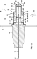
- the Figure 1a shows a cross section along the longitudinal axis LA of the exhaust gas sensor 1 according to a first exemplary embodiment.
- the exhaust gas sensor 1 has a sleeve-shaped sensor housing 12, in whose through hole a ceramic sensor element 14 is fixed.
- the ceramic sensor element 14 projects both on the side of the sensor housing 12 facing the exhaust gas (in Figure 1a right) as well as on the side of the sensor housing 12 facing away from the exhaust gas (in Figure 1a left) beyond sensor housing 12.
- a sleeve-shaped, metallic protective tube 20 is welded to a circumferential collar 121 of the sensor housing 12 pointing in the exhaust gas direction.
- the protective tube 20 consists of an inner protective sleeve 21 and an outer protective sleeve 22.
- the inner protective sleeve 21 surrounds an exhaust-side end region 141 of the sensor element 14 with a radial and axial distance.
- the outer protective sleeve 22 surrounds the inner protective sleeve 21 in such a way that it rests on the inner protective tube 21 at the axial height of the collar 121 and is welded together with this to the collar 121 by means of a circumferential weld seam, and also on the exhaust side of the collar 121 between the outer protective sleeve 22 and inner protective sleeve 21 an annular space 30 is formed, that a contact area 31 is also formed on the exhaust side of the annular space 30, in which the inner protective sleeve 21 with its outer surface fully rests on the inner surface of the outer protective sleeve 22 and that furthermore on the exhaust side of the contact area 31 End space 32 is formed, which is delimited radially by the outer protective sleeve 22, is delimited on the side facing away from the exhaust gas by a bottom 211 of the inner protective sleeve 21 designed as a baffle plate and delimited on the side facing the exhaust gas by a bottom 221 of the outer protective slee
- the outer protective sleeve 22 has, for example, eight gas inlet openings 222, which are arranged at equal distances along the circumference of the outer protective sleeve 22 at the axial height of an end region 301 of the annular space 30 facing the exhaust gas.
- the gas inlet openings 222 each have a swirl element 223, which is designed as a swirl flap and gives the gas flowing into the annular space 30 an impulse directed towards the sensor housing 12 and an angular momentum directed in the direction of the longitudinal axis LA of the sensor, so that the exhaust gas within the annular space 30 rotates around the inner protective sleeve 21.
- swirl elements 223 can be dispensed with.
- the outer protective sleeve 22 also has a relatively large one on the bottom 221 Gas outlet opening 224.
- the gas outlet opening 224 can even be enlarged in such a way that the bottom 221 is completely or largely eliminated.
- the inner protective sleeve 21 has, for example, 32 comparatively small gas inlet openings 212, which are arranged at equal distances along the circumference of the inner protective sleeve 21 in two rows at the axial height of an approximately central region 302 of the annular space 30 in the axial direction.
- the gas inlet openings 212 are also arranged at the axial height of the sensor element 14.
- the gas inlet openings 212 are arranged at the axial height of a sensitive area of the sensor element 14.
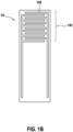
- the sensitive area of the sensor element 14 is, for example, an interdigital electrode structure 142 (see also Fig. 1b ), in this respect the exhaust gas sensor is a particle sensor for detecting soot in the exhaust gas of an internal combustion engine.
- the sensitive area could also be an electrode of an electrochemical cell and/or an opening leading into the interior of the sensor element, for example of a broadband lambda probe or a NOx sensor.
- the inner protective sleeve 21 has a ring of eight off-center gas outlet openings 213 on its base 211.
- a further central gas outlet opening 213 is provided on the bottom 211 of the inner protective sleeve 21. In one variant, the latter can also be omitted.
- the 32 gas inlet openings 212 of the inner protective sleeve 21 are circular in the example and have a diameter of 0.5mm.
- the flow cross section of the gas inlet of the inner protective sleeve is therefore 6mm 2 .
- the flow cross section of the gas outlet of the inner protective sleeve 21 is 10mm 2 in the example.
- the flow cross section of the gas outlet of the outer protective sleeve 22 is 14mm 2 in the example.
- the flow cross section of the gas inlet of the outer protective sleeve 22 is 10mm 2 in the example.
- the length of the sensor element 14 is approximately 55mm, the longitudinal extent of the protective tube 20 is approximately 28mm.
- the gas inlet of the inner protective sleeve 21 thus forms the smallest flow cross section when flowing through the protective tube 20, which results in the positive effects explained at the beginning.
- the diameter of the gas inlet openings 212 of the inner protective sleeve 21 can be reduced to 0.4mm or even to 0.3mm. In alternatives to this, only eight, in particular circular, gas inlet openings 212 of the inner protective sleeve 21 can be provided, the diameter of which is 1 mm or 0.8 mm or 0.6 mm and which are arranged in a row evenly along the circumference of the inner protective tube 21.
- the Figure 1b shows a top view of the sensor element 14 in the perspective from bottom to top in the Figure 1a .
- the sensor element 14 is designed to be planar and an interdigital electrode structure 142 is arranged on the surface of the sensor element 14 in an exhaust-side end region 141, which forms the sensitive region of the sensor element 14.
- the exhaust gas sensor 1 can be mounted in the wall 51 of an exhaust pipe 50 of an internal combustion engine in such a way that, as seen in a cross section of the exhaust pipe 50, the gas inlet of the outer protective sleeve 22 is arranged in an edge region 52 of the exhaust pipe, while the gas outlet of the outer protective sleeve 22 is in a central one Area 53 of the exhaust pipe is arranged, see Figure 1a .
- Exhaust gas flows through the exhaust pipe 50 essentially perpendicular to the longitudinal axis LA of the exhaust gas sensor 1, parallel to the plane of the drawing Figure 1a , in the direction of the double arrow 100.
- the exhaust gas then passes through the gas outlet openings 213 of the inner protective sleeve 21 into the end space 32 and from there through the gas outlet opening 224 of the outer protective sleeve 22.
- This flow is in the Figure 1a indicated by arrow line 101.
- the Figure 2 shows a cross section along the longitudinal axis LA of the exhaust gas sensor 1 according to a second exemplary embodiment.
- the exhaust gas sensor 1 has a sleeve-shaped sensor housing 12, in whose through hole a ceramic sensor element 14 is fixed.
- the ceramic sensor element 14 projects both on the side of the sensor housing 12 facing the exhaust gas (in Figure 2 right) as well as on the side of the sensor housing 12 facing away from the exhaust gas (in Figure 2 left) beyond the sensor housing 12.
- a sleeve-shaped, metallic protective tube 20 is welded to a circumferential collar 121 of the sensor housing 12 pointing in the exhaust gas direction.
- the protective tube 20 consists of an inner protective sleeve 21 and an outer protective sleeve 22.
- the inner protective sleeve 21 surrounds an exhaust-side end region 141 of the sensor element 14 with a radial and axial distance.
- the outer protective sleeve 22 surrounds the inner protective sleeve 21 in such a way that it rests on the inner protective tube 21 at the axial height of the collar 121 and is welded together with this to the collar 121 by means of a circumferential weld and that furthermore on the exhaust side of the collar 121 between the outer protective sleeve 22 and inner protective sleeve 21 an annular space 30 is formed.
- the outer protective sleeve 22 On the exhaust side of the annular space 30, the outer protective sleeve 22 has a relatively large central gas outlet opening 224, in which the inner protective sleeve 21 is fixed and through which the inner protective sleeve 21 protrudes on the exhaust side over the outer protective sleeve 22 in a projection area 33.
- the inner protective sleeve 21 is fixed, in particular pressed, in the gas outlet opening 224 of the outer protective sleeve 22 without any gaps, i.e. tightly.
- the projection area 33 ends on the exhaust side with a base 211 of the inner protective sleeve 21.
- the outer protective sleeve 22 has, for example, eight gas inlet openings 222, which are arranged at equal distances along the circumference of the outer protective sleeve 22 at the axial height of an end region 301 of the annular space 30 facing the exhaust gas.
- the gas inlet openings 222 each have a swirl element 223, which acts as a swirl flap is designed and gives the gas flowing into the annular space 30 an impulse directed towards the sensor housing 12 and an angular momentum directed in the direction of the longitudinal axis LA of the sensor, so that the exhaust gas rotates within the annular space 30 around the inner protective sleeve 21.
- swirl elements 223 can be dispensed with.
- the inner protective sleeve 21 has, for example, 32 comparatively small gas inlet openings 212, which are arranged at equal distances along the circumference of the inner protective sleeve 21 in two rows at the axial height of an approximately central region 302 of the annular space 30 in the axial direction.
- the gas inlet openings 212 are also arranged at the axial height of the sensor element 14.
- the gas inlet openings 212 are arranged at the axial height of a sensitive area of the sensor element 14.
- the sensitive area of the sensor element 14 is, for example, an interdigital electrode structure 142 (see also Fig. 1b ), in this respect the exhaust gas sensor is a particle sensor for detecting soot in the exhaust gas of an internal combustion engine.
- the sensitive area could also be an electrode of an electrochemical cell and/or an opening leading into the interior of the sensor element, for example of a broadband lambda probe or a NOx sensor.
- the inner protective sleeve 21 has a central, relatively large gas outlet opening 213 on its base 211.
- the gas inlet openings 212 of the inner protective sleeve 21 are circular in the example and have a diameter of 0.5mm.
- the flow cross section of the gas inlet of the inner protective sleeve 21 is therefore 6mm 2 .
- the flow cross section of the gas outlet of the inner protective sleeve 21 is 14mm 2 in the example.
- the flow cross section of the gas inlet of the outer protective sleeve 22 is 10mm 2 in the example.
- the length of the sensor element 14 is approximately 55mm, the longitudinal extent of the protective tube 20 is approximately 28mm.
- the gas inlet of the inner protective sleeve 21 thus forms the smallest flow cross section when flowing through the protective tube 20, from which the The positive effects explained at the beginning result.
- the diameter of the gas inlet openings 212 of the inner protective sleeve 21 can be reduced to 0.4mm or even to 0.3mm.
- only eight, in particular circular, gas inlet openings 212 of the inner protective sleeve 21 can be provided, the diameter of which is 1mm or 0.8mm or 0.6mm and which are arranged in a row evenly along the circumference of the inner protective tube 21.
- a top view of the sensor element 14 in the perspective from bottom to top in the Figure 2 is as in Figure 1b shown.
- the sensor element 14 is designed to be planar and an interdigital electrode structure 142 is arranged on the surface of the sensor element 14 in an exhaust-side end region 141, which forms the sensitive region of the sensor element 14.
- a cylindrical sensor element 14 can also be used.
- the exhaust gas sensor 1 can be mounted in the wall 51 of an exhaust pipe 50 of an internal combustion engine in such a way that, seen in a cross section of the exhaust pipe 50, the gas inlet of the outer protective sleeve 22 is arranged in an edge region 52 of the exhaust pipe, while the gas outlet of the inner protective sleeve 21 is in a central one Area 53 of the exhaust pipe is arranged, see Figure 2 .
- Exhaust gas flows through the exhaust pipe 50 essentially perpendicular to the longitudinal axis LA of the exhaust gas sensor 1, parallel to the plane of the drawing Figure 2 , in the direction of the double arrow 100.
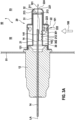
- the Figure 3 shows a cross section along the longitudinal axis LA of the exhaust gas sensor 1 according to a third exemplary embodiment.
- the exhaust gas sensor 1 has a sleeve-shaped sensor housing 12, in whose through hole a ceramic sensor element 14 is fixed.
- the ceramic sensor element 14 projects both on the side of the sensor housing 12 facing the exhaust gas (in Figure 3 right) as well as on the side of the sensor housing 12 facing away from the exhaust gas (in Figure 3 left) beyond the sensor housing 12.
- a sleeve-shaped, metallic protective tube 20 is welded to a circumferential collar 121 of the sensor housing 12 pointing in the exhaust gas direction.
- the protective tube 20 consists of an inner protective sleeve 21 and an outer protective sleeve 22.
- the inner protective sleeve 21 surrounds an exhaust-side end region 141 of the sensor element 14 with a radial and axial distance.
- the outer protective sleeve 22 surrounds the inner protective sleeve 21 in such a way that it rests on the inner protective tube 21 at the axial height of the collar 121 and is welded together with this to the collar 121 by means of a circumferential weld seam, and also on the exhaust side of the collar 121 between the outer protective sleeve 22 and inner protective sleeve 21 an annular space 30 is formed, that a contact area 31 is also formed on the exhaust side of the annular space 30, in which the inner protective sleeve 21 with its outer surface fully rests on the inner surface of the outer protective sleeve 22 and that furthermore on the exhaust side of the contact area 31 End space 32 is formed, which is delimited radially by the outer protective sleeve 22, is delimited on the side facing away from the exhaust gas by a bottom 211 of the inner protective sleeve 21 designed as a baffle plate and delimited on the side facing the exhaust gas by a bottom 221 of the outer protective slee
- the outer protective sleeve 22 has, for example, eight gas inlet openings 222, which are arranged at equal distances along the circumference of the outer protective sleeve 22 at the axial height of an end region 301 of the annular space 30 facing the exhaust gas.
- the gas inlet openings 222 each have a swirl element 223, which acts as a swirl flap is designed and gives the gas flowing into the annular space 30 an impulse directed towards the sensor housing 12 and an angular momentum directed in the direction of the longitudinal axis LA of the sensor, so that the exhaust gas rotates within the annular space 30 around the inner protective sleeve 21.
- swirl elements 223 can be dispensed with.
- the outer protective sleeve 22 also has a relatively large gas outlet opening 224 on the base 221.
- the gas outlet opening 224 can even be enlarged in such a way that the bottom 221 is completely or largely eliminated.
- the inner protective sleeve 21 points in the in Figure 3 Lower area has eight gas inlet openings 212, which run in two rows of four gas inlet openings 212 each running next to one another in the axial direction.
- the gas inlet openings 212 are arranged at the axial height of an approximately central region 302 of the annular space 30 in the axial direction.
- the gas inlet openings 212 are also arranged at the axial height of the sensor element 14. In one variant, only four gas inlet openings 212 are provided, which run in two rows next to each other in the axial direction, each with two gas inlet openings 212.
- the gas inlet openings 212 are arranged at the axial height of a sensitive area of the sensor element 14.
- the sensitive area of the sensor element 14 is, for example, an interdigital electrode structure 142 (see also Fig. 1b ), in this respect the exhaust gas sensor is a particle sensor for detecting soot in the exhaust gas of an internal combustion engine.
- the sensitive area could also be an electrode of an electrochemical cell and/or an opening leading into the interior of the sensor element, for example of a broadband lambda probe or a NOx sensor.
- a special feature of the exemplary embodiment is that all gas inlet openings 212 of the inner protective sleeve 21 are arranged only on a radial partial area and only on an axial partial area of the inner protective sleeve 21 and the sensitive area and all gas inlet openings 212 of the inner protective sleeve 21 are arranged on one another are opposite, so that exhaust gas entering the interior of the inner protective sleeve 21 always flows directly into the sensitive area.
- the inner protective sleeve 21 has a ring of eight off-center gas outlet openings 213 on its base 211.
- a further central gas outlet opening 213 is provided on the bottom 211 of the inner protective sleeve 21.
- this central gas outlet opening 213 can also be omitted.
- the gas outlet openings 213 of the inner protective sleeve 21 are circular, in particular with the exception of the gas outlet opening 213*, which is in the Figure 3a pointing downwards.
- the latter is designed as an oval hole or elongated hole and thus indicates the position of the gas inlet openings 212 of the inner protective sleeve 21 to the outside in such a way that it can be visually recognized when looking along the longitudinal axis LA of the sensor, see Figure 3b .
- the gas inlet openings 212 of the inner protective sleeve 21 are circular in the example and have a diameter of 1mm.
- the flow cross section of the gas inlet of the inner protective sleeve 21 is therefore 6mm 2 .
- the flow cross section of the gas outlet of the inner protective sleeve 21 is 10mm 2 in the example.
- the flow cross section of the gas outlet of the outer protective sleeve 22 is 14mm 2 in the example.
- the flow cross section of the gas inlet of the outer protective sleeve 22 is 10mm 2 in the example.
- the length of the sensor element 14 is approximately 55mm, the longitudinal extent of the protective tube 20 is approximately 28mm.
- the gas inlet of the inner protective sleeve 21 thus forms the smallest flow cross section when flowing through the protective tube 20, which results in the positive effects explained at the beginning.
- the diameter of the gas inlet openings 212 of the inner protective sleeve 21 can be reduced to 0.8mm or even to 0.6mm or even further.
- a top view of the sensor element 14 in the perspective from bottom to top in the Figure 3 is like in the Figure 1b shown.
- the sensor element 14 is planar and on the surface of the sensor element 14 there is an interdigital electrode structure 142 in an exhaust-side end region 141 arranged, which forms the sensitive area of the sensor element 14.
- the exhaust gas sensor 1 can be mounted in the wall 51 of an exhaust pipe 50 of an internal combustion engine in such a way that, as seen in a cross section of the exhaust pipe 50, the gas inlet of the outer protective sleeve 22 is arranged in an edge region 52 of the exhaust pipe, while the gas outlet of the outer protective sleeve 22 is in a central one Area 53 of the exhaust pipe is arranged, see Figure 3 .
- Exhaust gas flows through the exhaust pipe 50 essentially perpendicular to the longitudinal axis LA of the exhaust gas sensor 1, parallel to the plane of the drawing Figure 3 , in the direction of the double arrow 100.
- the Figure 4 shows a cross section along the longitudinal axis LA of the exhaust gas sensor 1 according to a fourth exemplary embodiment.
- the exhaust gas sensor 1 has a sleeve-shaped sensor housing 12, in whose through hole a ceramic sensor element 14 is fixed.
- the ceramic sensor element 14 projects both on the side of the sensor housing 12 facing the exhaust gas (in Figure 4 right) as well as on the side of the sensor housing 12 facing away from the exhaust gas (in Figure 4 left) beyond the sensor housing 12.
- the protective tube 20 consists of an inner protective sleeve 21 and an outer protective sleeve 22.
- the inner protective sleeve 21 surrounds an exhaust-side end region 141 of the sensor element 14 with a radial and axial distance.
- the outer protective sleeve 22 surrounds the inner protective sleeve 21 in such a way that it rests on the inner protective tube 21 at the axial height of the collar 121 and is welded together with this to the collar 121 by means of a circumferential weld and that furthermore on the exhaust side of the collar 121 between the outer protective sleeve 22 and inner protective sleeve 21 an annular space 30 is formed.
- the outer protective sleeve 22 On the exhaust side of the annular space 30, the outer protective sleeve 22 has a relatively large central gas outlet opening 224, in which the inner protective sleeve 21 is fixed and through which the inner protective sleeve 21 protrudes on the exhaust side over the outer protective sleeve 22 in a projection area 33.
- the inner protective sleeve 21 is fixed, in particular pressed, in the gas outlet opening 224 of the outer protective sleeve 22 without any gaps, i.e. tightly.
- the projection area 33 ends on the exhaust side with a base 211 of the inner protective sleeve 21.
- the outer protective sleeve 22 has, for example, eight gas inlet openings 222, which are arranged at equal distances along the circumference of the outer protective sleeve 22 at the axial height of an end region 301 of the annular space 30 facing the exhaust gas.
- the gas inlet openings 222 each have a swirl element 223, which is designed as a swirl flap and gives the gas flowing into the annular space 30 an impulse directed towards the sensor housing 12 and an angular momentum directed in the direction of the longitudinal axis LA of the sensor, so that the exhaust gas within the annular space 30 rotates around the inner protective sleeve 21.
- swirl elements 223 can be dispensed with.
- the inner protective sleeve 21 points in the in Figure 4 Lower area has eight gas inlet openings 212, which run in two rows of four gas inlet openings 212 each running next to one another in the axial direction.
- the gas inlet openings 212 are arranged at the axial height of an approximately central region 302 of the annular space 30 in the axial direction.
- the Gas inlet openings 212 are also arranged at the axial height of the sensor element 14. In one variant, only four gas inlet openings 212 are provided, which run in two rows next to each other in the axial direction, each with two gas inlet openings 212.
- the gas inlet openings 212 are arranged at the axial height of a sensitive area of the sensor element 14.
- the sensitive area of the sensor element 14 is, for example, an interdigital electrode structure 142 (see also Fig. 1b ), in this respect the exhaust gas sensor is a particle sensor for detecting soot in the exhaust gas of an internal combustion engine.
- the sensitive area could also be an electrode of an electrochemical cell and/or an opening leading into the interior of the sensor element, for example of a broadband lambda probe or a NOx sensor.
- a special feature of the exemplary embodiment is that all gas inlet openings 212 of the inner protective sleeve 21 are arranged only on a radial partial area and only on an axial partial area of the inner protective sleeve 21 and the sensitive area and all gas inlet openings 212 of the inner protective sleeve 21 are opposite one another, so that in The exhaust gas entering the interior of the inner protective sleeve 21 always flows directly into the sensitive area.
- the inner protective sleeve 21 has a central, relatively large gas outlet opening 213 on its base 211.
- the gas inlet openings 212 of the inner protective sleeve 21 are circular in the example and have a diameter of 1mm.
- the flow cross section of the gas inlet of the inner protective sleeve 21 is therefore 6mm 2 .
- the flow cross section of the gas outlet of the inner protective sleeve 21 is 14mm 2 in the example.
- the flow cross section of the gas inlet of the outer protective sleeve 22 is 10mm 2 in the example.
- the length of the sensor element 14 is approximately 55mm, the longitudinal extent of the protective tube 20 is approximately 28mm.
- the gas inlet of the inner protective sleeve 21 thus forms the smallest flow cross section when flowing through the protective tube 20, which results in the positive effects explained at the beginning.
- the diameter of the gas inlet openings 212 of the inner protective sleeve 21 can be reduced to 0.8mm or even to 0.6mm or even further.
- a top view of the sensor element 14 in the perspective from bottom to top in the Figure 4 is as in Figure 1b shown.
- the sensor element 14 is designed to be planar and an interdigital electrode structure 142 is arranged on the surface of the sensor element 14 in an exhaust-side end region 141, which forms the sensitive region of the sensor element 14.
- the exhaust gas sensor 1 can be mounted in the wall 51 of an exhaust pipe 50 of an internal combustion engine in such a way that, seen in a cross section of the exhaust pipe 50, the gas inlet of the outer protective sleeve 22 is arranged in an edge region 52 of the exhaust pipe, while the gas outlet of the inner protective sleeve 21 is in a central one Area 53 of the exhaust pipe is arranged, see Figure 4 .
- Exhaust gas flows through the exhaust pipe 50 essentially perpendicular to the longitudinal axis LA of the exhaust gas sensor 1, parallel to the plane of the drawing Figure 4 , in the direction of the double arrow 100.
- the Figure 5 shows a cross section along the longitudinal axis LA of the exhaust gas sensor 1 according to a fifth exemplary embodiment.
- the exhaust gas sensor 1 has a sleeve-shaped sensor housing 12, in the through hole of which ceramic sensor element 14 is fixed.
- the ceramic sensor element 14 projects both on the side of the sensor housing 12 facing the exhaust gas (in Figure 5 right) as well as on the side of the sensor housing 12 facing away from the exhaust gas (in Figure 5 left) beyond the sensor housing 12.
- a sleeve-shaped, metallic protective tube 20 is welded to a circumferential collar 121 of the sensor housing 12 pointing in the exhaust gas direction.
- the protective tube 20 consists of an inner protective sleeve 21 and an outer protective sleeve 22.
- the inner protective sleeve 21 surrounds an exhaust-side end region 141 of the sensor element 14 with a radial and axial distance.
- the outer protective sleeve 22 surrounds the inner protective sleeve 21 in such a way that it rests on the inner protective tube 21 at the axial height of the collar 121 and is welded together with this to the collar 121 by means of a circumferential weld seam, and also on the exhaust side of the collar 121 between the outer protective sleeve 22 and inner protective sleeve 21 an annular space 30 is formed, that a contact area 31 is also formed on the exhaust side of the annular space 30, in which the inner protective sleeve 21 with its outer surface fully rests on the inner surface of the outer protective sleeve 22 and that furthermore on the exhaust side of the contact area 31 End space 32 is formed, which is delimited radially by a region of the outer protective sleeve 22 which is slightly radially tapered by means of an annular shoulder 226, is open towards the interior of the inner protective sleeve 21 on the side facing away from the exhaust gas and by a base 221 on the side facing the exhaust gas
- the outer protective sleeve 22 has, for example, eight gas inlet openings 222, which are arranged at equal distances along the circumference of the outer protective sleeve 22 at the axial height of an end region 301 of the annular space 30 facing the exhaust gas.
- the gas inlet openings 222 each have a swirl element 223, which is designed as a swirl flap and gives the gas flowing into the annular space 30 an impulse directed towards the sensor housing 12 and an angular momentum directed in the direction of the longitudinal axis LA of the sensor, so that the exhaust gas within the annular space 30 rotates around the inner protective sleeve 21.
- swirl elements 223 can be dispensed with.
- the outer protective sleeve 22 also has a relatively large gas outlet opening 224 on the base 221.
- the gas outlet opening 224 can even be enlarged in such a way that the bottom 221 is completely or largely eliminated.
- the inner protective sleeve 21 has, for example, eight gas inlet openings 212, which are arranged at equal distances along the circumference of the inner protective sleeve 21 on the housing side at the axial height of a region 303 of the annular space 30 on the housing side in the axial direction.
- the gas inlet openings 212 are also arranged at the axial height of the sensor element 14.
- the gas inlet openings 212 are arranged on the housing side of a sensitive area of the sensor element 14.
- the sensitive area of the sensor element 14 is an interdigital electrode structure 142 (see also Fig. 1b ), in this respect the exhaust gas sensor is a particle sensor for detecting soot in the exhaust gas of an internal combustion engine.
- the gas inlet openings 212 are in particular rectangular and in particular each have a particularly rectangular deflection element 215, which is in particular in the form of a strip pressed into the sensor housing 12 and which is an exhaust gas entering the annular space 30 deflects in the direction of the gas outlet of the inner protective sleeve 21.
- the gas inlet opening 212 can also be assigned a deflection element 215, which has a different shape, in particular the shape of the swirl flap, and which deflects an exhaust gas entering the annular space 30 in the direction of the gas outlet of the inner protective sleeve 21.
- the gas inlet openings 212 of the inner protective sleeve 21 are in this Example arranged on the axial side of the sensitive area of the sensor element 14 facing away from the exhaust gas.
- the exhaust gas flowing into the interior of the inner protective sleeve 21 is directed by the deflection elements 215 onto the sensitive area of the sensor element 14.
- the inner protective sleeve 21 can have a ring of eight off-center gas outlet openings 213 on its base 211.
- a further central gas outlet opening 213 can be provided on the bottom 211 of the inner protective sleeve.
- the gas inlet openings 212 of the inner protective sleeve 21 are rectangular in the example and have a total flow cross section of 8mm 2 .
- the flow cross section of the gas outlet of the inner protective sleeve 21 is over 50mm 2 in the example.
- the flow cross section of the gas outlet of the outer protective sleeve 22 is 14mm 2 in the example.
- the flow cross section of the gas inlet of the outer protective sleeve 22 is 10mm 2 in the example.
- the length of the sensor element 14 is approximately 55mm, the longitudinal extent of the protective tube 20 is approximately 28mm.
- the gas inlet of the inner protective sleeve 21 thus forms the smallest flow cross section when flowing through the protective tube 20, which results in the positive effects explained at the beginning.
- the cross section of the gas inlet openings 212 of the inner protective sleeve 21 can be reduced to 0.8 or even 0.6mm 2 each.
- a top view of the sensor element 14 in the perspective from bottom to top in the Figure 5 is as in Figure 1b shown.
- the sensor element 14 is designed to be planar and an interdigital electrode structure 142 is arranged on the surface of the sensor element 14 in an exhaust-side end region 141, which forms the sensitive region of the sensor element 14.
- a cylindrical sensor element 14 can also be used.
- the exhaust gas sensor 1 can be mounted in the wall 51 of an exhaust pipe 50 of an internal combustion engine in such a way that, as seen in a cross section of the exhaust pipe 50, the gas inlet of the outer protective sleeve 22 is arranged in an edge region 52 of the exhaust pipe, while the gas outlet of the outer protective sleeve 22 is in a central one Area 53 of the exhaust pipe is arranged, see Figure 5 .
- Exhaust gas flows through the exhaust pipe 50 essentially perpendicular to the longitudinal axis LA of the exhaust gas sensor 1, parallel to the plane of the drawing Figure 5 , in the direction of the double arrow 100.
- the Figure 6 shows a cross section along the longitudinal axis LA of the exhaust gas sensor 1 according to a sixth exemplary embodiment.
- the exhaust gas sensor 1 has a sleeve-shaped sensor housing 12, in whose through hole a ceramic sensor element 14 is fixed.
- the ceramic sensor element 14 projects both on the side of the sensor housing 12 facing the exhaust gas (in Figure 6 right) as well as on the side of the sensor housing 12 facing away from the exhaust gas (in Figure 6 left) beyond the sensor housing 12.
- a sleeve-shaped, metallic protective tube 20 is welded to a circumferential collar 121 of the sensor housing 12 pointing in the exhaust gas direction.
- the protective tube 20 consists of an inner protective sleeve 21 and an outer protective sleeve 22.
- the inner protective sleeve 21 surrounds an exhaust-side end region 141 of the sensor element 14 with a radial and axial distance.
- the outer protective sleeve 22 surrounds the inner protective sleeve 21 in such a way that it rests on the inner protective tube 21 at the axial height of the collar 121 and is welded together with this to the collar 121 by means of a circumferential weld and that furthermore on the exhaust side of the collar 121 between the outer protective sleeve 22 and inner protective sleeve 21 an annular space 30 is formed.
- the outer protective sleeve 22 On the exhaust side of the annular space 30, the outer protective sleeve 22 has a relatively large central gas outlet opening 224, in which the inner protective sleeve 21 is fixed and through which the inner protective sleeve 21 protrudes on the exhaust side over the outer protective sleeve 22 in a projection area 33.
- the inner protective sleeve 21 is fixed, in particular pressed, in the gas outlet opening 224 of the outer protective sleeve 22 without any gaps, i.e. tightly.
- the projection area 33 ends on the exhaust side with a base 211 of the inner protective sleeve 21.
- the outer protective sleeve 22 has, for example, eight gas inlet openings 222, which are arranged at equal distances along the circumference of the outer protective sleeve 22 at the axial height of an end region 301 of the annular space 30 facing the exhaust gas.
- the gas inlet openings 222 each have a swirl element 223, which is designed as a swirl flap and gives the gas flowing into the annular space 30 an impulse directed towards the sensor housing 12 and an angular momentum directed in the direction of the longitudinal axis LA of the sensor, so that the exhaust gas within the annular space 30 rotates around the inner protective sleeve 21.
- swirl elements 223 can be dispensed with.
- the inner protective sleeve 21 has, for example, eight gas inlet openings 212, which are arranged at equal distances along the circumference of the inner protective sleeve 21 in a region 303 of the annular space 30 on the housing side in the axial direction.
- the gas inlet openings 212 are also arranged at the axial height of the sensor element 14.
- the gas inlet openings 212 are arranged on the housing side of a sensitive area of the sensor element 14.
- the sensitive area of the sensor element 14 is an interdigital electrode structure 142 (see also Fig. 1b ), in this respect the exhaust gas sensor is a particle sensor for detecting soot in the exhaust gas of an internal combustion engine.
- the gas inlet openings 212 are in particular rectangular and in particular each have a particularly rectangular deflection element 215, which is in particular in the form of a strip pressed into the sensor housing 12 and which is an exhaust gas entering the annular space 30 deflects in the direction of the gas outlet of the inner protective sleeve 21.
- the gas inlet opening 212 can also be assigned a deflection element 215, which has a different shape, in particular the shape of the swirl flap, and which deflects an exhaust gas entering the annular space 30 in the direction of the gas outlet of the inner protective sleeve 21.
- the gas inlet openings 212 of the inner protective sleeve 21 are arranged on the axial side of the sensitive area of the sensor element 14 facing away from the exhaust gas.
- the exhaust gas flowing into the interior of the inner protective sleeve 21 is directed by the deflection elements 215 onto the sensitive area of the sensor element 14.
- the inner protective sleeve 21 has a central, relatively large gas outlet opening 213 on its base 211.
- the gas inlet openings 212 of the inner protective sleeve 21 are rectangular in the example and have a total flow cross section of 8mm 2 .
- the flow cross section of the gas outlet of the inner protective sleeve 21 is over 14mm 2 in the example.
- the flow cross section of the gas inlet of the outer protective sleeve 22 is 10mm 2 in the example.
- the length of the sensor element 14 is approximately 55mm, the longitudinal extent of the protective tube 20 is approximately 28mm.
- the gas inlet of the inner protective sleeve 21 thus forms the smallest flow cross section when flowing through the protective tube 20, which results in the positive effects explained at the beginning.
- the cross section of the gas inlet openings 212 of the inner protective sleeve 21 can be reduced to 0.8 or even 0.6mm 2 each.
- a top view of the sensor element 14 in the perspective from bottom to top in the Figure 6 is as in Figure 1b shown.
- the sensor element 14 is designed to be planar and an interdigital electrode structure 142 is arranged on the surface of the sensor element 14 in an exhaust-side end region 141, which forms the sensitive region of the sensor element 14.
- the exhaust gas sensor 1 can be mounted in the wall 51 of an exhaust pipe 50 of an internal combustion engine in such a way that, seen in a cross section of the exhaust pipe 50, the gas inlet of the outer protective sleeve 22 is arranged in an edge region 52 of the exhaust pipe, while the gas outlet of the inner protective sleeve 21 is in a central one Area 53 of the exhaust pipe is arranged, see Figure 6 .
- Exhaust gas flows through the exhaust pipe 50 essentially perpendicular to the longitudinal axis LA of the exhaust gas sensor 1, parallel to the plane of the drawing Figure 6 , in the direction of the double arrow 100.
Landscapes
- Chemical & Material Sciences (AREA)
- Health & Medical Sciences (AREA)
- Life Sciences & Earth Sciences (AREA)
- General Physics & Mathematics (AREA)
- Pathology (AREA)
- Analytical Chemistry (AREA)
- Biochemistry (AREA)
- General Health & Medical Sciences (AREA)
- Physics & Mathematics (AREA)
- Immunology (AREA)
- Dispersion Chemistry (AREA)
- Chemical Kinetics & Catalysis (AREA)
- Electrochemistry (AREA)
- Engineering & Computer Science (AREA)
- Molecular Biology (AREA)
- Combustion & Propulsion (AREA)
- Mechanical Engineering (AREA)
- General Engineering & Computer Science (AREA)
- Measuring Oxygen Concentration In Cells (AREA)
Claims (10)
- Capteur de gaz d'échappement, comprenant un boîtier de capteur (12) en forme de manchon, un élément capteur (14) fixé dans le boîtier de capteur (12) et faisant saillie au-delà du boîtier de capteur (12) côté gaz d'échappement, et un tube de protection (20) en forme de manchon qui est fixé au boîtier de capteur (12) côté gaz d'échappement, dans lequel le tube de protection (20) est composé d'un manchon de protection interne (21) et d'un manchon de protection externe (22), dans lequel le manchon de protection interne (21) entoure une zone d'extrémité (141) côté gaz d'échappement de l'élément capteur (14), dans lequel le manchon de protection externe (22) entoure le manchon de protection interne (21) au moins par endroits de façon à réaliser un espace annulaire (30) entre le manchon de protection externe (22) et le manchon de protection interne (21), dans lequel le manchon de protection externe (22) et le manchon de protection interne (21) présentent respectivement une sortie de gaz et une entrée de gaz, et un passage par le tube de protection (20), dans le cas d'un gradient négatif, orienté dans la direction axiale, de la pression statique dans les gaz d'échappement, donc si la pression statique à l'extrémité axiale côté gaz d'échappement du tube de protection (20) est inférieure à celle à l'extrémité axiale, détournée des gaz d'échappement, du tube de protection (20), le tube de protection (20) a lieu forcément depuis l'entrée de gaz du manchon de protection externe (22) dans l'espace annulaire (30), de là à travers l'entrée de gaz du manchon de protection interne (21) vers l'intérieur du manchon de protection interne (21), et de là à travers les sorties de gaz du manchon extérieur et du manchon intérieur (21, 22), dans lequel l'entrée de gaz du manchon de protection interne (21) forme la plus petite section transversale d'écoulement lors du passage par le tube de protection (20), et dans lequel le capteur de gaz d'échappement est un capteur de particules pour déterminer la concentration en suie dans les gaz d'échappement d'un moteur à combustion interne, et l'entrée de gaz du manchon de protection interne (21) est disposée à la hauteur axiale de l'élément capteur (14), dans lequel une zone sensible est disposée sur l'élément capteur (14), dans lequel l'élément capteur (14) est réalisé sous forme d'élément capteur plan (14), et la zone sensible n'est disposée que sur une partie d'une surface latérale de l'élément capteur (14), et l'entrée de gaz du manchon de protection interne (21) n'est disposée que sur une zone partielle radiale et/ou axiale du manchon de protection interne (21), et la zone sensible et l'entrée de gaz du manchon de protection interne (21) sont opposées l'une à l'autre de sorte que des gaz d'échappement entrant à l'intérieur du manchon de protection interne (21) atteignent toujours directement la zone sensible, et la zone sensible de l'élément capteur (14) est une structure d'électrodes interdigitées (142).
- Capteur de gaz d'échappement selon la revendication 1, caractérisé en ce que la sortie de gaz du manchon de protection externe (22) présente au moins une ouverture de sortie de gaz (224) dans laquelle est fixé le manchon de protection interne (21) et à travers laquelle le manchon de protection interne (21) dépasse du manchon de protection externe (22) côté gaz d'échappement, et la sortie de gaz du manchon de protection interne (21) relie directement l'intérieur du manchon de protection interne (21) à une zone à l'extérieur du capteur de gaz d'échappement (1).
- Capteur de gaz d'échappement selon la revendication 1, caractérisé en ce que le manchon de protection externe (22) dépasse axialement dans la direction côté gaz d'échappement du manchon de protection interne (21), et un espace frontal (32), séparé de l'espace annulaire (30), est réalisé entre le manchon de protection externe (22) et le manchon de protection interne (21), et la sortie de gaz du manchon de protection interne relie l'intérieur du manchon de protection interne (21) à l'espace frontal (32) et la sortie de gaz du manchon de protection externe relie l'espace frontal (32) à une zone à l'extérieur du capteur de gaz d'échappement (1).
- Capteur de gaz d'échappement selon l'une quelconque des revendications 1 à 3, caractérisé en ce que l'entrée de gaz du manchon de protection externe (22) présente au moins une ouverture d'entrée de gaz (222) qui est munie d'au moins un élément de turbulence (223) qui dévie des gaz d'échappement entrant dans l'espace annulaire (30) de telle sorte qu'à l'intérieur de l'espace annulaire (30), ils tournent autour du manchon de protection interne (21).
- Capteur de gaz d'échappement selon l'une quelconque des revendications 1 ou 4, caractérisé en ce que l'entrée de gaz du manchon de protection interne (21) présente au moins une ouverture d'entrée de gaz (212) qui présente au moins un élément déflecteur (215) qui dévie des gaz d'échappement entrant dans l'espace annulaire (30) en direction de la sortie de gaz du manchon de protection interne (21).
- Capteur de gaz d'échappement selon l'une quelconque des revendications 1 à 5, caractérisé en ce que l'entrée de gaz du manchon de protection interne (21) est composée d'une pluralité d'ouvertures d'entrée de gaz (212), en particulier d'au moins 8 ou d'au moins 10 ouvertures d'entrée de gaz (212), dont chaque ouverture d'entrée de gaz (212) individuelle présente une section transversale d'écoulement dont la racine carrée est inférieure à 1/18 de la dimension longitudinale du tube de protection (20) et/ou est inférieure à 1/35 de la dimension longitudinale de l'élément capteur (14), par exemple avec une section transversale d'écoulement ne dépassant pas 1 mm2.
- Capteur de gaz d'échappement selon l'une quelconque des revendications 1 à 6, caractérisé en ce que l'entrée de gaz du manchon de protection interne (21) est composée d'une pluralité d'ouvertures d'entrée de gaz (212) qui sont disposées les unes au-dessus des autres dans la direction longitudinale, en particulier sur une seule rangée ou sur deux rangées disposées l'une à côté de l'autre.
- Capteur de gaz d'échappement selon l'une quelconque des revendications 1 à 7, caractérisé en ce que l'entrée de gaz du manchon de protection interne (21) est composée d'une pluralité d'ouvertures d'entrée de gaz (212) qui sont disposées les unes à côté des autres dans la direction circonférentielle, en particulier sur une seule rangée ou sur deux ou plusieurs rangées disposées les unes au-dessus des autres.
- Capteur de gaz d'échappement selon l'une quelconque des revendications 1 à 8, caractérisé en ce que l'entrée de gaz du manchon de protection interne (21) présente une section transversale d'écoulement qui est de 10 % à 95 %, en particulier de 25 % à 50 % ou de 50 % à 80 %, de la section transversale d'écoulement de la sortie de gaz du manchon de protection interne (21), et/ou est de 10 % à 95 %, en particulier de 25 % à 50 % ou de 50 % à 80 % de la section transversale d'écoulement de la sortie de gaz du manchon de protection externe (22).
- Utilisation d'un capteur de gaz d'échappement (1) selon l'une quelconque des revendications 1 à 9 dans une conduite de gaz d'échappement (50) d'un moteur à combustion interne, caractérisée en ce qu'une section transversale de la conduite de gaz d'échappement (50) présente une zone plutôt centrale (53) et une zone plutôt périphérique (52) qui entoure la zone plutôt centrale (53), et dans laquelle une vitesse d'écoulement des gaz d'échappement dans la conduite de gaz d'échappement (50) dans la zone plutôt centrale (53) est en principe supérieure à celle dans la zone plutôt périphérique (52), et dans laquelle l'entrée de gaz du manchon de protection externe (22) est disposée dans la zone plutôt périphérique (52) et la sortie de gaz du manchon de protection interne ou externe (21, 22) est disposée dans la zone plutôt centrale (53).
Applications Claiming Priority (2)
| Application Number | Priority Date | Filing Date | Title |
|---|---|---|---|
| DE102017206308.4A DE102017206308A1 (de) | 2017-04-12 | 2017-04-12 | Abgassensor, insbesondere Partikelsensor |
| PCT/EP2018/058527 WO2018188997A1 (fr) | 2017-04-12 | 2018-04-04 | Capteur de gaz d'échappement, en particulier capteur de particules |
Publications (2)
| Publication Number | Publication Date |
|---|---|
| EP3610251A1 EP3610251A1 (fr) | 2020-02-19 |
| EP3610251B1 true EP3610251B1 (fr) | 2024-03-20 |
Family
ID=61972098
Family Applications (1)
| Application Number | Title | Priority Date | Filing Date |
|---|---|---|---|
| EP18717544.3A Active EP3610251B1 (fr) | 2017-04-12 | 2018-04-04 | Capteur de particules |
Country Status (5)
| Country | Link |
|---|---|
| EP (1) | EP3610251B1 (fr) |
| KR (1) | KR102498947B1 (fr) |
| CN (1) | CN110494742A (fr) |
| DE (1) | DE102017206308A1 (fr) |
| WO (1) | WO2018188997A1 (fr) |
Families Citing this family (6)
| Publication number | Priority date | Publication date | Assignee | Title |
|---|---|---|---|---|
| JP7239434B2 (ja) * | 2019-10-03 | 2023-03-14 | 日本碍子株式会社 | ガスセンサ及び保護カバー |
| CN110905640B (zh) * | 2019-12-03 | 2021-05-11 | 安徽江淮汽车集团股份有限公司 | 传感器组件及套筒 |
| CN113776843A (zh) * | 2021-10-15 | 2021-12-10 | 重庆康明斯发动机有限公司 | 一种接头装置及检测软管 |
| DE102022210609A1 (de) * | 2022-10-07 | 2024-04-18 | Robert Bosch Gesellschaft mit beschränkter Haftung | Partikelsensor |
| CN116380740B (zh) * | 2023-05-16 | 2023-08-08 | 江苏省环境监测中心 | 一种废气浓度检测机构及其使用方法 |
| CN119125223B (zh) * | 2024-10-30 | 2025-08-29 | 北京东分科技发展有限公司 | 一种哈奇式热导原理气体浓度传感器 |
Family Cites Families (19)
| Publication number | Priority date | Publication date | Assignee | Title |
|---|---|---|---|---|
| DE4034072A1 (de) | 1990-10-26 | 1992-04-30 | Bosch Gmbh Robert | Gasmessfuehler, insbesondere zur bestimmung des sauerstoffgehaltes in abgasen von brennkraftmaschinen |
| DE19705402B4 (de) * | 1996-07-17 | 2007-04-26 | Robert Bosch Gmbh | Gassensor |
| DE19739435A1 (de) * | 1997-09-09 | 1999-03-11 | Bosch Gmbh Robert | Meßfühler |
| EP0978721B1 (fr) * | 1998-08-05 | 2011-04-06 | Ngk Spark Plug Co., Ltd | Capteur de gaz |
| JP4552342B2 (ja) * | 2000-06-30 | 2010-09-29 | 株式会社デンソー | ガスセンサの製造方法 |
| DE102004033958A1 (de) * | 2004-07-14 | 2006-02-09 | Robert Bosch Gmbh | Messfühler |
| JP4680662B2 (ja) * | 2005-04-26 | 2011-05-11 | 日本特殊陶業株式会社 | ガスセンサ |
| JP2006337341A (ja) * | 2005-06-06 | 2006-12-14 | Hitachi Ltd | 酸素センサ |
| US20080016946A1 (en) * | 2006-07-18 | 2008-01-24 | Honeywell International Inc. | Gas sensor packaging for elevated temperature and harsh environment and related methods |
| DE102006035058A1 (de) * | 2006-07-28 | 2008-01-31 | Robert Bosch Gmbh | Gassensor |
| JP5475715B2 (ja) * | 2011-04-27 | 2014-04-16 | 日本特殊陶業株式会社 | センサ |
| KR101318526B1 (ko) * | 2013-02-25 | 2013-10-16 | 주식회사 현대케피코 | 자동차용 산소센서의 보호튜브 |
| WO2014157279A1 (fr) * | 2013-03-28 | 2014-10-02 | 日本碍子株式会社 | Capteur de gaz |
| JP6059110B2 (ja) * | 2013-08-09 | 2017-01-11 | 日本特殊陶業株式会社 | センサ素子およびセンサ |
| KR101382056B1 (ko) * | 2013-09-26 | 2014-04-04 | 주식회사 현대케피코 | 자동차용 산소센서의 보호튜브 |
| DE102013221255A1 (de) * | 2013-10-21 | 2015-04-23 | Robert Bosch Gmbh | Sensorvorrichtung zur Erfassung mindestens einer Eigenschaft eines fluiden Mediums |
| JP6233207B2 (ja) * | 2014-06-30 | 2017-11-22 | 株式会社デンソー | ガスセンサ |
| JP6626435B2 (ja) * | 2014-08-22 | 2019-12-25 | 日本特殊陶業株式会社 | 微粒子センサ |
| RU2707983C2 (ru) * | 2015-02-17 | 2019-12-03 | Форд Глобал Текнолоджиз, Ллк | Система (варианты) и способ измерения параметров твердых частиц |
-
2017
- 2017-04-12 DE DE102017206308.4A patent/DE102017206308A1/de not_active Withdrawn
-
2018
- 2018-04-04 EP EP18717544.3A patent/EP3610251B1/fr active Active
- 2018-04-04 KR KR1020197029875A patent/KR102498947B1/ko active Active
- 2018-04-04 WO PCT/EP2018/058527 patent/WO2018188997A1/fr not_active Ceased
- 2018-04-04 CN CN201880024488.8A patent/CN110494742A/zh active Pending
Also Published As
| Publication number | Publication date |
|---|---|
| KR20190139219A (ko) | 2019-12-17 |
| EP3610251A1 (fr) | 2020-02-19 |
| DE102017206308A1 (de) | 2018-10-18 |
| WO2018188997A1 (fr) | 2018-10-18 |
| CN110494742A (zh) | 2019-11-22 |
| KR102498947B1 (ko) | 2023-02-15 |
Similar Documents
| Publication | Publication Date | Title |
|---|---|---|
| EP3610251A1 (fr) | Capteur de gaz d'échappement, en particulier capteur de particules | |
| DE102007035035B4 (de) | Gassensor | |
| EP3377884B1 (fr) | Capteur de gaz d'échappement | |
| EP3298254B1 (fr) | Système d'échappement avec capteur de gaz, en particulier avec un capteur de matières particulaires | |
| WO1997033165A1 (fr) | Detecteur de gaz | |
| DE102017005577A1 (de) | Gassensor | |
| DE102017005575A1 (de) | Gassensor | |
| DE102014207227A1 (de) | Gas Sensor | |
| DE112013005889B4 (de) | Zündkerze für Verbrennungsmotor | |
| DE4009890A1 (de) | Messfuehler fuer die bestimmung des sauerstoffgehaltes in gasen | |
| DE102012017178A1 (de) | Abgasreinigungsvorrichtung | |
| DE102020005913A1 (de) | Gassensor und schutzabdeckung | |
| DE69736313T2 (de) | Einrichtung zur Gaskonzentrationsdetektion | |
| DE102017215689B4 (de) | Partikelsensor für eine Brennkraftmaschine | |
| EP2005138B1 (fr) | Capteur pour la détection de particules dans un fluide et procédé de détection de particules dans un fluide | |
| DE102018203389A1 (de) | Gassensor | |
| DE102017123433A1 (de) | Verfahren und system zum erfassen von feinstaub in abgas | |
| DE19523978C2 (de) | Abgassensor mit geringer Ansprechzeit | |
| DE102017109389A1 (de) | Verfahren und system zur erfassung von feinstaub in abgas | |
| DE102017215798A1 (de) | Partikelsensor mit Umlenkelement | |
| AT520416B1 (de) | Messvorrichtung zum Detektieren einer Messgröße eines partikelbeladenen Fluids | |
| EP3327261B1 (fr) | Dispositif de traitement de gaz d'échappement | |
| DE112015002797B4 (de) | Gassensor zum Erfassen einer Gaskonzentration | |
| DE102023212562A1 (de) | Abgassensor, insbesondere Partikelsensor | |
| DE9014826U1 (de) | Gasmeßfühler, insbesondere zur Bestimmung des Sauerstoffgehaltes in Abgasen von Brennkraftmaschinen |
Legal Events
| Date | Code | Title | Description |
|---|---|---|---|
| STAA | Information on the status of an ep patent application or granted ep patent |
Free format text: STATUS: UNKNOWN |
|
| STAA | Information on the status of an ep patent application or granted ep patent |
Free format text: STATUS: THE INTERNATIONAL PUBLICATION HAS BEEN MADE |
|
| PUAI | Public reference made under article 153(3) epc to a published international application that has entered the european phase |
Free format text: ORIGINAL CODE: 0009012 |
|
| STAA | Information on the status of an ep patent application or granted ep patent |
Free format text: STATUS: REQUEST FOR EXAMINATION WAS MADE |
|
| 17P | Request for examination filed |
Effective date: 20191112 |
|
| AK | Designated contracting states |
Kind code of ref document: A1 Designated state(s): AL AT BE BG CH CY CZ DE DK EE ES FI FR GB GR HR HU IE IS IT LI LT LU LV MC MK MT NL NO PL PT RO RS SE SI SK SM TR |
|
| AX | Request for extension of the european patent |
Extension state: BA ME |
|
| RAP1 | Party data changed (applicant data changed or rights of an application transferred) |
Owner name: ROBERT BOSCH GMBH |
|
| DAV | Request for validation of the european patent (deleted) | ||
| DAX | Request for extension of the european patent (deleted) | ||
| STAA | Information on the status of an ep patent application or granted ep patent |
Free format text: STATUS: EXAMINATION IS IN PROGRESS |
|
| 17Q | First examination report despatched |
Effective date: 20220211 |
|
| GRAP | Despatch of communication of intention to grant a patent |
Free format text: ORIGINAL CODE: EPIDOSNIGR1 |
|
| STAA | Information on the status of an ep patent application or granted ep patent |
Free format text: STATUS: GRANT OF PATENT IS INTENDED |
|
| INTG | Intention to grant announced |
Effective date: 20240103 |
|
| GRAS | Grant fee paid |
Free format text: ORIGINAL CODE: EPIDOSNIGR3 |
|
| GRAA | (expected) grant |
Free format text: ORIGINAL CODE: 0009210 |
|
| STAA | Information on the status of an ep patent application or granted ep patent |
Free format text: STATUS: THE PATENT HAS BEEN GRANTED |
|
| AK | Designated contracting states |
Kind code of ref document: B1 Designated state(s): AL AT BE BG CH CY CZ DE DK EE ES FI FR GB GR HR HU IE IS IT LI LT LU LV MC MK MT NL NO PL PT RO RS SE SI SK SM TR |
|
| REG | Reference to a national code |
Ref country code: GB Ref legal event code: FG4D Free format text: NOT ENGLISH |
|
| REG | Reference to a national code |
Ref country code: CH Ref legal event code: EP |
|
| REG | Reference to a national code |
Ref country code: DE Ref legal event code: R096 Ref document number: 502018014280 Country of ref document: DE |
|
| REG | Reference to a national code |
Ref country code: IE Ref legal event code: FG4D Free format text: LANGUAGE OF EP DOCUMENT: GERMAN |
|
| PG25 | Lapsed in a contracting state [announced via postgrant information from national office to epo] |
Ref country code: LT Free format text: LAPSE BECAUSE OF FAILURE TO SUBMIT A TRANSLATION OF THE DESCRIPTION OR TO PAY THE FEE WITHIN THE PRESCRIBED TIME-LIMIT Effective date: 20240320 |
|
| REG | Reference to a national code |
Ref country code: LT Ref legal event code: MG9D |
|
| PG25 | Lapsed in a contracting state [announced via postgrant information from national office to epo] |
Ref country code: GR Free format text: LAPSE BECAUSE OF FAILURE TO SUBMIT A TRANSLATION OF THE DESCRIPTION OR TO PAY THE FEE WITHIN THE PRESCRIBED TIME-LIMIT Effective date: 20240621 |
|
| PG25 | Lapsed in a contracting state [announced via postgrant information from national office to epo] |
Ref country code: RS Free format text: LAPSE BECAUSE OF FAILURE TO SUBMIT A TRANSLATION OF THE DESCRIPTION OR TO PAY THE FEE WITHIN THE PRESCRIBED TIME-LIMIT Effective date: 20240620 Ref country code: HR Free format text: LAPSE BECAUSE OF FAILURE TO SUBMIT A TRANSLATION OF THE DESCRIPTION OR TO PAY THE FEE WITHIN THE PRESCRIBED TIME-LIMIT Effective date: 20240320 |
|
| REG | Reference to a national code |
Ref country code: NL Ref legal event code: MP Effective date: 20240320 |
|
| PG25 | Lapsed in a contracting state [announced via postgrant information from national office to epo] |
Ref country code: RS Free format text: LAPSE BECAUSE OF FAILURE TO SUBMIT A TRANSLATION OF THE DESCRIPTION OR TO PAY THE FEE WITHIN THE PRESCRIBED TIME-LIMIT Effective date: 20240620 Ref country code: NO Free format text: LAPSE BECAUSE OF FAILURE TO SUBMIT A TRANSLATION OF THE DESCRIPTION OR TO PAY THE FEE WITHIN THE PRESCRIBED TIME-LIMIT Effective date: 20240620 Ref country code: LT Free format text: LAPSE BECAUSE OF FAILURE TO SUBMIT A TRANSLATION OF THE DESCRIPTION OR TO PAY THE FEE WITHIN THE PRESCRIBED TIME-LIMIT Effective date: 20240320 Ref country code: HR Free format text: LAPSE BECAUSE OF FAILURE TO SUBMIT A TRANSLATION OF THE DESCRIPTION OR TO PAY THE FEE WITHIN THE PRESCRIBED TIME-LIMIT Effective date: 20240320 Ref country code: GR Free format text: LAPSE BECAUSE OF FAILURE TO SUBMIT A TRANSLATION OF THE DESCRIPTION OR TO PAY THE FEE WITHIN THE PRESCRIBED TIME-LIMIT Effective date: 20240621 Ref country code: FI Free format text: LAPSE BECAUSE OF FAILURE TO SUBMIT A TRANSLATION OF THE DESCRIPTION OR TO PAY THE FEE WITHIN THE PRESCRIBED TIME-LIMIT Effective date: 20240320 Ref country code: BG Free format text: LAPSE BECAUSE OF FAILURE TO SUBMIT A TRANSLATION OF THE DESCRIPTION OR TO PAY THE FEE WITHIN THE PRESCRIBED TIME-LIMIT Effective date: 20240320 |
|
| PG25 | Lapsed in a contracting state [announced via postgrant information from national office to epo] |
Ref country code: SE Free format text: LAPSE BECAUSE OF FAILURE TO SUBMIT A TRANSLATION OF THE DESCRIPTION OR TO PAY THE FEE WITHIN THE PRESCRIBED TIME-LIMIT Effective date: 20240320 Ref country code: LV Free format text: LAPSE BECAUSE OF FAILURE TO SUBMIT A TRANSLATION OF THE DESCRIPTION OR TO PAY THE FEE WITHIN THE PRESCRIBED TIME-LIMIT Effective date: 20240320 |
|
| PG25 | Lapsed in a contracting state [announced via postgrant information from national office to epo] |
Ref country code: NL Free format text: LAPSE BECAUSE OF FAILURE TO SUBMIT A TRANSLATION OF THE DESCRIPTION OR TO PAY THE FEE WITHIN THE PRESCRIBED TIME-LIMIT Effective date: 20240320 |
|
| PG25 | Lapsed in a contracting state [announced via postgrant information from national office to epo] |
Ref country code: NL Free format text: LAPSE BECAUSE OF FAILURE TO SUBMIT A TRANSLATION OF THE DESCRIPTION OR TO PAY THE FEE WITHIN THE PRESCRIBED TIME-LIMIT Effective date: 20240320 |
|
| PG25 | Lapsed in a contracting state [announced via postgrant information from national office to epo] |
Ref country code: IS Free format text: LAPSE BECAUSE OF FAILURE TO SUBMIT A TRANSLATION OF THE DESCRIPTION OR TO PAY THE FEE WITHIN THE PRESCRIBED TIME-LIMIT Effective date: 20240720 |
|
| PG25 | Lapsed in a contracting state [announced via postgrant information from national office to epo] |
Ref country code: PT Free format text: LAPSE BECAUSE OF FAILURE TO SUBMIT A TRANSLATION OF THE DESCRIPTION OR TO PAY THE FEE WITHIN THE PRESCRIBED TIME-LIMIT Effective date: 20240722 Ref country code: SM Free format text: LAPSE BECAUSE OF FAILURE TO SUBMIT A TRANSLATION OF THE DESCRIPTION OR TO PAY THE FEE WITHIN THE PRESCRIBED TIME-LIMIT Effective date: 20240320 |
|
| PG25 | Lapsed in a contracting state [announced via postgrant information from national office to epo] |
Ref country code: ES Free format text: LAPSE BECAUSE OF FAILURE TO SUBMIT A TRANSLATION OF THE DESCRIPTION OR TO PAY THE FEE WITHIN THE PRESCRIBED TIME-LIMIT Effective date: 20240320 |
|
| PG25 | Lapsed in a contracting state [announced via postgrant information from national office to epo] |
Ref country code: EE Free format text: LAPSE BECAUSE OF FAILURE TO SUBMIT A TRANSLATION OF THE DESCRIPTION OR TO PAY THE FEE WITHIN THE PRESCRIBED TIME-LIMIT Effective date: 20240320 Ref country code: CZ Free format text: LAPSE BECAUSE OF FAILURE TO SUBMIT A TRANSLATION OF THE DESCRIPTION OR TO PAY THE FEE WITHIN THE PRESCRIBED TIME-LIMIT Effective date: 20240320 |
|
| PG25 | Lapsed in a contracting state [announced via postgrant information from national office to epo] |
Ref country code: PL Free format text: LAPSE BECAUSE OF FAILURE TO SUBMIT A TRANSLATION OF THE DESCRIPTION OR TO PAY THE FEE WITHIN THE PRESCRIBED TIME-LIMIT Effective date: 20240320 |
|
| PG25 | Lapsed in a contracting state [announced via postgrant information from national office to epo] |
Ref country code: SK Free format text: LAPSE BECAUSE OF FAILURE TO SUBMIT A TRANSLATION OF THE DESCRIPTION OR TO PAY THE FEE WITHIN THE PRESCRIBED TIME-LIMIT Effective date: 20240320 |
|
| PG25 | Lapsed in a contracting state [announced via postgrant information from national office to epo] |
Ref country code: SM Free format text: LAPSE BECAUSE OF FAILURE TO SUBMIT A TRANSLATION OF THE DESCRIPTION OR TO PAY THE FEE WITHIN THE PRESCRIBED TIME-LIMIT Effective date: 20240320 Ref country code: SK Free format text: LAPSE BECAUSE OF FAILURE TO SUBMIT A TRANSLATION OF THE DESCRIPTION OR TO PAY THE FEE WITHIN THE PRESCRIBED TIME-LIMIT Effective date: 20240320 Ref country code: RO Free format text: LAPSE BECAUSE OF FAILURE TO SUBMIT A TRANSLATION OF THE DESCRIPTION OR TO PAY THE FEE WITHIN THE PRESCRIBED TIME-LIMIT Effective date: 20240320 Ref country code: PT Free format text: LAPSE BECAUSE OF FAILURE TO SUBMIT A TRANSLATION OF THE DESCRIPTION OR TO PAY THE FEE WITHIN THE PRESCRIBED TIME-LIMIT Effective date: 20240722 Ref country code: PL Free format text: LAPSE BECAUSE OF FAILURE TO SUBMIT A TRANSLATION OF THE DESCRIPTION OR TO PAY THE FEE WITHIN THE PRESCRIBED TIME-LIMIT Effective date: 20240320 Ref country code: IS Free format text: LAPSE BECAUSE OF FAILURE TO SUBMIT A TRANSLATION OF THE DESCRIPTION OR TO PAY THE FEE WITHIN THE PRESCRIBED TIME-LIMIT Effective date: 20240720 Ref country code: ES Free format text: LAPSE BECAUSE OF FAILURE TO SUBMIT A TRANSLATION OF THE DESCRIPTION OR TO PAY THE FEE WITHIN THE PRESCRIBED TIME-LIMIT Effective date: 20240320 Ref country code: EE Free format text: LAPSE BECAUSE OF FAILURE TO SUBMIT A TRANSLATION OF THE DESCRIPTION OR TO PAY THE FEE WITHIN THE PRESCRIBED TIME-LIMIT Effective date: 20240320 Ref country code: CZ Free format text: LAPSE BECAUSE OF FAILURE TO SUBMIT A TRANSLATION OF THE DESCRIPTION OR TO PAY THE FEE WITHIN THE PRESCRIBED TIME-LIMIT Effective date: 20240320 |
|
| REG | Reference to a national code |
Ref country code: CH Ref legal event code: PL |
|
| PG25 | Lapsed in a contracting state [announced via postgrant information from national office to epo] |
Ref country code: IT Free format text: LAPSE BECAUSE OF FAILURE TO SUBMIT A TRANSLATION OF THE DESCRIPTION OR TO PAY THE FEE WITHIN THE PRESCRIBED TIME-LIMIT Effective date: 20240320 |
|
| PG25 | Lapsed in a contracting state [announced via postgrant information from national office to epo] |
Ref country code: LU Free format text: LAPSE BECAUSE OF NON-PAYMENT OF DUE FEES Effective date: 20240404 |
|
| REG | Reference to a national code |
Ref country code: DE Ref legal event code: R097 Ref document number: 502018014280 Country of ref document: DE |
|
| REG | Reference to a national code |
Ref country code: BE Ref legal event code: MM Effective date: 20240430 |
|
| PG25 | Lapsed in a contracting state [announced via postgrant information from national office to epo] |
Ref country code: LU Free format text: LAPSE BECAUSE OF NON-PAYMENT OF DUE FEES Effective date: 20240404 Ref country code: IT Free format text: LAPSE BECAUSE OF FAILURE TO SUBMIT A TRANSLATION OF THE DESCRIPTION OR TO PAY THE FEE WITHIN THE PRESCRIBED TIME-LIMIT Effective date: 20240320 |
|
| PG25 | Lapsed in a contracting state [announced via postgrant information from national office to epo] |
Ref country code: MC Free format text: LAPSE BECAUSE OF FAILURE TO SUBMIT A TRANSLATION OF THE DESCRIPTION OR TO PAY THE FEE WITHIN THE PRESCRIBED TIME-LIMIT Effective date: 20240320 |
|
| PG25 | Lapsed in a contracting state [announced via postgrant information from national office to epo] |
Ref country code: DK Free format text: LAPSE BECAUSE OF FAILURE TO SUBMIT A TRANSLATION OF THE DESCRIPTION OR TO PAY THE FEE WITHIN THE PRESCRIBED TIME-LIMIT Effective date: 20240320 |
|
| PG25 | Lapsed in a contracting state [announced via postgrant information from national office to epo] |
Ref country code: BE Free format text: LAPSE BECAUSE OF NON-PAYMENT OF DUE FEES Effective date: 20240430 |
|
| PLBE | No opposition filed within time limit |
Free format text: ORIGINAL CODE: 0009261 |
|
| STAA | Information on the status of an ep patent application or granted ep patent |
Free format text: STATUS: NO OPPOSITION FILED WITHIN TIME LIMIT |
|
| PG25 | Lapsed in a contracting state [announced via postgrant information from national office to epo] |
Ref country code: MC Free format text: LAPSE BECAUSE OF FAILURE TO SUBMIT A TRANSLATION OF THE DESCRIPTION OR TO PAY THE FEE WITHIN THE PRESCRIBED TIME-LIMIT Effective date: 20240320 Ref country code: DK Free format text: LAPSE BECAUSE OF FAILURE TO SUBMIT A TRANSLATION OF THE DESCRIPTION OR TO PAY THE FEE WITHIN THE PRESCRIBED TIME-LIMIT Effective date: 20240320 Ref country code: BE Free format text: LAPSE BECAUSE OF NON-PAYMENT OF DUE FEES Effective date: 20240430 Ref country code: CH Free format text: LAPSE BECAUSE OF NON-PAYMENT OF DUE FEES Effective date: 20240430 |
|
| 26N | No opposition filed |
Effective date: 20241223 |
|
| GBPC | Gb: european patent ceased through non-payment of renewal fee |
Effective date: 20240620 |
|
| PG25 | Lapsed in a contracting state [announced via postgrant information from national office to epo] |
Ref country code: IE Free format text: LAPSE BECAUSE OF NON-PAYMENT OF DUE FEES Effective date: 20240404 |
|
| PG25 | Lapsed in a contracting state [announced via postgrant information from national office to epo] |
Ref country code: SI Free format text: LAPSE BECAUSE OF FAILURE TO SUBMIT A TRANSLATION OF THE DESCRIPTION OR TO PAY THE FEE WITHIN THE PRESCRIBED TIME-LIMIT Effective date: 20240320 |
|
| PG25 | Lapsed in a contracting state [announced via postgrant information from national office to epo] |
Ref country code: GB Free format text: LAPSE BECAUSE OF NON-PAYMENT OF DUE FEES Effective date: 20240620 |
|
| REG | Reference to a national code |
Ref country code: AT Ref legal event code: MM01 Ref document number: 1668245 Country of ref document: AT Kind code of ref document: T Effective date: 20240404 |
|
| PGFP | Annual fee paid to national office [announced via postgrant information from national office to epo] |
Ref country code: DE Payment date: 20250624 Year of fee payment: 8 |
|
| PGFP | Annual fee paid to national office [announced via postgrant information from national office to epo] |
Ref country code: FR Payment date: 20250422 Year of fee payment: 8 |
|
| PG25 | Lapsed in a contracting state [announced via postgrant information from national office to epo] |
Ref country code: AT Free format text: LAPSE BECAUSE OF NON-PAYMENT OF DUE FEES Effective date: 20240404 |
|
| PG25 | Lapsed in a contracting state [announced via postgrant information from national office to epo] |
Ref country code: CY Free format text: LAPSE BECAUSE OF FAILURE TO SUBMIT A TRANSLATION OF THE DESCRIPTION OR TO PAY THE FEE WITHIN THE PRESCRIBED TIME-LIMIT; INVALID AB INITIO Effective date: 20180404 |
|
| PG25 | Lapsed in a contracting state [announced via postgrant information from national office to epo] |
Ref country code: HU Free format text: LAPSE BECAUSE OF FAILURE TO SUBMIT A TRANSLATION OF THE DESCRIPTION OR TO PAY THE FEE WITHIN THE PRESCRIBED TIME-LIMIT; INVALID AB INITIO Effective date: 20180404 |
|
| PG25 | Lapsed in a contracting state [announced via postgrant information from national office to epo] |
Ref country code: TR Free format text: LAPSE BECAUSE OF FAILURE TO SUBMIT A TRANSLATION OF THE DESCRIPTION OR TO PAY THE FEE WITHIN THE PRESCRIBED TIME-LIMIT Effective date: 20240320 |