EP3610310B1 - Mehrfachferrulensteckverbinder - Google Patents
Mehrfachferrulensteckverbinder Download PDFInfo
- Publication number
- EP3610310B1 EP3610310B1 EP18721479.6A EP18721479A EP3610310B1 EP 3610310 B1 EP3610310 B1 EP 3610310B1 EP 18721479 A EP18721479 A EP 18721479A EP 3610310 B1 EP3610310 B1 EP 3610310B1
- Authority
- EP
- European Patent Office
- Prior art keywords
- retainer
- ferrule
- openings
- connector
- components
- Prior art date
- Legal status (The legal status is an assumption and is not a legal conclusion. Google has not performed a legal analysis and makes no representation as to the accuracy of the status listed.)
- Active
Links
Images


Classifications
-
- G—PHYSICS
- G02—OPTICS
- G02B—OPTICAL ELEMENTS, SYSTEMS OR APPARATUS
- G02B6/00—Light guides; Structural details of arrangements comprising light guides and other optical elements, e.g. couplings
- G02B6/24—Coupling light guides
- G02B6/36—Mechanical coupling means
- G02B6/38—Mechanical coupling means having fibre to fibre mating means
- G02B6/3807—Dismountable connectors, i.e. comprising plugs
- G02B6/3873—Connectors using guide surfaces for aligning ferrule ends, e.g. tubes, sleeves, V-grooves, rods, pins, balls
- G02B6/3874—Connectors using guide surfaces for aligning ferrule ends, e.g. tubes, sleeves, V-grooves, rods, pins, balls using tubes, sleeves to align ferrules
- G02B6/3878—Connectors using guide surfaces for aligning ferrule ends, e.g. tubes, sleeves, V-grooves, rods, pins, balls using tubes, sleeves to align ferrules comprising a plurality of ferrules, branching and break-out means
-
- G—PHYSICS
- G02—OPTICS
- G02B—OPTICAL ELEMENTS, SYSTEMS OR APPARATUS
- G02B6/00—Light guides; Structural details of arrangements comprising light guides and other optical elements, e.g. couplings
- G02B6/24—Coupling light guides
- G02B6/36—Mechanical coupling means
- G02B6/38—Mechanical coupling means having fibre to fibre mating means
- G02B6/3807—Dismountable connectors, i.e. comprising plugs
- G02B6/381—Dismountable connectors, i.e. comprising plugs of the ferrule type, e.g. fibre ends embedded in ferrules, connecting a pair of fibres
- G02B6/3826—Dismountable connectors, i.e. comprising plugs of the ferrule type, e.g. fibre ends embedded in ferrules, connecting a pair of fibres characterised by form or shape
- G02B6/383—Hermaphroditic connectors, i.e. two identical plugs mating with one another, each plug having both male and female diametrically opposed engaging parts
-
- G—PHYSICS
- G02—OPTICS
- G02B—OPTICAL ELEMENTS, SYSTEMS OR APPARATUS
- G02B6/00—Light guides; Structural details of arrangements comprising light guides and other optical elements, e.g. couplings
- G02B6/24—Coupling light guides
- G02B6/36—Mechanical coupling means
- G02B6/38—Mechanical coupling means having fibre to fibre mating means
- G02B6/3807—Dismountable connectors, i.e. comprising plugs
- G02B6/3873—Connectors using guide surfaces for aligning ferrule ends, e.g. tubes, sleeves, V-grooves, rods, pins, balls
- G02B6/3885—Multicore or multichannel optical connectors, i.e. one single ferrule containing more than one fibre, e.g. ribbon type
-
- G—PHYSICS
- G02—OPTICS
- G02B—OPTICAL ELEMENTS, SYSTEMS OR APPARATUS
- G02B6/00—Light guides; Structural details of arrangements comprising light guides and other optical elements, e.g. couplings
- G02B6/24—Coupling light guides
- G02B6/42—Coupling light guides with opto-electronic elements
- G02B6/4201—Packages, e.g. shape, construction, internal or external details
- G02B6/4256—Details of housings
-
- G—PHYSICS
- G02—OPTICS
- G02B—OPTICAL ELEMENTS, SYSTEMS OR APPARATUS
- G02B6/00—Light guides; Structural details of arrangements comprising light guides and other optical elements, e.g. couplings
- G02B6/24—Coupling light guides
- G02B6/36—Mechanical coupling means
- G02B6/38—Mechanical coupling means having fibre to fibre mating means
- G02B6/3807—Dismountable connectors, i.e. comprising plugs
- G02B6/3897—Connectors fixed to housings, casing, frames or circuit boards
Definitions
- the present invention relates, generally, to optical connectors and, more specifically, to multi-ferrule connectors.
- a common optical connector is a multi-ferrule connector.
- Multi-ferrule connectors are used, for example, in a variety of applications.
- VITA VMEbus International Trade Association
- This connector system has been designed for use as independent or stand-alone connectors in ANSI/VITA 48.1 (air-cooling applications) and ANSI/VITA 48.2 (conduction-cooling applications) applied to printed wiring boards (PWBs)/plug-in units defined in ANSI/VITA 46.0 VPX systems.
- Typical applications are in the aerospace and defense industry and include use in adverse environments for Embedded Computing, Processing, Avionics and Vetronics, Radar, Secure Communications and Imaging/Targeting.
- a multi-ferrule connector comprises a housing having a plurality of openings for receiving a plurality of ferrule assemblies.
- a ferrule assembly comprises a ferrule terminated with fibers, which extend rearwardly from the ferrule. The length of the fibers extending from the ferrule can vary from just a few inches to many yards.
- a multifiber connector also comprises a ferrule retainer behind the ferrules for preventing the ferrules from being pushed/pulled rearwardly and out of the openings in the housing. In other words, the ferrule retainer functions as a backstop for the ferrules.
- a ferrule retainer is a plate-like structure comprising a number of openings to accommodate the ferrule assembly fibers.
- the ferrule retainer also comprises accessways along the periphery of the retainer to each of the openings such that the fibers of each ferrule assembly can be slid through the accessway and into the opening from the side of the retainer as opposed to be threaded through the openings, which can be problematic for long lengths of fibers.
- the distal end of the ferrule assembly fibers are spliced or otherwise terminated, it is impossible to thread them through the openings. See, for example, USP 9,507,098 .
- the ferrule retainer must have accessways from its periphery to each of the ferrule retainer openings to accommodate installing the ferrule assembly fibers prior to assembling the ferrule retainer to the housing.
- this conventional design tends to limit the configuration of multi-ferrule connectors.
- the conventional design can only accommodate multi-ferrule connectors in which each ferrule retainer opening is along the periphery of the ferrule retainer to have access to the periphery of the retainer.
- the conventional design cannot accommodate a ferrule retainer with interior openings.
- an interior opening in an opening in the housing or ferrule retainer that is not adjacent the periphery of a housing or ferrule retainer For example, a multi-ferrule configuration having a 3x3 matrix (i.e., three rows and three columns) of ferrules defines one interior opening.
- US 2014/0044395 A1 discloses an optical fiber connector assembly with a ferrule carrier and a locking member.
- US 2009/0257722 A1 discloses a fiber optic connector comprising fiber optic assemblies of ferrules and optical fibers. A plurality of channels support the fiber optic assemblies.
- a multi-ferrule connector comprising: (a) a housing defining a plurality of ferrule openings, a portion of the ferrule openings being peripheral openings and at least one of the ferrule openings being an interior opening; and (b) at least two ferrule retainer components defining a plurality of ferrule retainer openings which align with the plurality of ferrule openings, each of the ferrule retainer components defining a periphery and a portion of the plurality of ferrule retainer openings, and being configured with an accessway from the periphery to each of the portion of the plurality of ferrule retainer openings to allow passage of a cable therethrough.
- a connector that comprises: (a) a housing defining a plurality of ferrule openings; and (b) a ferrule retainer comprising at least two ferrule retainer components, the ferrule retainer having an unassembled state in which the at least two ferrule retainer components are separate, and an assembled state in which the at least two ferrule retainer components are combined; wherein, in the assembled state, the ferrule retainer defines a periphery and a plurality of ferrule retainer openings at least one of which is an interior opening with no accessway to the periphery of the ferrule retainer, the ferrule retainer being configured to be combined with the housing such that the plurality of ferrule retainer openings aligns with the plurality of ferrule openings; wherein, in the unassembled state, each of the ferrule retainer components defines a periphery and a portion of the plurality of ferrule retainer openings, at least one of the ferrule retainer components
- a connector kit comprising (a) a housing defining a plurality of openings for receiving an interface portion of one or more conductors; and (b) at least two retainer components defining a plurality of retainer openings and being configured to be combined with the housing such that the plurality of retainer openings aligns with the plurality of openings, each of the retainer components defining a periphery and a portion of the plurality of retainer openings, the each retainer being configured to provide access from the periphery to each opening of the portion of the plurality of retainer openings to allow passage of a cable therethrough.
- the connector comprises a housing 101 defining a plurality of ferrule openings 102 for receiving ferrule assemblies 103, and a ferrule retainer 105 comprising at least two ferrule retainer components 105a, 105b.
- the ferrule retainer 105 has an unassembled state in which the at least two ferrule retainer components are separate, and an assembled state in which the at least two ferrule retainer components are combined. In the assembled state (see Fig.
- the ferrule retainer defines a periphery 110 and a plurality of ferrule retainer openings 106 at least one of which is an interior opening 106b having no accessway to the periphery of the ferrule retainer.
- the ferrule retainer In its assembled state, the ferrule retainer is configured to be combined with the housing such that the plurality of ferrule retainer openings 106 aligns with the plurality of ferrule openings 102.
- each of the ferrule retainer components 105a, 105b defines a periphery 110a, 110b, respectively, and a portion of the plurality of ferrule retainer openings 106. At least one of the ferrule retainer components defines an accessway 107a to the interior opening 106b to allow passage of a ferrule assembly's fibers 104 therethrough.
- the ferrule assemblies 103 are, in one embodiment, conventional/standard configurations and, thus, will not be described herein in detail. It should be understood, however, that the invention is not limited to a connector having traditional ferrule assemblies, but the retainer configuration disclosed herein could be applied to retain electrical contacts and optical inserts or a combination thereof instead of traditional ferrule assemblies. Indeed, the present invention is applicable to any application in which multiple conductors of light and/or electricity needs to be held in a precise position.
- housing 101 and ferrule retainer 105.
- housing 101 defines a number of ferrule openings 102 to receive a ferrule assembly 103.
- housing 101 defines at least one interior ferule opening 102b in addition to a number of periphery ferrule openings 102a.
- ferrule retainer 105 is depicted in its unassembled state in Fig. 1 , and in its assembled state in Fig. 2 .
- ferrule retainer 105 in its assembled state defines a number of periphery ferrule retainer openings 106a, and accessways 107 from the periphery 110 of the ferrule retainer 105 to all the periphery ferrule retainer openings 106a.
- accessways are needed to slide the ferrule assembly fibers into the openings 106 from the side. (If the distal ends of the fibers are terminated or the fibers are long, it would otherwise be difficult or impossible to thread the fibers through the openings 106.)
- the ferrule retainer 105 Unlike a conventional ferrule retainer, the ferrule retainer 105 according to the invention also defines an interior ferrule retainer opening 106b. According to the invention, the interior ferrule retainer opening has no accessway when the ferrule retainer is in its assembled state. In other words, each of the ferrule retainer openings has an accessway leading to the periphery ferrule retainer opening 106a, however, there is no such accessway leading to the interior ferrule retainer opening 106b.
- an accessway 107a to the interior ferrule retainer opening 106b is made available.
- splitting the ferrule retainer into two or more components defines new peripheries 110a, 110b such that an opening which was an interior ferrule retainer opening with respect to the periphery 110 of the assembled ferrule retainer, becomes a periphery opening with respect to the peripheries 110a/110b of the components.
- An accessway from peripheries 110a/110b of the components to this periphery opening is readily configured in the components. Therefore, an important feature of the ferrule retainer is that in its unassembled state, every ferrule retainer opening, or portion thereof, is along the periphery of the ferrule retainer components such that access to the opening from the periphery is available.
- the ferrule retainer components when assembled do not define an interior ferrule retainer opening, even though such an opening is defined in the housing. This is achieved by the ferrule retainer components defining a channel, crack or similar space between them in their assembled state.
- the channel or similar structure provides access to ferrule retainer openings corresponding to interior openings in the housing.
- ferrule retainer components 105a, 105b separate along the interior opening 106b such that each ferrule retainer component defines a portion of the interior opening 106b.
- the ferrule retainer components could be separated such that the interior opening remains intact in one of the ferrule retainer components.
- access can be provided to the interior opening via an accessway similar to those depicted for the periphery openings 106a.
- the assembled retainer defines two or more interior openings.
- the ferrule retainer 105 may comprise three or more components. Indeed, if the number of the interior openings is an array of interior openings such that splitting the ferrule retainer in two still leaves some ferrule retainer openings in the interior of a ferrule retainer component, then the ferrule retainer may need to be split into additional components, such that each opening is along the periphery of the ferrule retainer component. For example, Applicants have determined that once the number of interior openings exceeds a 3x3 matrix, it is likely that a third ferrule retainer component may be required to ensure that each of the interior openings in the ferrule retainer is along the periphery of one of its components.
- the components 105a and 105b shown in Fig. 3 are hermaphroditic, meaning they are essentially the same part and they are configured to cooperate with each other to form the ferrule retainer in its assembled state.
- the ferrule retainer components 105a, 105b are the same part.
- the components are arranged with respect to each other such that the counterbore 301a and locating boss 301b interconnect and counterbore 302a and locating boss 302b interconnect to fit the two components together.
- Such an embodiment has certain advantages, including for example, reducing inventory requirements and minimizing assembly errors.
- identical hermaphroditic ferrule retainer portions are shown in Fig.
- Captive screws 111a & 111b are installed in the housing 101.
- the captive screws are used to install the ferrule retainer components 105a & 105b to the housing.
- the captive screws secure and stabilize the two ferrule retainer components to each other.
- Fig. 4 shows an alternative embodiment in which the ferrules are biased forward with the spring 401.
- biasing is known and is typically found on the plug side of the connector.
- a biasing spring may be included instead on the receptacle side or on both the plug and receptacle sides.
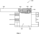
- the housing 550 comprises a first locating post 503 and a second locating post 504. At least the first locating post defines internal threads 505 such that the first and second locating posts function to locate the housing 550 relative to a circuit board and the internal threads function to receive a fastener 506 and secure the housing to the circuit board.
- This embodiment utilizing the threaded locating post offers advantages. For example, depending on the circuit board thickness, the fastener securing the connector to the circuit board does not protrude into otherwise utilized space within the connector housing. Also the fastener may be fully contained within the circuit board.
Landscapes
- Physics & Mathematics (AREA)
- General Physics & Mathematics (AREA)
- Optics & Photonics (AREA)
- Mechanical Coupling Of Light Guides (AREA)
Claims (12)
- Verbinder (100), der Folgendes umfasst:ein Gehäuse (101), das mehrere Aderendhülsenöffnungen (102) definiert, die in einer Matrix aus Reihen und Spalten angeordnet und zum Aufnehmen von Aderendhülsen (103) konfiguriert sind, wobei ein Teil der genannten Aderendhülsenöffnungen periphere Öffnungen (102a) sind und mindestens eine der genannten Aderendhülsenöffnungen eine innere Öffnung (102b) ist, wobei sich die genannte mindestens eine innere Öffnung (102b) zwischen zwei Spalten und zwischen zwei Reihen der genannten Matrix befindet; undmindestens zwei Halterkomponenten (105a, 105b), die mehrere Aderendhülsenhalteröffnungen (106) definieren, die mit den genannten mehreren Aderendhülsenöffnungen fluchten und zum Erleichtern des Durchgangs von Kabeln (104) von in den genannten Aderendhülsenöffnungen angeordneten Aderendhülsen durch sie konfiguriert sind,wobei die genannten mehreren Aderendhülsenhalteröffnungen (106) mindestens eine innere Halteröffnung (106b) beinhalten, die mit der genannten mindestens einen inneren Öffnung (102b) fluchtet, wobei jede der genannten mindestens zwei Halterkomponenten eine Peripherie (110a, 110b) und einen Teil der genannten mehreren Aderendhülsenhalteröffnungen (106) definiert und einen Zugangsweg (107, 107a) von der genannten Peripherie zu jedem genannten Teil der genannten mehreren Aderendhülsenhalteröffnungen (106) definiert, um den Durchgang eines Kabels durch den Zugangsweg zu ermöglichen, und wobei die genannten mindestens zwei Halterkomponenten an ihrer Peripherie so zusammenfügbar sind, dass kein Zugang von den genannten Zugangswegen (107a) zu der genannten inneren Halteröffnung (106b) verfügbar ist.
- Verbinder (100) nach Anspruch 1, wobei der genannte Teil der genannten Aderendhülsenhalteröffnungen (106) mehr als eine Aderendhülsenhalteöffnung umfasst.
- Verbinder (100) nach Anspruch 2, wobei jede der genannten Aderendhülsenhalteröffnungen (106) oder ein Teil davon entlang der Peripherie (110a, 110b) von einer der genannten Halterkomponenten (105a, 105b) definiert ist.
- Verbinder (100) nach Anspruch 2, wobei jede der genannten Halterkomponenten (105a, 105b) einen Teil der genannten mindestens einen inneren Halteröffnung (106b) definiert, so dass die genannten Halterkomponenten des genannten Halters (105) die genannte mindestens eine innere Halteröffnung (106b) vervollständigen.
- Verbinder (100) nach Anspruch 4, wobei jede der genannten Aderendhülsenhalteröffnungen (106) oder ein Teil davon entlang der Peripherie (110a, 110b) von einer der genannten Halterkomponenten (105a, 105b) definiert ist.
- Verbinder (100) nach Anspruch 1, wobei die genannten zwei oder mehr Halterkomponenten (105a, 105b) zwei Halterkomponenten umfassen.
- Verbinder (100) nach Anspruch 6, wobei die genannten zwei Halterkomponenten (105a, 105b) hermaphroditisch sind.
- Verbinder (100) nach Anspruch 7, wobei die genannten zwei Halterkomponenten (105a, 105b) miteinander verbindbar sind.
- Verbinder (100) nach Anspruch 8, wobei die genannten zwei Halterkomponenten (105a, 105b) mit dem genannten Gehäuse (101) mit einem oder mehreren Befestigungselementen (111a, 111b) verbindbar sind.
- Verbinder (100) nach Anspruch 1, wobei ein aus zwei oder mehr der genannten Halterkomponenten (105a, 105b) zusammengefügter Halter (105) Ausrichtungsmontagelöcher zur Aufnahme von Montagebefestigungselementen (111a, 111b) definiert.
- Verbinder (100) nach Anspruch 1, wobei das genannte Gehäuse (101) einen ersten Positionierungspfosten (503) und einen zweiten Positionierungspfosten (504) umfasst, wobei zumindest der genannte erste Positionierungspfosten ein Innengewinde (505) definiert, so dass der genannte erste und zweite Positionierungspfosten dazu dienen, das Gehäuse relativ zu einer Leiterplatte (502) zu positionieren, und das genannte Innengewinde dazu dient, ein oder mehrere Befestigungsmittel (506) zum Befestigen des genannten Gehäuses an der genannten Leiterplatte aufzunehmen.
- Verbinder (100) nach Anspruch 1, der ferner mehrere Aderendhülsen und ein an jede Aderendhülse angeschlossenes optisches Kabel umfasst, wobei jede der genannten mehreren Aderendhülsen in einer der genannten mehreren Aderendhülsenöffnungen (102) in dem genannten Gehäuse (101) angeordnet ist und das genannte optische Kabel jeder Aderendhülse in einer der genannten mehreren Aderendhülsenhalteröffnungen (106) entsprechend der genannten einen der genannten mehreren Aderendhülsenöffnungen angeordnet ist.
Applications Claiming Priority (2)
| Application Number | Priority Date | Filing Date | Title |
|---|---|---|---|
| US15/487,042 US10359579B2 (en) | 2017-04-13 | 2017-04-13 | Multi-ferrule connector |
| PCT/IB2018/052589 WO2018189720A1 (en) | 2017-04-13 | 2018-04-13 | Multi-ferrule connector |
Publications (2)
| Publication Number | Publication Date |
|---|---|
| EP3610310A1 EP3610310A1 (de) | 2020-02-19 |
| EP3610310B1 true EP3610310B1 (de) | 2023-04-26 |
Family
ID=62092192
Family Applications (1)
| Application Number | Title | Priority Date | Filing Date |
|---|---|---|---|
| EP18721479.6A Active EP3610310B1 (de) | 2017-04-13 | 2018-04-13 | Mehrfachferrulensteckverbinder |
Country Status (3)
| Country | Link |
|---|---|
| US (1) | US10359579B2 (de) |
| EP (1) | EP3610310B1 (de) |
| WO (1) | WO2018189720A1 (de) |
Families Citing this family (6)
| Publication number | Priority date | Publication date | Assignee | Title |
|---|---|---|---|---|
| CN115668019A (zh) * | 2020-05-26 | 2023-01-31 | 住友电气工业株式会社 | 光装置、光连接器以及光装置的制造方法 |
| US11506847B2 (en) * | 2020-07-23 | 2022-11-22 | Te Connectivity Solutions Gmbh | Modularized insert assembly for backplane connector |
| WO2022059645A1 (ja) * | 2020-09-16 | 2022-03-24 | 住友電気工業株式会社 | 光配線および光接続方法 |
| US12176792B2 (en) * | 2022-03-30 | 2024-12-24 | Illinois Tool Works Inc. | Engine-driven generators and power systems having generator housing alignment and locating hardware |
| US12510720B2 (en) | 2022-07-05 | 2025-12-30 | Corning Research & Development Corporation | Connection interface for fiber optic cable assemblies and method of making such cable assemblies |
| WO2024189599A1 (en) * | 2023-03-15 | 2024-09-19 | Te Connectivity Solutions Gmbh | Daughter-card optical backplane connector system |
Family Cites Families (12)
| Publication number | Priority date | Publication date | Assignee | Title |
|---|---|---|---|---|
| DE3129489A1 (de) | 1981-07-27 | 1983-02-10 | Siemens AG, 1000 Berlin und 8000 München | Aufteilungsmuffe |
| US4875755A (en) | 1986-09-15 | 1989-10-24 | Tsi Incorporated | Fiber optic connector assembly and method of making same |
| CA2294930A1 (en) * | 1997-06-24 | 1998-12-30 | Siemens Electromechanical Components Gmbh & Co. Kg | Ferrule container for holding a multiple optical fiber arranged in a ferrule, and a connecting arrangement for connecting multiple optical fibers |
| JP2000081541A (ja) * | 1998-06-29 | 2000-03-21 | Yazaki Corp | 光ファイバコネクタ |
| US6259856B1 (en) * | 1999-03-04 | 2001-07-10 | Lucent Technologies, Inc. | Small form factor multi-fiber optical connectors and methods for making same |
| CN101124500B (zh) * | 2004-12-20 | 2010-07-14 | 莫莱克斯公司 | 光纤末端组件 |
| DE202006008655U1 (de) | 2006-05-30 | 2006-08-03 | CCS Technology, Inc., Wilmington | Kabelmuffe zur strukturierten Ablage bzw. Handhabung von in Lichtwellenleiterkabeln geführten Lichtwellenleitern |
| US8403570B2 (en) | 2008-04-10 | 2013-03-26 | Amphenol Corporation | Plural fiber optic interconnect |
| US9507098B2 (en) | 2012-03-08 | 2016-11-29 | Tyco Electronics Corporation | Multi-fiber connector with ferrule float |
| US9354399B2 (en) | 2012-08-07 | 2016-05-31 | Molex, Llc | Optical fiber connector assembly |
| US9207454B1 (en) * | 2013-03-15 | 2015-12-08 | Cadence Design Systems, Inc. | System and method for dust contamination prevention and removal in fiber-optic panel-mount assemblies |
| US10241278B2 (en) * | 2016-12-13 | 2019-03-26 | Te Connectivity Corporation | High density fiber-optic connector |
-
2017
- 2017-04-13 US US15/487,042 patent/US10359579B2/en active Active
-
2018
- 2018-04-13 EP EP18721479.6A patent/EP3610310B1/de active Active
- 2018-04-13 WO PCT/IB2018/052589 patent/WO2018189720A1/en not_active Ceased
Also Published As
| Publication number | Publication date |
|---|---|
| EP3610310A1 (de) | 2020-02-19 |
| US20180299625A1 (en) | 2018-10-18 |
| US10359579B2 (en) | 2019-07-23 |
| WO2018189720A1 (en) | 2018-10-18 |
Similar Documents
| Publication | Publication Date | Title |
|---|---|---|
| EP3610310B1 (de) | Mehrfachferrulensteckverbinder | |
| US8827568B1 (en) | Fiber optic connector adapter module assemblies and methods | |
| US5297227A (en) | Disengagable adapter for an optical fiber connection | |
| US6434316B1 (en) | Fiber optic connector | |
| US9261653B2 (en) | Fiber optic plug assembly and optical connector system | |
| US20140241689A1 (en) | Ganged fiber optic connector adapter modules and assemblies having reinforcement members and staggered fiber optic connector adapter ports | |
| EP3555683B1 (de) | Hochdichter glasfaserverbinder | |
| EP2899577B1 (de) | Adapteranordnung für LC-Glasfaserkabel | |
| US20080166090A1 (en) | Flexible optical interconnection system | |
| KR20020001575A (ko) | 광섬유 커넥터 | |
| EP1172673A2 (de) | Ausrichtungssystem für faseroptische Stecker | |
| EP2951630B1 (de) | Glasfaserverbindungssystem | |
| US9086546B2 (en) | Connector systems having receptacle assembly and plug assembly | |
| US20050041926A1 (en) | Panel assembly with dense fiber output array | |
| US9678294B2 (en) | Optical fiber connection apparatus | |
| CA1295427C (en) | Printed circuit card guide | |
| US6434315B1 (en) | Fiber optic connector | |
| US20130016947A1 (en) | Photonic assembly for optical fibers | |
| US8070366B1 (en) | Optical fiber connector and method | |
| US20100316345A1 (en) | Fiber optic panel and method | |
| US4718861A (en) | Detachable cable strain relief clamp | |
| US11662531B2 (en) | Ferrule holder assembly | |
| CA2060731A1 (en) | Optical fiber distribution module | |
| US11437792B2 (en) | Cable management assembly for cable manager and cable manager | |
| EP4202515A1 (de) | Faseroptisches modul mit hochzugänglichen anschlüssen |
Legal Events
| Date | Code | Title | Description |
|---|---|---|---|
| STAA | Information on the status of an ep patent application or granted ep patent |
Free format text: STATUS: UNKNOWN |
|
| STAA | Information on the status of an ep patent application or granted ep patent |
Free format text: STATUS: THE INTERNATIONAL PUBLICATION HAS BEEN MADE |
|
| PUAI | Public reference made under article 153(3) epc to a published international application that has entered the european phase |
Free format text: ORIGINAL CODE: 0009012 |
|
| STAA | Information on the status of an ep patent application or granted ep patent |
Free format text: STATUS: REQUEST FOR EXAMINATION WAS MADE |
|
| 17P | Request for examination filed |
Effective date: 20191107 |
|
| AK | Designated contracting states |
Kind code of ref document: A1 Designated state(s): AL AT BE BG CH CY CZ DE DK EE ES FI FR GB GR HR HU IE IS IT LI LT LU LV MC MK MT NL NO PL PT RO RS SE SI SK SM TR |
|
| AX | Request for extension of the european patent |
Extension state: BA ME |
|
| DAV | Request for validation of the european patent (deleted) | ||
| DAX | Request for extension of the european patent (deleted) | ||
| STAA | Information on the status of an ep patent application or granted ep patent |
Free format text: STATUS: EXAMINATION IS IN PROGRESS |
|
| 17Q | First examination report despatched |
Effective date: 20201030 |
|
| GRAP | Despatch of communication of intention to grant a patent |
Free format text: ORIGINAL CODE: EPIDOSNIGR1 |
|
| STAA | Information on the status of an ep patent application or granted ep patent |
Free format text: STATUS: GRANT OF PATENT IS INTENDED |
|
| INTG | Intention to grant announced |
Effective date: 20230104 |
|
| GRAS | Grant fee paid |
Free format text: ORIGINAL CODE: EPIDOSNIGR3 |
|
| GRAA | (expected) grant |
Free format text: ORIGINAL CODE: 0009210 |
|
| STAA | Information on the status of an ep patent application or granted ep patent |
Free format text: STATUS: THE PATENT HAS BEEN GRANTED |
|
| AK | Designated contracting states |
Kind code of ref document: B1 Designated state(s): AL AT BE BG CH CY CZ DE DK EE ES FI FR GB GR HR HU IE IS IT LI LT LU LV MC MK MT NL NO PL PT RO RS SE SI SK SM TR |
|
| REG | Reference to a national code |
Ref country code: GB Ref legal event code: FG4D |
|
| REG | Reference to a national code |
Ref country code: CH Ref legal event code: EP |
|
| REG | Reference to a national code |
Ref country code: DE Ref legal event code: R096 Ref document number: 602018048877 Country of ref document: DE |
|
| REG | Reference to a national code |
Ref country code: AT Ref legal event code: REF Ref document number: 1563249 Country of ref document: AT Kind code of ref document: T Effective date: 20230515 |
|
| REG | Reference to a national code |
Ref country code: IE Ref legal event code: FG4D |
|
| REG | Reference to a national code |
Ref country code: LT Ref legal event code: MG9D |
|
| REG | Reference to a national code |
Ref country code: NL Ref legal event code: MP Effective date: 20230426 |
|
| REG | Reference to a national code |
Ref country code: AT Ref legal event code: MK05 Ref document number: 1563249 Country of ref document: AT Kind code of ref document: T Effective date: 20230426 |
|
| RAP2 | Party data changed (patent owner data changed or rights of a patent transferred) |
Owner name: TE CONNECTIVITY SOLUTIONS GMBH |
|
| PG25 | Lapsed in a contracting state [announced via postgrant information from national office to epo] |
Ref country code: NL Free format text: LAPSE BECAUSE OF FAILURE TO SUBMIT A TRANSLATION OF THE DESCRIPTION OR TO PAY THE FEE WITHIN THE PRESCRIBED TIME-LIMIT Effective date: 20230426 |
|
| PG25 | Lapsed in a contracting state [announced via postgrant information from national office to epo] |
Ref country code: SE Free format text: LAPSE BECAUSE OF FAILURE TO SUBMIT A TRANSLATION OF THE DESCRIPTION OR TO PAY THE FEE WITHIN THE PRESCRIBED TIME-LIMIT Effective date: 20230426 Ref country code: PT Free format text: LAPSE BECAUSE OF FAILURE TO SUBMIT A TRANSLATION OF THE DESCRIPTION OR TO PAY THE FEE WITHIN THE PRESCRIBED TIME-LIMIT Effective date: 20230828 Ref country code: NO Free format text: LAPSE BECAUSE OF FAILURE TO SUBMIT A TRANSLATION OF THE DESCRIPTION OR TO PAY THE FEE WITHIN THE PRESCRIBED TIME-LIMIT Effective date: 20230726 Ref country code: ES Free format text: LAPSE BECAUSE OF FAILURE TO SUBMIT A TRANSLATION OF THE DESCRIPTION OR TO PAY THE FEE WITHIN THE PRESCRIBED TIME-LIMIT Effective date: 20230426 Ref country code: AT Free format text: LAPSE BECAUSE OF FAILURE TO SUBMIT A TRANSLATION OF THE DESCRIPTION OR TO PAY THE FEE WITHIN THE PRESCRIBED TIME-LIMIT Effective date: 20230426 |
|
| PG25 | Lapsed in a contracting state [announced via postgrant information from national office to epo] |
Ref country code: RS Free format text: LAPSE BECAUSE OF FAILURE TO SUBMIT A TRANSLATION OF THE DESCRIPTION OR TO PAY THE FEE WITHIN THE PRESCRIBED TIME-LIMIT Effective date: 20230426 Ref country code: PL Free format text: LAPSE BECAUSE OF FAILURE TO SUBMIT A TRANSLATION OF THE DESCRIPTION OR TO PAY THE FEE WITHIN THE PRESCRIBED TIME-LIMIT Effective date: 20230426 Ref country code: LV Free format text: LAPSE BECAUSE OF FAILURE TO SUBMIT A TRANSLATION OF THE DESCRIPTION OR TO PAY THE FEE WITHIN THE PRESCRIBED TIME-LIMIT Effective date: 20230426 Ref country code: LT Free format text: LAPSE BECAUSE OF FAILURE TO SUBMIT A TRANSLATION OF THE DESCRIPTION OR TO PAY THE FEE WITHIN THE PRESCRIBED TIME-LIMIT Effective date: 20230426 Ref country code: IS Free format text: LAPSE BECAUSE OF FAILURE TO SUBMIT A TRANSLATION OF THE DESCRIPTION OR TO PAY THE FEE WITHIN THE PRESCRIBED TIME-LIMIT Effective date: 20230826 Ref country code: HR Free format text: LAPSE BECAUSE OF FAILURE TO SUBMIT A TRANSLATION OF THE DESCRIPTION OR TO PAY THE FEE WITHIN THE PRESCRIBED TIME-LIMIT Effective date: 20230426 Ref country code: GR Free format text: LAPSE BECAUSE OF FAILURE TO SUBMIT A TRANSLATION OF THE DESCRIPTION OR TO PAY THE FEE WITHIN THE PRESCRIBED TIME-LIMIT Effective date: 20230727 |
|
| PG25 | Lapsed in a contracting state [announced via postgrant information from national office to epo] |
Ref country code: FI Free format text: LAPSE BECAUSE OF FAILURE TO SUBMIT A TRANSLATION OF THE DESCRIPTION OR TO PAY THE FEE WITHIN THE PRESCRIBED TIME-LIMIT Effective date: 20230426 |
|
| PG25 | Lapsed in a contracting state [announced via postgrant information from national office to epo] |
Ref country code: SK Free format text: LAPSE BECAUSE OF FAILURE TO SUBMIT A TRANSLATION OF THE DESCRIPTION OR TO PAY THE FEE WITHIN THE PRESCRIBED TIME-LIMIT Effective date: 20230426 |
|
| REG | Reference to a national code |
Ref country code: DE Ref legal event code: R097 Ref document number: 602018048877 Country of ref document: DE |
|
| PG25 | Lapsed in a contracting state [announced via postgrant information from national office to epo] |
Ref country code: SM Free format text: LAPSE BECAUSE OF FAILURE TO SUBMIT A TRANSLATION OF THE DESCRIPTION OR TO PAY THE FEE WITHIN THE PRESCRIBED TIME-LIMIT Effective date: 20230426 Ref country code: SK Free format text: LAPSE BECAUSE OF FAILURE TO SUBMIT A TRANSLATION OF THE DESCRIPTION OR TO PAY THE FEE WITHIN THE PRESCRIBED TIME-LIMIT Effective date: 20230426 Ref country code: RO Free format text: LAPSE BECAUSE OF FAILURE TO SUBMIT A TRANSLATION OF THE DESCRIPTION OR TO PAY THE FEE WITHIN THE PRESCRIBED TIME-LIMIT Effective date: 20230426 Ref country code: EE Free format text: LAPSE BECAUSE OF FAILURE TO SUBMIT A TRANSLATION OF THE DESCRIPTION OR TO PAY THE FEE WITHIN THE PRESCRIBED TIME-LIMIT Effective date: 20230426 Ref country code: DK Free format text: LAPSE BECAUSE OF FAILURE TO SUBMIT A TRANSLATION OF THE DESCRIPTION OR TO PAY THE FEE WITHIN THE PRESCRIBED TIME-LIMIT Effective date: 20230426 Ref country code: CZ Free format text: LAPSE BECAUSE OF FAILURE TO SUBMIT A TRANSLATION OF THE DESCRIPTION OR TO PAY THE FEE WITHIN THE PRESCRIBED TIME-LIMIT Effective date: 20230426 |
|
| PLBE | No opposition filed within time limit |
Free format text: ORIGINAL CODE: 0009261 |
|
| STAA | Information on the status of an ep patent application or granted ep patent |
Free format text: STATUS: NO OPPOSITION FILED WITHIN TIME LIMIT |
|
| 26N | No opposition filed |
Effective date: 20240129 |
|
| PG25 | Lapsed in a contracting state [announced via postgrant information from national office to epo] |
Ref country code: SI Free format text: LAPSE BECAUSE OF FAILURE TO SUBMIT A TRANSLATION OF THE DESCRIPTION OR TO PAY THE FEE WITHIN THE PRESCRIBED TIME-LIMIT Effective date: 20230426 |
|
| PG25 | Lapsed in a contracting state [announced via postgrant information from national office to epo] |
Ref country code: SI Free format text: LAPSE BECAUSE OF FAILURE TO SUBMIT A TRANSLATION OF THE DESCRIPTION OR TO PAY THE FEE WITHIN THE PRESCRIBED TIME-LIMIT Effective date: 20230426 Ref country code: IT Free format text: LAPSE BECAUSE OF FAILURE TO SUBMIT A TRANSLATION OF THE DESCRIPTION OR TO PAY THE FEE WITHIN THE PRESCRIBED TIME-LIMIT Effective date: 20230426 |
|
| PG25 | Lapsed in a contracting state [announced via postgrant information from national office to epo] |
Ref country code: BG Free format text: LAPSE BECAUSE OF FAILURE TO SUBMIT A TRANSLATION OF THE DESCRIPTION OR TO PAY THE FEE WITHIN THE PRESCRIBED TIME-LIMIT Effective date: 20230426 |
|
| PG25 | Lapsed in a contracting state [announced via postgrant information from national office to epo] |
Ref country code: MC Free format text: LAPSE BECAUSE OF FAILURE TO SUBMIT A TRANSLATION OF THE DESCRIPTION OR TO PAY THE FEE WITHIN THE PRESCRIBED TIME-LIMIT Effective date: 20230426 |
|
| PG25 | Lapsed in a contracting state [announced via postgrant information from national office to epo] |
Ref country code: MC Free format text: LAPSE BECAUSE OF FAILURE TO SUBMIT A TRANSLATION OF THE DESCRIPTION OR TO PAY THE FEE WITHIN THE PRESCRIBED TIME-LIMIT Effective date: 20230426 Ref country code: BG Free format text: LAPSE BECAUSE OF FAILURE TO SUBMIT A TRANSLATION OF THE DESCRIPTION OR TO PAY THE FEE WITHIN THE PRESCRIBED TIME-LIMIT Effective date: 20230426 |
|
| REG | Reference to a national code |
Ref country code: CH Ref legal event code: PL |
|
| PG25 | Lapsed in a contracting state [announced via postgrant information from national office to epo] |
Ref country code: LU Free format text: LAPSE BECAUSE OF NON-PAYMENT OF DUE FEES Effective date: 20240413 |
|
| REG | Reference to a national code |
Ref country code: BE Ref legal event code: MM Effective date: 20240430 |
|
| PG25 | Lapsed in a contracting state [announced via postgrant information from national office to epo] |
Ref country code: LU Free format text: LAPSE BECAUSE OF NON-PAYMENT OF DUE FEES Effective date: 20240413 |
|
| PG25 | Lapsed in a contracting state [announced via postgrant information from national office to epo] |
Ref country code: BE Free format text: LAPSE BECAUSE OF NON-PAYMENT OF DUE FEES Effective date: 20240430 |
|
| PG25 | Lapsed in a contracting state [announced via postgrant information from national office to epo] |
Ref country code: BE Free format text: LAPSE BECAUSE OF NON-PAYMENT OF DUE FEES Effective date: 20240430 Ref country code: CH Free format text: LAPSE BECAUSE OF NON-PAYMENT OF DUE FEES Effective date: 20240430 |
|
| PG25 | Lapsed in a contracting state [announced via postgrant information from national office to epo] |
Ref country code: IE Free format text: LAPSE BECAUSE OF NON-PAYMENT OF DUE FEES Effective date: 20240413 |
|
| PGFP | Annual fee paid to national office [announced via postgrant information from national office to epo] |
Ref country code: DE Payment date: 20250305 Year of fee payment: 8 |
|
| PG25 | Lapsed in a contracting state [announced via postgrant information from national office to epo] |
Ref country code: CY Free format text: LAPSE BECAUSE OF FAILURE TO SUBMIT A TRANSLATION OF THE DESCRIPTION OR TO PAY THE FEE WITHIN THE PRESCRIBED TIME-LIMIT; INVALID AB INITIO Effective date: 20180413 |
|
| PG25 | Lapsed in a contracting state [announced via postgrant information from national office to epo] |
Ref country code: HU Free format text: LAPSE BECAUSE OF FAILURE TO SUBMIT A TRANSLATION OF THE DESCRIPTION OR TO PAY THE FEE WITHIN THE PRESCRIBED TIME-LIMIT; INVALID AB INITIO Effective date: 20180413 |
|
| PGFP | Annual fee paid to national office [announced via postgrant information from national office to epo] |
Ref country code: GB Payment date: 20260313 Year of fee payment: 9 |
|
| PGFP | Annual fee paid to national office [announced via postgrant information from national office to epo] |
Ref country code: FR Payment date: 20260309 Year of fee payment: 9 |