EP3610312B1 - Câble de dérivation plat avec éléments pour une aptitude au dénudage améliorée - Google Patents
Câble de dérivation plat avec éléments pour une aptitude au dénudage améliorée Download PDFInfo
- Publication number
- EP3610312B1 EP3610312B1 EP18721619.7A EP18721619A EP3610312B1 EP 3610312 B1 EP3610312 B1 EP 3610312B1 EP 18721619 A EP18721619 A EP 18721619A EP 3610312 B1 EP3610312 B1 EP 3610312B1
- Authority
- EP
- European Patent Office
- Prior art keywords
- jacket
- fiber optic
- optic cable
- curvature
- radius
- Prior art date
- Legal status (The legal status is an assumption and is not a legal conclusion. Google has not performed a legal analysis and makes no representation as to the accuracy of the status listed.)
- Active
Links
Images





Classifications
-
- G—PHYSICS
- G02—OPTICS
- G02B—OPTICAL ELEMENTS, SYSTEMS OR APPARATUS
- G02B6/00—Light guides; Structural details of arrangements comprising light guides and other optical elements, e.g. couplings
- G02B6/44—Mechanical structures for providing tensile strength and external protection for fibres, e.g. optical transmission cables
- G02B6/4401—Optical cables
- G02B6/4429—Means specially adapted for strengthening or protecting the cables
- G02B6/443—Protective covering
- G02B6/4432—Protective covering with fibre reinforcements
- G02B6/4433—Double reinforcement laying in straight line with optical transmission element
-
- G—PHYSICS
- G02—OPTICS
- G02B—OPTICAL ELEMENTS, SYSTEMS OR APPARATUS
- G02B6/00—Light guides; Structural details of arrangements comprising light guides and other optical elements, e.g. couplings
- G02B6/44—Mechanical structures for providing tensile strength and external protection for fibres, e.g. optical transmission cables
- G02B6/4401—Optical cables
- G02B6/4429—Means specially adapted for strengthening or protecting the cables
- G02B6/443—Protective covering
- G02B6/4431—Protective covering with provision in the protective covering, e.g. weak line, for gaining access to one or more fibres, e.g. for branching or tapping
Definitions
- the present disclosure relates generally to fiber optic cables. More particularly, the present disclosure relates to flat drop cables.
- a fiber optic cable typically includes: (1) an outer jacket; (2) a core including at least one optical fiber positioned within the jacket; and (3) a plurality of strength members positioned around or incorporated into the core.
- the optical fiber functions to carry optical signals.
- a typical optical fiber includes an inner core surrounded by a cladding that is protected by a coating layer.
- the core can also include a buffer layer that functions to surround and protect the coated optical fiber.
- the buffer layer can include a tight buffer layer, a semi-tight buffer layer, or a loose buffer layer.
- the strength members of the fiber optic cable such as aramid yarns, like the yarns sold under the trademark KEVLAR®, add mechanical reinforcement to the fiber optic cable to protect the internal optical fiber against stresses applied to the cable during installation and thereafter.
- the strength members can also assist in attaching a connector to the cable when the cable is terminated.
- the outer jacket can be configured to protect the optical fiber by preventing the fiber from being exposed to outside elements.
- Drop cables used in fiber optic networks can be constructed with jackets each having a flat transverse cross-sectional profile.
- Such cables typically include at least one central buffer tube containing at least one optical fiber, and reinforcing members such as rods made of glass reinforced epoxy, like glass reinforced plastic (GRP) rods, embedded in the jacket on opposite sides of the buffer tube.
- GRP glass reinforced plastic
- US 2002/0122639 A1 describes an optical cable with continuous accessibility.
- WO 2015/109459 A1 describes a fiber optic cable comprising a jacket and an open-sided notch defined by the jacket that extends along the length of the jacket.
- the invention relates to a flat drop cable according to claim 1. Different embodiments are set out in the dependent claims.
- spatially relative terms such as “under”, “below”, “lower”, “over”, “upper”, “lateral”, “left”, “right” and the like, may be used herein for ease of description to describe one element or feature's relationship to another element(s) or feature(s) as illustrated in the figures. It will be understood that the spatially relative terms are intended to encompass different orientations of the device in use or operation in addition to the orientation depicted in the figures. For example, if the device in the figures is inverted, elements described as “under” or “beneath” other elements or features would then be oriented “over” the other elements or features. The device may be otherwise oriented (rotated 90 degrees or at other orientations) and the descriptors of relative spatial relationships used herein interpreted accordingly.
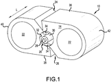
- FIGS 1 and 1A show a fiber optic cable 10 in accordance with the principles of the present disclosure.
- the fiber optic cable 10 includes a jacket 14, a core 20 disposed within the jacket 14, and cable reinforcing members 22 positioned within the jacket 14.
- the fiber optic cable 10 further includes structures for enhancing the stripability of the jacket 14 relative to the core 20. In the depicted example, such structures can include first and second notches 24, 26 defined within the jacket 14.
- the depicted fiber optic cable 10 is shown as a flat drop cable having a length L, a width W, and a thickness T.
- the fiber optic cable 10 includes a central longitudinal axis 12 that extends along the length L of the fiber optic cable 10.
- the jacket 14 of the cable 10 has a transverse cross-sectional profile that is elongated such that the width W is larger than the thickness T.
- the transverse cross-sectional profile of the jacket 14 defines a minor axis 16 that extends along the thickness T and a major axis 18 that extends along the width W.
- the minor and major axes 16, 18 are perpendicular relative to one another and intersect at the central longitudinal axis 12 of the fiber optic cable 10.
- the core 20 of the fiber optic cable 10 is centered generally along the central longitudinal axis 12.
- the cable reinforcing members 22 are positioned on opposite sides of the minor axis 16.
- the central longitudinal axis 12 is located precisely in the center of the core 20 which is also the center of fiber optic cable 10.
- the major axis 18 passes through the centers of the reinforcing members 22 and the core 20, and the minor axis 16 passes through the center of the core 20.
- the notches 24, 26 or other structures for enhancing the stripability of the jacket 14 relative to the core 20 are disposed at locations offset from the minor axis 16.
- the core 20 of the fiber optic cable 10 includes an optical fiber 28 and a buffer layer 30 that surrounds the optical fiber 28.
- the optical fiber 28 can include a core, a cladding layer surrounding the core, and one or more polymeric coatings surrounding the cladding layer.
- the buffer layer 30 can include a buffer tube such as a tight buffer tube, a loose buffer tube, or a semi-tight buffer tube.
- the core 20 may include more than one optical fiber 28.
- the core 20 extends along the entire length L of the fiber optic cable 10.
- the cable reinforcing members 22 extend along the length L of the fiber optic cable 10 and are aligned along the major axis 18 of the transverse cross-sectional profile of the fiber optic cable 10. More particularly, the major axis 18 passes through the centers of the cable reinforcing members 22 so as to follow diameters of the cable reinforcing members 22. As depicted, the cable reinforcing members 22 are positioned on opposite sides of the minor axis 16 of the transverse cross-sectional profile of the fiber optic cable 10 and spaced equal distances away from the minor axis 16. In certain examples, the cable reinforcing members 22 can be configured to provide the fiber optic cable 10 with both tensile and compressive reinforcement. In certain examples, cable reinforcing members 22 can have a construction that includes epoxy reinforced with fiberglass. In other examples, the cable reinforcing members 22 can include Aramid yarn, metal rods, GRP rods or other structures.
- the jacket 14 defines a central passage 32 in which the core 20 is positioned.
- strength members 34 such as water soluble fiberglass strands, can be provided in the central passage 32.
- strength members 34 such as numerous aramid yarns like KEVLAR®, can be provided in the central passage surrounding the buffer layer 30.
- the strength members 34 can prevent the core 20 from sticking to or being contacted by the jacket 14. In this way, fiber performance will not be affected by strain applied to the jacket 14.
- the jacket 14 includes polyethylene.
- central passage 32 is larger than the core 20 such that the core is loosely provided within the central passage 32.
- the strength members 34 assist in centering the core 20 within the central passage 32 and in preventing the core 20 from adhering to the jacket 14 during extrusion.
- the strength members 34 can include a water soluble material that swells when exposed to water so as to inhibit the intrusion of water along the central passage 32.
- the jacket 14 of the fiber optic cable 10 includes opposite top and bottom sides 36, 38 that extend between opposite rounded ends 40, 42.
- the thickness T of the fiber optic cable 10 extends between the top and bottom sides 36, 38 while the width W of the fiber optic cable 10 extends between the rounded ends 40, 42.
- the top and bottom sides 36, 38 are generally parallel and flat.
- the notches 24, 26 are provided for facilitating stripping the jacket 14 from the core 20. As shown in Figures 1 and 2 , the notch 24 is provided at the top side 36 of the jacket 14 and the notch 26 is provided at the bottom side 38 of the jacket 14.
- the notches 24, 26 have lengths that extend along the length L of the fiber optic cable 10.
- Each of the notches 24, 26 includes an open end 44 positioned at an exterior boundary 46 of the jacket 14 and a closed end 48 within an interior of the jacket 14.
- the open end 44 has a cross dimension CD that is larger than a corresponding cross dimension of the closed end 48.
- closed end 48 is defined by an inner edge 48 having a cross dimension of essentially zero.
- each of the notches 24, 26 has an angled or tapered configuration when viewed in transverse cross-section.
- each of the notches 24, 26 can be defined by surfaces 50, 52 that converge as the surfaces 50, 52 extend in a direction from the open end 44 to the closed end 48.
- the closed ends 48 are defined by the inner edges 49 formed by the intersection of the surfaces 50, 52.
- the notches 24, 26 are offset from the minor axis 16 and are positioned on opposite sides of the minor axis 16.
- the notch 24 is positioned between the minor axis 16 and the rounded end 40 of the jacket 14 while the notch 26 is positioned between the minor axis 16 and the rounded end 42 of the jacket 14.
- the notches 24 and 26 extend into a central boundary 56 defined between a first reference plane 58 (depicted in FIGS. 1A and 2 as a vertical line) and a second reference plane 60 (depicted in FIGS. 1A and 2 as a vertical line).
- the first reference plate 58 is positioned on one side of the minor axis 16 and is tangent to the core 20.
- the second reference plane 60 is positioned on an opposite side of the minor axis 16 and is tangent to the core 20.
- the first and second reference planes 58, 60 are perpendicular relative to the major axis 18.
- the notches 24, 26 are formed by surfaces 50' and 52' and are positioned completely outside of the central boundary 56.
- Suitable positioning of the inner edges 49 of the notches 24, 26 can facilitate stripping the jacket 14 from the core 20 and accessing the core 20 after stripping.
- the inner edges 49 are positioned along a reference plane P, P' that intersects the core 20.
- the reference plane P, P' intersects the inner edges 49 and also intersects the central longitudinal axis 12 of the core 20.
- the notches 24, 26 form a tear path aligned along the reference plane P, P'.
- a diagonal tear path is defined between the inner edges 49 of the notches 24, 26 along the reference plane P, P'.
- the diagonal tear path 49 intersects the core 20.
- the jacket 14 is provided with only one diagonal tear path.
- the notches 24, 26 are laterally offset from one another so that the inner edges 49 are not positioned along a reference plane that is perpendicular relative to the major axis 18.
- only one notch 24 is provided at the top side 36 of the jacket 14 and only one notch 26 is provided at the bottom side 38 of the jacket 14; the notches 24, 26 are provided on opposite sides of the minor axis 16.
- the surfaces 50, 52 defining the notches 24, 26 are oriented at oblique angles relative to one another and intersect at inner edges 49.
- the inner edges 49 are offset from the minor axis 16.
- the inner edges 49 of the notches 24, 26 are offset on opposite sides of the minor axis 16 from one another by equal distances.
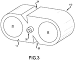
- FIG 3 shows another fiber optic cable 110 in accordance with the principles of the present disclosure.
- the fiber optic cable 110 has the same basic configuration as the fiber optic cable 10 except the jacket 14 is tightly extruded about the core 20 and no strength members 34 are provided between the core 20 and the jacket 14.
- FIG. 4 illustrates a further fiber optic cable 210 in accordance with the principles of the present disclosure.
- the fiber optic cable 210 includes top and bottom notches 24, 26 positioned on the same side of the minor axis 16.
- the notches 24, 26 are aligned along a reference plane 62 that does not intersect the core 20.
- the reference plane 62 is perpendicular relative to the major axis 18 and parallel to the minor axis 16.
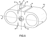
- FIG. 5 illustrates still another fiber optic cable 310 in accordance with the principles of the present disclosure.
- the fiber optic cable 310 includes two sets of notches 24, 26 positioned on opposite sides of the minor axis 16.
- the notches 24, 26 of the first set are positioned along a reference plane 64 that is offset to the left of the minor axis 16 while the notches 24, 26 of the second set of notches is provided along a reference plane 66 that is offset to the right of the minor axis 16.
- the reference planes 64, 66 do not intersect the core 20 and are perpendicular relative to the major axis 18 and parallel to the minor axis 16.
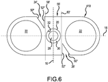
- FIG. 6 illustrates a further fiber optic cable 410 in accordance with the principles of the present disclosure.
- the fiber optic cable 410 includes top and bottom notches 24', 26' positioned on opposite sides of a central boundary 56' defined between a first reference plane 58' and a second reference plane 60' positioned on opposite sides of and tangent to the central passage 32.
- the notches 24', 26' are offset from the central boundary 56'.
- Each of the notches 24', 26' has a first side 50" that converges with a second side 52" as the sides 50", 52" extend into the jacket 14.
- the second side 52" of each notch 24', 26' extends generally parallel with the minor axis 16 of the cable 410.
- the second side 52" of each notch 24', 26' extends generally orthogonal with the major axis 18 of the cable 410.
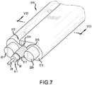
- Figure 7 is a perspective view of a fiber optic cable 510 according to a final embodiment of the present disclosure.
- Figure 8 is a cross section view taken along line VIII -- VIII in Figure 7 depicting various dimensions and angles.
- Figure 9 is the same cross sectional view as Figure 8 , but depicting radius of curvatures and additional dimensions.
- the fiber optic cable 510 is similar to the embodiment depicted in Figure 2 , as discussed above.
- a jacket 513 surrounds the first and second reinforcing members 22 and 22A and a core 511.
- the fiber optic cable 510 has a central longitudinal axis 12.
- the length of the jacket 513 extends along the direction of the central longitudinal axis 12 of the fiber optic cable 510.
- the jacket 513 defines a transverse cross-sectional profile ( Figures 8 and 9 ) having a thickness T and a width W.
- the thickness T may be in the range of 2.4 mm to 3.7 mm, such as in the range of 2.7 mm to 3.0 mm, and the width W may be in the range of 5 mm to 7 mm, such as in the range of 5.7 mm to 6.0 mm.
- the thickness T is smaller than the width W.
- a periphery thickness B of the jacket 513 surrounding the first and second reinforcing members 22 and 22A might be approximately 0.4 to 0.6 mm, such as 0.5 to 0.55 mm.
- the transverse cross-sectional profile ( Figure 8 ) of the jacket 513 defines a major axis 18 that extends across the width W of the jacket 513 and a minor axis 16 that extends across the thickness T of the jacket 513.
- the major axis 18 is perpendicular to the minor axis 16.
- Both the major axis 18 and the minor axis 16 are perpendicular to the central longitudinal axis 12 of the fiber optic cable 510.
- the major axis 18 and the minor axis 16 intersect each other at the central longitudinal axis12.
- the first and second reinforcing members 22 and 22A are centered on the major axis 18, i.e., the major axis passes through the centers of the first and second reinforcing members 22 and 22A.
- the centers of the first and second reinforcing members 22 and 22A are located equal distances apart from the minor axis 16 on opposite sides of the minor axis 16.
- the closest side of the first strength member 22 to the closest edge of the core 511 as a distance A, which could be in the range of 0.20 mm to 0.55 mm, such as in the range of 0.25 mm to 0.5 mm, such as 0.30 mm to 0.45mm.
- the central axis 12 may also coincide with the center of the core 511.
- the core 511 is positioned within the jacket 513 and extends along the central longitudinal axis 12.
- the core 511 includes at least one optical fiber 28 surrounded by a buffer 30.
- the buffer 30 resides within a circular, cylindrical channel 515 formed within the jacket 513, with the center of the circular, cylindrical channel 515 coinciding with the central longitudinal axis 12.
- the buffer 30 may have a diameter of 0.9 mm and tightly surround the optical fiber 28.
- a plurality of strength members 517 such as aramid yarns, like those sold under the trademark KEVLAR® may reside between an inner wall of the circular, cylindrical channel 515 and the core 511.
- the strength members 517 may be formed as plural water blocking elements.
- a first open-sided notch 512 is formed in the jacket 513.
- the first open-sided notch 512 extends along the length L of the jacket 513.
- the first open-sided notch 512 is positioned at a location offset from the minor axis 16, wherein the first open-sided notch 512 includes an inner portion closest to the core and the inner portion is formed as a rounded valley 514.
- the first open-sided notch 512 is provided in a part of the jacket 513 outside of an area 516 between first and second lines 518 and 520 that are tangent to the core 511 and that are perpendicular to the major axis 18.
- the first open-sided notch 512 is defined by first and second surfaces 522 and 524 that are formed at an oblique angle relative to one another and that converge as the first and second surfaces 522 and 524 extend into the jacket 513 to attach to sides of the first rounded valley 514.
- the oblique angle between the first and second surfaces 522 and 524 is denoted by the combination of angles ⁇ 4 and ⁇ 5.
- the oblique angle ⁇ 4 and ⁇ 5 between the first and second surfaces 522 and 524 may reside between 35 degrees and 70 degrees, such as between 45 degrees and 60 degrees.
- angle ⁇ 4 exists between a vertical line VL (perpendicular to the major axis 18) and the second surface 524.
- Angle ⁇ 5 exists between the vertical line VL and the first surface 522.
- Angle ⁇ 4 is between 5 to 15 degrees and angle ⁇ 5 is between 40 to 45 degrees.
- angle ⁇ 4 is about one third of angle ⁇ 5.
- the fiber optic cable 510 also includes a second open-sided notch 512A formed in the jacket 513 that extends along the length of the jacket 513.
- the second open-sided notch 512A is positioned at a location offset from the minor axis 16, wherein the second open-sided notch 512A includes an inner portion closest to the core 511 and the inner portion is formed as a second rounded valley 514A.
- the second open-sided notch 512A is defined by third and fourth surfaces 524A and 522A that are formed at an oblique angle ( ⁇ 4 combined with ⁇ 5) relative to one another and that converge as the third and fourth surfaces 524A and 522A extend into the jacket to attach to sides of the second rounded valley 514A.
- the second open-sided notch 512A is mirror symmetrical to the first open-sided notch 512, if the mirror passes through the central longitudinal axis 12 at a 45 degree angle relative to the major axis 18.
- the jacket 513 defines first and second sides 527 and 529 separated by the thickness T and first and second rounded ends 528 and 530 separated by the width W.
- the first open-sided notch 512 is formed in the first side 527 of the jacket 513 between the minor axis 16 and the first rounded end 528 of the jacket 513.
- the second open-sided notch 512A is formed in the second side 529 of the jacket 513 between the minor axis 16 and the second rounded end 530.
- the first rounded valley 514 has a first radius of curvature and the second rounded valley 514A has a second radius of curvature.
- a first line P1 passes through a center C1 of the first radius of curvature and passes through a center C2 of the second radius of curvature also passes through the central longitudinal axis 12 of the fiber optic cable 510.
- the first radius of curvature is between 0.05 mm and 0.2 mm and wherein the second radius of curvature is between 0.05 mm and 0.2 mm.
- the first radius of curvature equals the second radius of curvature, and both are at least 0.1 mm.
- the first line PI forms a first angle ⁇ 2 relative to the major axis 18 of the fiber optic cable 510.
- the first angle is between 40 to 60 degrees.
- the first angle ⁇ 2 is between 47 to 50 degrees.
- the first side 527 is flat except for the first open-sided notch 512
- the second side 529 is flat except for the second open-sided notch 512A.
- a first shoulder 531 is formed between the first surface 522 and the flat first side 527 of the jacket 513.
- the first shoulder 531 has a third radius of curvature.
- a second shoulder 533 is formed between the second surface 524 and the flat first side 527 of the jacket 513.
- the second shoulder 533 has a fourth radius of curvature.
- the third radius of curvature is at least 0.2 mm and the fourth radius of curvature is at least 0.1 mm.
- the distance between the first shoulder and the second shoulder is in the range of 0.75 to 1.1 mm, such as between 0.85 and 1.00 mm.
- a third shoulder 533A is formed between the third surface 524A and the flat second side 529 of the jacket 513.
- the third shoulder 533A has a fifth radius of curvature.
- a fourth shoulder 531A is formed between the fourth surface 522A and the flat second side 529 of the jacket 513.
- the fourth shoulder 531A has a sixth radius of curvature.
- the third radius of curvature is equal to the sixth radius of curvature and the fourth radius of curvature is equal to the fifth radius of curvature.
- the first, second fourth and fifth radiuses of curvature are approximately equal to a first value
- the third and sixth radiuses of curvature are approximately twice the first value.
- a second line P2 passes through a center C3 of the third radius of curvature and passes through a center C6 of the sixth radius of curvature and also passes through the central longitudinal axis 12 of the fiber optic cable 510.
- a third line P3 passes through a center C4 of the fourth radius of curvature and passes through a center C5 of the fifth radius of curvature and also passes through the central longitudinal axis 12 of the fiber optic cable 510.
- the second line P2 forms a second angle ⁇ 3 relative to the major axis 18 of the fiber optic cable 510. In one embodiment, the second angle ⁇ 3 is between 25 to 50 degrees, such as between 35 to 40 degrees.
- the third line P3 forms a third angle ⁇ 1 relative to the major axis 18 of the fiber optic cable 510. In one embodiment, the third angle ⁇ 1 is between 60 to 85 degrees, such as between 70 to 75 degrees.
- FIG 10 is a perspective view of a modified fiber optic cable 510', similar to the fiber optic cable 510 of Figure 7 .
- the modified fiber optic cable 510' may be identically formed, except for the addition of a messenger wire 540.
- the messenger wire 540 may include a copper or copper-clad-steel wire 542 surrounded by a messenger jacket 544.
- the messenger jacket 544 is connected to the first rounded end 528 by a web 546.
- the material used to form the messenger jacket 544, the web 546 and the jacket 513 is a common material, which is extruded at one time to form the modified fiber optic cable 510'.
- the positioning and dimensioning of the centers C1, C2, C3, C4, C5 and C6 of the radius of curvatures relative to the overall fiber optic cable 510 assist in holding a gel around the cable 510.
- Typical gels used to seal cables interact with the curved surfaces and adhere to the curved surface and within the first and second open-sided notches 512 and 512A. Such gels may be used to seal the fiber optic cable 510 as it passes into an enclosure, such as the enclosure sold under the trademark TENIO® by the assignee of the present invention.
Landscapes
- Physics & Mathematics (AREA)
- General Physics & Mathematics (AREA)
- Optics & Photonics (AREA)
- Details Of Indoor Wiring (AREA)
- Light Guides In General And Applications Therefor (AREA)
Claims (14)
- Câble à fibres optiques (510) ayant un axe longitudinal central (12), le câble à fibres optiques (510) comprenant :une gaine (513) ayant une longueur (L), qui s'étend le long de l'axe longitudinal central (12) du câble à fibres optiques (510), la gaine (513) définissant un profil transversal en coupe transversale ayant une épaisseur (T) et une largeur (W), l'épaisseur (T) étant inférieure à la largeur (W), le profil transversal en coupe transversale de la gaine (513) définissant un axe principal (18) s'étendant sur la largeur (W) de la gaine (513) et un axe mineur (16) s'étendant sur l'épaisseur (T) de la gaine (513), l'axe principal et l'axe mineur (18, 16) étant perpendiculaires l'un à l'autre et étant également perpendiculaires à l'axe longitudinal central (12) du câble à fibres optiques (510), et l'axe principal (18) et l'axe mineur (16) se coupant au niveau de l'axe longitudinal central (12) ;un noyau (511) disposé à l'intérieur de la gaine (513) s'étendant le long de l'axe longitudinal central (12), le noyau (511) comprenant au moins une fibre optique (28) ;une première encoche à côtés ouverts formée dans la gaine (512), qui s'étend sur la longueur de la gaine (513), la première encoche à côtés ouverts (512) étant positionnée à un emplacement décalé par rapport à l'axe mineur (16), dans lequel la première encoche à côtés ouvert (512) comprend une partie intérieure la plus proche du noyau (511) et la partie intérieure est formée comme une première vallée arrondie (514), dans lequel la première encoche à côtés ouverts (512) est définie par des première et deuxième surfaces (522 et 524), qui sont formées à un angle oblique l'une par rapport à l'autre et qui convergent lorsque les première et deuxième surfaces (522 et 524) s'étendent dans la gaine (513) pour se fixer aux côtés de la première vallée arrondie (514); etune deuxième encoche à côtés ouverts (512A) formée dans la gaine (513), qui s'étend sur la longueur (L) de la gaine (513), la deuxième encoche à côté ouverts (512A) étant positionnée à un emplacement décalé par rapport à l'axe mineur (16), dans lequel la deuxième encoche à côté ouverts (512A) comprend une partie intérieure la plus proche du noyau (511) et la partie intérieure est formée comme une deuxième vallée arrondie (514A), dans lequel la deuxième encoche à côté ouverts (512A) est définie par des troisième et quatrième surfaces (524A et 522A), qui sont formées à un angle oblique l'une par rapport à l'autre et qui convergent lorsque les troisième et quatrième surfaces (524A et 522A) s'étendent dans la gaine (513) pour se fixer aux côtés de la deuxième vallée arrondie (512A),caractérisé en ce que
la première encoche à côté ouverts (512) a un premier rayon de courbure d'au moins 0. 1 mm configuré pour maintenir un gel dans la première encoche à côté ouverts (512) et la deuxième encoche à côté ouverts (512A) a un deuxième rayon de courbure d'au moins 0,1 mm pour maintenir un gel dans la deuxième encoche à côté ouverts (512A). - Câble à fibres optiques (510) selon la revendication 1, dans lequel la première encoche ouverte sur le côté (512) est prévue dans une partie de la gaine (513) à l'extérieur d'une zone entre les première et deuxième lignes (518 et 520), qui sont tangentes à l'âme (511) et qui sont perpendiculaires à l'axe principal (18).
- Câble à fibres optiques (510) selon la revendication 1, dans lequel l'angle oblique entre les première et deuxième surfaces (522 et 524) est compris entre 35 degrés et 70 degrés.
- Câble à fibres optiques (510) selon la revendication 3, dans lequel l'angle d'obliquité entre les troisième et quatrième surfaces (524A et 522A) est compris entre 35 degrés et 70 degrés.
- Câble à fibres optiques (510) selon la revendication 4, dans lequel la gaine (513) définit des premier et deuxième côtés (527 et 529) séparés par l'épaisseur (T) et des première et deuxième extrémités arrondies (528 et 530) séparées par la largeur (W), dans lequel la première encoche ouverte sur le côté (512) est formée dans le premier côté (527) de la gaine (513) entre l'axe mineur (16) et la première extrémité arrondie (528) de la gaine (513), dans lequel la deuxième encoche à côté ouverts (512A) est formée dans le deuxième côté (529) de la gaine (513) entre l'axe mineur (16) et la deuxième extrémité arrondie (530), dans lequel une première ligne (P1) passant par un centre (C1) du premier rayon de courbure et passant par un centre (C2) du deuxième rayon de courbure passe également par l'axe longitudinal central (12) du câble à fibres optiques (510).
- Câble à fibres optiques (510) selon la revendication 5, dans lequel la première ligne (P1) forme un premier angle (a2) par rapport à l'axe principal (18) du câble à fibres optiques (510), et dans lequel le premier angle (a2) est compris entre 40 et 60 degrés.
- Câble à fibres optiques (510) selon la revendication 6, dans lequel le premier côté (527) est plat à l'exception de la première encoche à côté ouverts (512), et dans lequel le deuxième côté (529) est plat à l'exception de la deuxième encoche à côté ouverts (512A).
- Câble à fibres optiques (510) selon la revendication 7, dans lequel un premier épaule (531) est formé entre la première surface (522) et le premier côté plat (527) de la gaine (513) et le premier épaule (531) a un troisième rayon de courbure, dans lequel un deuxième épaule (533) est formé entre la deuxième surface (524) et le premier côté plat (527) de la gaine (513) et le deuxième épaule (533) a un quatrième rayon de courbure, dans lequel une troisième épaule (533A) est formée entre la troisième surface (524A) et le deuxième côté plat (529) de la gaine (513) et la troisième épaule (533A) a un cinquième rayon de courbure, et dans lequel une quatrième épaule (531A) est formée entre la quatrième surface (522A) et le deuxième côté plat (529) de la gaine (513) et la quatrième épaule (522A) a un sixième rayon de courbure.
- Câble à fibres optiques (510) selon la revendication 8, dans lequel une deuxième ligne (P2) passant par un centre (C3) du troisième rayon de courbure et passant par un centre (C6) du sixième rayon de courbure passe également par l'axe longitudinal central (12) du câble à fibres optiques (510), et dans lequel une troisième ligne (P3) passant par un centre (C4) du quatrième rayon de courbure et passant par un centre (C5) du cinquième rayon de courbure passe également par l'axe longitudinal central (12) du câble à fibres optiques (510).
- Câble à fibres optiques (510) selon la revendication 9, dans lequel le premier angle (a2) de la première ligne (P1) est compris entre 47 et 50 degrés, dans lequel la deuxième ligne (P2) forme un deuxième angle (a3) par rapport à l'axe principal (18) du câble à fibres optiques (510) et le deuxième angle (a3) est compris entre 35 et 40 degrés, et dans lequel la troisième ligne (P3) forme un troisième angle (α1) par rapport à l'axe principal (18) du câble à fibres optiques (510) et le troisième angle (α1) est compris entre 70 et 75 degrés.
- Câble à fibres optiques (510) selon la revendication 1, dans lequel la gaine (513) définit des premier et deuxième côtés (527 et 529) séparés par l'épaisseur (T) et des première et deuxième extrémités arrondies (528 et 530) séparées par la largeur (W), comprenant en outre
un premier élément de renforcement (22) intégré dans la gaine (513) à proximité de la première extrémité arrondie (528) ;
un deuxième élément de renforcement (22A) intégré dans la gaine (513) à proximité de la deuxième extrémité arrondie (530), dans lequel le noyau (511) est positionné à l'intérieur de la gaine (513) entre les premier et deuxième éléments de renforcement (22 et 22A),
dans lequel l'axe principal (18), qui s'étend sur la largeur (W) de la gaine (513), coupe également les centres du premier élément de renforcement (22), du deuxième élément de renforcement (22A) et du noyau (511), dans lequel la première encoche à côté ouverts (512) est formée dans le premier côté (527) de la gaine (513), la première encoche à côté ouverts (512) étant positionnée à un emplacement entre l'axe mineur (16) et la première extrémité arrondie (528); et
la deuxième encoche ouverte sur le côté (512A) formée dans le deuxième côté (529) de la gaine (513), la deuxième encoche ouverte sur le côté (512A) s'étendant sur la longueur (L) de la gaine (513), la deuxième encoche ouverte sur le côté (512A) étant positionnée à un endroit situé entre l'axe mineur (16) et la deuxième extrémité arrondie (530). - Câble à fibres optiques (510) selon la revendication 11, dans lequel l'angle d'obliquité entre les première et deuxième surfaces (522 et 524) est compris entre 45 degrés et 60 degrés, l'angle d'obliquité entre les troisième et quatrième surfaces (524A et 522A) est compris entre 45 degrés et 60 degrés, et une première ligne (P1) passant par un centre (C1) du premier rayon de courbure et passant par un centre (C2) du deuxième rayon de courbure passe également par l'axe longitudinal central (12) du câble à fibres optiques (510).
- Câble à fibres optiques (510) selon la revendication 12, dans lequel le premier côté (527) est plat à l'exception de la première encoche ouverte (512), et dans lequel le deuxième côté (529) est plat à l'exception de la deuxième encoche ouverte (512A), dans lequel un premier épaule (531) est formé entre la première surface (522) et le premier côté plat (527) de la gaine (513) et le premier épaule (531) a un troisième rayon de courbure, dans lequel une deuxième épaule (533) est formée entre la deuxième surface (524) et le premier côté plat (527) de la gaine (513) et la deuxième épaule (533) a un quatrième rayon de courbure, dans lequel une troisième épaule (533A) est formée entre la troisième surface (524A) et le deuxième côté plat (529) de la gaine (513) et la troisième épaule (533A) a un cinquième rayon de courbure, et dans lequel une quatrième épaule (531A) est formée entre la quatrième surface (522A) et le deuxième côté plat (529) de la gaine (513) et la quatrième épaule (531A) a un sixième rayon de courbure, dans lequel une deuxième ligne (P2) passant par un centre (C3) du troisième rayon de courbure et passant par un centre (C6) du sixième rayon de courbure passe également par l'axe longitudinal central (12) du câble à fibres optiques (510), et dans lequel une troisième ligne (P3) passant par un centre (C4) du quatrième rayon de courbure et passant par un centre (C5) du cinquième rayon de courbure passe également par l'axe longitudinal central (12) du câble à fibres optiques (510).
- Câble à fibres optiques (510) selon la revendication 13, dans lequel les premier, deuxième, quatrième et cinquième rayons de courbure sont chacun approximativement égaux à une première valeur, et dans lequel les troisième et sixième rayons de courbure sont chacun approximativement égaux à une deuxième valeur, et dans lequel la deuxième valeur est deux fois la première valeur.
Applications Claiming Priority (2)
| Application Number | Priority Date | Filing Date | Title |
|---|---|---|---|
| US201762485368P | 2017-04-13 | 2017-04-13 | |
| PCT/US2018/027376 WO2018191546A1 (fr) | 2017-04-13 | 2018-04-12 | Câble de dérivation plat avec éléments pour une aptitude au dénudage améliorée |
Publications (2)
| Publication Number | Publication Date |
|---|---|
| EP3610312A1 EP3610312A1 (fr) | 2020-02-19 |
| EP3610312B1 true EP3610312B1 (fr) | 2021-06-02 |
Family
ID=62092326
Family Applications (1)
| Application Number | Title | Priority Date | Filing Date |
|---|---|---|---|
| EP18721619.7A Active EP3610312B1 (fr) | 2017-04-13 | 2018-04-12 | Câble de dérivation plat avec éléments pour une aptitude au dénudage améliorée |
Country Status (4)
| Country | Link |
|---|---|
| US (1) | US10649165B2 (fr) |
| EP (1) | EP3610312B1 (fr) |
| AU (1) | AU2018250693B2 (fr) |
| WO (1) | WO2018191546A1 (fr) |
Families Citing this family (2)
| Publication number | Priority date | Publication date | Assignee | Title |
|---|---|---|---|---|
| US11953745B2 (en) | 2021-03-29 | 2024-04-09 | Commscope Technologies Llc | Fiber optic cable transition tube |
| WO2025174780A2 (fr) | 2024-02-12 | 2025-08-21 | Commscope Technologies Llc | Câble de dérivation plat avec tubes tampons toronnés |
Family Cites Families (51)
| Publication number | Priority date | Publication date | Assignee | Title |
|---|---|---|---|---|
| US4089585A (en) | 1974-12-18 | 1978-05-16 | Bicc Limited | Optical guides |
| CA1112310A (fr) | 1977-05-13 | 1981-11-10 | Peter Fearns | Systemes aeriens de transport d'electricite |
| US4199225A (en) | 1978-04-07 | 1980-04-22 | Bicc Limited | Optical guides |
| US4467138A (en) | 1983-01-17 | 1984-08-21 | Gk Technologies, Inc. | Plural conductor communication wire |
| US4761053A (en) | 1985-08-28 | 1988-08-02 | American Telephone And Telegraph Company, At&T Bell Laboratories | Communications transmission media |
| US4729628A (en) | 1986-11-14 | 1988-03-08 | Siecor Corporation | Fiber optic dropwire |
| US4852965A (en) | 1987-02-27 | 1989-08-01 | American Telephone And Telegraph Company At&T Bell Laboratories | Composite service and distribution communications media |
| US5448670A (en) | 1994-06-10 | 1995-09-05 | Commscope, Inc. | Elliptical aerial self-supporting fiber optic cable and associated apparatus and methods |
| JP3172084B2 (ja) | 1996-03-12 | 2001-06-04 | 日本電信電話株式会社 | 光フラットケーブル |
| FR2757642B1 (fr) | 1996-12-19 | 1999-01-22 | Alsthom Cge Alcatel | Cable a fibres optiques a structure dissymetrique |
| US6101305A (en) | 1997-12-15 | 2000-08-08 | Siecor Corporation | Fiber optic cable |
| US6175677B1 (en) * | 1998-04-17 | 2001-01-16 | Alcatel | Optical fiber multi-ribbon and method for making the same |
| US6744954B1 (en) | 1998-11-20 | 2004-06-01 | Sumitomo Electric Industries, Ltd. | Submarine optical cable, optical fiber unit employed in the submarine optical cable, and method of making optical fiber unit |
| AU2723501A (en) | 1999-09-16 | 2001-05-10 | Corning Cable Systems Llc | Flat cable |
| US6493491B1 (en) | 1999-09-28 | 2002-12-10 | Alcatel | Optical drop cable for aerial installation |
| US6542674B1 (en) | 2000-08-25 | 2003-04-01 | Corning Cable Systems Llc | Fiber optic cables with strength members |
| FR2810747B1 (fr) * | 2000-06-23 | 2002-12-20 | Acome Soc Coop Travailleurs | Cable optique a accessibilite continue |
| JP3662824B2 (ja) | 2000-09-19 | 2005-06-22 | 住友電気工業株式会社 | 光ファイバケーブル |
| US6370303B1 (en) | 2000-10-20 | 2002-04-09 | Pirelli Cables And Systems Llc | Optical fiber cable with support member for indoor and outdoor use |
| JP3717799B2 (ja) | 2001-04-26 | 2005-11-16 | 株式会社フジクラ | ドロップ光ファイバケーブル |
| US6621964B2 (en) | 2001-05-21 | 2003-09-16 | Corning Cable Systems Llc | Non-stranded high strength fiber optic cable |
| US6792184B2 (en) * | 2002-05-31 | 2004-09-14 | Corning Cable Systems Llc | Optical fiber ribbons having a preferential separation sequence |
| US7471862B2 (en) | 2002-12-19 | 2008-12-30 | Corning Cable Systems, Llc | Dry fiber optic cables and assemblies |
| US7050688B2 (en) * | 2003-07-18 | 2006-05-23 | Corning Cable Systems Llc | Fiber optic articles, assemblies, and cables having optical waveguides |
| US6836603B1 (en) | 2003-08-14 | 2004-12-28 | Furukawa Electric North America, Inc. | Optical fiber cables |
| US7269318B2 (en) * | 2004-03-23 | 2007-09-11 | Superior Essex Communications, Lp | In-color fiber optic cable identification method |
| JP4082372B2 (ja) | 2004-03-29 | 2008-04-30 | 日立電線株式会社 | 光ファイバケーブル |
| JP4246717B2 (ja) | 2004-07-29 | 2009-04-02 | タツタ電線株式会社 | 防蝉光伝送ケーブル |
| US7197215B2 (en) | 2004-12-15 | 2007-03-27 | Corning Cable Systems, Llc. | Fiber optic cables with easy access features |
| US20060291787A1 (en) | 2005-06-27 | 2006-12-28 | Seddon David A | Fiber optic cable having strength component |
| JP4615392B2 (ja) | 2005-08-12 | 2011-01-19 | 古河電気工業株式会社 | 光ファイバケーブル |
| JP4455662B2 (ja) | 2006-11-27 | 2010-04-21 | タツタ電線株式会社 | 防蝉用光ドロップケーブル |
| JP5479742B2 (ja) * | 2007-01-24 | 2014-04-23 | 古河電気工業株式会社 | 光ファイバケーブル |
| US7397993B1 (en) * | 2007-03-30 | 2008-07-08 | Corning Cable Systems Llc | Fiber optic ribbons having an attachment portion |
| US7539380B1 (en) | 2007-11-26 | 2009-05-26 | Corning Cable Systems Llc | Fiber optic cables and assemblies for fiber toward the subscriber applications |
| US7567741B2 (en) | 2007-11-26 | 2009-07-28 | Corning Cable Systems Llc | Fiber optic cables and assemblies for fiber toward the subscriber applications |
| CN105629411A (zh) | 2008-09-23 | 2016-06-01 | 康宁光缆系统有限公司 | 用于光纤到用户应用的光缆及组件 |
| MX2011004384A (es) | 2008-10-28 | 2011-07-28 | Adc Telecommunications Inc | Cable de bajada plano. |
| US8184935B2 (en) | 2009-10-21 | 2012-05-22 | Adc Telecommunications, Inc. | Flat drop cable with center strength member |
| EP3929644A1 (fr) | 2010-03-02 | 2021-12-29 | Commscope Technologies LLC | Ensemble câble à fibre optique |
| US8238706B2 (en) | 2010-05-19 | 2012-08-07 | Adc Telecommunications, Inc. | Flat drop cable with medial bump |
| CN202258546U (zh) | 2011-08-22 | 2012-05-30 | 深圳市耐斯龙光纤光缆有限公司 | 空腔式电梯随行光缆 |
| US8682124B2 (en) * | 2011-10-13 | 2014-03-25 | Corning Cable Systems Llc | Access features of armored flat fiber optic cable |
| US8942526B2 (en) | 2011-11-10 | 2015-01-27 | Commscope, Inc. Of North Carolina | Miniaturized optical fiber drop cable |
| CN202393952U (zh) | 2011-11-23 | 2012-08-22 | 深圳市特发信息光网科技股份有限公司 | 防水易撕裂蝶形缆 |
| CN202522741U (zh) | 2012-03-09 | 2012-11-07 | 江苏通鼎光电股份有限公司 | 光纤增强型自承式蝶形光缆 |
| CN203025396U (zh) * | 2012-11-30 | 2013-06-26 | 富通住电特种光缆(天津)有限公司 | 一种蝶形引入光缆及其护套 |
| CA2912515C (fr) | 2013-05-14 | 2021-08-03 | Adc Telecommunications, Inc. | Cable hybride a alimentation/fibre |
| US10151899B2 (en) * | 2014-01-22 | 2018-12-11 | Commscope Technologies Llc | Flat drop cable with features for enhancing stripability |
| CN105717592A (zh) | 2014-12-05 | 2016-06-29 | 泰科电子(上海)有限公司 | 制造光缆的方法 |
| CN105954845A (zh) * | 2016-06-23 | 2016-09-21 | 南京华信藤仓光通信有限公司 | 一种双自持型光纤带式布线光缆 |
-
2018
- 2018-04-12 EP EP18721619.7A patent/EP3610312B1/fr active Active
- 2018-04-12 WO PCT/US2018/027376 patent/WO2018191546A1/fr not_active Ceased
- 2018-04-12 AU AU2018250693A patent/AU2018250693B2/en active Active
- 2018-04-13 US US15/952,310 patent/US10649165B2/en active Active
Non-Patent Citations (1)
| Title |
|---|
| None * |
Also Published As
| Publication number | Publication date |
|---|---|
| WO2018191546A1 (fr) | 2018-10-18 |
| AU2018250693B2 (en) | 2022-03-10 |
| AU2018250693A1 (en) | 2019-10-24 |
| EP3610312A1 (fr) | 2020-02-19 |
| US20180299631A1 (en) | 2018-10-18 |
| US10649165B2 (en) | 2020-05-12 |
Similar Documents
| Publication | Publication Date | Title |
|---|---|---|
| US10545308B2 (en) | Flat drop cable with features for enhancing stripability | |
| USRE50314E1 (en) | Fiber optic cable assembly and method | |
| US8238706B2 (en) | Flat drop cable with medial bump | |
| US8041166B2 (en) | Flat drop cable | |
| US8184935B2 (en) | Flat drop cable with center strength member | |
| EP3120177B1 (fr) | Câble à fibre optique doté de fibres optiques de grand et petit diamètres | |
| WO2017023516A1 (fr) | Ruban enroulable à fibres optiques | |
| AU2018250693B2 (en) | Flat drop cable with features for enhanced stripability | |
| US12092859B2 (en) | Multicore fiber, optical fiber cable, and optical connector | |
| US20250123459A1 (en) | Spaced sz stranding within fiber cable | |
| US8781281B2 (en) | Drop cable with angled reinforcing member configurations | |
| US8870473B2 (en) | Method of terminating a fiber optic cable | |
| WO2021247336A1 (fr) | Performance mécanique améliorée de câbles à brins optiques |
Legal Events
| Date | Code | Title | Description |
|---|---|---|---|
| STAA | Information on the status of an ep patent application or granted ep patent |
Free format text: STATUS: UNKNOWN |
|
| STAA | Information on the status of an ep patent application or granted ep patent |
Free format text: STATUS: THE INTERNATIONAL PUBLICATION HAS BEEN MADE |
|
| PUAI | Public reference made under article 153(3) epc to a published international application that has entered the european phase |
Free format text: ORIGINAL CODE: 0009012 |
|
| STAA | Information on the status of an ep patent application or granted ep patent |
Free format text: STATUS: REQUEST FOR EXAMINATION WAS MADE |
|
| 17P | Request for examination filed |
Effective date: 20191108 |
|
| AK | Designated contracting states |
Kind code of ref document: A1 Designated state(s): AL AT BE BG CH CY CZ DE DK EE ES FI FR GB GR HR HU IE IS IT LI LT LU LV MC MK MT NL NO PL PT RO RS SE SI SK SM TR |
|
| AX | Request for extension of the european patent |
Extension state: BA ME |
|
| STAA | Information on the status of an ep patent application or granted ep patent |
Free format text: STATUS: EXAMINATION IS IN PROGRESS |
|
| 17Q | First examination report despatched |
Effective date: 20200320 |
|
| DAV | Request for validation of the european patent (deleted) | ||
| DAX | Request for extension of the european patent (deleted) | ||
| GRAP | Despatch of communication of intention to grant a patent |
Free format text: ORIGINAL CODE: EPIDOSNIGR1 |
|
| STAA | Information on the status of an ep patent application or granted ep patent |
Free format text: STATUS: GRANT OF PATENT IS INTENDED |
|
| INTG | Intention to grant announced |
Effective date: 20201120 |
|
| GRAS | Grant fee paid |
Free format text: ORIGINAL CODE: EPIDOSNIGR3 |
|
| RIN1 | Information on inventor provided before grant (corrected) |
Inventor name: PAUSAN, NORIN, P. Inventor name: WALKER, DAVID, J. Inventor name: BATE, KEVIN, V. |
|
| GRAA | (expected) grant |
Free format text: ORIGINAL CODE: 0009210 |
|
| STAA | Information on the status of an ep patent application or granted ep patent |
Free format text: STATUS: THE PATENT HAS BEEN GRANTED |
|
| REG | Reference to a national code |
Ref country code: CH Ref legal event code: EP |
|
| AK | Designated contracting states |
Kind code of ref document: B1 Designated state(s): AL AT BE BG CH CY CZ DE DK EE ES FI FR GB GR HR HU IE IS IT LI LT LU LV MC MK MT NL NO PL PT RO RS SE SI SK SM TR |
|
| REG | Reference to a national code |
Ref country code: GB Ref legal event code: FG4D |
|
| REG | Reference to a national code |
Ref country code: AT Ref legal event code: REF Ref document number: 1398995 Country of ref document: AT Kind code of ref document: T Effective date: 20210615 |
|
| REG | Reference to a national code |
Ref country code: IE Ref legal event code: FG4D |
|
| REG | Reference to a national code |
Ref country code: DE Ref legal event code: R096 Ref document number: 602018018055 Country of ref document: DE |
|
| REG | Reference to a national code |
Ref country code: LT Ref legal event code: MG9D |
|
| PG25 | Lapsed in a contracting state [announced via postgrant information from national office to epo] |
Ref country code: BG Free format text: LAPSE BECAUSE OF FAILURE TO SUBMIT A TRANSLATION OF THE DESCRIPTION OR TO PAY THE FEE WITHIN THE PRESCRIBED TIME-LIMIT Effective date: 20210902 Ref country code: LT Free format text: LAPSE BECAUSE OF FAILURE TO SUBMIT A TRANSLATION OF THE DESCRIPTION OR TO PAY THE FEE WITHIN THE PRESCRIBED TIME-LIMIT Effective date: 20210602 Ref country code: HR Free format text: LAPSE BECAUSE OF FAILURE TO SUBMIT A TRANSLATION OF THE DESCRIPTION OR TO PAY THE FEE WITHIN THE PRESCRIBED TIME-LIMIT Effective date: 20210602 Ref country code: FI Free format text: LAPSE BECAUSE OF FAILURE TO SUBMIT A TRANSLATION OF THE DESCRIPTION OR TO PAY THE FEE WITHIN THE PRESCRIBED TIME-LIMIT Effective date: 20210602 |
|
| REG | Reference to a national code |
Ref country code: NL Ref legal event code: MP Effective date: 20210602 |
|
| REG | Reference to a national code |
Ref country code: AT Ref legal event code: MK05 Ref document number: 1398995 Country of ref document: AT Kind code of ref document: T Effective date: 20210602 |
|
| PG25 | Lapsed in a contracting state [announced via postgrant information from national office to epo] |
Ref country code: GR Free format text: LAPSE BECAUSE OF FAILURE TO SUBMIT A TRANSLATION OF THE DESCRIPTION OR TO PAY THE FEE WITHIN THE PRESCRIBED TIME-LIMIT Effective date: 20210903 Ref country code: NO Free format text: LAPSE BECAUSE OF FAILURE TO SUBMIT A TRANSLATION OF THE DESCRIPTION OR TO PAY THE FEE WITHIN THE PRESCRIBED TIME-LIMIT Effective date: 20210902 Ref country code: LV Free format text: LAPSE BECAUSE OF FAILURE TO SUBMIT A TRANSLATION OF THE DESCRIPTION OR TO PAY THE FEE WITHIN THE PRESCRIBED TIME-LIMIT Effective date: 20210602 Ref country code: PL Free format text: LAPSE BECAUSE OF FAILURE TO SUBMIT A TRANSLATION OF THE DESCRIPTION OR TO PAY THE FEE WITHIN THE PRESCRIBED TIME-LIMIT Effective date: 20210602 Ref country code: SE Free format text: LAPSE BECAUSE OF FAILURE TO SUBMIT A TRANSLATION OF THE DESCRIPTION OR TO PAY THE FEE WITHIN THE PRESCRIBED TIME-LIMIT Effective date: 20210602 Ref country code: RS Free format text: LAPSE BECAUSE OF FAILURE TO SUBMIT A TRANSLATION OF THE DESCRIPTION OR TO PAY THE FEE WITHIN THE PRESCRIBED TIME-LIMIT Effective date: 20210602 |
|
| PG25 | Lapsed in a contracting state [announced via postgrant information from national office to epo] |
Ref country code: SM Free format text: LAPSE BECAUSE OF FAILURE TO SUBMIT A TRANSLATION OF THE DESCRIPTION OR TO PAY THE FEE WITHIN THE PRESCRIBED TIME-LIMIT Effective date: 20210602 Ref country code: RO Free format text: LAPSE BECAUSE OF FAILURE TO SUBMIT A TRANSLATION OF THE DESCRIPTION OR TO PAY THE FEE WITHIN THE PRESCRIBED TIME-LIMIT Effective date: 20210602 Ref country code: PT Free format text: LAPSE BECAUSE OF FAILURE TO SUBMIT A TRANSLATION OF THE DESCRIPTION OR TO PAY THE FEE WITHIN THE PRESCRIBED TIME-LIMIT Effective date: 20211004 Ref country code: NL Free format text: LAPSE BECAUSE OF FAILURE TO SUBMIT A TRANSLATION OF THE DESCRIPTION OR TO PAY THE FEE WITHIN THE PRESCRIBED TIME-LIMIT Effective date: 20210602 Ref country code: AT Free format text: LAPSE BECAUSE OF FAILURE TO SUBMIT A TRANSLATION OF THE DESCRIPTION OR TO PAY THE FEE WITHIN THE PRESCRIBED TIME-LIMIT Effective date: 20210602 Ref country code: CZ Free format text: LAPSE BECAUSE OF FAILURE TO SUBMIT A TRANSLATION OF THE DESCRIPTION OR TO PAY THE FEE WITHIN THE PRESCRIBED TIME-LIMIT Effective date: 20210602 Ref country code: SK Free format text: LAPSE BECAUSE OF FAILURE TO SUBMIT A TRANSLATION OF THE DESCRIPTION OR TO PAY THE FEE WITHIN THE PRESCRIBED TIME-LIMIT Effective date: 20210602 Ref country code: ES Free format text: LAPSE BECAUSE OF FAILURE TO SUBMIT A TRANSLATION OF THE DESCRIPTION OR TO PAY THE FEE WITHIN THE PRESCRIBED TIME-LIMIT Effective date: 20210602 Ref country code: EE Free format text: LAPSE BECAUSE OF FAILURE TO SUBMIT A TRANSLATION OF THE DESCRIPTION OR TO PAY THE FEE WITHIN THE PRESCRIBED TIME-LIMIT Effective date: 20210602 |
|
| REG | Reference to a national code |
Ref country code: DE Ref legal event code: R097 Ref document number: 602018018055 Country of ref document: DE |
|
| PLBE | No opposition filed within time limit |
Free format text: ORIGINAL CODE: 0009261 |
|
| STAA | Information on the status of an ep patent application or granted ep patent |
Free format text: STATUS: NO OPPOSITION FILED WITHIN TIME LIMIT |
|
| PG25 | Lapsed in a contracting state [announced via postgrant information from national office to epo] |
Ref country code: DK Free format text: LAPSE BECAUSE OF FAILURE TO SUBMIT A TRANSLATION OF THE DESCRIPTION OR TO PAY THE FEE WITHIN THE PRESCRIBED TIME-LIMIT Effective date: 20210602 |
|
| 26N | No opposition filed |
Effective date: 20220303 |
|
| PG25 | Lapsed in a contracting state [announced via postgrant information from national office to epo] |
Ref country code: AL Free format text: LAPSE BECAUSE OF FAILURE TO SUBMIT A TRANSLATION OF THE DESCRIPTION OR TO PAY THE FEE WITHIN THE PRESCRIBED TIME-LIMIT Effective date: 20210602 |
|
| PG25 | Lapsed in a contracting state [announced via postgrant information from national office to epo] |
Ref country code: IT Free format text: LAPSE BECAUSE OF FAILURE TO SUBMIT A TRANSLATION OF THE DESCRIPTION OR TO PAY THE FEE WITHIN THE PRESCRIBED TIME-LIMIT Effective date: 20210602 |
|
| REG | Reference to a national code |
Ref country code: CH Ref legal event code: PL |
|
| REG | Reference to a national code |
Ref country code: BE Ref legal event code: MM Effective date: 20220430 |
|
| PG25 | Lapsed in a contracting state [announced via postgrant information from national office to epo] |
Ref country code: MC Free format text: LAPSE BECAUSE OF FAILURE TO SUBMIT A TRANSLATION OF THE DESCRIPTION OR TO PAY THE FEE WITHIN THE PRESCRIBED TIME-LIMIT Effective date: 20210602 Ref country code: LU Free format text: LAPSE BECAUSE OF NON-PAYMENT OF DUE FEES Effective date: 20220412 Ref country code: LI Free format text: LAPSE BECAUSE OF NON-PAYMENT OF DUE FEES Effective date: 20220430 Ref country code: FR Free format text: LAPSE BECAUSE OF NON-PAYMENT OF DUE FEES Effective date: 20220430 Ref country code: CH Free format text: LAPSE BECAUSE OF NON-PAYMENT OF DUE FEES Effective date: 20220430 |
|
| PG25 | Lapsed in a contracting state [announced via postgrant information from national office to epo] |
Ref country code: BE Free format text: LAPSE BECAUSE OF NON-PAYMENT OF DUE FEES Effective date: 20220430 |
|
| PG25 | Lapsed in a contracting state [announced via postgrant information from national office to epo] |
Ref country code: IE Free format text: LAPSE BECAUSE OF NON-PAYMENT OF DUE FEES Effective date: 20220412 |
|
| P01 | Opt-out of the competence of the unified patent court (upc) registered |
Effective date: 20230530 |
|
| PG25 | Lapsed in a contracting state [announced via postgrant information from national office to epo] |
Ref country code: MK Free format text: LAPSE BECAUSE OF FAILURE TO SUBMIT A TRANSLATION OF THE DESCRIPTION OR TO PAY THE FEE WITHIN THE PRESCRIBED TIME-LIMIT Effective date: 20210602 Ref country code: CY Free format text: LAPSE BECAUSE OF FAILURE TO SUBMIT A TRANSLATION OF THE DESCRIPTION OR TO PAY THE FEE WITHIN THE PRESCRIBED TIME-LIMIT Effective date: 20210602 |
|
| PG25 | Lapsed in a contracting state [announced via postgrant information from national office to epo] |
Ref country code: HU Free format text: LAPSE BECAUSE OF FAILURE TO SUBMIT A TRANSLATION OF THE DESCRIPTION OR TO PAY THE FEE WITHIN THE PRESCRIBED TIME-LIMIT; INVALID AB INITIO Effective date: 20180412 |
|
| PG25 | Lapsed in a contracting state [announced via postgrant information from national office to epo] |
Ref country code: TR Free format text: LAPSE BECAUSE OF FAILURE TO SUBMIT A TRANSLATION OF THE DESCRIPTION OR TO PAY THE FEE WITHIN THE PRESCRIBED TIME-LIMIT Effective date: 20210602 |
|
| PG25 | Lapsed in a contracting state [announced via postgrant information from national office to epo] |
Ref country code: MT Free format text: LAPSE BECAUSE OF FAILURE TO SUBMIT A TRANSLATION OF THE DESCRIPTION OR TO PAY THE FEE WITHIN THE PRESCRIBED TIME-LIMIT Effective date: 20210602 |
|
| PGFP | Annual fee paid to national office [announced via postgrant information from national office to epo] |
Ref country code: DE Payment date: 20250429 Year of fee payment: 8 |
|
| PGFP | Annual fee paid to national office [announced via postgrant information from national office to epo] |
Ref country code: GB Payment date: 20250428 Year of fee payment: 8 |