EP3610562B1 - Elektrischer synchronmotor und verfahren zur montage des besagten elektrischen motors - Google Patents
Elektrischer synchronmotor und verfahren zur montage des besagten elektrischen motors Download PDFInfo
- Publication number
- EP3610562B1 EP3610562B1 EP18715731.8A EP18715731A EP3610562B1 EP 3610562 B1 EP3610562 B1 EP 3610562B1 EP 18715731 A EP18715731 A EP 18715731A EP 3610562 B1 EP3610562 B1 EP 3610562B1
- Authority
- EP
- European Patent Office
- Prior art keywords
- stator
- flange
- support part
- coils
- electric motor
- Prior art date
- Legal status (The legal status is an assumption and is not a legal conclusion. Google has not performed a legal analysis and makes no representation as to the accuracy of the status listed.)
- Active
Links
Images



Classifications
-
- H—ELECTRICITY
- H02—GENERATION; CONVERSION OR DISTRIBUTION OF ELECTRIC POWER
- H02K—DYNAMO-ELECTRIC MACHINES
- H02K3/00—Details of windings
- H02K3/46—Fastening of windings on the stator or rotor structure
- H02K3/52—Fastening salient pole windings or connections thereto
- H02K3/521—Fastening salient pole windings or connections thereto applicable to stators only
- H02K3/522—Fastening salient pole windings or connections thereto applicable to stators only for generally annular cores with salient poles
-
- H—ELECTRICITY
- H02—GENERATION; CONVERSION OR DISTRIBUTION OF ELECTRIC POWER
- H02K—DYNAMO-ELECTRIC MACHINES
- H02K5/00—Casings; Enclosures; Supports
- H02K5/04—Casings or enclosures characterised by the shape, form or construction thereof
- H02K5/15—Mounting arrangements for bearing-shields or end plates
-
- H—ELECTRICITY
- H02—GENERATION; CONVERSION OR DISTRIBUTION OF ELECTRIC POWER
- H02K—DYNAMO-ELECTRIC MACHINES
- H02K5/00—Casings; Enclosures; Supports
- H02K5/04—Casings or enclosures characterised by the shape, form or construction thereof
- H02K5/22—Auxiliary parts of casings not covered by groups H02K5/06-H02K5/20, e.g. shaped to form connection boxes or terminal boxes
- H02K5/225—Terminal boxes or connection arrangements
-
- H—ELECTRICITY
- H02—GENERATION; CONVERSION OR DISTRIBUTION OF ELECTRIC POWER
- H02K—DYNAMO-ELECTRIC MACHINES
- H02K2203/00—Specific aspects not provided for in the other groups of this subclass relating to the windings
- H02K2203/03—Machines characterised by the wiring boards, i.e. printed circuit boards or similar structures for connecting the winding terminations
-
- H—ELECTRICITY
- H02—GENERATION; CONVERSION OR DISTRIBUTION OF ELECTRIC POWER
- H02K—DYNAMO-ELECTRIC MACHINES
- H02K2203/00—Specific aspects not provided for in the other groups of this subclass relating to the windings
- H02K2203/09—Machines characterised by wiring elements other than wires, e.g. bus rings, for connecting the winding terminations
Definitions
- the present invention relates to a synchronous electric motor as well as a method of assembling this electric motor.
- the present invention relates to the field of concealment devices comprising a motorized drive device moving a screen between at least a first position and a second position.
- the invention relates more generally to the field of electric motors, such as brushless direct-commutation synchronous motors, in particular intended to be used in tubular electromechanical actuators intended to rotate a winding tube on which a winding tube is wound. screen.
- electric motors such as brushless direct-commutation synchronous motors
- tubular electromechanical actuators intended to rotate a winding tube on which a winding tube is wound. screen.
- the structure of such engines is as follows. These motors comprise a stator and a rotor movable in rotation relative to the stator positioned coaxially around an axis of rotation.
- the rotor includes a rotor body provided with magnetic elements, such as permanent magnets, distributed on the outer surface of the rotor.
- the magnetic elements of the rotor are surrounded by the stator.
- the stator is formed by a stator core comprising pole elements supporting windings or coils, the pole elements being distributed on a peripheral wall of the stator, in particular on an internal wall of the stator body. This motor is called an internal rotor.
- the stator coils are each formed by winding an electrically conductive wire around a polar element, forming a support.
- the coils are intended to be selectively passed through by an electrical supply current, supplied by an external source, in order to generate a magnetic induction which drives the rotor in rotation.
- the external source is connected to the coils by dedicated connectors.
- patent application US 2006/0138883 A1 discloses an electric motor intended for use in a power steering system of a motor vehicle.
- the ends of the wire forming each coil are connected to metal lugs inserted in a plastic wall secured to the walls of the stator, for example a plastic overmolding of a pack of sheets forming the stator body.
- a disadvantage of this method is that the plastic wall is bulky and requires a large volume to be able to integrate the connectors. She is therefore not applicable in the case where the engine is subject to size constraints. This is particularly the case for motors of tubular shape and whose diameter is constrained, for example less than or equal to 50mm, or even less than or equal to 40mm, in particular of the order of 36mm, so that it can be inserted into a winding tube whose internal diameter is of the order of 40mm.
- the wire ends are directly connected to a printed circuit fixed directly to the stator or to an intermediate part, itself fixed to one end of the stator.
- the manufacturing process must then include additional steps of soldering the wires to the printed circuit. The complexity and cost of the engine are then increased.
- the invention more particularly intends to remedy by proposing a device for connecting coils for an electric motor stator which is simpler to manufacture.
- the invention relates to a synchronous motor as defined in claim 1.
- the electric motor further comprises a printed circuit of which a rigid substrate is interposed between the support part and the flange.
- the functions linked to the connection are carried out on a dedicated support part and not directly on the stator or via a printed circuit.
- such an engine can incorporate one or more of the characteristics of claims 2 to 7, taken in isolation or in any technically admissible combination.
- the invention relates to a method of manufacturing a synchronous electric motor as defined in claim 8.
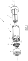
- FIG. 1 represents a synchronous electric motor, here of the brushless direct switching and direct current type, also known by the acronym BLDC, for “Brushless direct current” in English.
- the motor 1 comprises a stator 2 and a rotor 3, movable relative to the stator 2 around an axis of rotation X.
- the stator 2 comprises a hollow body of tubular shape, here in the shape of a cylinder whose axis of revolution coincides with the axis X.
- the rotor 3 is received inside the stator 2 being positioned coaxially with the axis X.
- An air gap separates the rotor 3 from the stator 2.
- the diameter of the hollow body is less than or equal to 10cm or, preferably, less than or equal to 5cm.
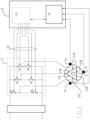
- the motor 1 is intended to be powered by a three-phase electric current, called supply current, generated by means of a control circuit, illustrated in figure 2 .
- this three-phase current is generated from a direct electrical voltage using a pulse width modulation method.
- the supply current is thus formed of three electrical currents out of phase with each other, each corresponding to a phase of the supply current, these phases being for example out of phase by 120° with respect to the 'other.
- the stator 2 comprises electromagnets intended to generate a rotating magnetic field to rotate the rotor 3.
- the electromagnets are arranged inside the stator 2, for example are distributed over a circumference of the internal face of the hollow body, around the X axis.
- Each electromagnet comprises a coil, or solenoid, formed by one or more windings, or turns, of an electrically conductive wire around an armature.
- the armatures are, for example, polar elements distributed over the internal circumference of the stator body and integral with the stator body.
- the conductive wire is for example made of enameled copper. Here it has a diameter less than or equal to 2mm, preferably less than or equal to 1mm, preferably less than or equal to 0.75mm.
- Each coil is intended to be electrically powered by a phase of the three-phase electrical supply current.
- the stator 2 comprises six coils, which are distributed over the internal circumference of the hollow body with an angle of 60° between two adjacent coils, this angle being measured relative to the axis
- the power supply therefore powers two separate coils.
- the coils corresponding to the same phase are arranged one opposite the other within the stator 2.
- the coils associated with the first phase of the supply current are denoted 21A and 21A'
- the coils associated with the second phase of the supply current are denoted 21B and 21B'
- the coils associated with the third phase of the supply current are denoted power supply are denoted 21C and 21C'.
- these coils are also generally designated by the generic reference 21.
- the coils 21 are illustrated so as to represent their electrical interconnection and not their spatial arrangement within the rotor 2.
- the control circuit of the motor 1 includes a switching module 11 which comprises a plurality of power switches denoted K1, K2, K3, K4, K5 and K6, which, depending on control signals 16 received, supply sequentially the coils 21 of the stator 2 so as to create a rotating magnetic field.
- the control sequences are generated as a function of the relative position of the rotor 3 relative to the coils 21 of the stator 2.
- the positioning of the switches K1 to K6 at a given instant constitutes a command which, via the phases of power supply to motor 1, determines its operation.
- the switching module 11 is controlled by a control device 12, which includes a module 13 for generating control signals.
- a control device 12 which includes a module 13 for generating control signals.
- Each of these modules comprises hardware and software means arranged and configured so that the control device implements the method of generating control signals to manage the operation of the engine as will be described below.
- the control signal generation module 13 recovers in particular, via a signal reception interface 15, information from magnetic field sensors 14, positioned fixedly relative to the stator 2.
- these sensors 14 are Hall effect sensors with binary output.
- these sensors 14 are positioned at 120° or 60° from each other inside the stator 2.
- the module 13 for generating control signals estimates the position without sensors, for example as described in the application EP3014758 .
- the rotor 3 has a rotor body which is provided with magnetic elements, not shown, such as permanent magnets, which are arranged on the periphery of the rotor body.
- magnetic elements not shown, such as permanent magnets, which are arranged on the periphery of the rotor body.
- the magnetic elements are surrounded by the stator 2 to interact with the rotating magnetic field created by the coils 21 of the stator 2.
- These magnetic elements are for example ferrite magnets.
- the rotor 3 also includes an output shaft 31, which drives a reduction gear, and through the gear reducer, an output shaft of an electromechanical actuator.
- the latter is configured to rotate a mechanical load when the rotor 3 is rotated by the rotating magnetic field.
- the mechanical load is a roller shutter, a blind or a screen.
- the motor 1 is thus intended to be used in a controllable electromechanical actuator.
- the stator 2 comprises a first flange 22 disposed on a first end of the hollow tubular body, in particular resting on its pack of sheets forming the hollow body of the stator and a second flange 24 disposed at the opposite end of the hollow tubular body of the stator 2.
- a support part 23 is also attached to the stator on the side of the first flange 22. Thus, the support part 23 forms part of the stator 2.
- the motor 1 also includes end bowls 26 and 27, or covers, which are fixed to the opposite ends of the hollow tubular body and which cover the flanges, respectively, 22 and 24 so as to close the rotor-stator assembly screw- from the outside and thus to protect the coils 21 of the stator 2.
- the bowl 26 here comprises access orifices to the stator, in particular electrical connection orifices, for example for supplying the coils of the stator 2 from the control circuit.
- the bowls 26 and 27 also include a central orifice, concentric with the axis X, to allow the passage of the rotor body shaft.
- the bowls 26 and 27 are here made of metallic material. They may include a cylindrical recess for receiving a bearing or a bearing in which the end of the rotor body passing through the bowl 26 or 27 is held.
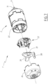
- THE figures 3 to 5 represent in more detail the flange 22 and the support part 23.
- the support part 23 is fixed to the flange 22 in a manner which will be explained later.
- the coils 21 are here connected to the three phases of the supply current in a triangle arrangement, as shown in the figure 2 .
- the coils 21 associated with the same electrical phase of the supply current are connected in series with one another. They thus form a pair of coils. Each pair of coils thus formed is connected, at each end, to one end of another pair of coils associated with a different electrical phase of the supply current.
- the coils 21A and 21A' are connected in series and are intended to be powered by the first phase of the supply current.
- the coils 21A and 21A' are formed by successive winding of the same conductive wire around two distinct armatures arranged on the stator 2.
- the two coils 21A and 21A' are thus connected in series by means of an intermediate portion of the conductive wire , not illustrated, which extends here at the opposite end of the body of the stator 2.
- the flange 24 comprises means for guiding and holding this portion of intermediate wire.
- the wire portions 211A and 211A' protrude out of the hollow body of the stator on the side of its first end.
- the other coils 21 are connected in a similar manner.
- the coils 21B and 21B' are made from a second conductive wire and the coils 21C and 21C' are made from a third conductive wire.
- 211B and 211B' the end portions of conductive wire associated with the coils 21B and 21B'
- 211C and 211C' the end portions of conductive wire associated with the coils 21C and 21C'.
- the portions 211A and 211B are connected together at a first common connection point
- the portions 211C and 211A' are connected together at a second point of connection.
- common connection and the portions 211B' and 211C' are connected together to a third common connection point.
- the first, second and third common connection points are connected, respectively, to the first phase, the second phase and the third phase of the supply current.
- the stator 2 comprises only three coils 21, each associated with one of the three electrical phases.
- the portions 211A and 211A' correspond to the opposite ends of the same coil 21A, the coil 21A' being omitted.
- the flange 22 is mounted integrally with the first end of the body of the stator 2.
- the flange 22 comprises a rigid body 221, secured to the stator 2.
- the flange 22 is made of electrically insulating material, for example plastic, such as polybutylene terephthalate or polyamide 66.
- the flange 22 also includes holding zones 222 which ensure the holding of the wire end portions to facilitate their connection.
- Each holding zone 222 is associated with a wire end portion.
- the holding zones 222 are here six in number, that is to say as many as the wire end portions 211A, 211A', 211B, 211B', 211C and 211C' present at the level of the flange 22.
- Each holding zone 222 includes one or more edges 223 in the form of a groove or groove on the outside of the flange, which receive a corresponding end portion of conductive wire. These edges 223 each extend over part of the periphery of the flange 22. Thus, the portion of wire received in a flange 223 extends along part of the periphery of the flange 22.
- the flange 22 has a cylindrical shape with a circular base.
- the grooves 223 therefore each describe a portion of an arc of a circle in a geometric plane perpendicular to the axis X.
- the width of the grooves 223 is chosen as a function of the diameter of the conductive wire. It is identical here for all the grooves 223 of the flange 22.
- the zones 222 also include one or more recesses 224 provided in the flange.
- a recess 224 is provided between two grooves 223.
- the Corresponding wire end portion associated with this zone 222 is here received in the two grooves 223 and extends above the recess 224.
- the flange 22 also includes fixing members 226 intended to maintain the ends, or end zones, of the end portions 211A, 211A', 211B, 211B', 211C and 211C' of the conductive wires received here in the zones 222.
- Each fixing member 226 comprises a clamp comprising two branches tightened against each other by elasticity. For example, these branches are made in one piece with the rest of the flange 22.
- end portions 211A, 211A', 211B, 211B', 211C and 211C' are here pinched and held in these fixing members 226, between the two branches of the clamps and extend perpendicular to the periphery of the flange 22.
- the same fixing member 226 fixes two distinct wire end portions belonging to different phases.
- the support part 23 comprises a body 231 and electrical connectors 233, 233' and 233" carried by this body 231.
- the body 231 is of generally circular and planar shape and is pierced with a central recess 232 to allow the passage of the rotor 3 when the motor 1 is in an assembled configuration.
- the support part 23 also comprises envelopes 234, each of which surrounds at least partly one of the connectors 233, 233' and 233" and which are here formed in one piece with the main part 231.
- each envelope 234 is overmolded over part of the connector 233, 233' and 233" with which it is associated.
- the support piece 23 has two opposite faces, here an upper face and a lower face. Connectors 233, 233' and 233" are supported by the upper face.
- the body 231 and the envelopes 234 are made of plastic material by thermoforming.
- plastic material for example, polybutylene terephthalate or polyamide 66 is used.
- the connectors 233, 233' and 233" are arranged around the periphery of the body 231, being separated two by two by an angle of 120°, measured in a geometric plane perpendicular to the axis X2.
- the connectors 233, 233' and 233" are identical.
- only connector 223 is described in detail in the following.
- the elements of connectors 233' and 233" which are similar to the elements of connector 233 bear the same numerical reference, to which is added, respectively, the symbol "'" and the symbol "”.
- the connector 233 comprises a straight power supply terminal 2331 and two curved blades 2332 and 2333 which are arranged on either side of the terminal 2331 and which are electrically connected to the terminal 2331, here by a connection portion 2334.
- the connector 233 is here made in one piece.
- the connector 233 is made of metallic material, preferably of a copper-zinc alloy, such as CuZn33 R480, pre-hot tinned with a layer of tin with a thickness of between 1 ⁇ m and 3 ⁇ m.
- a copper-zinc alloy such as CuZn33 R480
- each curved blade 2332, 2333 has an inverted U shape, a first branch of which is joined to the connection portion 2334.
- a second branch of the inverted U shape is extends over the peripheral edge of the flange 22 and its distal end is folded and is received at a recess 224.
- the lug 2331 extends parallel to the axis
- Each connector 233, 233' and 233" connects two by two coils associated with distinct phases by means of curved blades 2332 and 2333.
- Each lug 2331 is intended to be connected to an electrical phase of the supply current, here conveyed by a dedicated electrical cable.
- Each connector 233, 233' and 233" thus corresponds to a common connection point of the triangle assembly of the coils 21.
- the connectors 233, 233' and 233" are placed on the support part 23 such that the connection portion 2335 faces the inside of the flange 22.
- the flange 22 and the support part 23 then form a system for electrically connecting the coils 21 in order to ensure their current supply.
- the support part 23 is fixed to the flange 22, without degree of freedom.
- the connectors 233, 233' and 233", and in particular the curved blades 2332, 2333 are arranged differently, for example by being open towards the center of the support part 23.
- the ends 211A, 211A', 211B, 211B', 211C and 211C' of coil wires do not extend around the flange, but run towards the inside of the rotor, in particular through a specific operation of the winding device described below. In this way, on the one hand, we prevent the ends of the curved blades 2332, 2333 from projecting outside of the flange 22, which could hinder the positioning of the bowl 26. On the other hand, we avoid the tension of the wires before their welding at the level of the curved blades 2332, 2333.
- the support part 23 is an insert separate from the flange 22 and which is fixed to the flange 22 without degree of freedom.
- the support part 23 and the flange 22 comprise fixing members of complementary shape.
- the flange 22 contains lugs 227 and the support part 23 comprises housings 235, here provided at the base of the envelopes 234.
- Each housing has a shape complementary to that of the fixing studs 227.
- the part of support 23 abuts on the end of the flange facing towards the bowl 26.
- the motor 1 comprises a printed circuit 25, including a rigid substrate on which electrically conductive tracks and electronic components are provided. These components are for example magnetic field sensors which make it possible to measure the rotating magnetic field created by the coils 21.
- the printed circuit 25 is fixed on the lower face of the body 231 of the support part 23, for example by ultrasonic welding or by hot welding.
- the lower face includes elements for attaching the printed circuit 25.
- the printed circuit 25 if it is necessary for the operation of the motor 1, is held axially by the lower face of the support part.
- the diameter of the support piece-printed circuit assembly is not increased beyond the maximum diameter of one or the other of the support piece 23 or the printed circuit 25, as would be the case with side hanging elements.
- the body 231 of the support part 23 comprises plastic pins intended to be inserted into corresponding orifices formed on the circuit 25, then crushed hot to hold the printed circuit 25 and the support part 23 one to the other. the other.
- the circuit 25 here comprises a connection box 251, arranged on an upper face of the substrate facing the support piece 23 and being connected to the components of the printed circuit 25 via the tracks of the circuit 25.
- This connection box 251 allows connecting the components to the control circuit of the motor 1.
- the support part 23 includes a cutout on its circular edge allowing the passage of this connection box 251 when the printed circuit 25 is attached to the support part 23.
- the bowl 26 advantageously includes an orifice of complementary shape to that of the housing 251 allowing access to it from outside the motor 1.
- An advantage of motor 1 is therefore that the functions linked to the connection are carried out on a dedicated support part 23 and not directly on the stator 2 or via circuit 25.
- zones 222 make it possible to extend and maintain the wire end portions around the periphery of the flange, which facilitates the construction of the motor 1 and also makes it possible to arrange the connectors on the periphery of the stator 2, at the deviation from the X axis.
- circuit 25 is intended to be fixed on the intermediate part and not directly on the stator and the connection of the coils is carried out independently of this circuit 25, then the absence of circuit 25 does not penalize the construction of the motor 1.
- stator 2 is supplied with the flange 22 secured to one of the ends of the stator.
- the coils 21 are formed by winding conductive wires around the armatures of the stator 2.
- each pair of coils associated with the same electrical phase is formed using the same wire.
- three wires are used to form the coils 21.
- the coils 21A and 21A' are formed one after the other by winding a first wire around two distinct armatures. Once the winding is completed, the opposite end parts 211A and 211A' of this conductive wire are brought and are located at the first end of the stator 22. Analogously, the coils 21B and 21B' are produced by winding of a second conductive wire, and the coils 21C and 21C' are made by winding a third conductive wire.
- the winding is here carried out by means of an automatic needle winding device, preferably simultaneously for the three conductive wires.
- the needle winding apparatus comprises a needle support which is provided with a movable winding head mounted at the end of a shaft capable of being moved back and forth in the stator 2 along the X axis.
- This winding head has several winding needles which are arranged to slide inside the winding head.
- Each winding needle is associated with a conductive thread to be wound, this thread being unwound from a corresponding reserve.
- each winding needle comprises an axial channel through which the conductive wire to be wound passes.
- the needle support When the needle support makes a rectilinear back and forth movement along the axis X inside the stator 2, it repeatedly reaches so-called dead center positions, located at the opposite ends of its rectilinear trajectory. At each of these dead center positions, the needle support rotates in a predefined direction with a chosen angle which corresponds to the number of turns of the winding to be produced on the armature of the coils. The conductive thread thus follows the path that the winding needle takes in its movement. The coil windings are thus formed gradually.
- the needle winding device is for example set in motion by means of controllable actuators controlled by an electronic control unit which executes a predefined manufacturing program.
- the coils 21 are manufactured and the corresponding wire end portions 211A, 211A', 211B, 211B', 211C, 211C' extend at the level of the first end of the stator 2 , for example being held in position thanks to the needles of the winding device or being attached to the flange 22, being advantageously fixed thanks to the fixing members 226.
- each end portion 211A, 211A', 211B, 211B', 211C, 211C' is moved along the outside of the flange then inserted between the branches of the clamp of the fixing members, the end zones ends protruding radially relative to the periphery of the flange 22. This movement is ensured here thanks to specific programming of the winding device.
- the support part 23 is secured to the flange 22.
- the support part 23 is first positioned above the flange 22 such that the housings 235 are aligned with the studs 227 and possibly that the blades 2332 and 2333 are aligned with the corresponding recesses 224.
- the printed circuit 25 is previously fixed on the support part 23, by securing the substrate of the circuit 25 to the lower face of the body 231, as explained previously.
- the support part 23 is then moved by translation along the axis the curved blades of the connectors 2332 and 2333, 2332' and 2333', 2332" and 2333" intercept the corresponding end portions 211A, 211A', 211B, 211B', 211C, 211C' and exert support on the latter for the bring towards the respective zones 222 in the case where these ends are held on the flange.
- the connectors 233 are electrically connected to the coils 21 by welding.
- the curved blades 2332, 2333 are folded to grip the corresponding portion of wire, by exerting a force to deform these blades so as to grip the corresponding portion of wire. The welding is then carried out once the blade is folded.
- the portions of conductive wire which protrude from the clamps 236 perpendicular to the circumference of the flange 22 are then cut.
- This method has the advantage that the wire portions are held in place on the flange thanks to the grooves 223, allowing easier connection of the support part 23.
- the wire ends are brought to the level of these curved blades after the support piece is placed on the flange, by corresponding programming of the winding device.
- the assembly of the motor 1 is finalized, in particular by inserting the rotor 3 into the body of the stator 2 and by fixing the bowls 26 and 27 on the ends of the stator 2.
- THE figures 7 And 8 represent a motor 1' according to a second embodiment of the invention.
- the additional part 28 comprises at least one radial arm, here three coplanar radial arms, extended perpendicular to the axis crossed by a part of the rotor 3.
- the part 28 also includes a protrusion 281 at the end of at least one radial arm, intended to support a remote electrical connector connected to the circuit 25' in replacement of the connector 251.
- the protrusion 281 extends parallel to the axis corresponding connection formed in the bowl 26.
- Conductive tracks are provided and extend inside the protrusion 281 and the radial arm supporting it. These conductive tracks are connected to circuit 25' and to sensors 14 mounted on the PCB.
- the support part 23' comprises a body 231 provided with a central orifice 232' widened relative to the orifice 232 to allow the passage of at least part of the printed circuit 25'.
- the central orifice 232' has a shape complementary to the shape of the printed circuit 25', more precisely to the shape of a rigid substrate of the printed circuit 25'. It is thus understood that, in an assembled configuration of the stator 2', the printed circuit 25' is partially, preferably completely, received inside the orifice 232'. Retaining walls 291 of the circuit 25' are provided at the base of the support part 23', on the side opposite to that of the insertion of the circuit 25' into the orifice 232'. Thus, in a mounted configuration of the additional part 28 on the support piece 23', the circuit 25' is retained axially between the additional piece 28 and the support piece 23'.
- the support part 23' also comprises at least one distance finger 292 relative to the rotor 3.
- This distance finger(s) project axially relative to the upper face of the support part 23' supporting the connectors 233, 233', 233".
- the end 293 of these distancing fingers 292 is in contact with the bearing received in the bowl 26.
- the sensors positioned on the circuit 25' are at a distance from the rolling predefined by the height of the guide fingers.
- the curved blades 2332 and 2333 of each of the connectors 233 of the support part 23' are here turned towards the center of the support 23.
- the flange 22' is modified accordingly.
- the flange 22' comprises, for each of the connectors 233, a fixing tab 227' and recesses 224 associated with the curved blades 2332 and 2333.
- This arrangement of the curved blades 2332 and 2333 can nevertheless be implemented independently of the part 28 and the shape described above of the support part 23'.
- the role of the flange 22' is similar to the role of the flange 22 previously described.
- the flange 22' is mounted integrally on one end of the stator 2' while resting on a pack of sheets forming a hollow body of the stator 2'.
- the flange 22' comprises on the one hand a circular ring, which is placed on the external periphery of the sheets forming the stator.
- the flange also includes a plurality of caps 294, held to the flange ring by bridges extending from the flange ring towards the interior thereof.
- the caps 294 have a thickness substantially equal to that of the stator sheets and a width equivalent to the pole elements of the stator.
- the caps 294 thus form end portions or extensions of the pole elements of the stator.
- the stator coils are each formed by winding an electrically conductive wire around a pole element and caps on either side of this pole element.
- the support piece 23' is held in support on the caps 294.
- the support piece can only be mounted indexed in rotation relative to the flange. It is then held by assembly (simple stacking of parts) between the flange and the bearing inserted in the bowl 26, during assembly of the bowl 26 on the flange and the stator.
- This second embodiment makes it possible in particular to offer better axial positioning of the sensors mounted on the printed circuit 25' in relation to the rotor magnets, by reducing the side chain and by simplifying the assembly process of the motor 1'.
- the bearing being attached to a predefined distance on a shaft of the rotor, the sensors positioned on the circuit 25' being at a distance from the bearing predefined by the height of the guide fingers, are therefore at a predefined distance from the rotor, guaranteed by the positioning of the bearing on the rotor axis.
Landscapes
- Engineering & Computer Science (AREA)
- Power Engineering (AREA)
- Manufacture Of Motors, Generators (AREA)
- Windings For Motors And Generators (AREA)
- Insulation, Fastening Of Motor, Generator Windings (AREA)
- Motor Or Generator Frames (AREA)
Claims (9)
- Synchroner Elektromotor (1; 1'), umfassend einen rohrförmigen Stator (2; 2') und einen Rotor (3), der im Inneren des Stators (2; 2') um eine zum Stator (2; 2') koaxiale Drehachse (X) drehbeweglich ist; der Stator (2; 2') umfassend zwei Enden und beinhaltend Spulen (21A, 21A', 21B, 21B', 21C, 21 C'), die jeweils durch Wickeln eines elektrisch leitenden Drahts gebildet sind, wobei der Stator (2; 2') Folgendes umfasst:- einen Flansch (22; 22'), der fest an einem der Enden des Stators (2; 2') montiert ist, indem er sich auf einem Blechpaket abstützt, das einen Hohlkörper des Stators (2; 2') bildet;- ein elektrisch isolierendes Trägerteil (23), das an dem Flansch befestigt und mit elektrischen Verbindern (233, 233', 233") versehen ist, die jeweils einen Stromversorgungsanschluss (2331, 2331', 2331") und zwei gebogene Lamellen (2332, 2333, 2332', 2333', 2332", 2333") in elektrischer Verbindung mit dem entsprechenden Stromversorgungsanschluss umfassen, wobei die gebogenen Lamellen von jedem Verbindungselements jeweils elektrisch mit einem Drahtendabschnitt einer Spule verbunden sind, wobei jeder Verbinder (233, 233', 233") einen gemeinsamen Verbindungspunkt zwischen zwei Spulen (21A, 21A', 21B, 21B', 21C, 21 C') bildet, die mit unterschiedlichen elektrischen Versorgungsphasen des Motors (1, 1') verbunden sind,dadurch gekennzeichnet, dass der Elektromotor ferner eine Leiterplatte (25; 25') umfasst, wovon ein starres Substrat zwischen das Trägerteil (23; 23') und den Flansch (22; 22') eingefügt ist.
- Elektromotor nach Anspruch 1, dadurch gekennzeichnet, dass die Leiterplatte (25') zumindest teilweise innerhalb einer mittleren Öffnung (232') des Trägerteils (23') aufgenommen ist.
- Elektromotor nach Anspruch 1 oder 2, dadurch gekennzeichnet, dass er ein zusätzliches Teil (28) zum Tragen der Leiterplatte (25') umfasst, das zwischen das Trägerteil (23') und eine Endschale (26) eingefügt ist, wobei das zusätzliche Teil mit einer Ausstülpung (281) versehen ist, die bereitgestellt ist, um einen abgesetzten elektrischen Verbinder zu tragen, der mit der Leiterplatte (25') verbunden ist.
- Elektromotor nach einem der vorherigen Ansprüche, dadurch gekennzeichnet, dass die Spulen (21A, 21A', 21B, 21B', 21C, 21 C') in einer Dreiecksschaltung elektrisch miteinander verbunden sind.
- Elektromotor nach einem der vorherigen Ansprüche, dadurch gekennzeichnet, dass die Verbinder (233, 233', 233") in einem Winkel von 120° um den Umfang des Trägerteils (23; 23') voneinander beabstandet angeordnet sind.
- Elektromotor nach einem der vorherigen Ansprüche, dadurch gekennzeichnet, dass das Trägerteil (23; 23') durch Einrasten an dem Flansch (22; 22') befestigt ist, wobei der Flansch und das Trägerteil zu diesem Zweck Befestigungselemente (227, 235; 227') mit komplementären Formen umfassen.
- Elektromotor nach einem der vorherigen Ansprüche, dadurch gekennzeichnet, dass das Trägerteil (23; 23') an einem Endrand des Flanschs (22; 22') anliegt.
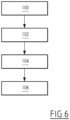
- Verfahren zur Herstellung eines synchronen Elektromotors (1) nach Anspruch 1, dieser Motor umfassend einen rohrförmigen Stator (2; 2') und einen Rotor (3), der im Inneren des Stators (2; 2') um eine zum Stator (2; 2') koaxiale Drehachse (X) drehbar ist, wobei dieses Verfahren die folgenden Schritte umfasst:a) Bereitstellen eines Stators (2; 2'), der mit einem Flansch (22; 22') versehen ist, der fest an einem der Enden des Stators (2; 2') montiert ist, indem er sich auf einem Blechpaket abstützt, das einen Hohlkörper des Stators (2; 2') bildet;b) Wickeln (100) elektrisch leitender Drähte, um Spulen (21A, 21A', 21B, 21B', 21C, 21 C') innerhalb des Stators (2; 2') zu bilden;c) Befestigen (102; 104) eines elektrisch isolierenden Trägerteils (23; 23') an dem Flansch (22; 22'), wobei dieses Trägerteil (23; 23') mit elektrischen Verbindern (233, 233', 233") versehen ist, die jeweils einen Stromversorgungskabelschuh (2331, 2331', 2331") und zwei gebogene Lamellen (2332, 2333, 2332', 2333', 2332", 2333") in elektrischer Verbindung mit dem Stromversorgungskabelschuh beinhalten, wobei jede gebogene Lamelle gegenüber einem Endabschnitt (211A, 211A', 211B, 211B', 211C, 211C') eines Drahts einer Spule positioniert ist, um diesen Drahtabschnitt zu umschließen;d) elektrische Verbindung (106) von jeder gebogenen Lamelle (2332, 2333, 2332', 2333', 2332", 2333") mit dem eingeklemmten Endabschnitt (211A, 211A', 211B, 211B', 211C, 211C'), wobei jeder Verbinder (233, 233', 233") einen gemeinsamen Verbindungspunkt zwischen zwei Spulen (21A, 21A', 21B, 21B', 21C, 21 C') bildet, die mit unterschiedlichen elektrischen Versorgungsphasen des Motors (1, 1') assoziiert sind,dadurch gekennzeichnet, dass das Verfahren einen Schritt eines Hinzufügens einer Leiterplatte (25; 25') vor dem Schritt eines Befestigens des Trägerteils (23) an dem Flansch (22) umfasst, wobei ein starres Substrat der Leiterplatte (25; 25') zwischen das Trägerteil (23; 23') und den Flansch (22; 22') eingefügt wird.
- Herstellungsverfahren nach Anspruch 8, dadurch gekennzeichnet, dass es einen Schritt eines Befestigens einer Schale (26) an dem Stator umfasst, wobei die Stromversorgungskabelschuhe durch den Boden der Schale (26) hervorstehen, wenn diese an dem Stator montiert ist.
Applications Claiming Priority (2)
| Application Number | Priority Date | Filing Date | Title |
|---|---|---|---|
| FR1753108A FR3065125B1 (fr) | 2017-04-10 | 2017-04-10 | Moteur electrique synchrone et procede d'assemblage de ce moteur electrique |
| PCT/EP2018/059112 WO2018189150A1 (fr) | 2017-04-10 | 2018-04-10 | Moteur électrique synchrone et procédé d'assemblage de ce moteur électrique |
Publications (2)
| Publication Number | Publication Date |
|---|---|
| EP3610562A1 EP3610562A1 (de) | 2020-02-19 |
| EP3610562B1 true EP3610562B1 (de) | 2023-12-06 |
Family
ID=59649808
Family Applications (1)
| Application Number | Title | Priority Date | Filing Date |
|---|---|---|---|
| EP18715731.8A Active EP3610562B1 (de) | 2017-04-10 | 2018-04-10 | Elektrischer synchronmotor und verfahren zur montage des besagten elektrischen motors |
Country Status (4)
| Country | Link |
|---|---|
| EP (1) | EP3610562B1 (de) |
| CN (1) | CN110622397B (de) |
| FR (1) | FR3065125B1 (de) |
| WO (1) | WO2018189150A1 (de) |
Families Citing this family (2)
| Publication number | Priority date | Publication date | Assignee | Title |
|---|---|---|---|---|
| FR3099318B1 (fr) * | 2019-07-25 | 2021-08-27 | Somfy Activites Sa | Moteur électrique, actionneur électromécanique comprenant un tel moteur électrique et installation comprenant un tel actionneur |
| CN112072854A (zh) * | 2020-09-15 | 2020-12-11 | 东莞市徕芬电子科技有限公司 | 一种电机 |
Family Cites Families (9)
| Publication number | Priority date | Publication date | Assignee | Title |
|---|---|---|---|---|
| JP4783012B2 (ja) * | 2004-12-28 | 2011-09-28 | 日立オートモティブシステムズ株式会社 | 電動パワーステアリング用モータ及びその製造方法 |
| EP2330720B1 (de) * | 2009-12-04 | 2012-08-15 | ebm-papst Mulfingen GmbH & Co. KG | Elektrischer Außenläufermotor mit einem Gehäuse und einem Formteil zum Führen elektrischer Leiter, die mit einem Strangpressverfahren hergestellt sind |
| CN102163895B (zh) * | 2011-03-22 | 2013-03-06 | 华北电力大学 | 一种用于研究铁芯损耗影响因素的交流电动机 |
| FR3007911B1 (fr) | 2013-06-27 | 2015-06-26 | Somfy Sas | Dispositif de controle d’un moteur |
| DE102013113363A1 (de) * | 2013-12-03 | 2015-06-03 | Pierburg Gmbh | Stator für einen elektronisch kommutierten Gleichstrommotor |
| CN104104201B (zh) * | 2014-06-27 | 2016-12-07 | 中山市恒和电子科技有限公司 | 一种三相无刷直流风扇电机 |
| JP6589336B2 (ja) * | 2015-03-30 | 2019-10-16 | 日本電産株式会社 | モータおよび車載装置 |
| FR3039725B1 (fr) * | 2015-07-30 | 2017-08-25 | Bubendorff | Machine tournante synchrone autopilotee a dispositif de freinage. |
| CN106208578B (zh) * | 2016-08-04 | 2018-09-04 | 日本电产凯宇汽车电器(江苏)有限公司 | 一种永磁同步电动机 |
-
2017
- 2017-04-10 FR FR1753108A patent/FR3065125B1/fr active Active
-
2018
- 2018-04-10 WO PCT/EP2018/059112 patent/WO2018189150A1/fr not_active Ceased
- 2018-04-10 CN CN201880030490.6A patent/CN110622397B/zh active Active
- 2018-04-10 EP EP18715731.8A patent/EP3610562B1/de active Active
Also Published As
| Publication number | Publication date |
|---|---|
| EP3610562A1 (de) | 2020-02-19 |
| WO2018189150A1 (fr) | 2018-10-18 |
| FR3065125A1 (fr) | 2018-10-12 |
| FR3065125B1 (fr) | 2019-07-05 |
| CN110622397B (zh) | 2022-10-14 |
| CN110622397A (zh) | 2019-12-27 |
Similar Documents
| Publication | Publication Date | Title |
|---|---|---|
| FR2804255A1 (fr) | Corps de bobinage destine a recevoir un bobinage pour un convertisseur electro-magneto-mecanique, et convertisseur electro-magneto-mecanique | |
| EP1251629A1 (de) | Elektrische Maschine mit mindestens einem Magnetfelddetektor | |
| EP2624415A1 (de) | Elektrischer Motor mit einer haken aufweisenden Verbindunsplatte | |
| EP1251623A1 (de) | Stator für elektrische Maschine mit einzeln herauslösbaren Spulen | |
| FR2901645B1 (fr) | Procede de formation et dispositif de formation de partie d'extremite d'enroulement dynamo-electrique | |
| WO2008074954A1 (fr) | Machine electrique tournante, en particulier pour un demarreur de vehicule automobile | |
| FR3065125B1 (fr) | Moteur electrique synchrone et procede d'assemblage de ce moteur electrique | |
| WO2020025405A1 (fr) | Machine électrique tournante | |
| FR2920259A1 (fr) | Machine electrique tournante, en particulier pour un demarreur automobile | |
| CH699082A1 (fr) | Moteur électrique avec connecteur. | |
| EP3491717B1 (de) | Elektrische drehmaschine mit einem verbinder mit radial gestapelten kopplungsspuren | |
| EP0248798A1 (de) | Elektrischer synchronmotor mit dauermagnetischem läufer und herstellungsverfahren dieses motors. | |
| EP4078779A1 (de) | Stator mit einem verbinder | |
| FR2719324A1 (fr) | Appareil de traitement du linge utilisant un tambour à entraînement direct électromotorisé. | |
| EP0042884A1 (de) | Magnetmotor mit elektromagnetischer Erregung | |
| EP4078780A1 (de) | Stator mit einem verbinder | |
| EP1925011B1 (de) | Wärmekraftmaschinenanlasserschalter mit verbesserten elektrischen verbindungsmitteln der wicklung | |
| FR2497017A1 (fr) | Machine electrique rotative et notamment un micromoteur | |
| EP3491715B1 (de) | Mit einer wicklung mit verbesserter konfiguration ausgestattete, rotierende elektrische maschine | |
| FR2910192A1 (fr) | Machine electrique tournante, en particulier pour un demarreur de vehicule automobile | |
| WO2019016242A1 (fr) | Machine electrique tournante comportant un dispositif de maintien de l'extremite d'un fil electrique participant au bobinage | |
| FR3128329A1 (fr) | Rotor bobiné pour moteur électrique agencé pour faciliter son assemblage | |
| FR3148503A1 (fr) | Système d’assemblage d’un bobinage de stator | |
| FR3152677A1 (fr) | Machine électrique tournante | |
| EP4165759A1 (de) | Statoranordnung für einen elektronisch kommutierten elektromotor |
Legal Events
| Date | Code | Title | Description |
|---|---|---|---|
| STAA | Information on the status of an ep patent application or granted ep patent |
Free format text: STATUS: UNKNOWN |
|
| STAA | Information on the status of an ep patent application or granted ep patent |
Free format text: STATUS: THE INTERNATIONAL PUBLICATION HAS BEEN MADE |
|
| PUAI | Public reference made under article 153(3) epc to a published international application that has entered the european phase |
Free format text: ORIGINAL CODE: 0009012 |
|
| STAA | Information on the status of an ep patent application or granted ep patent |
Free format text: STATUS: REQUEST FOR EXAMINATION WAS MADE |
|
| 17P | Request for examination filed |
Effective date: 20191003 |
|
| AK | Designated contracting states |
Kind code of ref document: A1 Designated state(s): AL AT BE BG CH CY CZ DE DK EE ES FI FR GB GR HR HU IE IS IT LI LT LU LV MC MK MT NL NO PL PT RO RS SE SI SK SM TR |
|
| AX | Request for extension of the european patent |
Extension state: BA ME |
|
| DAV | Request for validation of the european patent (deleted) | ||
| DAX | Request for extension of the european patent (deleted) | ||
| STAA | Information on the status of an ep patent application or granted ep patent |
Free format text: STATUS: EXAMINATION IS IN PROGRESS |
|
| 17Q | First examination report despatched |
Effective date: 20210126 |
|
| GRAP | Despatch of communication of intention to grant a patent |
Free format text: ORIGINAL CODE: EPIDOSNIGR1 |
|
| STAA | Information on the status of an ep patent application or granted ep patent |
Free format text: STATUS: GRANT OF PATENT IS INTENDED |
|
| INTG | Intention to grant announced |
Effective date: 20230726 |
|
| GRAS | Grant fee paid |
Free format text: ORIGINAL CODE: EPIDOSNIGR3 |
|
| GRAA | (expected) grant |
Free format text: ORIGINAL CODE: 0009210 |
|
| STAA | Information on the status of an ep patent application or granted ep patent |
Free format text: STATUS: THE PATENT HAS BEEN GRANTED |
|
| AK | Designated contracting states |
Kind code of ref document: B1 Designated state(s): AL AT BE BG CH CY CZ DE DK EE ES FI FR GB GR HR HU IE IS IT LI LT LU LV MC MK MT NL NO PL PT RO RS SE SI SK SM TR |
|
| REG | Reference to a national code |
Ref country code: GB Ref legal event code: FG4D Free format text: NOT ENGLISH |
|
| REG | Reference to a national code |
Ref country code: CH Ref legal event code: EP |
|
| REG | Reference to a national code |
Ref country code: DE Ref legal event code: R096 Ref document number: 602018062170 Country of ref document: DE |
|
| REG | Reference to a national code |
Ref country code: IE Ref legal event code: FG4D Free format text: LANGUAGE OF EP DOCUMENT: FRENCH |
|
| REG | Reference to a national code |
Ref country code: LT Ref legal event code: MG9D |
|
| PG25 | Lapsed in a contracting state [announced via postgrant information from national office to epo] |
Ref country code: GR Free format text: LAPSE BECAUSE OF FAILURE TO SUBMIT A TRANSLATION OF THE DESCRIPTION OR TO PAY THE FEE WITHIN THE PRESCRIBED TIME-LIMIT Effective date: 20240307 |
|
| REG | Reference to a national code |
Ref country code: NL Ref legal event code: MP Effective date: 20231206 |
|
| PG25 | Lapsed in a contracting state [announced via postgrant information from national office to epo] |
Ref country code: LT Free format text: LAPSE BECAUSE OF FAILURE TO SUBMIT A TRANSLATION OF THE DESCRIPTION OR TO PAY THE FEE WITHIN THE PRESCRIBED TIME-LIMIT Effective date: 20231206 |
|
| PG25 | Lapsed in a contracting state [announced via postgrant information from national office to epo] |
Ref country code: ES Free format text: LAPSE BECAUSE OF FAILURE TO SUBMIT A TRANSLATION OF THE DESCRIPTION OR TO PAY THE FEE WITHIN THE PRESCRIBED TIME-LIMIT Effective date: 20231206 |
|
| PG25 | Lapsed in a contracting state [announced via postgrant information from national office to epo] |
Ref country code: LT Free format text: LAPSE BECAUSE OF FAILURE TO SUBMIT A TRANSLATION OF THE DESCRIPTION OR TO PAY THE FEE WITHIN THE PRESCRIBED TIME-LIMIT Effective date: 20231206 Ref country code: GR Free format text: LAPSE BECAUSE OF FAILURE TO SUBMIT A TRANSLATION OF THE DESCRIPTION OR TO PAY THE FEE WITHIN THE PRESCRIBED TIME-LIMIT Effective date: 20240307 Ref country code: ES Free format text: LAPSE BECAUSE OF FAILURE TO SUBMIT A TRANSLATION OF THE DESCRIPTION OR TO PAY THE FEE WITHIN THE PRESCRIBED TIME-LIMIT Effective date: 20231206 Ref country code: BG Free format text: LAPSE BECAUSE OF FAILURE TO SUBMIT A TRANSLATION OF THE DESCRIPTION OR TO PAY THE FEE WITHIN THE PRESCRIBED TIME-LIMIT Effective date: 20240306 |
|
| REG | Reference to a national code |
Ref country code: AT Ref legal event code: MK05 Ref document number: 1639336 Country of ref document: AT Kind code of ref document: T Effective date: 20231206 |
|
| PG25 | Lapsed in a contracting state [announced via postgrant information from national office to epo] |
Ref country code: NL Free format text: LAPSE BECAUSE OF FAILURE TO SUBMIT A TRANSLATION OF THE DESCRIPTION OR TO PAY THE FEE WITHIN THE PRESCRIBED TIME-LIMIT Effective date: 20231206 |
|
| PG25 | Lapsed in a contracting state [announced via postgrant information from national office to epo] |
Ref country code: SE Free format text: LAPSE BECAUSE OF FAILURE TO SUBMIT A TRANSLATION OF THE DESCRIPTION OR TO PAY THE FEE WITHIN THE PRESCRIBED TIME-LIMIT Effective date: 20231206 Ref country code: RS Free format text: LAPSE BECAUSE OF FAILURE TO SUBMIT A TRANSLATION OF THE DESCRIPTION OR TO PAY THE FEE WITHIN THE PRESCRIBED TIME-LIMIT Effective date: 20231206 Ref country code: NO Free format text: LAPSE BECAUSE OF FAILURE TO SUBMIT A TRANSLATION OF THE DESCRIPTION OR TO PAY THE FEE WITHIN THE PRESCRIBED TIME-LIMIT Effective date: 20240306 Ref country code: NL Free format text: LAPSE BECAUSE OF FAILURE TO SUBMIT A TRANSLATION OF THE DESCRIPTION OR TO PAY THE FEE WITHIN THE PRESCRIBED TIME-LIMIT Effective date: 20231206 Ref country code: LV Free format text: LAPSE BECAUSE OF FAILURE TO SUBMIT A TRANSLATION OF THE DESCRIPTION OR TO PAY THE FEE WITHIN THE PRESCRIBED TIME-LIMIT Effective date: 20231206 Ref country code: HR Free format text: LAPSE BECAUSE OF FAILURE TO SUBMIT A TRANSLATION OF THE DESCRIPTION OR TO PAY THE FEE WITHIN THE PRESCRIBED TIME-LIMIT Effective date: 20231206 |
|
| PG25 | Lapsed in a contracting state [announced via postgrant information from national office to epo] |
Ref country code: IS Free format text: LAPSE BECAUSE OF FAILURE TO SUBMIT A TRANSLATION OF THE DESCRIPTION OR TO PAY THE FEE WITHIN THE PRESCRIBED TIME-LIMIT Effective date: 20240406 |
|
| PG25 | Lapsed in a contracting state [announced via postgrant information from national office to epo] |
Ref country code: CZ Free format text: LAPSE BECAUSE OF FAILURE TO SUBMIT A TRANSLATION OF THE DESCRIPTION OR TO PAY THE FEE WITHIN THE PRESCRIBED TIME-LIMIT Effective date: 20231206 Ref country code: AT Free format text: LAPSE BECAUSE OF FAILURE TO SUBMIT A TRANSLATION OF THE DESCRIPTION OR TO PAY THE FEE WITHIN THE PRESCRIBED TIME-LIMIT Effective date: 20231206 |
|
| PG25 | Lapsed in a contracting state [announced via postgrant information from national office to epo] |
Ref country code: SK Free format text: LAPSE BECAUSE OF FAILURE TO SUBMIT A TRANSLATION OF THE DESCRIPTION OR TO PAY THE FEE WITHIN THE PRESCRIBED TIME-LIMIT Effective date: 20231206 |
|
| PG25 | Lapsed in a contracting state [announced via postgrant information from national office to epo] |
Ref country code: SM Free format text: LAPSE BECAUSE OF FAILURE TO SUBMIT A TRANSLATION OF THE DESCRIPTION OR TO PAY THE FEE WITHIN THE PRESCRIBED TIME-LIMIT Effective date: 20231206 Ref country code: SK Free format text: LAPSE BECAUSE OF FAILURE TO SUBMIT A TRANSLATION OF THE DESCRIPTION OR TO PAY THE FEE WITHIN THE PRESCRIBED TIME-LIMIT Effective date: 20231206 Ref country code: RO Free format text: LAPSE BECAUSE OF FAILURE TO SUBMIT A TRANSLATION OF THE DESCRIPTION OR TO PAY THE FEE WITHIN THE PRESCRIBED TIME-LIMIT Effective date: 20231206 Ref country code: IT Free format text: LAPSE BECAUSE OF FAILURE TO SUBMIT A TRANSLATION OF THE DESCRIPTION OR TO PAY THE FEE WITHIN THE PRESCRIBED TIME-LIMIT Effective date: 20231206 Ref country code: IS Free format text: LAPSE BECAUSE OF FAILURE TO SUBMIT A TRANSLATION OF THE DESCRIPTION OR TO PAY THE FEE WITHIN THE PRESCRIBED TIME-LIMIT Effective date: 20240406 Ref country code: EE Free format text: LAPSE BECAUSE OF FAILURE TO SUBMIT A TRANSLATION OF THE DESCRIPTION OR TO PAY THE FEE WITHIN THE PRESCRIBED TIME-LIMIT Effective date: 20231206 Ref country code: CZ Free format text: LAPSE BECAUSE OF FAILURE TO SUBMIT A TRANSLATION OF THE DESCRIPTION OR TO PAY THE FEE WITHIN THE PRESCRIBED TIME-LIMIT Effective date: 20231206 Ref country code: AT Free format text: LAPSE BECAUSE OF FAILURE TO SUBMIT A TRANSLATION OF THE DESCRIPTION OR TO PAY THE FEE WITHIN THE PRESCRIBED TIME-LIMIT Effective date: 20231206 |
|
| PG25 | Lapsed in a contracting state [announced via postgrant information from national office to epo] |
Ref country code: PL Free format text: LAPSE BECAUSE OF FAILURE TO SUBMIT A TRANSLATION OF THE DESCRIPTION OR TO PAY THE FEE WITHIN THE PRESCRIBED TIME-LIMIT Effective date: 20231206 Ref country code: PT Free format text: LAPSE BECAUSE OF FAILURE TO SUBMIT A TRANSLATION OF THE DESCRIPTION OR TO PAY THE FEE WITHIN THE PRESCRIBED TIME-LIMIT Effective date: 20240408 |
|
| PG25 | Lapsed in a contracting state [announced via postgrant information from national office to epo] |
Ref country code: PT Free format text: LAPSE BECAUSE OF FAILURE TO SUBMIT A TRANSLATION OF THE DESCRIPTION OR TO PAY THE FEE WITHIN THE PRESCRIBED TIME-LIMIT Effective date: 20240408 Ref country code: PL Free format text: LAPSE BECAUSE OF FAILURE TO SUBMIT A TRANSLATION OF THE DESCRIPTION OR TO PAY THE FEE WITHIN THE PRESCRIBED TIME-LIMIT Effective date: 20231206 |
|
| REG | Reference to a national code |
Ref country code: DE Ref legal event code: R097 Ref document number: 602018062170 Country of ref document: DE |
|
| PG25 | Lapsed in a contracting state [announced via postgrant information from national office to epo] |
Ref country code: DK Free format text: LAPSE BECAUSE OF FAILURE TO SUBMIT A TRANSLATION OF THE DESCRIPTION OR TO PAY THE FEE WITHIN THE PRESCRIBED TIME-LIMIT Effective date: 20231206 |
|
| PLBE | No opposition filed within time limit |
Free format text: ORIGINAL CODE: 0009261 |
|
| STAA | Information on the status of an ep patent application or granted ep patent |
Free format text: STATUS: NO OPPOSITION FILED WITHIN TIME LIMIT |
|
| PG25 | Lapsed in a contracting state [announced via postgrant information from national office to epo] |
Ref country code: SI Free format text: LAPSE BECAUSE OF FAILURE TO SUBMIT A TRANSLATION OF THE DESCRIPTION OR TO PAY THE FEE WITHIN THE PRESCRIBED TIME-LIMIT Effective date: 20231206 |
|
| PG25 | Lapsed in a contracting state [announced via postgrant information from national office to epo] |
Ref country code: SI Free format text: LAPSE BECAUSE OF FAILURE TO SUBMIT A TRANSLATION OF THE DESCRIPTION OR TO PAY THE FEE WITHIN THE PRESCRIBED TIME-LIMIT Effective date: 20231206 Ref country code: DK Free format text: LAPSE BECAUSE OF FAILURE TO SUBMIT A TRANSLATION OF THE DESCRIPTION OR TO PAY THE FEE WITHIN THE PRESCRIBED TIME-LIMIT Effective date: 20231206 |
|
| REG | Reference to a national code |
Ref country code: DE Ref legal event code: R119 Ref document number: 602018062170 Country of ref document: DE |
|
| 26N | No opposition filed |
Effective date: 20240909 |
|
| PG25 | Lapsed in a contracting state [announced via postgrant information from national office to epo] |
Ref country code: MC Free format text: LAPSE BECAUSE OF FAILURE TO SUBMIT A TRANSLATION OF THE DESCRIPTION OR TO PAY THE FEE WITHIN THE PRESCRIBED TIME-LIMIT Effective date: 20231206 |
|
| PG25 | Lapsed in a contracting state [announced via postgrant information from national office to epo] |
Ref country code: MC Free format text: LAPSE BECAUSE OF FAILURE TO SUBMIT A TRANSLATION OF THE DESCRIPTION OR TO PAY THE FEE WITHIN THE PRESCRIBED TIME-LIMIT Effective date: 20231206 |
|
| REG | Reference to a national code |
Ref country code: CH Ref legal event code: PL |
|
| PG25 | Lapsed in a contracting state [announced via postgrant information from national office to epo] |
Ref country code: LU Free format text: LAPSE BECAUSE OF NON-PAYMENT OF DUE FEES Effective date: 20240410 |
|
| GBPC | Gb: european patent ceased through non-payment of renewal fee |
Effective date: 20240410 |
|
| REG | Reference to a national code |
Ref country code: BE Ref legal event code: MM Effective date: 20240430 |
|
| PG25 | Lapsed in a contracting state [announced via postgrant information from national office to epo] |
Ref country code: LU Free format text: LAPSE BECAUSE OF NON-PAYMENT OF DUE FEES Effective date: 20240410 |
|
| PG25 | Lapsed in a contracting state [announced via postgrant information from national office to epo] |
Ref country code: DE Free format text: LAPSE BECAUSE OF NON-PAYMENT OF DUE FEES Effective date: 20241105 |
|
| PG25 | Lapsed in a contracting state [announced via postgrant information from national office to epo] |
Ref country code: BE Free format text: LAPSE BECAUSE OF NON-PAYMENT OF DUE FEES Effective date: 20240430 |
|
| PG25 | Lapsed in a contracting state [announced via postgrant information from national office to epo] |
Ref country code: GB Free format text: LAPSE BECAUSE OF NON-PAYMENT OF DUE FEES Effective date: 20240410 |
|
| PG25 | Lapsed in a contracting state [announced via postgrant information from national office to epo] |
Ref country code: GB Free format text: LAPSE BECAUSE OF NON-PAYMENT OF DUE FEES Effective date: 20240410 Ref country code: DE Free format text: LAPSE BECAUSE OF NON-PAYMENT OF DUE FEES Effective date: 20241105 Ref country code: BE Free format text: LAPSE BECAUSE OF NON-PAYMENT OF DUE FEES Effective date: 20240430 Ref country code: CH Free format text: LAPSE BECAUSE OF NON-PAYMENT OF DUE FEES Effective date: 20240430 |
|
| PG25 | Lapsed in a contracting state [announced via postgrant information from national office to epo] |
Ref country code: IE Free format text: LAPSE BECAUSE OF NON-PAYMENT OF DUE FEES Effective date: 20240410 |
|
| PG25 | Lapsed in a contracting state [announced via postgrant information from national office to epo] |
Ref country code: CY Free format text: LAPSE BECAUSE OF FAILURE TO SUBMIT A TRANSLATION OF THE DESCRIPTION OR TO PAY THE FEE WITHIN THE PRESCRIBED TIME-LIMIT; INVALID AB INITIO Effective date: 20180410 |
|
| PG25 | Lapsed in a contracting state [announced via postgrant information from national office to epo] |
Ref country code: HU Free format text: LAPSE BECAUSE OF FAILURE TO SUBMIT A TRANSLATION OF THE DESCRIPTION OR TO PAY THE FEE WITHIN THE PRESCRIBED TIME-LIMIT; INVALID AB INITIO Effective date: 20180410 |
|
| PG25 | Lapsed in a contracting state [announced via postgrant information from national office to epo] |
Ref country code: FI Free format text: LAPSE BECAUSE OF FAILURE TO SUBMIT A TRANSLATION OF THE DESCRIPTION OR TO PAY THE FEE WITHIN THE PRESCRIBED TIME-LIMIT Effective date: 20231207 |
|
| PGFP | Annual fee paid to national office [announced via postgrant information from national office to epo] |
Ref country code: FR Payment date: 20260302 Year of fee payment: 9 |
|
| PG25 | Lapsed in a contracting state [announced via postgrant information from national office to epo] |
Ref country code: TR Free format text: LAPSE BECAUSE OF FAILURE TO SUBMIT A TRANSLATION OF THE DESCRIPTION OR TO PAY THE FEE WITHIN THE PRESCRIBED TIME-LIMIT Effective date: 20231206 |