EP3610732A1 - Verfahren zur steuerung eines dampferzeugungssystems für einen garofen mit dampffunktion und dampferzeugungssystem - Google Patents
Verfahren zur steuerung eines dampferzeugungssystems für einen garofen mit dampffunktion und dampferzeugungssystem Download PDFInfo
- Publication number
- EP3610732A1 EP3610732A1 EP18189168.0A EP18189168A EP3610732A1 EP 3610732 A1 EP3610732 A1 EP 3610732A1 EP 18189168 A EP18189168 A EP 18189168A EP 3610732 A1 EP3610732 A1 EP 3610732A1
- Authority
- EP
- European Patent Office
- Prior art keywords
- steam generator
- steam
- inlet valve
- control chamber
- water level
- Prior art date
- Legal status (The legal status is an assumption and is not a legal conclusion. Google has not performed a legal analysis and makes no representation as to the accuracy of the status listed.)
- Pending
Links
- 238000010411 cooking Methods 0.000 title claims abstract description 53
- 238000000034 method Methods 0.000 title claims abstract description 29
- XLYOFNOQVPJJNP-UHFFFAOYSA-N water Substances O XLYOFNOQVPJJNP-UHFFFAOYSA-N 0.000 claims abstract description 93
- 230000003213 activating effect Effects 0.000 claims abstract description 7
- 238000010586 diagram Methods 0.000 description 5
- 230000005484 gravity Effects 0.000 description 2
- 238000010438 heat treatment Methods 0.000 description 2
- 238000012986 modification Methods 0.000 description 2
- 230000004048 modification Effects 0.000 description 2
- 230000004913 activation Effects 0.000 description 1
- 235000015097 nutrients Nutrition 0.000 description 1
Images


Classifications
-
- F—MECHANICAL ENGINEERING; LIGHTING; HEATING; WEAPONS; BLASTING
- F24—HEATING; RANGES; VENTILATING
- F24C—DOMESTIC STOVES OR RANGES ; DETAILS OF DOMESTIC STOVES OR RANGES, OF GENERAL APPLICATION
- F24C15/00—Details
- F24C15/32—Arrangements of ducts for hot gases, e.g. in or around baking ovens
- F24C15/322—Arrangements of ducts for hot gases, e.g. in or around baking ovens with forced circulation
- F24C15/327—Arrangements of ducts for hot gases, e.g. in or around baking ovens with forced circulation with air moisturising
-
- A—HUMAN NECESSITIES
- A21—BAKING; EDIBLE DOUGHS
- A21B—BAKERS' OVENS; MACHINES OR EQUIPMENT FOR BAKING
- A21B3/00—Parts or accessories of ovens
- A21B3/04—Air-treatment devices for ovens, e.g. regulating humidity
Definitions
- the present invention relates to a method for controlling a steam generating system for a cooking oven with steam cooking function. Further, the present invention relates to a steam generating system for a cooking oven with steam cooking function. Moreover, the present invention relates to a cooking oven with steam cooking function.
- Steam cooking processes become more and more important, since steam cooking provides great tasting food and preserves the nutrients naturally present in the food.
- a lot of domestic cooking ovens comprise steam cooking functions.
- a steam generating system is arranged outside the oven cavity, wherein the steam will be injected into said oven cavity by one or more nozzles.
- FIG 4 A conventional steam generating system 10 for the cooking oven with steam cooking function is shown in FIG 4 .
- the steam generating system 10 of the prior at comprises a water tank 12, a water loading tube 14, an inlet valve 16, an air tube 40, a drain valve 42, a multi-connection tube 44, a steam generator 30 and a steam nozzle 38.
- the steam generator 30 includes a first thermal sensor 46 and a second thermal sensor 48 arranged within and/or at said steam generator 30.
- the drain valve 42 is connected to the drain 24 of an oven cavity.
- the water tank 12 is connected to the inlet valve 16 via the water loading tube 14.
- the outlets of the inlet valve 16 and drain valve 42 are connected to the steam generator 26 via the multi-connection tube 44.
- the air tube 40 is interconnected between the multi-connection tube 44 and the oven cavity.
- the steam generator 30 is connected to the oven cavity via the steam nozzle 38.
- the water tank 12 is arranged above the inlet valve 16, so that the water is delivered by gravity from the water tank 12 through the water loading tube 14 to the inlet valve 16.
- the drain valve 42 remains in the closed state, unless a drain or service function is activated.
- FIG 5 illustrates a schematic flow chart diagram of the method for controlling the steam generating system 10 of the cooking oven with steam cooking function according to the prior art.
- a first step 50 the method is started.
- a next step 64 it is checked, if the detected temperature T is higher than a set threshold temperature value Ts. If the detected temperature T is higher than the set threshold temperature value Ts, then the inlet valve 16 is opened in a step 66. During next step 68 said inlet valve 68 remains open for a predetermined time frame. Then, the inlet valve 16 is closed in a step 70. Then, the steam generator 30 is activated in a step 72. However, if the detected temperature T in the step 64 is lower than the set threshold temperature value Ts, then the steam generator 30 is activated in the step 72.
- the inlet valve 16 is opened for a fixed time. If the steam generator 30 is not cooled down, the inlet valve 16 will be opened for said fixed time only. When there is lack of water in the steam generator 30, then said steam generator 30 remains activated and temperature peaks may occur. Since the quantity of water is minimal, this results in loss of energy. Moreover, the system of the prior art requires a continuous control of the temperature.
- the object of the present invention is achieved by the method according to claim 1.
- a method for controlling a steam generating system for a cooking oven with steam cooking function comprising the steps of:
- the core of the present invention is that the activation of the steam generator depends on the water level in the control chamber and factually on the water level in the steam generator itself. Since the steam generator is activated at a certain water level, temperature peaks are avoided.
- the third step it is checked in a fourth step, if the time for refilling the steam generator exceeds a threshold time value.
- the steam generator may be deactivated and the inlet valve is closed in a further step, and then the inlet valve is opened in a subsequent step, while the steam generator remains deactivated.
- the inlet valve may be closed in the second step, while the steam generator remains activated.
- the present invention relates to a steam generating system for a cooking oven with steam cooking function, wherein said steam generating system comprises:
- the steam generator is activatable and deactivable in dependence of the water level in the control chamber.
- the inlet valve is openable and closable in dependence of the water level in the control chamber.
- the water level sensor is a capacitive sensor.
- the water level sensor also may be other kinds of sensors.
- the steam generator may include at least one limiting sensor. This is an additional safety device.
- control chamber and the steam generator are connected by a water tube arranged beneath said control chamber and steam generator.
- the water tube allows that the control chamber and the steam generator form communicating vessels.
- the water tube may be connectable or connected to a drain of an oven cavity via a descaling actuator.
- the steam generating system may comprise at least one steam nozzle arrangeable or arranged at a wall of the oven cavity and connected to an outlet of the steam generator.
- the steam generator may include at least one condenser.
- the steam generating system may be provided for the method mentioned above.
- the present invention relates to a cooking oven with steam cooking function provided for the method described above and/or comprising the steam generating system mentioned above.
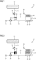
- FIG 1 illustrates a schematic front view of a steam generating system 10 for a cooking oven with steam cooking function according to a preferred embodiment of the present invention.
- the steam generating system 10 comprises a water tank 12, a water loading tube 14, an inlet valve 16, a control chamber 18, a descaling actuator 26, a water tube 28, a steam generator 30 and a steam nozzle 38.
- the control chamber 18 includes a water level sensor 20.
- the water level sensor 20 is arranged inside the control chamber 18.
- the water level sensor 20 is arranged upon said control chamber 18.
- the steam generator 30 includes a heating element 32, a limiting sensor 34 and a condenser 36.
- the steam generating system 10 comprises a control unit for activating and deactivating the steam generator 30 and for opening and closing the inlet valve 16, wherein said control unit is not explicitly shown in FIG 1 .
- the water tank 12 is connected to the inlet valve 16 via the water loading tube 14.
- the inlet valve 16 is connected to the control chamber 18.
- the control chamber 18 may be integrated with the inlet valve 16.
- the control chamber 18 is connected to the steam generator 30 via the water tube 28. Further, said water tube 28 is connected to a drain 24 of the oven cavity via the descaling actuator 26.
- the control chamber 18 and the steam generator 30 are arranged at the same level.
- the control chamber 18, the water tube 28 and the steam generator 30 form communicating vessels.
- a water level 22 in the control chamber 18 corresponds with the water level 22 in the steam generator 30.
- the water level sensor 20 in the control chamber 18 detects factually the water level 22 in the steam generator 30.
- the water level sensor 20 is a capacitive sensor.
- the water level sensor 20 may be an arbitrary sensor suitable for detecting the water level. In FIG 1 the water level 22 has the maximum value.
- control chamber 18 and the steam generator 30 are connected to the drain of the oven cavity via the water tube 28 and the descaling actuator 26.
- the steam generator 30 may be L-shaped, linear, square or rectangular.
- the limiting sensor 34 acts as a safety device for the steam generator 30.
- FIG 2 illustrates a schematic front view of the steam generating system 10 for the cooking oven with steam cooking function according to the preferred embodiment of the present invention.
- the water level 22 in the control chamber 18 and the steam generator 30 has the minimum value.
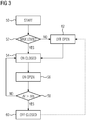
- FIG 3 illustrates a schematic flow chart diagram of the method for controlling the steam generating system 10 of the cooking oven with steam cooking function according to the preferred embodiment of the present invention.
- the method is started.
- a step 52 it is checked, if the water level 22 in the control chamber 18 and in the steam generator 30 is at the maximum level. If the water level 22 is at the maximum level, then the steam generator 30 is activated and the inlet valve 16 is closed in a step 54. When the water level 22 reaches the minimum level in the control chamber 18 and the steam generator 30, then in a step 56 the inlet valve 16 is opened, while the steam generator 30 remains activated.
- a step 58 it is checked, if the time ⁇ t for refilling the steam generator 30 is bigger than the threshold time value ⁇ ts for refilling said steam generator 30. If the time ⁇ t for refilling the steam generator 30 exceeds said threshold time value ⁇ ts, then the steam generator 30 is deactivated and the inlet valve 16 is closed in a step 60. In a next step 62, the inlet valve 16 is opened again, while the steam generator 30 remains deactivated. Then, the steam generator 30 is activated again and the inlet valve 16 is closed again in the step 54.
- the time ⁇ t for refilling the steam generator 30 is lower than the threshold time value ⁇ ts, then the steam generator 30 remains activated, but the inlet valve 16 is closed again in the step 54. Then, the method is set forth by the steps 56 and 58 again.
- FIG 4 illustrates a schematic perspective view of the steam generating system 10 for the cooking oven with steam cooking function according to the prior art.
- the steam generating system 10 of the prior art comprises the water tank 12, the water loading tube 14, the inlet valve 16, an air tube 40, a drain valve 42, a multi-connection tube 44, the steam generator 30 and the steam nozzle 38.
- the steam generator 30 includes a first thermal sensor 46 and a second thermal sensor 48 arranged within and/or at said steam generator 30.
- the drain valve 42 is connected to the drain 24 of the oven cavity.
- the water tank 12 is connected to the inlet valve 16 via the water loading tube 14.
- the drain valve 42 is connected to the drain 24 of the oven cavity.
- the outlets of the inlet valve 16 and drain valve 42 are connected to the steam generator 26 via the multi-connection tube 44.
- the air tube 40 is interconnected between the multi-connection tube 44 and the oven cavity.
- the steam generator 30 is connected to the oven cavity via the steam nozzle 38.
- the water tank 12 is arranged above the inlet valve 16, so that the water is delivered by gravity from the water tank 12 through the water loading tube 14 to the inlet valve 16.
- the drain valve 42 remains in the closed state, unless a drain or service function is activated.
- FIG 5 illustrates a schematic flow chart diagram of the method for controlling the steam generating system 10 of the cooking oven with steam cooking function according to the prior art.
- the method is started.
- a step 64 it is checked, if the detected temperature T is higher than a set threshold temperature value Ts. If the detected temperature T is higher than the set threshold temperature value Ts, then the inlet valve 16 is opened in a step 66. During next step 68 said inlet valve 68 remains open for a predetermined time frame. Then, the inlet valve 16 is closed in a step 70. Then, the steam generator 30 is activated in a step 72.
- the steam generator 30 is activated in the step 72.
- the inlet valve 16 is turned on for a fixed time. If the steam generator 30 is not cooled down, the inlet valve 16 will be opened for said fixed time only. When there is lack of water in the steam generator 30, then said steam generator 30 remains activated and temperature peaks occur. Since the quantity of water is minimal, this results in loss of energy. Moreover, the system of the prior art requires a digital control unit and a continuous control of the temperature.
- the method and system according to the present invention avoid temperature peaks in the steam generator 30, since said steam generator 30 works only, if there is sufficient water therein. When lack of water is detected, then the system is refilled with water. The supply of water is interrupted only, if the water level 22 is at its maximum value. Further, the number of the openings and closings of the inlet valve 16 is minimised.
Landscapes
- Engineering & Computer Science (AREA)
- Chemical & Material Sciences (AREA)
- Combustion & Propulsion (AREA)
- Mechanical Engineering (AREA)
- General Engineering & Computer Science (AREA)
- Life Sciences & Earth Sciences (AREA)
- Food Science & Technology (AREA)
- Cookers (AREA)
Priority Applications (1)
| Application Number | Priority Date | Filing Date | Title |
|---|---|---|---|
| EP18189168.0A EP3610732A1 (de) | 2018-08-15 | 2018-08-15 | Verfahren zur steuerung eines dampferzeugungssystems für einen garofen mit dampffunktion und dampferzeugungssystem |
Applications Claiming Priority (1)
| Application Number | Priority Date | Filing Date | Title |
|---|---|---|---|
| EP18189168.0A EP3610732A1 (de) | 2018-08-15 | 2018-08-15 | Verfahren zur steuerung eines dampferzeugungssystems für einen garofen mit dampffunktion und dampferzeugungssystem |
Publications (1)
| Publication Number | Publication Date |
|---|---|
| EP3610732A1 true EP3610732A1 (de) | 2020-02-19 |
Family
ID=63294008
Family Applications (1)
| Application Number | Title | Priority Date | Filing Date |
|---|---|---|---|
| EP18189168.0A Pending EP3610732A1 (de) | 2018-08-15 | 2018-08-15 | Verfahren zur steuerung eines dampferzeugungssystems für einen garofen mit dampffunktion und dampferzeugungssystem |
Country Status (1)
| Country | Link |
|---|---|
| EP (1) | EP3610732A1 (de) |
Cited By (2)
| Publication number | Priority date | Publication date | Assignee | Title |
|---|---|---|---|---|
| EP4050267A1 (de) | 2021-02-25 | 2022-08-31 | Electrolux Appliances Aktiebolag | Kochherd |
| EP4428446A1 (de) * | 2023-03-09 | 2024-09-11 | Electrolux Appliances Aktiebolag | Dampferzeugungsvorrichtung für einen haushaltsofen |
Citations (6)
| Publication number | Priority date | Publication date | Assignee | Title |
|---|---|---|---|---|
| US20060000821A1 (en) * | 2004-06-30 | 2006-01-05 | Davide Gerola | Oven with a system for generating steam |
| WO2007015398A1 (ja) * | 2005-08-01 | 2007-02-08 | Sharp Kabushiki Kaisha | 加熱調理器 |
| US7537004B2 (en) * | 2005-05-03 | 2009-05-26 | Whirlpool Corporation | Steam oven with fluid supply and drain vessel |
| EP2518413A2 (de) * | 2011-04-28 | 2012-10-31 | Samsung Electronics Co., Ltd. | Dampfkochvorrichtung |
| US20170164778A1 (en) * | 2014-09-05 | 2017-06-15 | Sharp Kabushiki Kaisha | Steam generating apparatus and heating cooker |
| US20180070596A1 (en) * | 2016-09-09 | 2018-03-15 | Samsung Electronics Co., Ltd. | Cooking appliance and method for controlling the same |
-
2018
- 2018-08-15 EP EP18189168.0A patent/EP3610732A1/de active Pending
Patent Citations (6)
| Publication number | Priority date | Publication date | Assignee | Title |
|---|---|---|---|---|
| US20060000821A1 (en) * | 2004-06-30 | 2006-01-05 | Davide Gerola | Oven with a system for generating steam |
| US7537004B2 (en) * | 2005-05-03 | 2009-05-26 | Whirlpool Corporation | Steam oven with fluid supply and drain vessel |
| WO2007015398A1 (ja) * | 2005-08-01 | 2007-02-08 | Sharp Kabushiki Kaisha | 加熱調理器 |
| EP2518413A2 (de) * | 2011-04-28 | 2012-10-31 | Samsung Electronics Co., Ltd. | Dampfkochvorrichtung |
| US20170164778A1 (en) * | 2014-09-05 | 2017-06-15 | Sharp Kabushiki Kaisha | Steam generating apparatus and heating cooker |
| US20180070596A1 (en) * | 2016-09-09 | 2018-03-15 | Samsung Electronics Co., Ltd. | Cooking appliance and method for controlling the same |
Cited By (3)
| Publication number | Priority date | Publication date | Assignee | Title |
|---|---|---|---|---|
| EP4050267A1 (de) | 2021-02-25 | 2022-08-31 | Electrolux Appliances Aktiebolag | Kochherd |
| WO2022179816A1 (en) | 2021-02-25 | 2022-09-01 | Electrolux Appliances Aktiebolag | Cooking oven |
| EP4428446A1 (de) * | 2023-03-09 | 2024-09-11 | Electrolux Appliances Aktiebolag | Dampferzeugungsvorrichtung für einen haushaltsofen |
Similar Documents
| Publication | Publication Date | Title |
|---|---|---|
| EP3205936B1 (de) | Verbrennungswassererhitzer | |
| EP3188624B1 (de) | Dampfinjektionssystem und verfahren | |
| CA2965534C (en) | Steam cooking oven with temperature sensor in vent stack, and method of controlling steam production thereof | |
| KR20060115333A (ko) | 스팀 오븐으로부터 물을 배출하기 위한 시스템 및 방법 | |
| CN104026995A (zh) | 具有气候受控温度限制器的烤箱 | |
| US20060000821A1 (en) | Oven with a system for generating steam | |
| EP3610732A1 (de) | Verfahren zur steuerung eines dampferzeugungssystems für einen garofen mit dampffunktion und dampferzeugungssystem | |
| EP1956299A1 (de) | Heizkocher | |
| EP1735569B1 (de) | Wasserheizer und betriebsverfahren dafür | |
| EP1975516B1 (de) | Garofen und Betriebsverfahren dafür | |
| KR102369153B1 (ko) | 전기 조리기 | |
| DK2474787T3 (en) | Steam cooking apparatus | |
| US12044401B2 (en) | Method for controlling a steam generating system for a domestic steam cooking oven and steam generating system | |
| AU2012268875B2 (en) | Multi function cooking device | |
| US20230061871A1 (en) | Steam oven steam generator with heater control | |
| KR101512597B1 (ko) | 냉수 제어 기능이 향상된 금형 온도조절장치 | |
| GB2520064A (en) | Heating control systems | |
| KR102838130B1 (ko) | 파우셋부가 구비된 전기레인지를 이용한 자동조리 제어방법 | |
| KR20120095228A (ko) | 일정온도의 온수 공급이 가능한 온수 공급시스템 | |
| JP5256116B2 (ja) | 加熱殺菌装置 | |
| CA3170791C (en) | Steam oven steam generator with heater control | |
| CN114468753B (zh) | 烹饪器具的无水焗烹饪方法、烹饪器具 | |
| CN110613328B (zh) | 用于烹饪器具的保护方法、系统及烹饪器具 | |
| CN110207083A (zh) | 可控蒸汽发生装置及其控制方法 | |
| JP2005152196A (ja) | 炊飯器 |
Legal Events
| Date | Code | Title | Description |
|---|---|---|---|
| PUAI | Public reference made under article 153(3) epc to a published international application that has entered the european phase |
Free format text: ORIGINAL CODE: 0009012 |
|
| STAA | Information on the status of an ep patent application or granted ep patent |
Free format text: STATUS: THE APPLICATION HAS BEEN PUBLISHED |
|
| AK | Designated contracting states |
Kind code of ref document: A1 Designated state(s): AL AT BE BG CH CY CZ DE DK EE ES FI FR GB GR HR HU IE IS IT LI LT LU LV MC MK MT NL NO PL PT RO RS SE SI SK SM TR |
|
| AX | Request for extension of the european patent |
Extension state: BA ME |
|
| STAA | Information on the status of an ep patent application or granted ep patent |
Free format text: STATUS: REQUEST FOR EXAMINATION WAS MADE |
|
| 17P | Request for examination filed |
Effective date: 20200819 |
|
| RBV | Designated contracting states (corrected) |
Designated state(s): AL AT BE BG CH CY CZ DE DK EE ES FI FR GB GR HR HU IE IS IT LI LT LU LV MC MK MT NL NO PL PT RO RS SE SI SK SM TR |
|
| STAA | Information on the status of an ep patent application or granted ep patent |
Free format text: STATUS: EXAMINATION IS IN PROGRESS |
|
| 17Q | First examination report despatched |
Effective date: 20220426 |