EP3610988A1 - Dispositif de pression à fixation à boulon centrée - Google Patents
Dispositif de pression à fixation à boulon centrée Download PDFInfo
- Publication number
- EP3610988A1 EP3610988A1 EP18189518.6A EP18189518A EP3610988A1 EP 3610988 A1 EP3610988 A1 EP 3610988A1 EP 18189518 A EP18189518 A EP 18189518A EP 3610988 A1 EP3610988 A1 EP 3610988A1
- Authority
- EP
- European Patent Office
- Prior art keywords
- bolt
- securing element
- securing
- centering
- press device
- Prior art date
- Legal status (The legal status is an assumption and is not a legal conclusion. Google has not performed a legal analysis and makes no representation as to the accuracy of the status listed.)
- Granted
Links
Images


Classifications
-
- B—PERFORMING OPERATIONS; TRANSPORTING
- B25—HAND TOOLS; PORTABLE POWER-DRIVEN TOOLS; MANIPULATORS
- B25B—TOOLS OR BENCH DEVICES NOT OTHERWISE PROVIDED FOR, FOR FASTENING, CONNECTING, DISENGAGING OR HOLDING
- B25B27/00—Hand tools, specially adapted for fitting together or separating parts or objects whether or not involving some deformation, not otherwise provided for
- B25B27/02—Hand tools, specially adapted for fitting together or separating parts or objects whether or not involving some deformation, not otherwise provided for for connecting objects by press fit or detaching same
- B25B27/10—Hand tools, specially adapted for fitting together or separating parts or objects whether or not involving some deformation, not otherwise provided for for connecting objects by press fit or detaching same inserting fittings into hoses
-
- B—PERFORMING OPERATIONS; TRANSPORTING
- B21—MECHANICAL METAL-WORKING WITHOUT ESSENTIALLY REMOVING MATERIAL; PUNCHING METAL
- B21D—WORKING OR PROCESSING OF SHEET METAL OR METAL TUBES, RODS OR PROFILES WITHOUT ESSENTIALLY REMOVING MATERIAL; PUNCHING METAL
- B21D39/00—Application of procedures in order to connect objects or parts, e.g. coating with sheet metal otherwise than by plating; Tube expanders
- B21D39/04—Application of procedures in order to connect objects or parts, e.g. coating with sheet metal otherwise than by plating; Tube expanders of tubes with tubes; of tubes with rods
- B21D39/048—Application of procedures in order to connect objects or parts, e.g. coating with sheet metal otherwise than by plating; Tube expanders of tubes with tubes; of tubes with rods using presses for radially crimping tubular elements
Definitions
- the present invention relates to a pressing device according to the preamble of claim 1.
- Press devices are known from the prior art and are used, for example, in the electrical field or in pipeline construction to create press connections.
- the individual parts of the pressing devices are often assembled using releasable connecting means such as screws, snap rings or circlips or snap-on caps.
- centering means a correct alignment of the securing element with respect to the bolt and also a correct fastening of the securing element by means of the fastening element both in the axial direction and in a direction running radially to a central axis of the bolt.
- Correct alignment is achieved, for example, when the securing element is mounted on the bolt in a linear manner, that is to say, for example, not inclined or tilted or tilted.
- correct fastening is achieved, for example, when the fastening element, and consequently the securing element, is fastened linearly to the bolt.
- the at least one centering element thus enables improved assembly.
- the bolt is thus held in the pressing device by the securing element.
- This is preferably a pressing device comprising a non-releasable securing element according to EP 3 231 528 A1 , the content of which is hereby incorporated into this application.
- the non-releasable securing element prevents removal or replacement of the bolt, as a result of which the above-mentioned disadvantages in connection with releasable connecting means are avoided.
- a pressing device with firmly assembled individual parts is made available in this way, which cannot be opened after the initial assembly.
- the term "non-detachable" is thus understood to mean that the securing element can only be separated with increased effort with the aid of tools which destroy or damage the securing element or the bolts.
- the pressing device and its components can therefore have the form of pressing devices known per se from the prior art. It is conceivable that the pressing device has the shape of a pressing loop and the pressing element is designed in the form of an intermediate jaw. It is also conceivable for two press elements to be provided in the form of press levers and for the support element to have two support openings, one bolt each extending through one of the support openings and one of the bearing openings.
- the securing element can be a securing element placed on a bolt end, which at least partially, preferably completely, surrounds the bolt end. So so it is conceivable that the securing element z. B. is cap-shaped or annular, the bolt end being received in the interior thereof. This means that the securing element can have the shape of an end cap, which completely receives and surrounds the bolt end, or the securing element can have the shape of a closing ring, which surrounds the outside of the bolt end.
- the securing element preferably has an interior space delimited by an inner wall for receiving the bolt end, wherein at least one fastening element acting on the bolt end, in particular on the lateral surface of the bolt end, is arranged in the interior.
- the fastening element could be a snap ring or spring ring which is placed in a groove running around the inner wall, which snap ring or spring ring engages in a groove which extends around the circumference of the bolt.
- the spring ring or snap ring can be preassembled in the securing element, i.e. placed in its groove before the end cap or end ring is attached, so that when the end cap or end ring is attached to the bolt end, this spring ring engages or snaps into the groove at the bolt end ,
- the above-mentioned fastening elements have the particular advantage that they enable a stronger connection between the securing element and the bolt, and thereby bring about additional securing relating to an unwanted release of the securing element from the bolt.
- the at least one centering element can have the shape of a stop and, when the at least one securing element is connected to the at least one bolt, can provide a stop for the at least one fastening element.
- the at least one centering element and the at least one securing element can be formed in one piece.
- the at least one centering element can be arranged on an inner wall of the at least one securing element, and an inner diameter of the at least one securing element in the region of the at least one centering element is smaller than a diameter of the at least one bolt.
- this securing element is a stop on the inner wall of the securing element, the stop projecting from this inner wall into the interior of the securing element.
- the stop in this case is an element that protrudes or protrudes from the inner wall.
- the inside diameter is the clear dimension. This means that the securing element in the area of the stop preferably defines a clear dimension or an opening which is smaller than the diameter of the bolt.
- the at least one securing element can have a recess, the at least one centering element being deformable, and the at least one centering element being at least partially bent into the recess when the at least one securing element is connected to the at least one bolt.
- the securing element can have a recess in the form of an undercut.
- This undercut is preferably located in a distal region of the securing element, that is to say in the region which, in the case of a received bolt end, faces away from the bolt end.
- the inner diameter of the securing element in the region of the stop is preferably smaller than the diameter of the bolt. If the securing element is now placed on the bolt, the deformable stop is increasingly bent or bent in the direction of the distal end of the securing element and is thereby increasingly received in the undercut.
- the recess or undercut preferably has a diameter which is essentially the same size or larger than the diameter of the bolt.
- the at least one securing element can have a groove on its inner wall, which extends at least partially along the circumferential direction around the at least one securing element, and the at least one fastening element is at least partially received in the groove of the at least one securing element.
- the centering element in the form of the stop prevents the fastening element from coming out of the groove of the securing element when the securing element is connected to the bolt.
- the stop forms a counter surface for the fastening element and, when the securing element snaps out onto the bolt, ensures the necessary counter pressure against the fastening element, so that it is not pushed away but remains in its central position and is therefore correctly aligned and securely in the groove of the bolt can snap.
- the pressing device can have a centering element according to the first aspect as described above or a centering element according to a second aspect as described below.
- the pressing device preferably has both a centering element according to the first aspect and a centering element according to the second aspect.
- the following explanations regarding the centering element relate to the centering element according to the second aspect.
- the at least one centering element can have the shape of a hollow body and at least partially surround the at least one fastening element along its circumferential direction.
- the fastening element is preferably completely surrounded by the centering element.
- the at least one fastening element can be arranged at least partially, preferably completely, within this centering element.
- the at least one centering element can have an inner diameter which is the same size or larger than an outer diameter of the fastening element. If the inner diameter of the centering element is the same size or substantially the same size as the outer diameter of the fastening element, the centering element and the fastening element adjoin one another at least in the non-connected state of the securing element and the bolt. Is the inside diameter of the Centering element larger than the outer diameter of the fastening element, there is a lateral distance between the fastening element and the centering element, at least in the unconnected state.
- the at least one centering element can be arranged within the groove of the at least one securing element.
- the groove is preferably a profile structure with a profile base and two adjacent profile walls. Because the centering element at least partially surrounds the fastening element along its circumferential direction, the centering element received within the groove is consequently arranged in the region of the profile base, while the fastening element is arranged in the region of the profile opening opposite the profile base. The centering element thus aligns the fastening element within the groove of the securing element and ensures that this correct alignment is maintained even when the securing element is connected to the bolt. This also ensures correct alignment of the securing element attached to the bolt.
- the at least one centering element and the at least one fastening element can be arranged concentrically to one another.
- the centering element preferably has an annular or hollow cylindrical shape, within which the preferably essentially annular fastening element in the form of the snap ring or spring ring is arranged.
- the at least one centering element can be elastic and in particular consist of an elastomer.
- the centering element is preferably an O-ring which is arranged around the snap ring or spring ring.
- the at least one bolt and the at least one fastening element can each have a guide surface, and the guide surface of the at least one bolt and the guide surface of the at least one fastening element provide a guided connection of the at least one securing element to the at least one bolt at least in regions.
- the guide surface of the fastening element is preferably the outer surface of the fastening element facing the bolt.
- the guide surface of the at least one bolt is preferably inclined with respect to a central axis through the bolt, so that the at least one fastening element is moved radially outward along the inclined guide surface of the bolt during the connection of the at least one securing element to the at least one bolt.
- the at least one bolt preferably has a groove which extends at least partially around the bolt along a circumferential direction, and the at least one fastening element in an end state in which the at least one securing element is connected to the at least one bolt, at least partially in the groove of the bolt is received.
- the bolt therefore preferably has a reduced cross section in the region of its free ends.
- the fastening element in turn, preferably has an inner diameter which is smaller than the diameter of the bolt in the unconnected state.
- the fastening element is pressed against the O-ring, the O-ring being compressed due to its elastic design. If the securing element is now advanced further along the bolt, the fastening element snaps into the groove in the bolt. The securing element is then fixed to the bolt.
- the at least one securing element can consist of a material comprising steel and in particular a compressive strength of approximately 500 to 2000 N / mm 2 , preferably of approximately 800 to 1600 N / mm 2 in the hardened state and / or an elongation at break of approximately 2 to 20%, preferably have from about 5 to 15%.
- FIG. 1 to 6c a first embodiment of a pressing device 1 with a bolt fixation comprising securing elements 11, 11 ', centering elements 27, 27'; 28, 28 'and fasteners 18, 18' and in the Figures 7 to 9 a second embodiment of a pressing device 1 'with a bolt fixation comprising securing elements 12, 12', centering elements 27, 27 '; 28, 28 'and fasteners 18, 18' shown.
- the two pressing devices 1, 1 ' essentially differ from one another only in the design of the securing elements 11, 11' and 12, 12 '. It is therefore to be understood that explanations regarding the pressing device 1 according to the first embodiment also refer to the pressing device 1 'according to the second embodiment, and vice versa.
- the pressing device 1 comprises two pressing levers 5, 5 ', two pressing jaws 4, 4' and a carrier element 2.
- the carrier element 2 is here essentially T-shaped and has two carrier openings 3, 3 '.
- the two press elements in the form of press levers 5, 5 ' are of identical design and each have a bearing opening 6, 6', the press levers 5, 5 'being pivotably mounted on the carrier element 2 via a respective pivot axis A1, A2.
- One press lever 5 can be pivoted about the first pivot axis A1 and the other press lever 5 'about the second pivot axis A2 from an initial position to a press position.
- a bolt 8, 8 'providing the bearing and the pivot axis A1, A2 extends through one of the carrier openings 3, 3' and one of the bearing openings 6, 6 '.
- the bolt 8, 8 ' is secured at the end with a non-releasable securing element 11, 11' with respect to an axial displacement in the bearing opening 6, 6 'and in the carrier opening 3, 3'.
- the press levers 5, 5 'each have a press jaw receptacle 22, 22' with a receiving surface into which the press jaws 4, 4 'are inserted.
- the press contours 23, 23 'are essentially concave, so that a part to be pressed, such as a fitting to be pressed, can be pressed through the press contour 23, 23'.
- the bolt 8, 8 'thus serves for the pivotable mounting of the press levers 5, 5' on the carrier element and at the same time provides the pivot axes A1, A2 about which the press levers 5,5 'are pivoted.
- the two bolts 8, 8 ' are each secured at the end with a non-releasable securing element 11, 11' in the bearing openings 6, 6 'and the carrier openings 3, 3'.
- the bolt 8 is cylindrical and has a constant diameter DB and a full cross section over a large part of its length.
- the surfaces of the press lever 5 each lie flush on the surface of the first or second carrier element 2, 2 'and the inner surfaces of the carrier openings 3 or bearing openings 6 and the outer surface 10 of the bolt 8 are in surface contact with one another.
- this embodiment is a securing element 11, 11 'in the form of an end cap which is placed on the bolt end 9, 9'.
- the securing element 11, 11 ' comprises an inner wall 14, 14' which defines an interior 16, 16 'for receiving the bolt end 9, 9'.
- the distal end of the securing element, or in other words the bottom surface 24, 24 'of the cap-shaped securing element, is planar and extends in each case perpendicular to the pivot axes A1, A2 or parallel to a plane of the carrier element 2.
- the bolt end 9, 9 ' is received in the interior 16, 16' of the securing element 11, 11 ', the inner wall 14, 14' completely surrounding these parts of the bolt 8, 8 'which project from the carrier element 2.
- the bolt end 9, 9 ' thus completely enclosed by the cap-shaped securing element 11, 11'.
- the securing element 11, 11 ' has an outer wall 25, 25' on the outside, which is in each case frustoconical about the said pivot axis A1, A2.
- the outer wall is formed with a curve which has the shape of an arc in cross section.
- the snap ring or spring washer 18, 18 ' is placed in a groove 19, 19' running around the inner wall 14, 14 'of the securing element and engages in a groove or groove extending around the circumference of the bolt 8, 8' 21, 21 'of the bolt 8, 8'.
- the snap ring or spring ring can be essentially semicircular and have an interruption (see e.g. Figure 1 ).
- fastening elements 18, 18 ' serve to additionally secure the securing elements 11, 11', 12, 12 'on the bolts 8, 8' and are each pre-assembled in the securing elements 11, 11 ', 12', 12 '.
- the pressing devices 1, 1 have 'further via centering elements 27, 27', 28, 28 ', which center the securing elements 11, 11', 12, 12 'and / or the fastening elements 18, 18' on the bolts 8, 8 '.
- centering here includes correct alignment of the securing elements 11, 11 ', 12, 12' with respect to the bolts 8, 8 'and correct fastening of the securing elements 11, 11', 12, 12 'by means of the fastening elements 18, 18 'to be understood both in the axial direction and in a radial direction with respect to the central axis MB of the bolts 8, 8'.
- the pressing device 1 has two centering elements 27, 27 '; 28, 28 ', namely a first centering element 27, 27' in the form of a stop and a second centering element 28, 28 'in the form of a hollow body.
- the pressing device 1 has only the first centering element 27, 27 'or only the second centering element 28, 28'.
- the centering element 27, 27 'in the form of the stop serves to provide a stop for the fastening element 18, 18' when the securing element 11, 11 'is connected to the bolt 8, 8'.
- the stop 27, 27 ' is formed on the inner wall 14, 14' of the securing element 11, 11 'and, starting from this inner wall 14, 14', projects into the interior of the securing element 11, 11 '.
- the stop 27, 27 'and the securing element 11, 11' are formed in one piece. This means that the stop 27, 27 'is an integral part of the securing element 11, 11', more precisely the inner wall 14, 14 'of the securing element 11, 11'.
- the inside diameter is the clear dimension.
- the securing element 11, 11 ' has a recess 29, 29' in the form of an undercut.
- the undercut 29, 29 ' is, starting from the bottom surface 24, 24' of the securing element 11, 11 'in the direction of an insertion opening 13, 13' of the securing element 11, 11 'seen in front of the stop 27, 27', which in turn is located in front of the groove 19, 19 '.
- the stop 27, 27 ' is formed between the undercut 29, 29' and the groove 19, 19 '.
- the inner diameter DSIA of the securing element 11, 11 'in the region of the stop 27, 27' is smaller than the inner diameter DSIH of the securing element 11, 11 'in the region of the undercut 29, 29' and also smaller than the inner diameter DSIN of the securing element 11 , 11 'in the area of the groove 19, 19'.
- the stop 27, 27 ' prevents that the fastening element 18, 18 'can come out of the groove 19, 19' of the securing element 11, 11 'when the securing element 11, 11' is connected to the bolt 8, 8 '.
- the stop 27, 27 ' forms a counter surface for the fastening element 18, 18' and, when the securing element 11, 11 'snaps out on the bolts 8, 8', ensures the required counter pressure against the fastening element 18, 18 ', so that this is not pushed away but remains in its central position and can thus snap securely into the groove 21, 21 'of the bolt 8, 8'.
- the inner diameter DSIA of the securing element 11 in the area of the stop 27 is smaller than the diameter DB of the bolt 8. If the securing element 11 is now placed on the bolt 8, the stop 27 is increasingly bent in the direction of the bottom surface 24 of the securing element 11 or bent and recorded in the undercut 29.
- the bolt end 9 is given a place in the interior of the securing element 11 at a point in time where the fastening element 18 has already snapped securely into the groove 21 of the bolt 8.
- the free bolt end 9 borders directly on the bottom surface 24 of the securing element 11.
- a centering element 28, 28 'in the form of a hollow body, which extends along a circumferential direction of the fastening element 18, 18' around the fastening element can be present .
- the hollow body 28, 28 ' has an inner diameter DSZ which is the same size or larger than the outer diameter DBA of the fastening element 18, 18'.
- this centering element 28, 28 ' is preferably an O-ring, that is to say an elastic element with an essentially circular cross section.
- the O-ring 28, 28 ' is also arranged in the groove 19, 19' of the securing element 11, 11 ', the O-ring 28, 28' and the fastening element 18, 18 'being concentric to one another.
- the O-ring 28, 28 'thus aligns the fastening element 18, 18' within the groove 19, 19 'of the securing element 11, 11' and, as will be explained below, ensures that this correct alignment also during the connection of the securing element 11, 11 'with the bolt 8, 8' is maintained.
- a correct one Alignment of the securing element 11, 11 'attached to the bolt 8, 8' is also ensured in this way.
- the O-ring 28, 28 'thus centers the fastening element 18, 18'.
- the bolt 8 each has inclined guide surfaces 30, which interact with the fastening element 18 and thereby permit a guided connection between the securing element 11 and the bolt 8, see Figures 6a to 6c , Starting from the groove 21 in the bolt 8 in the direction of the free ends 9 of the bolt 8, these guide surfaces 30 run against one another in the direction of the central axis MB of the bolt 8.
- the bolt 8 thus has a reduced cross section in the region of its free ends 9.
- the outer surfaces 31 of the fastening elements 18 thus serve as guide surfaces which interact with the inclined guide surfaces 30 of the bolts 8.
- the fastening element 18 is pressed against the O-ring 28, the O-ring 28 being compressed due to its elastic design (see Figure 6b ).
- both the O-ring 28 and the fastening element 18 are completely accommodated in the groove 19 of the securing element 11, the stop 27 preventing these components from moving out of the groove 19. If the securing element 11 is now advanced further over the bolt 8, the fastening element 18 snaps into the groove 21 in the bolt 8 (see Figure 6c ).
- the O-ring 28 is then again in its unpressed state within the groove 19 of the securing element 11 and prevents the fastening element 18 from moving out of the groove 21 of the bolt 8.
- the stop 27, which was increasingly bent during sliding along the inclined guide surfaces 30 of the bolt 8 is in the undercut 29.
- the pressing device 1 has only one centering element 28 in the form of the hollow body , it is conceivable to provide the securing element 1 only with the groove 19 but for example without a stop 27 and in particular without an undercut 29.
- Bolt fixation shown is only on one side of the bolt 8, a non-releasable securing element 11.
- the bolt 8 in use has a securing element 11, 11 'on both sides, which prevents axial displacement of the bolt in the carrier elements 2, 2' and in the press lever 5 on both sides.
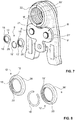
- FIGS. 7 to 9 each show a further preferred embodiment of a pressing device 1 'with a pin fixation according to the invention.
- the same elements are provided with the same reference numerals.
- Unlike the press device 1 in the Figures 1-6c extends in the pressing device 1 'according to the Figures 7 to 9 in each case one bolt 8, 8 'through the carrier openings 3, 3' and bearing openings 6, 6 ', which end is secured with an annular, non-releasable securing element 12, 12' with respect to an axial displacement.
- this securing element 12, 12 'in the form of an end ring has an inner wall 15, 15' which has an inner space 17, 17 'for receiving the bolt end 9, 9'.
- a securing part 18, 18' in the form of a spring ring or snap ring, which acts on the bolt end, in particular on the lateral surface 10, 10 'of the bolt end, which in a circumferential manner around the bolt 8, 8' around recess or groove 21, 21 'engages or. snaps into this.
- the spring ring or snap ring is placed in a circumferential groove 20, 20 'of the end ring 12, 12' in the inner wall 15, 15 '.
- the end rings also have centering elements in the form of the stop and in the form of the hollow body as described above.
- the outer wall 26, 26 ' cannot be gripped or cannot be effectively gripped by a plier-like tool
- the outer wall' 26, 26 'of the end ring around the swivel axis A1, A2 is also frustoconical here and has a rounded shape, which has a multi-part cross section Arch trained.
- the axial displacement of the bolt 8, 8' can take place by means of an end ring 12, 12 'attached to the bolt on both sides, the bolt passing through the carrier opening 3 of a first carrier element 2, through the bearing opening 6 of the press lever 5 and extends through the carrier opening of a second carrier element 2 'and is secured on its distal bolt end 9 as well as on its proximal bolt end 9' with an end ring 12, 12 '.
- the bolt 8 is also cylindrical and has a constant diameter DB and a full cross section over a large part of its length.
- the end ring 12, 12 ' in contrast to the end cap 11, 11', has no bottom surface which covers the surface of the bolt end 9, 9 '.
- the end cap 11, 11 ' has a bottom surface 24, 24' and the parts of the bolt 8, 8 'projecting from the carrier element 2 are completely surrounded by the inner wall 14, 14'
- the end ring 12, 12 ' encloses this protruding parts at least partially, namely completely around the outer surface 10, 10 'of the bolt ends 9, 9', the surfaces of the bolt ends 9, 9 'of the end ring 12, 12', however, in each case remain uncovered and free-standing.
- the above-mentioned aspects of the press device can also be used in the case of a press device in the form of a press loop. realize an intermediate jaw.
Landscapes
- Engineering & Computer Science (AREA)
- Mechanical Engineering (AREA)
- Connection Of Plates (AREA)
- Clamps And Clips (AREA)
Priority Applications (1)
| Application Number | Priority Date | Filing Date | Title |
|---|---|---|---|
| EP18189518.6A EP3610988B1 (fr) | 2018-08-17 | 2018-08-17 | Dispositif de pression à fixation à boulon centrée |
Applications Claiming Priority (1)
| Application Number | Priority Date | Filing Date | Title |
|---|---|---|---|
| EP18189518.6A EP3610988B1 (fr) | 2018-08-17 | 2018-08-17 | Dispositif de pression à fixation à boulon centrée |
Publications (2)
| Publication Number | Publication Date |
|---|---|
| EP3610988A1 true EP3610988A1 (fr) | 2020-02-19 |
| EP3610988B1 EP3610988B1 (fr) | 2021-12-22 |
Family
ID=63294161
Family Applications (1)
| Application Number | Title | Priority Date | Filing Date |
|---|---|---|---|
| EP18189518.6A Active EP3610988B1 (fr) | 2018-08-17 | 2018-08-17 | Dispositif de pression à fixation à boulon centrée |
Country Status (1)
| Country | Link |
|---|---|
| EP (1) | EP3610988B1 (fr) |
Cited By (1)
| Publication number | Priority date | Publication date | Assignee | Title |
|---|---|---|---|---|
| DE102022115433A1 (de) | 2022-06-21 | 2023-12-21 | Novopress Gmbh Pressen Und Presswerkzeuge & Co. Kommanditgesellschaft | Pressring, Pressschlinge und Presswerkzeug mit Verstellelement |
Citations (5)
| Publication number | Priority date | Publication date | Assignee | Title |
|---|---|---|---|---|
| EP1092487A2 (fr) | 1999-10-15 | 2001-04-18 | Gustav Klauke GmbH | Dispositif de pressage avec machoires de compression |
| EP1114698A2 (fr) * | 2000-01-07 | 2001-07-11 | Von Arx Ag | Pince à sertir |
| DE102012100357A1 (de) | 2012-01-17 | 2013-07-18 | Viega Gmbh & Co. Kg | Lösbare Werkzeugbackenhälfte |
| EP3231528A1 (fr) | 2016-04-12 | 2017-10-18 | Geberit International AG | Dispositif de pression comprenant une fixation a boulon |
| EP3246130A1 (fr) * | 2016-05-19 | 2017-11-22 | Geberit International AG | Dispositif de presse |
-
2018
- 2018-08-17 EP EP18189518.6A patent/EP3610988B1/fr active Active
Patent Citations (5)
| Publication number | Priority date | Publication date | Assignee | Title |
|---|---|---|---|---|
| EP1092487A2 (fr) | 1999-10-15 | 2001-04-18 | Gustav Klauke GmbH | Dispositif de pressage avec machoires de compression |
| EP1114698A2 (fr) * | 2000-01-07 | 2001-07-11 | Von Arx Ag | Pince à sertir |
| DE102012100357A1 (de) | 2012-01-17 | 2013-07-18 | Viega Gmbh & Co. Kg | Lösbare Werkzeugbackenhälfte |
| EP3231528A1 (fr) | 2016-04-12 | 2017-10-18 | Geberit International AG | Dispositif de pression comprenant une fixation a boulon |
| EP3246130A1 (fr) * | 2016-05-19 | 2017-11-22 | Geberit International AG | Dispositif de presse |
Cited By (1)
| Publication number | Priority date | Publication date | Assignee | Title |
|---|---|---|---|---|
| DE102022115433A1 (de) | 2022-06-21 | 2023-12-21 | Novopress Gmbh Pressen Und Presswerkzeuge & Co. Kommanditgesellschaft | Pressring, Pressschlinge und Presswerkzeug mit Verstellelement |
Also Published As
| Publication number | Publication date |
|---|---|
| EP3610988B1 (fr) | 2021-12-22 |
Similar Documents
| Publication | Publication Date | Title |
|---|---|---|
| DE112008004188B4 (de) | Befestigungsstruktur mit einer Durchgangstülle | |
| DE102007047860B3 (de) | Verbindungselement mit einer Schraube und einer daran unverlierbar angeordneten Hülse | |
| DE69807284T2 (de) | Verfahren zur Befestigung einer Lagerung einer Radnabe in ein Lagerhäuse einer Radaufhängung eines Fahrzeugs | |
| EP1608878B1 (fr) | Une connexion verrouillée entre arbre-moyeu | |
| DE69812324T2 (de) | Von Aussen einsteckbare Kugelrücklaufsysteme für Kugelumlaufspindeln und Verfahren zu deren Montage | |
| DE3843096C2 (de) | Befestigungseinrichtung für Verkleidungen | |
| EP0005865A2 (fr) | Système de liaison enfichable pour conduites sous pression, en particulier pour conduites de système de freinage | |
| DE3843095C2 (de) | Befestigungseinrichtung für Verkleidungen | |
| DE2813025C2 (de) | Sicherheitsbolzen | |
| WO2017162357A1 (fr) | Outil d'usinage par enlèvement de copeaux | |
| EP2047125A1 (fr) | Manchon | |
| DE4401622C2 (de) | Befestigungsvorrichtung für ein Montageglied einer Mutter-Schraube-Verbindung | |
| DE102010039793A1 (de) | Vorrichtung zur Verbindung zweier Bauteile | |
| EP2261519A2 (fr) | Vis destinée à la fixation d'un premier composant sur un second composant | |
| EP0275441B1 (fr) | Dispositif de serrage | |
| AT393302B (de) | Vorrichtung zur verbindung zweier werkzeugteile | |
| WO2018224237A1 (fr) | Moyens de serrage intérieur à bague segmentée de serrage bloquée | |
| DE102013100772A1 (de) | Steckverbindung für Fluid-Leitungen und Halteteil für eine derartige Steckverbindung | |
| EP1924378A1 (fr) | Dispositif pour realiser un couplage amovible de deux pieces | |
| EP2670993A2 (fr) | Cage à segments et procédé d'assemblage d'un palier à roulement | |
| EP3610988B1 (fr) | Dispositif de pression à fixation à boulon centrée | |
| DE4240605A1 (de) | Befestigungselement | |
| EP2082144A1 (fr) | Combinaison d'une vis et d'une douille et procédé de fabrication de cette combinaison | |
| DE3802154C2 (fr) | ||
| EP3231528B1 (fr) | Dispositif de pression comprenant une fixation à boulon |
Legal Events
| Date | Code | Title | Description |
|---|---|---|---|
| PUAI | Public reference made under article 153(3) epc to a published international application that has entered the european phase |
Free format text: ORIGINAL CODE: 0009012 |
|
| STAA | Information on the status of an ep patent application or granted ep patent |
Free format text: STATUS: THE APPLICATION HAS BEEN PUBLISHED |
|
| AK | Designated contracting states |
Kind code of ref document: A1 Designated state(s): AL AT BE BG CH CY CZ DE DK EE ES FI FR GB GR HR HU IE IS IT LI LT LU LV MC MK MT NL NO PL PT RO RS SE SI SK SM TR |
|
| AX | Request for extension of the european patent |
Extension state: BA ME |
|
| STAA | Information on the status of an ep patent application or granted ep patent |
Free format text: STATUS: REQUEST FOR EXAMINATION WAS MADE |
|
| 17P | Request for examination filed |
Effective date: 20200310 |
|
| RBV | Designated contracting states (corrected) |
Designated state(s): AL AT BE BG CH CY CZ DE DK EE ES FI FR GB GR HR HU IE IS IT LI LT LU LV MC MK MT NL NO PL PT RO RS SE SI SK SM TR |
|
| RIC1 | Information provided on ipc code assigned before grant |
Ipc: B25B 27/10 20060101AFI20210602BHEP Ipc: B21D 39/04 20060101ALI20210602BHEP |
|
| GRAP | Despatch of communication of intention to grant a patent |
Free format text: ORIGINAL CODE: EPIDOSNIGR1 |
|
| STAA | Information on the status of an ep patent application or granted ep patent |
Free format text: STATUS: GRANT OF PATENT IS INTENDED |
|
| INTG | Intention to grant announced |
Effective date: 20210713 |
|
| GRAS | Grant fee paid |
Free format text: ORIGINAL CODE: EPIDOSNIGR3 |
|
| GRAA | (expected) grant |
Free format text: ORIGINAL CODE: 0009210 |
|
| STAA | Information on the status of an ep patent application or granted ep patent |
Free format text: STATUS: THE PATENT HAS BEEN GRANTED |
|
| AK | Designated contracting states |
Kind code of ref document: B1 Designated state(s): AL AT BE BG CH CY CZ DE DK EE ES FI FR GB GR HR HU IE IS IT LI LT LU LV MC MK MT NL NO PL PT RO RS SE SI SK SM TR |
|
| REG | Reference to a national code |
Ref country code: GB Ref legal event code: FG4D Free format text: NOT ENGLISH |
|
| REG | Reference to a national code |
Ref country code: CH Ref legal event code: EP |
|
| REG | Reference to a national code |
Ref country code: DE Ref legal event code: R096 Ref document number: 502018008259 Country of ref document: DE |
|
| REG | Reference to a national code |
Ref country code: AT Ref legal event code: REF Ref document number: 1456788 Country of ref document: AT Kind code of ref document: T Effective date: 20220115 |
|
| REG | Reference to a national code |
Ref country code: IE Ref legal event code: FG4D Free format text: LANGUAGE OF EP DOCUMENT: GERMAN |
|
| REG | Reference to a national code |
Ref country code: LT Ref legal event code: MG9D |
|
| PG25 | Lapsed in a contracting state [announced via postgrant information from national office to epo] |
Ref country code: RS Free format text: LAPSE BECAUSE OF FAILURE TO SUBMIT A TRANSLATION OF THE DESCRIPTION OR TO PAY THE FEE WITHIN THE PRESCRIBED TIME-LIMIT Effective date: 20211222 Ref country code: LT Free format text: LAPSE BECAUSE OF FAILURE TO SUBMIT A TRANSLATION OF THE DESCRIPTION OR TO PAY THE FEE WITHIN THE PRESCRIBED TIME-LIMIT Effective date: 20211222 Ref country code: FI Free format text: LAPSE BECAUSE OF FAILURE TO SUBMIT A TRANSLATION OF THE DESCRIPTION OR TO PAY THE FEE WITHIN THE PRESCRIBED TIME-LIMIT Effective date: 20211222 Ref country code: BG Free format text: LAPSE BECAUSE OF FAILURE TO SUBMIT A TRANSLATION OF THE DESCRIPTION OR TO PAY THE FEE WITHIN THE PRESCRIBED TIME-LIMIT Effective date: 20220322 |
|
| REG | Reference to a national code |
Ref country code: NL Ref legal event code: MP Effective date: 20211222 |
|
| PG25 | Lapsed in a contracting state [announced via postgrant information from national office to epo] |
Ref country code: SE Free format text: LAPSE BECAUSE OF FAILURE TO SUBMIT A TRANSLATION OF THE DESCRIPTION OR TO PAY THE FEE WITHIN THE PRESCRIBED TIME-LIMIT Effective date: 20211222 Ref country code: NO Free format text: LAPSE BECAUSE OF FAILURE TO SUBMIT A TRANSLATION OF THE DESCRIPTION OR TO PAY THE FEE WITHIN THE PRESCRIBED TIME-LIMIT Effective date: 20220322 Ref country code: LV Free format text: LAPSE BECAUSE OF FAILURE TO SUBMIT A TRANSLATION OF THE DESCRIPTION OR TO PAY THE FEE WITHIN THE PRESCRIBED TIME-LIMIT Effective date: 20211222 Ref country code: HR Free format text: LAPSE BECAUSE OF FAILURE TO SUBMIT A TRANSLATION OF THE DESCRIPTION OR TO PAY THE FEE WITHIN THE PRESCRIBED TIME-LIMIT Effective date: 20211222 Ref country code: GR Free format text: LAPSE BECAUSE OF FAILURE TO SUBMIT A TRANSLATION OF THE DESCRIPTION OR TO PAY THE FEE WITHIN THE PRESCRIBED TIME-LIMIT Effective date: 20220323 |
|
| PG25 | Lapsed in a contracting state [announced via postgrant information from national office to epo] |
Ref country code: NL Free format text: LAPSE BECAUSE OF FAILURE TO SUBMIT A TRANSLATION OF THE DESCRIPTION OR TO PAY THE FEE WITHIN THE PRESCRIBED TIME-LIMIT Effective date: 20211222 |
|
| PG25 | Lapsed in a contracting state [announced via postgrant information from national office to epo] |
Ref country code: SM Free format text: LAPSE BECAUSE OF FAILURE TO SUBMIT A TRANSLATION OF THE DESCRIPTION OR TO PAY THE FEE WITHIN THE PRESCRIBED TIME-LIMIT Effective date: 20211222 Ref country code: SK Free format text: LAPSE BECAUSE OF FAILURE TO SUBMIT A TRANSLATION OF THE DESCRIPTION OR TO PAY THE FEE WITHIN THE PRESCRIBED TIME-LIMIT Effective date: 20211222 Ref country code: RO Free format text: LAPSE BECAUSE OF FAILURE TO SUBMIT A TRANSLATION OF THE DESCRIPTION OR TO PAY THE FEE WITHIN THE PRESCRIBED TIME-LIMIT Effective date: 20211222 Ref country code: PT Free format text: LAPSE BECAUSE OF FAILURE TO SUBMIT A TRANSLATION OF THE DESCRIPTION OR TO PAY THE FEE WITHIN THE PRESCRIBED TIME-LIMIT Effective date: 20220422 Ref country code: ES Free format text: LAPSE BECAUSE OF FAILURE TO SUBMIT A TRANSLATION OF THE DESCRIPTION OR TO PAY THE FEE WITHIN THE PRESCRIBED TIME-LIMIT Effective date: 20211222 Ref country code: EE Free format text: LAPSE BECAUSE OF FAILURE TO SUBMIT A TRANSLATION OF THE DESCRIPTION OR TO PAY THE FEE WITHIN THE PRESCRIBED TIME-LIMIT Effective date: 20211222 Ref country code: CZ Free format text: LAPSE BECAUSE OF FAILURE TO SUBMIT A TRANSLATION OF THE DESCRIPTION OR TO PAY THE FEE WITHIN THE PRESCRIBED TIME-LIMIT Effective date: 20211222 |
|
| PG25 | Lapsed in a contracting state [announced via postgrant information from national office to epo] |
Ref country code: PL Free format text: LAPSE BECAUSE OF FAILURE TO SUBMIT A TRANSLATION OF THE DESCRIPTION OR TO PAY THE FEE WITHIN THE PRESCRIBED TIME-LIMIT Effective date: 20211222 |
|
| REG | Reference to a national code |
Ref country code: DE Ref legal event code: R097 Ref document number: 502018008259 Country of ref document: DE |
|
| PG25 | Lapsed in a contracting state [announced via postgrant information from national office to epo] |
Ref country code: IS Free format text: LAPSE BECAUSE OF FAILURE TO SUBMIT A TRANSLATION OF THE DESCRIPTION OR TO PAY THE FEE WITHIN THE PRESCRIBED TIME-LIMIT Effective date: 20220422 |
|
| PLBE | No opposition filed within time limit |
Free format text: ORIGINAL CODE: 0009261 |
|
| STAA | Information on the status of an ep patent application or granted ep patent |
Free format text: STATUS: NO OPPOSITION FILED WITHIN TIME LIMIT |
|
| PG25 | Lapsed in a contracting state [announced via postgrant information from national office to epo] |
Ref country code: DK Free format text: LAPSE BECAUSE OF FAILURE TO SUBMIT A TRANSLATION OF THE DESCRIPTION OR TO PAY THE FEE WITHIN THE PRESCRIBED TIME-LIMIT Effective date: 20211222 Ref country code: AL Free format text: LAPSE BECAUSE OF FAILURE TO SUBMIT A TRANSLATION OF THE DESCRIPTION OR TO PAY THE FEE WITHIN THE PRESCRIBED TIME-LIMIT Effective date: 20211222 |
|
| 26N | No opposition filed |
Effective date: 20220923 |
|
| PG25 | Lapsed in a contracting state [announced via postgrant information from national office to epo] |
Ref country code: SI Free format text: LAPSE BECAUSE OF FAILURE TO SUBMIT A TRANSLATION OF THE DESCRIPTION OR TO PAY THE FEE WITHIN THE PRESCRIBED TIME-LIMIT Effective date: 20211222 |
|
| PG25 | Lapsed in a contracting state [announced via postgrant information from national office to epo] |
Ref country code: MC Free format text: LAPSE BECAUSE OF FAILURE TO SUBMIT A TRANSLATION OF THE DESCRIPTION OR TO PAY THE FEE WITHIN THE PRESCRIBED TIME-LIMIT Effective date: 20211222 |
|
| PG25 | Lapsed in a contracting state [announced via postgrant information from national office to epo] |
Ref country code: LU Free format text: LAPSE BECAUSE OF NON-PAYMENT OF DUE FEES Effective date: 20220817 |
|
| REG | Reference to a national code |
Ref country code: BE Ref legal event code: MM Effective date: 20220831 |
|
| P01 | Opt-out of the competence of the unified patent court (upc) registered |
Effective date: 20230516 |
|
| PG25 | Lapsed in a contracting state [announced via postgrant information from national office to epo] |
Ref country code: IE Free format text: LAPSE BECAUSE OF NON-PAYMENT OF DUE FEES Effective date: 20220817 |
|
| PG25 | Lapsed in a contracting state [announced via postgrant information from national office to epo] |
Ref country code: BE Free format text: LAPSE BECAUSE OF NON-PAYMENT OF DUE FEES Effective date: 20220831 |
|
| PG25 | Lapsed in a contracting state [announced via postgrant information from national office to epo] |
Ref country code: HU Free format text: LAPSE BECAUSE OF FAILURE TO SUBMIT A TRANSLATION OF THE DESCRIPTION OR TO PAY THE FEE WITHIN THE PRESCRIBED TIME-LIMIT; INVALID AB INITIO Effective date: 20180817 |
|
| PG25 | Lapsed in a contracting state [announced via postgrant information from national office to epo] |
Ref country code: CY Free format text: LAPSE BECAUSE OF FAILURE TO SUBMIT A TRANSLATION OF THE DESCRIPTION OR TO PAY THE FEE WITHIN THE PRESCRIBED TIME-LIMIT Effective date: 20211222 |
|
| PG25 | Lapsed in a contracting state [announced via postgrant information from national office to epo] |
Ref country code: MK Free format text: LAPSE BECAUSE OF FAILURE TO SUBMIT A TRANSLATION OF THE DESCRIPTION OR TO PAY THE FEE WITHIN THE PRESCRIBED TIME-LIMIT Effective date: 20211222 |
|
| PG25 | Lapsed in a contracting state [announced via postgrant information from national office to epo] |
Ref country code: MT Free format text: LAPSE BECAUSE OF FAILURE TO SUBMIT A TRANSLATION OF THE DESCRIPTION OR TO PAY THE FEE WITHIN THE PRESCRIBED TIME-LIMIT Effective date: 20211222 |
|
| REG | Reference to a national code |
Ref country code: AT Ref legal event code: MM01 Ref document number: 1456788 Country of ref document: AT Kind code of ref document: T Effective date: 20230817 |
|
| PG25 | Lapsed in a contracting state [announced via postgrant information from national office to epo] |
Ref country code: AT Free format text: LAPSE BECAUSE OF NON-PAYMENT OF DUE FEES Effective date: 20230817 |
|
| PG25 | Lapsed in a contracting state [announced via postgrant information from national office to epo] |
Ref country code: AT Free format text: LAPSE BECAUSE OF NON-PAYMENT OF DUE FEES Effective date: 20230817 |
|
| PGFP | Annual fee paid to national office [announced via postgrant information from national office to epo] |
Ref country code: DE Payment date: 20250820 Year of fee payment: 8 |
|
| PGFP | Annual fee paid to national office [announced via postgrant information from national office to epo] |
Ref country code: IT Payment date: 20250820 Year of fee payment: 8 |
|
| PGFP | Annual fee paid to national office [announced via postgrant information from national office to epo] |
Ref country code: GB Payment date: 20250820 Year of fee payment: 8 |
|
| PGFP | Annual fee paid to national office [announced via postgrant information from national office to epo] |
Ref country code: FR Payment date: 20250828 Year of fee payment: 8 |
|
| PGFP | Annual fee paid to national office [announced via postgrant information from national office to epo] |
Ref country code: CH Payment date: 20250901 Year of fee payment: 8 |
|
| PG25 | Lapsed in a contracting state [announced via postgrant information from national office to epo] |
Ref country code: TR Free format text: LAPSE BECAUSE OF FAILURE TO SUBMIT A TRANSLATION OF THE DESCRIPTION OR TO PAY THE FEE WITHIN THE PRESCRIBED TIME-LIMIT Effective date: 20211222 |
|
| PGFP | Annual fee paid to national office [announced via postgrant information from national office to epo] |
Ref country code: AT Payment date: 20260410 Year of fee payment: 5 |