EP3611020B1 - Appareil d'ajout de pâte à souder automatique pour imprimante à pâte à souder - Google Patents
Appareil d'ajout de pâte à souder automatique pour imprimante à pâte à souder Download PDFInfo
- Publication number
- EP3611020B1 EP3611020B1 EP18737404.6A EP18737404A EP3611020B1 EP 3611020 B1 EP3611020 B1 EP 3611020B1 EP 18737404 A EP18737404 A EP 18737404A EP 3611020 B1 EP3611020 B1 EP 3611020B1
- Authority
- EP
- European Patent Office
- Prior art keywords
- solder paste
- movable plate
- plate
- pressure plate
- locking mechanism
- Prior art date
- Legal status (The legal status is an assumption and is not a legal conclusion. Google has not performed a legal analysis and makes no representation as to the accuracy of the status listed.)
- Active
Links
Images



Classifications
-
- B—PERFORMING OPERATIONS; TRANSPORTING
- B23—MACHINE TOOLS; METAL-WORKING NOT OTHERWISE PROVIDED FOR
- B23K—SOLDERING OR UNSOLDERING; WELDING; CLADDING OR PLATING BY SOLDERING OR WELDING; CUTTING BY APPLYING HEAT LOCALLY, e.g. FLAME CUTTING; WORKING BY LASER BEAM
- B23K3/00—Tools, devices or special appurtenances for soldering, e.g. brazing, or unsoldering, not specially adapted for particular methods
- B23K3/08—Auxiliary devices therefor
- B23K3/087—Soldering or brazing jigs, fixtures or clamping means
-
- B—PERFORMING OPERATIONS; TRANSPORTING
- B41—PRINTING; LINING MACHINES; TYPEWRITERS; STAMPS
- B41F—PRINTING MACHINES OR PRESSES
- B41F15/00—Screen printers
- B41F15/08—Machines
- B41F15/0881—Machines for printing on polyhedral articles
-
- B—PERFORMING OPERATIONS; TRANSPORTING
- B23—MACHINE TOOLS; METAL-WORKING NOT OTHERWISE PROVIDED FOR
- B23K—SOLDERING OR UNSOLDERING; WELDING; CLADDING OR PLATING BY SOLDERING OR WELDING; CUTTING BY APPLYING HEAT LOCALLY, e.g. FLAME CUTTING; WORKING BY LASER BEAM
- B23K1/00—Soldering, e.g. brazing, or unsoldering
- B23K1/0008—Soldering, e.g. brazing, or unsoldering specially adapted for particular articles or work
- B23K1/0016—Soldering of electronic components
-
- B—PERFORMING OPERATIONS; TRANSPORTING
- B23—MACHINE TOOLS; METAL-WORKING NOT OTHERWISE PROVIDED FOR
- B23K—SOLDERING OR UNSOLDERING; WELDING; CLADDING OR PLATING BY SOLDERING OR WELDING; CUTTING BY APPLYING HEAT LOCALLY, e.g. FLAME CUTTING; WORKING BY LASER BEAM
- B23K3/00—Tools, devices or special appurtenances for soldering, e.g. brazing, or unsoldering, not specially adapted for particular methods
- B23K3/06—Solder feeding devices; Solder melting pans
- B23K3/0607—Solder feeding devices
- B23K3/0638—Solder feeding devices for viscous material feeding, e.g. solder paste feeding
-
- B—PERFORMING OPERATIONS; TRANSPORTING
- B41—PRINTING; LINING MACHINES; TYPEWRITERS; STAMPS
- B41F—PRINTING MACHINES OR PRESSES
- B41F15/00—Screen printers
- B41F15/14—Details
- B41F15/40—Inking units
- B41F15/42—Inking units comprising squeegees or doctors
-
- H—ELECTRICITY
- H05—ELECTRIC TECHNIQUES NOT OTHERWISE PROVIDED FOR
- H05K—PRINTED CIRCUITS; CASINGS OR CONSTRUCTIONAL DETAILS OF ELECTRIC APPARATUS; MANUFACTURE OF ASSEMBLAGES OF ELECTRICAL COMPONENTS
- H05K3/00—Apparatus or processes for manufacturing printed circuits
- H05K3/10—Apparatus or processes for manufacturing printed circuits in which conductive material is applied to the insulating support in such a manner as to form the desired conductive pattern
- H05K3/12—Apparatus or processes for manufacturing printed circuits in which conductive material is applied to the insulating support in such a manner as to form the desired conductive pattern using thick film techniques, e.g. printing techniques to apply the conductive material or similar techniques for applying conductive paste or ink patterns
- H05K3/1216—Apparatus or processes for manufacturing printed circuits in which conductive material is applied to the insulating support in such a manner as to form the desired conductive pattern using thick film techniques, e.g. printing techniques to apply the conductive material or similar techniques for applying conductive paste or ink patterns by screen printing or stencil printing
- H05K3/1225—Screens or stencils; Holders therefor
-
- H—ELECTRICITY
- H05—ELECTRIC TECHNIQUES NOT OTHERWISE PROVIDED FOR
- H05K—PRINTED CIRCUITS; CASINGS OR CONSTRUCTIONAL DETAILS OF ELECTRIC APPARATUS; MANUFACTURE OF ASSEMBLAGES OF ELECTRICAL COMPONENTS
- H05K3/00—Apparatus or processes for manufacturing printed circuits
- H05K3/10—Apparatus or processes for manufacturing printed circuits in which conductive material is applied to the insulating support in such a manner as to form the desired conductive pattern
- H05K3/12—Apparatus or processes for manufacturing printed circuits in which conductive material is applied to the insulating support in such a manner as to form the desired conductive pattern using thick film techniques, e.g. printing techniques to apply the conductive material or similar techniques for applying conductive paste or ink patterns
- H05K3/1216—Apparatus or processes for manufacturing printed circuits in which conductive material is applied to the insulating support in such a manner as to form the desired conductive pattern using thick film techniques, e.g. printing techniques to apply the conductive material or similar techniques for applying conductive paste or ink patterns by screen printing or stencil printing
- H05K3/1233—Methods or means for supplying the conductive material and for forcing it through the screen or stencil
-
- H—ELECTRICITY
- H05—ELECTRIC TECHNIQUES NOT OTHERWISE PROVIDED FOR
- H05K—PRINTED CIRCUITS; CASINGS OR CONSTRUCTIONAL DETAILS OF ELECTRIC APPARATUS; MANUFACTURE OF ASSEMBLAGES OF ELECTRICAL COMPONENTS
- H05K3/00—Apparatus or processes for manufacturing printed circuits
- H05K3/30—Assembling printed circuits with electric components, e.g. with resistors
- H05K3/32—Assembling printed circuits with electric components, e.g. with resistors electrically connecting electric components or wires to printed circuits
- H05K3/34—Assembling printed circuits with electric components, e.g. with resistors electrically connecting electric components or wires to printed circuits by soldering
- H05K3/3465—Application of solder
- H05K3/3485—Application of solder paste, slurry or powder
-
- B—PERFORMING OPERATIONS; TRANSPORTING
- B23—MACHINE TOOLS; METAL-WORKING NOT OTHERWISE PROVIDED FOR
- B23K—SOLDERING OR UNSOLDERING; WELDING; CLADDING OR PLATING BY SOLDERING OR WELDING; CUTTING BY APPLYING HEAT LOCALLY, e.g. FLAME CUTTING; WORKING BY LASER BEAM
- B23K2101/00—Articles made by soldering, welding or cutting
- B23K2101/36—Electric or electronic devices
- B23K2101/42—Printed circuits
-
- B—PERFORMING OPERATIONS; TRANSPORTING
- B41—PRINTING; LINING MACHINES; TYPEWRITERS; STAMPS
- B41P—INDEXING SCHEME RELATING TO PRINTING, LINING MACHINES, TYPEWRITERS, AND TO STAMPS
- B41P2215/00—Screen printing machines
- B41P2215/50—Screen printing machines for particular purposes
-
- H—ELECTRICITY
- H05—ELECTRIC TECHNIQUES NOT OTHERWISE PROVIDED FOR
- H05K—PRINTED CIRCUITS; CASINGS OR CONSTRUCTIONAL DETAILS OF ELECTRIC APPARATUS; MANUFACTURE OF ASSEMBLAGES OF ELECTRICAL COMPONENTS
- H05K2203/00—Indexing scheme relating to apparatus or processes for manufacturing printed circuits covered by H05K3/00
- H05K2203/01—Tools for processing; Objects used during processing
- H05K2203/0104—Tools for processing; Objects used during processing for patterning or coating
- H05K2203/0126—Dispenser, e.g. for solder paste, for supplying conductive paste for screen printing or for filling holes
Definitions
- solder paste printer In a printed circuit board surface sealing/affixing process, a solder paste printer (also called a stencil printer) is used to print solder paste onto an electronic product (such as a circuit board).
- a solder paste printer generally comprises mechanisms such as a stencil (also called a template), a solder paste addition apparatus, and a scraper or squeegee.
- An automatic solder paste addition apparatus on the solder paste printer is used to automatically add solder paste packed in a tub or tube to the stencil of the solder paste printer, and thereby replenish solder paste consumed during printing.
- a solder paste tub generally forms a solder paste tub assembly together with a solder paste nozzle, which is inserted into the solder paste tub through an opening of the solder paste tub; solder paste is distributed (or extruded) from the solder paste tub by relative displacement of the solder paste tub and the solder paste nozzle.
- An object of the present application is to provide an automatic solder paste addition apparatus which occupies little space, and has a low cost, a simple structure and a simple control system.
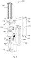
- the working platform 150 descends to a required height above a stencil of the printer (i.e. line L shown in fig. 5 ), realizing positioning of the solder paste tub 700 in the height direction.
- the pressure plate 120 is disposed on the inner side 141 of the movable plate 140 so as to be capable of sliding up and down.
- a lower one-way locking mechanism 144, 134 is provided between the movable plate 140 and the support plate 130.
- the lower one-way locking mechanism 144, 134 defines the lower stopping point of upward and downward movement of the movable plate 140, and locks the movable plate 140 when the movable plate 140 is in the working position, so that the movable plate 140 cannot continue to move downward.
- the positioning action of moving the solder paste tub 700 and the solder paste nozzle 500 to the required height above the stencil, and the solder addition action of distributing solder paste onto the stencil from the solder paste tub nozzle, can be realized using just one drive apparatus 160.
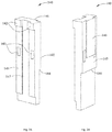
- the upper locking mechanism 142, 122 and the lower one-way locking mechanism 144, 134 are presented in detail below with reference to figs. 2A, 2B , 3A and 3B .
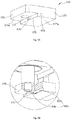
- Figs. 3A and 3B show inside and outside three-dimensional views respectively of the pressure plate 120 of the present application.
- the upper locking mechanism 142, 122 comprises a pulling edge 122 disposed on the pressure plate 120 and a force-bearing protruding edge 142 disposed on the inner side 141 of the movable plate 140; the pulling edge 122 is located below the force-bearing protruding edge 142, and has a part which forms an overlap with the force-bearing protruding edge 142.
- both downward and upward movement of the movable plate 140 relative to the support plate 130 can be controlled by movement of the pressure plate 120.
- the movable plate 140 is locked in the working position thereof by the lower one-way locking mechanism 144, 134, continued downward movement of the pressure plate 120 will cause the pulling edge 122 thereof to separate from the force-bearing protruding edge 142 of the movable plate 140, thereby releasing the movable plate 140.
- the pressure plate 120 can move downward relative to the movable plate 140, to press the solder paste tub 700, and perform a working process of solder addition.
- Fig. 4 shows a sectional view along line A-A in fig. 1A .
- Fig. 4 shows cross sections of the first slider 146, the first slide groove 136, the second slider 127 and the second slide groove 147, and shows the fitting relationships between the second slider 127 of the pressure plate 120 and the second slide groove 147 of the movable plate 140, and between the first slider 146 of the movable plate 140 and the first slide groove 136 of the support plate 130.
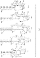
- the automatic solder paste addition apparatus 100 has a parking position in the printer; before starting the working cycle of the automatic solder paste addition apparatus 100, it is necessary to first move the automatic solder paste addition apparatus 100 from the parking position to the starting position requiring solder paste addition on the stencil L, and after completing a solder addition process, it is necessary to move the automatic solder paste addition apparatus 100 from the end position requiring solder paste addition on the stencil L back to the parking position.
- the pressure plate 120 and the movable plate 140 have the following strokes: (i) a stroke of joint downward movement towards the working position of the movable plate 140; (ii) a stroke of relative downward movement after the working position of the movable plate 140 has been reached; (iii) a stroke of relative upward movement after the working process has ended; (iv) a stroke of joint upward movement.
- solder paste is a fluid of high viscosity, hence the solder paste accommodated in the solder paste tub 700 and a housing (710) of the solder paste tub 700 (as shown in fig. 7A ) stick together, and the solder paste has a certain weight.
- the elasticity of the flat spiral spring should be matched to the weight of the solder paste accommodated in the solder paste tub 700. Specifically, the elasticity of the flat spiral spring must not be set too high, in order to prevent the solder paste tub 700 from being pulled off the solder paste nozzle 500, and must not be set too low, in order to avoid a situation where a sufficient pulling force to offset the weight of the solder paste cannot be applied to the solder paste tub 700.
- the flat spiral spring enables the holder 180 to move as the solder paste tub 700 is pressed to move downward.
- the height adjustment apparatus 190 may comprise two flat spiral springs, connected to two ends of the holder 180 respectively.
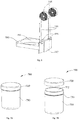
- Figs. 7A and 7B show a three-dimensional view and an exploded view respectively of a solder paste tub of the present application.
- the solder paste tub 700 comprises the housing 710 and a lid 720; the housing 710 has an outlet 712, and the lid 720 covers the outlet 712. Once solder paste has been packed into the housing 710, the lid 720 closes the outlet 712, to seal the solder paste in the housing 710.
Landscapes
- Engineering & Computer Science (AREA)
- Mechanical Engineering (AREA)
- Manufacturing & Machinery (AREA)
- Microelectronics & Electronic Packaging (AREA)
- Electric Connection Of Electric Components To Printed Circuits (AREA)
- Screen Printers (AREA)
Claims (8)
- Appareil d'ajout automatique de pâte à braser (100) pour une imprimante de pâte à braser, comprenant :un appareil d'entraînement (160) ;une tige de poussée (110) entraînée par l'appareil d'entraînement pour déplacer la tige de poussée (110) vers le haut et le bas ;une plaque de pression (120) disposée à une extrémité de la tige de poussée (110), la plaque de pression (120) se déplaçant vers le haut et le bas lorsque la tige de poussée (110) se déplace vers le haut et le bas ;une plaque d'appui (130) fixe par rapport au mouvement de la tige de poussée (110) ;caractérisé en ce que l'appareil comprend en outre :une plaque mobile (140), ayant une position de travail et ayant un côté interne (141) et un côté externe (145), le côté externe (145) de la plaque mobile (140) étant disposé sur la plaque d'appui (130) et étant configuré pour glisser vers le haut et le bas par rapport à la plaque d'appui (130), et la plaque de pression (120) étant disposée sur le côté interne (141) de la plaque mobile (140) et étant configurée pour glisser vers le haut et le bas par rapport à la plaque mobile (140) ;une plate-forme de travail (150) destinée à supporter un tube de pâte à braser (700), la plate-forme de travail (150) étant fixée à la plaque mobile (140), et se déplaçant vers le haut et le bas lorsque la plaque mobile (140) se déplace vers le haut et le bas,dans lequel un mécanisme de verrouillage unidirectionnel inférieur (144, 134) est disposé entre la plaque mobile (140) et la plaque d'appui (130), le mécanisme de verrouillage unidirectionnel inférieur (144, 134) étant configuré pour verrouiller la plaque mobile quand la plaque mobile (140) est dans la position de travail, de telle sorte que la plaque mobile (140) ne peut pas se déplacer vers le bas, le mécanisme de verrouillage unidirectionnel inférieur (144, 134) comprenant un bord saillant de blocage (134) disposé à une extrémité inférieure (131) de la plaque d'appui (130), et un bord saillant bloqué (144) disposé sur le côté externe (145) de la plaque mobile (140), le bord saillant de blocage (134) étant situé sous le bord saillant bloqué (144), et ayant une partie qui forme un chevauchement avec le bord saillant bloqué (144) ;et dans lequel un mécanisme de verrouillage supérieur (142, 122) est disposé entre la plaque mobile (140) et la plaque de pression (120), le mécanisme de verrouillage supérieur (142, 122) étant configuré de telle sorte que la plaque de pression (120) peut se déplacer par rapport à la plaque mobile (140) quand la plaque mobile (140) ne se déplace pas, et peut aussi se déplacer conjointement avec la plaque mobile (140) quand la plaque mobile (140) se déplace, le mécanisme de verrouillage supérieur (142, 122) comprenant un bord de traction (122) disposé sur la plaque de pression (120), et un bord saillant de support de force (142) disposé sur le côté interne (141) de la plaque mobile (140), le bord de traction (122) étant situé sous le bord saillant de support de force (142), et ayant une partie qui forme un chevauchement avec le bord saillant de support de force (142).
- Appareil d'ajout automatique de pâte à braser (100) selon la revendication 1, caractérisé en ce que l'appareil comprend en outre un système de commande, et en ce que le système de commande est configuré pour faire fonctionner l'appareil de telle sorte que la plaque de pression (120) et la plaque mobile (140) aient les courses suivantes :(i) une course de déplacement conjoint vers le bas en direction de la position de travail de la plaque mobile (140) ;(ii) une course de déplacement relatif vers le bas après que la position de travail de la plaque mobile (140) a été atteinte ;(iii) une course de déplacement relatif vers le haut après qu'une opération s'est achevée ;(iv) une course de déplacement conjoint vers le haut,et le mécanisme de verrouillage supérieur (142, 122) est configuré de telle sorte que :(i) dans la course de déplacement conjoint de la plaque de pression (120) et de la plaque mobile (140) vers le bas en direction de la position de travail, le mécanisme de verrouillage supérieur (142, 122) verrouille la plaque mobile (140), de telle sorte que la plaque mobile (140) ne peut pas se déplacer librement vers le bas, mais peut se déplacer vers le bas lorsque la tige de poussée (110) se déplace vers le bas,(ii) quand la plaque mobile (140) se déplace jusqu'à la position de travail et est verrouillée par le mécanisme de verrouillage unidirectionnel inférieur (144, 134), dans la course de déplacement relatif vers le bas de la plaque de pression (120) et de la plaque mobile (140), le mécanisme de verrouillage supérieur (142, 122) libère la plaque mobile (140), de telle sorte que la plaque de pression (120) peut se déplacer vers le bas par rapport à la plaque mobile (140),(iii) quand la plaque mobile (140) est dans la position de travail et est verrouillée par le mécanisme de verrouillage unidirectionnel inférieur (144, 134), et une fois que l'opération s'est achevée, dans la course de déplacement relatif vers le haut de la plaque de pression (120) et de la plaque mobile (140), le mécanisme de verrouillage supérieur (142, 122) libère la plaque mobile (140), de telle sorte que la plaque de pression (120) peut se déplacer vers le haut par rapport à la plaque mobile (140),(iv) dans la course de déplacement conjoint vers le haut de la plaque de pression (120) et de la plaque mobile (140), le mécanisme de verrouillage supérieur (142, 122) verrouille la plaque mobile (140), de telle sorte que la plaque mobile (140) se déplace vers le haut lorsque la tige de poussée (110) se déplace vers le haut.
- Appareil d'ajout automatique de pâte à braser (100) selon la revendication 2, caractérisé en ce que :
dans la course de déplacement relatif vers le bas de la plaque de pression (120) et de la plaque mobile (140), la plaque de pression (120) appuie sur le tube de pâte à braser (700) ; dans la course de déplacement relatif vers le haut de la plaque de pression (120) et de la plaque mobile (140), la plaque de pression (120) s'éloigne du tube de pâte à braser (700). - Appareil d'ajout automatique de pâte à braser (100) selon la revendication 1, caractérisé en ce qu'il comprend en outre :une plaque transversale de montage (170), avec l'appareil d'entraînement (160) fixé à une extrémité supérieure (132) de la plaque d'appui (130) au moyen de la plaque transversale de montage (170),dans lequel la plaque transversale de montage (170) est pourvue d'un trou (172) pour que la tige de poussée (110) s'y étende.
- Appareil d'ajout automatique de pâte à braser (100) selon la revendication 1, caractérisé en ce que :la plaque d'appui (130) a une première rainure de glissement (136) s'étendant entre une extrémité supérieure (132) et une extrémité inférieure (131) de celle-ci ;la plaque mobile (140) a une première glissière (146) sur le côté externe (145) de celle-ci et une deuxième rainure de glissement (147) sur le côté interne (141) de celle-ci ;la plaque de pression (120) a une deuxième glissière (127) ;la première glissière (146) et la première rainure de glissement (136) s'ajustent ensemble, de manière à relier la plaque mobile (140) à la plaque d'appui (130) de telle sorte que la plaque mobile peut glisser vers le haut et le bas ;la deuxième glissière (127) et la deuxième rainure de glissement (147) s'ajustent ensemble, de manière à relier la plaque de pression (120) à la plaque mobile (140) de telle sorte que la plaque de pression peut glisser vers le haut et le bas.
- Appareil d'ajout automatique de pâte à braser (100) selon la revendication 5, caractérisé en ce que :
la première glissière (146), la première rainure de glissement (136), la deuxième glissière (127) et la deuxième rainure de glissement (147) ont toutes des sections transversales trapézoïdales. - Système d'ajout automatique de pâte à braser pour une imprimante de pâte à braser, caractérisé en ce qu'il comprend :l'appareil d'ajout automatique de pâte à braser (100) selon l'une quelconque des revendications 1 à 6 ; etun ensemble tube de pâte à braser (800), comprenant le tube de pâte à braser (700) et une buse de pâte à braser (500) accueillie dans le tube de pâte à braser (700), avec le tube de pâte à braser (700) supporté d'une manière inversée sur la plate-forme de travail (150) de l'appareil d'ajout automatique de pâte à braser (100) au moyen de la buse de pâte à braser (500).
- Système d'ajout automatique de pâte à braser pour une imprimante de pâte à braser selon la revendication 7, caractérisé en ce que :
la plate-forme de travail (150) est pourvue d'un trou débouchant (155), avec la buse de pâte à braser (500) insérée dans le trou débouchant (155), de telle sorte que de la pâte à braser peut s'écouler à travers le trou débouchant (155).
Applications Claiming Priority (3)
| Application Number | Priority Date | Filing Date | Title |
|---|---|---|---|
| CN201720395641.0U CN207266404U (zh) | 2017-04-14 | 2017-04-14 | 用于锡膏印刷机的自动加锡膏装置 |
| CN201710244587.4A CN108738245B (zh) | 2017-04-14 | 2017-04-14 | 用于锡膏印刷机的自动加锡膏装置 |
| PCT/IB2018/000475 WO2018189590A1 (fr) | 2017-04-14 | 2018-04-13 | Appareil d'ajout de pâte à souder automatique pour imprimante à pâte à souder |
Publications (2)
| Publication Number | Publication Date |
|---|---|
| EP3611020A1 EP3611020A1 (fr) | 2020-02-19 |
| EP3611020B1 true EP3611020B1 (fr) | 2021-07-07 |
Family
ID=62816879
Family Applications (1)
| Application Number | Title | Priority Date | Filing Date |
|---|---|---|---|
| EP18737404.6A Active EP3611020B1 (fr) | 2017-04-14 | 2018-04-13 | Appareil d'ajout de pâte à souder automatique pour imprimante à pâte à souder |
Country Status (6)
| Country | Link |
|---|---|
| US (1) | US11167365B2 (fr) |
| EP (1) | EP3611020B1 (fr) |
| JP (1) | JP7127055B2 (fr) |
| KR (1) | KR102376418B1 (fr) |
| TW (1) | TWI755518B (fr) |
| WO (1) | WO2018189590A1 (fr) |
Families Citing this family (5)
| Publication number | Priority date | Publication date | Assignee | Title |
|---|---|---|---|---|
| KR102376418B1 (ko) * | 2017-04-14 | 2022-03-17 | 일리노이즈 툴 워크스 인코포레이티드 | 솔더 페이스트 프린터를 위한 자동 솔더 페이스트 도포 장치 |
| TWI760479B (zh) * | 2017-04-14 | 2022-04-11 | 美商伊利諾工具工程公司 | 用於自動清除殘留錫膏的裝置 |
| JP7029598B2 (ja) * | 2018-04-27 | 2022-03-04 | パナソニックIpマネジメント株式会社 | ペースト供給装置およびスクリーン印刷装置 |
| TWI789552B (zh) * | 2018-11-26 | 2023-01-11 | 美商伊利諾工具工程公司 | 範本印刷機 |
| CN112570847B (zh) * | 2020-11-30 | 2023-10-13 | 深圳市富贵花实业有限公司 | 一种解决无法定量点锡膏且多余锡膏无法回收的装置 |
Family Cites Families (55)
| Publication number | Priority date | Publication date | Assignee | Title |
|---|---|---|---|---|
| US4710399A (en) * | 1986-09-02 | 1987-12-01 | Dennis Richard K | Method and mechanism to deposit solder paste upon substrates |
| DE3727343A1 (de) * | 1987-08-17 | 1989-03-02 | Bosch Gmbh Robert | Verfahren zum dosieren der lotmenge bei einer loetvorrichtung |
| US4942984A (en) * | 1988-11-10 | 1990-07-24 | Scm Metal Products, Inc. | Dripless solder paste dispenser |
| SE465713B (sv) * | 1990-02-12 | 1991-10-21 | Mydata Automation Ab | Anordning foer att utlaegga pastor och lim |
| US5137181A (en) * | 1990-07-18 | 1992-08-11 | Wilhelm A. Keller | Manually operated appliance, in particular for a double dispensing cartridge for two-component substances |
| US6395087B1 (en) | 1994-12-27 | 2002-05-28 | Visteon Global Technologies, Inc. | Method and apparatus for dispensing viscous material |
| US6082289A (en) * | 1995-08-24 | 2000-07-04 | Speedline Technologies, Inc. | Liquid dispensing system with controllably movable cartridge |
| US6267266B1 (en) * | 1995-11-16 | 2001-07-31 | Nordson Corporation | Non-contact liquid material dispenser having a bellows valve assembly and method for ejecting liquid material onto a substrate |
| US5947022A (en) * | 1997-11-07 | 1999-09-07 | Speedline Technologies, Inc. | Apparatus for dispensing material in a printer |
| US6453810B1 (en) * | 1997-11-07 | 2002-09-24 | Speedline Technologies, Inc. | Method and apparatus for dispensing material in a printer |
| JP3058454U (ja) * | 1998-10-14 | 1999-06-18 | 谷電機工業株式会社 | 印刷用ペースト供給装置 |
| WO2000071264A1 (fr) * | 1999-05-21 | 2000-11-30 | Matsushita Electric Industrial Co., Ltd. | Applicateur de matiere visqueuse |
| GB2360252B (en) * | 2000-03-07 | 2002-07-24 | Matsushita Electric Industrial Co Ltd | Screen printing method |
| SE0003647D0 (sv) * | 2000-10-09 | 2000-10-09 | Mydata Automation Ab | Method, apparatus and use |
| US6571701B1 (en) * | 2001-05-04 | 2003-06-03 | Speedline Technologies, Inc. | Stirring mechanism for viscous-material printer and method of printing |
| US20040244612A1 (en) * | 2003-03-28 | 2004-12-09 | Speedline Technologies, Inc. | Method and apparatus for printing viscous material |
| US7249558B2 (en) * | 2004-07-15 | 2007-07-31 | Speedline Technologies, Inc. | Solder paste dispenser for a stencil printer |
| PL2151282T3 (pl) * | 2007-05-18 | 2021-08-02 | Musashi Engineering, Inc. | Sposób i aparat do wyrzucania ciekłego materiału |
| JP5043764B2 (ja) * | 2008-06-30 | 2012-10-10 | 株式会社ジャパンユニックス | レーザー式はんだ付け方法及び装置 |
| US9162249B2 (en) * | 2008-10-01 | 2015-10-20 | Panasonic Intellectual Property Management Co., Ltd. | Paste dispenser for applying paste containing fillers using nozzle with pin and application method using the same |
| JP4764470B2 (ja) * | 2008-11-10 | 2011-09-07 | 株式会社東芝 | 塗布装置 |
| US7845541B1 (en) * | 2009-12-01 | 2010-12-07 | Cheng Uei Precision Industry Co., Ltd. | Soldering apparatus and soldering method |
| JP5408157B2 (ja) * | 2011-03-09 | 2014-02-05 | パナソニック株式会社 | スクリーン印刷装置およびスクリーン印刷方法 |
| US9975206B2 (en) * | 2011-04-08 | 2018-05-22 | Micronic Mydata AB | Composition of solid-containing paste |
| JP5806868B2 (ja) * | 2011-07-11 | 2015-11-10 | 武蔵エンジニアリング株式会社 | 液滴吐出装置および方法 |
| JP5887488B2 (ja) | 2011-12-16 | 2016-03-16 | パナソニックIpマネジメント株式会社 | ペースト供給装置およびスクリーン印刷装置 |
| US8939073B2 (en) * | 2012-02-08 | 2015-01-27 | Illinois Tool Works Inc. | Print head for stencil printer |
| KR20130141926A (ko) * | 2012-06-18 | 2013-12-27 | 삼성전기주식회사 | 솔더 페이스트 토출 장치, 이를 포함한 패터닝 시스템 및 그 제어 방법 |
| US20140093658A1 (en) * | 2012-09-28 | 2014-04-03 | General Electric Company | Methods and systems for joining materials |
| JP2014151507A (ja) | 2013-02-07 | 2014-08-25 | Panasonic Corp | ペースト供給装置、スクリーン印刷機、ペースト供給方法及びスクリーン印刷方法 |
| JP5895133B2 (ja) | 2013-06-12 | 2016-03-30 | パナソニックIpマネジメント株式会社 | ペースト供給装置、スクリーン印刷機、ペースト供給方法及びスクリーン印刷方法 |
| JP5895134B2 (ja) * | 2013-06-12 | 2016-03-30 | パナソニックIpマネジメント株式会社 | ペースト供給装置、スクリーン印刷機、ペースト供給方法及びスクリーン印刷方法 |
| EP3078442B1 (fr) * | 2013-12-05 | 2018-10-24 | FUJI Corporation | Dispositif de fourniture de métal d'apport |
| US9802264B2 (en) * | 2013-12-18 | 2017-10-31 | Fuji Machine Mfg. Co., Ltd. | Solder supply device including a sensor to detect movement of a solder container |
| WO2015128967A1 (fr) * | 2014-02-26 | 2015-09-03 | 富士機械製造株式会社 | Système de distribution de soudure |
| JP6101937B2 (ja) * | 2014-03-17 | 2017-03-29 | パナソニックIpマネジメント株式会社 | ペースト供給装置及びスクリーン印刷装置 |
| JP6194481B2 (ja) * | 2014-03-17 | 2017-09-13 | パナソニックIpマネジメント株式会社 | スクリーン印刷装置及びスクリーン印刷方法 |
| JP6221063B2 (ja) * | 2014-03-17 | 2017-11-01 | パナソニックIpマネジメント株式会社 | スクリーン印刷装置及びスクリーン印刷方法 |
| JP6167336B2 (ja) * | 2014-03-19 | 2017-07-26 | パナソニックIpマネジメント株式会社 | ペースト供給装置、スクリーン印刷装置、ペースト供給方法及びスクリーン印刷方法 |
| JP2016049720A (ja) * | 2014-09-01 | 2016-04-11 | パナソニックIpマネジメント株式会社 | スクリーン印刷装置およびスクリーン印刷方法 |
| JP6452147B2 (ja) * | 2015-01-19 | 2019-01-16 | 武蔵エンジニアリング株式会社 | 液体材料吐出装置 |
| KR101731559B1 (ko) * | 2015-02-06 | 2017-05-04 | 주식회사이에스이 | 솔더 자동 주입기 |
| US10703089B2 (en) * | 2015-04-07 | 2020-07-07 | Illinois Tool Works Inc. | Edge lock assembly for a stencil printer |
| US9370923B1 (en) * | 2015-04-07 | 2016-06-21 | Illinois Tool Works Inc. | Lift tool assembly for stencil printer |
| CN205705695U (zh) * | 2016-05-04 | 2016-11-23 | 依工电子设备(苏州)有限公司 | 具有自清洁功能的加锡膏装置 |
| CN108581118B (zh) * | 2017-03-17 | 2022-01-11 | 泰科电子(上海)有限公司 | 焊膏自动供应系统 |
| WO2018187537A1 (fr) * | 2017-04-06 | 2018-10-11 | Commscope Technologies Llc | Procédés et appareils de distribution de brasure |
| US11173562B2 (en) * | 2017-04-14 | 2021-11-16 | Illinois Tool Works Inc. | Solder paste feeding assembly and method |
| KR102376418B1 (ko) * | 2017-04-14 | 2022-03-17 | 일리노이즈 툴 워크스 인코포레이티드 | 솔더 페이스트 프린터를 위한 자동 솔더 페이스트 도포 장치 |
| TWI759460B (zh) * | 2017-04-14 | 2022-04-01 | 美商伊利諾工具工程公司 | 用於防止錫膏滴落的裝置 |
| TWI760479B (zh) * | 2017-04-14 | 2022-04-11 | 美商伊利諾工具工程公司 | 用於自動清除殘留錫膏的裝置 |
| US20190174633A1 (en) * | 2017-12-05 | 2019-06-06 | Illinois Tool Works Inc. | Material temperature sensor for stencil printer |
| US10933483B2 (en) * | 2017-12-05 | 2021-03-02 | Illinois Tool Works Inc. | IR non-contact temperature sensing in a dispenser |
| US11247286B2 (en) * | 2019-06-13 | 2022-02-15 | Illinois Tool Works Inc. | Paste dispensing transfer system and method for a stencil printer |
| US11318549B2 (en) * | 2019-06-13 | 2022-05-03 | Illinois Tool Works Inc. | Solder paste bead recovery system and method |
-
2018
- 2018-04-13 KR KR1020197033355A patent/KR102376418B1/ko active Active
- 2018-04-13 TW TW107112760A patent/TWI755518B/zh not_active IP Right Cessation
- 2018-04-13 JP JP2019555913A patent/JP7127055B2/ja active Active
- 2018-04-13 WO PCT/IB2018/000475 patent/WO2018189590A1/fr not_active Ceased
- 2018-04-13 EP EP18737404.6A patent/EP3611020B1/fr active Active
- 2018-04-13 US US16/604,459 patent/US11167365B2/en not_active Expired - Fee Related
Also Published As
| Publication number | Publication date |
|---|---|
| JP7127055B2 (ja) | 2022-08-29 |
| EP3611020A1 (fr) | 2020-02-19 |
| JP2020516500A (ja) | 2020-06-11 |
| US20200147711A1 (en) | 2020-05-14 |
| WO2018189590A1 (fr) | 2018-10-18 |
| TWI755518B (zh) | 2022-02-21 |
| US11167365B2 (en) | 2021-11-09 |
| KR20190139261A (ko) | 2019-12-17 |
| KR102376418B1 (ko) | 2022-03-17 |
| TW201840259A (zh) | 2018-11-01 |
Similar Documents
| Publication | Publication Date | Title |
|---|---|---|
| US11173562B2 (en) | Solder paste feeding assembly and method | |
| EP3610974B1 (fr) | Appareil pour dégager automatiquement une pâte de soudure résiduelle, comprenant un canal de gaz dans la plate-forme de travail servant de support à une cuve de pâte à souder | |
| US11167365B2 (en) | Automatic solder paste addition apparatus for solder paste printer | |
| EP3610957B1 (fr) | Appareil pour empêcher l'égouttement de pâte à braser | |
| CN108738246B (zh) | 用于自动清除残留锡膏的装置 | |
| CN108738245B (zh) | 用于锡膏印刷机的自动加锡膏装置 | |
| CN108724920B (zh) | 用于防止锡膏滴落的装置 | |
| JP7670610B2 (ja) | ステンシル印刷機 | |
| CN108738247B (zh) | 一种供锡组件 | |
| CN207266404U (zh) | 用于锡膏印刷机的自动加锡膏装置 | |
| CN207266403U (zh) | 用于自动清除残留锡膏的装置 | |
| CN207266402U (zh) | 一种供锡组件 |
Legal Events
| Date | Code | Title | Description |
|---|---|---|---|
| STAA | Information on the status of an ep patent application or granted ep patent |
Free format text: STATUS: UNKNOWN |
|
| STAA | Information on the status of an ep patent application or granted ep patent |
Free format text: STATUS: THE INTERNATIONAL PUBLICATION HAS BEEN MADE |
|
| PUAI | Public reference made under article 153(3) epc to a published international application that has entered the european phase |
Free format text: ORIGINAL CODE: 0009012 |
|
| STAA | Information on the status of an ep patent application or granted ep patent |
Free format text: STATUS: REQUEST FOR EXAMINATION WAS MADE |
|
| 17P | Request for examination filed |
Effective date: 20191029 |
|
| AK | Designated contracting states |
Kind code of ref document: A1 Designated state(s): AL AT BE BG CH CY CZ DE DK EE ES FI FR GB GR HR HU IE IS IT LI LT LU LV MC MK MT NL NO PL PT RO RS SE SI SK SM TR |
|
| AX | Request for extension of the european patent |
Extension state: BA ME |
|
| DAV | Request for validation of the european patent (deleted) | ||
| DAX | Request for extension of the european patent (deleted) | ||
| GRAP | Despatch of communication of intention to grant a patent |
Free format text: ORIGINAL CODE: EPIDOSNIGR1 |
|
| STAA | Information on the status of an ep patent application or granted ep patent |
Free format text: STATUS: GRANT OF PATENT IS INTENDED |
|
| INTG | Intention to grant announced |
Effective date: 20210202 |
|
| GRAS | Grant fee paid |
Free format text: ORIGINAL CODE: EPIDOSNIGR3 |
|
| GRAA | (expected) grant |
Free format text: ORIGINAL CODE: 0009210 |
|
| STAA | Information on the status of an ep patent application or granted ep patent |
Free format text: STATUS: THE PATENT HAS BEEN GRANTED |
|
| AK | Designated contracting states |
Kind code of ref document: B1 Designated state(s): AL AT BE BG CH CY CZ DE DK EE ES FI FR GB GR HR HU IE IS IT LI LT LU LV MC MK MT NL NO PL PT RO RS SE SI SK SM TR |
|
| REG | Reference to a national code |
Ref country code: GB Ref legal event code: FG4D |
|
| REG | Reference to a national code |
Ref country code: AT Ref legal event code: REF Ref document number: 1408179 Country of ref document: AT Kind code of ref document: T Effective date: 20210715 |
|
| REG | Reference to a national code |
Ref country code: DE Ref legal event code: R096 Ref document number: 602018019775 Country of ref document: DE |
|
| REG | Reference to a national code |
Ref country code: IE Ref legal event code: FG4D |
|
| REG | Reference to a national code |
Ref country code: LT Ref legal event code: MG9D |
|
| REG | Reference to a national code |
Ref country code: NL Ref legal event code: MP Effective date: 20210707 |
|
| REG | Reference to a national code |
Ref country code: AT Ref legal event code: MK05 Ref document number: 1408179 Country of ref document: AT Kind code of ref document: T Effective date: 20210707 |
|
| PG25 | Lapsed in a contracting state [announced via postgrant information from national office to epo] |
Ref country code: SE Free format text: LAPSE BECAUSE OF FAILURE TO SUBMIT A TRANSLATION OF THE DESCRIPTION OR TO PAY THE FEE WITHIN THE PRESCRIBED TIME-LIMIT Effective date: 20210707 Ref country code: RS Free format text: LAPSE BECAUSE OF FAILURE TO SUBMIT A TRANSLATION OF THE DESCRIPTION OR TO PAY THE FEE WITHIN THE PRESCRIBED TIME-LIMIT Effective date: 20210707 Ref country code: ES Free format text: LAPSE BECAUSE OF FAILURE TO SUBMIT A TRANSLATION OF THE DESCRIPTION OR TO PAY THE FEE WITHIN THE PRESCRIBED TIME-LIMIT Effective date: 20210707 Ref country code: FI Free format text: LAPSE BECAUSE OF FAILURE TO SUBMIT A TRANSLATION OF THE DESCRIPTION OR TO PAY THE FEE WITHIN THE PRESCRIBED TIME-LIMIT Effective date: 20210707 Ref country code: HR Free format text: LAPSE BECAUSE OF FAILURE TO SUBMIT A TRANSLATION OF THE DESCRIPTION OR TO PAY THE FEE WITHIN THE PRESCRIBED TIME-LIMIT Effective date: 20210707 Ref country code: NO Free format text: LAPSE BECAUSE OF FAILURE TO SUBMIT A TRANSLATION OF THE DESCRIPTION OR TO PAY THE FEE WITHIN THE PRESCRIBED TIME-LIMIT Effective date: 20211007 Ref country code: NL Free format text: LAPSE BECAUSE OF FAILURE TO SUBMIT A TRANSLATION OF THE DESCRIPTION OR TO PAY THE FEE WITHIN THE PRESCRIBED TIME-LIMIT Effective date: 20210707 Ref country code: PT Free format text: LAPSE BECAUSE OF FAILURE TO SUBMIT A TRANSLATION OF THE DESCRIPTION OR TO PAY THE FEE WITHIN THE PRESCRIBED TIME-LIMIT Effective date: 20211108 Ref country code: LT Free format text: LAPSE BECAUSE OF FAILURE TO SUBMIT A TRANSLATION OF THE DESCRIPTION OR TO PAY THE FEE WITHIN THE PRESCRIBED TIME-LIMIT Effective date: 20210707 Ref country code: BG Free format text: LAPSE BECAUSE OF FAILURE TO SUBMIT A TRANSLATION OF THE DESCRIPTION OR TO PAY THE FEE WITHIN THE PRESCRIBED TIME-LIMIT Effective date: 20211007 Ref country code: AT Free format text: LAPSE BECAUSE OF FAILURE TO SUBMIT A TRANSLATION OF THE DESCRIPTION OR TO PAY THE FEE WITHIN THE PRESCRIBED TIME-LIMIT Effective date: 20210707 |
|
| PG25 | Lapsed in a contracting state [announced via postgrant information from national office to epo] |
Ref country code: PL Free format text: LAPSE BECAUSE OF FAILURE TO SUBMIT A TRANSLATION OF THE DESCRIPTION OR TO PAY THE FEE WITHIN THE PRESCRIBED TIME-LIMIT Effective date: 20210707 Ref country code: LV Free format text: LAPSE BECAUSE OF FAILURE TO SUBMIT A TRANSLATION OF THE DESCRIPTION OR TO PAY THE FEE WITHIN THE PRESCRIBED TIME-LIMIT Effective date: 20210707 Ref country code: GR Free format text: LAPSE BECAUSE OF FAILURE TO SUBMIT A TRANSLATION OF THE DESCRIPTION OR TO PAY THE FEE WITHIN THE PRESCRIBED TIME-LIMIT Effective date: 20211008 |
|
| REG | Reference to a national code |
Ref country code: DE Ref legal event code: R097 Ref document number: 602018019775 Country of ref document: DE |
|
| PG25 | Lapsed in a contracting state [announced via postgrant information from national office to epo] |
Ref country code: DK Free format text: LAPSE BECAUSE OF FAILURE TO SUBMIT A TRANSLATION OF THE DESCRIPTION OR TO PAY THE FEE WITHIN THE PRESCRIBED TIME-LIMIT Effective date: 20210707 |
|
| PLBE | No opposition filed within time limit |
Free format text: ORIGINAL CODE: 0009261 |
|
| STAA | Information on the status of an ep patent application or granted ep patent |
Free format text: STATUS: NO OPPOSITION FILED WITHIN TIME LIMIT |
|
| PG25 | Lapsed in a contracting state [announced via postgrant information from national office to epo] |
Ref country code: SM Free format text: LAPSE BECAUSE OF FAILURE TO SUBMIT A TRANSLATION OF THE DESCRIPTION OR TO PAY THE FEE WITHIN THE PRESCRIBED TIME-LIMIT Effective date: 20210707 Ref country code: SK Free format text: LAPSE BECAUSE OF FAILURE TO SUBMIT A TRANSLATION OF THE DESCRIPTION OR TO PAY THE FEE WITHIN THE PRESCRIBED TIME-LIMIT Effective date: 20210707 Ref country code: RO Free format text: LAPSE BECAUSE OF FAILURE TO SUBMIT A TRANSLATION OF THE DESCRIPTION OR TO PAY THE FEE WITHIN THE PRESCRIBED TIME-LIMIT Effective date: 20210707 Ref country code: EE Free format text: LAPSE BECAUSE OF FAILURE TO SUBMIT A TRANSLATION OF THE DESCRIPTION OR TO PAY THE FEE WITHIN THE PRESCRIBED TIME-LIMIT Effective date: 20210707 Ref country code: CZ Free format text: LAPSE BECAUSE OF FAILURE TO SUBMIT A TRANSLATION OF THE DESCRIPTION OR TO PAY THE FEE WITHIN THE PRESCRIBED TIME-LIMIT Effective date: 20210707 Ref country code: AL Free format text: LAPSE BECAUSE OF FAILURE TO SUBMIT A TRANSLATION OF THE DESCRIPTION OR TO PAY THE FEE WITHIN THE PRESCRIBED TIME-LIMIT Effective date: 20210707 |
|
| 26N | No opposition filed |
Effective date: 20220408 |
|
| PG25 | Lapsed in a contracting state [announced via postgrant information from national office to epo] |
Ref country code: IT Free format text: LAPSE BECAUSE OF FAILURE TO SUBMIT A TRANSLATION OF THE DESCRIPTION OR TO PAY THE FEE WITHIN THE PRESCRIBED TIME-LIMIT Effective date: 20210707 |
|
| REG | Reference to a national code |
Ref country code: CH Ref legal event code: PL |
|
| GBPC | Gb: european patent ceased through non-payment of renewal fee |
Effective date: 20220413 |
|
| REG | Reference to a national code |
Ref country code: BE Ref legal event code: MM Effective date: 20220430 |
|
| PG25 | Lapsed in a contracting state [announced via postgrant information from national office to epo] |
Ref country code: MC Free format text: LAPSE BECAUSE OF FAILURE TO SUBMIT A TRANSLATION OF THE DESCRIPTION OR TO PAY THE FEE WITHIN THE PRESCRIBED TIME-LIMIT Effective date: 20210707 Ref country code: LU Free format text: LAPSE BECAUSE OF NON-PAYMENT OF DUE FEES Effective date: 20220413 Ref country code: LI Free format text: LAPSE BECAUSE OF NON-PAYMENT OF DUE FEES Effective date: 20220430 Ref country code: GB Free format text: LAPSE BECAUSE OF NON-PAYMENT OF DUE FEES Effective date: 20220413 Ref country code: CH Free format text: LAPSE BECAUSE OF NON-PAYMENT OF DUE FEES Effective date: 20220430 Ref country code: FR Free format text: LAPSE BECAUSE OF NON-PAYMENT OF DUE FEES Effective date: 20220430 |
|
| PG25 | Lapsed in a contracting state [announced via postgrant information from national office to epo] |
Ref country code: BE Free format text: LAPSE BECAUSE OF NON-PAYMENT OF DUE FEES Effective date: 20220430 |
|
| PG25 | Lapsed in a contracting state [announced via postgrant information from national office to epo] |
Ref country code: IE Free format text: LAPSE BECAUSE OF NON-PAYMENT OF DUE FEES Effective date: 20220413 |
|
| P01 | Opt-out of the competence of the unified patent court (upc) registered |
Effective date: 20230606 |
|
| PG25 | Lapsed in a contracting state [announced via postgrant information from national office to epo] |
Ref country code: MK Free format text: LAPSE BECAUSE OF FAILURE TO SUBMIT A TRANSLATION OF THE DESCRIPTION OR TO PAY THE FEE WITHIN THE PRESCRIBED TIME-LIMIT Effective date: 20210707 Ref country code: CY Free format text: LAPSE BECAUSE OF FAILURE TO SUBMIT A TRANSLATION OF THE DESCRIPTION OR TO PAY THE FEE WITHIN THE PRESCRIBED TIME-LIMIT Effective date: 20210707 |
|
| PG25 | Lapsed in a contracting state [announced via postgrant information from national office to epo] |
Ref country code: HU Free format text: LAPSE BECAUSE OF FAILURE TO SUBMIT A TRANSLATION OF THE DESCRIPTION OR TO PAY THE FEE WITHIN THE PRESCRIBED TIME-LIMIT; INVALID AB INITIO Effective date: 20180413 |
|
| PG25 | Lapsed in a contracting state [announced via postgrant information from national office to epo] |
Ref country code: MT Free format text: LAPSE BECAUSE OF FAILURE TO SUBMIT A TRANSLATION OF THE DESCRIPTION OR TO PAY THE FEE WITHIN THE PRESCRIBED TIME-LIMIT Effective date: 20210707 |
|
| PGFP | Annual fee paid to national office [announced via postgrant information from national office to epo] |
Ref country code: DE Payment date: 20250429 Year of fee payment: 8 |
|
| PG25 | Lapsed in a contracting state [announced via postgrant information from national office to epo] |
Ref country code: TR Free format text: LAPSE BECAUSE OF FAILURE TO SUBMIT A TRANSLATION OF THE DESCRIPTION OR TO PAY THE FEE WITHIN THE PRESCRIBED TIME-LIMIT Effective date: 20210707 |