EP3611079A1 - Hilfsrahmen für kraftfahrzeuge - Google Patents
Hilfsrahmen für kraftfahrzeuge Download PDFInfo
- Publication number
- EP3611079A1 EP3611079A1 EP18188643.3A EP18188643A EP3611079A1 EP 3611079 A1 EP3611079 A1 EP 3611079A1 EP 18188643 A EP18188643 A EP 18188643A EP 3611079 A1 EP3611079 A1 EP 3611079A1
- Authority
- EP
- European Patent Office
- Prior art keywords
- tower
- shaped connecting
- shell
- lower shell
- welded
- Prior art date
- Legal status (The legal status is an assumption and is not a legal conclusion. Google has not performed a legal analysis and makes no representation as to the accuracy of the status listed.)
- Granted
Links
Images


Classifications
-
- B—PERFORMING OPERATIONS; TRANSPORTING
- B62—LAND VEHICLES FOR TRAVELLING OTHERWISE THAN ON RAILS
- B62D—MOTOR VEHICLES; TRAILERS
- B62D21/00—Understructures, i.e. chassis frame on which a vehicle body may be mounted
- B62D21/11—Understructures, i.e. chassis frame on which a vehicle body may be mounted with resilient means for suspension, e.g. of wheels or engine; sub-frames for mounting engine or suspensions
Definitions
- the invention relates to a subframe for a motor vehicle, with a lower shell, an upper shell and at least two spaced apart, tower-shaped connecting members projecting upward from the upper side of the upper shell, the lower shell, the upper shell and the tower-shaped connecting elements being made of sheet metal and welded to one another , and wherein the respective tower-shaped connecting member extends through a recess in the upper shell.
- Auxiliary frames for motor vehicles also referred to as axle carriers
- axle carriers are known in various designs. They should be as light as possible with high strength and rigidity and usually have bearing mounts for wheel guide elements and other units in order to enable the installation of complete front or rear axle modules with drive units as a preassembly unit.
- the subframe In order to connect such a subframe to a vehicle body, the subframe has connection sections which, in some known subframes, are tower-shaped and can therefore also be referred to as tower-shaped connecting members or as tower sections or connecting columns.
- the subframe for a motor vehicle, which is mounted on a floor portion of the engine compartment.
- the subframe is composed of right and left frame sections, a front frame section connecting the two right and left frame sections, and two tower-shaped connecting members.
- the right and left frame sections represent right and left connection sections for a lower right wishbone and a lower left wishbone of a front wheel suspension.
- the two tower-shaped connecting links are essentially vertical on the right and left frame sections.
- Each of the The two tower-shaped connecting links comprise a substantially vertically extending rod section formed from a sheet metal shell and an upper tower section which is positioned on an upper section of the rod section and which represents a connecting section of an upper wishbone of the front wheel suspension.
- the subframe is constructed from sheet metal shells and in particular comprises a lower and an upper shell.
- the respective tower-shaped connecting member is received in a cut-out section of the upper shell and in a cut-out section of the lower shell and protrudes downward somewhat beyond the underside of the lower shell.
- a stabilizer is provided in front of each of the two tower-shaped connecting members, which is supported by a support base which is connected to the upper tower section and the vertical rod section of the respective tower-shaped connecting member.
- This known subframe construction in which the tower-shaped connecting member penetrates both the upper shell and the lower shell, is characterized by a high rigidity of the tower-shaped connecting member and thus by a good handlebar connection.
- crash tests have shown that with such a subframe, viewed in the direction of travel, problems regarding the strength of the subframe occur behind the tower-shaped connecting member.
- the present invention has for its object to provide a subframe of the type mentioned, which has a relatively low weight, a high level of rigidity for its connection to a vehicle body and the connection of chassis links, and an improved strength for an improved crash behavior (impact Behavior).
- the invention provides that the respective tower-shaped connecting member sits on the lower shell and is welded to the lower shell at one or more seating points.
- An advantageous embodiment of the subframe according to the invention is characterized in that the lower shell has an upwardly bent edge section, a lower edge section of the tower-shaped connecting member being welded to the upwardly bent edge section of the lower shell.
- the upwardly bent edge section of the lower shell can also be referred to as a flange and is angled or folded relative to a plate-shaped bottom or base section of the lower shell.
- this embodiment has shown a particularly good crash behavior of the subframe according to the invention, the weight of the subframe remaining essentially unchanged or at the same time being able to be reduced.
- the lower edge section of the tower-shaped connecting member is welded to the edge section of the lower shell along an essentially horizontal and / or substantially straight joint.
- the lower edge section of the tower-shaped connecting member is butt-welded to the upwardly bent edge section of the lower shell.
- a further advantageous embodiment of the subframe according to the invention provides that a second lower edge section of the tower-shaped connecting member adjoins the lower edge section of the tower-shaped connecting member, which is welded to the upwardly bent edge section of the lower shell, which is relative to the one with the bent upward member Edge section of the lower shell welded edge section angled and arranged in a cavity which is delimited by the lower shell and the upper shell.
- This configuration enables a more uniform and therefore more favorable introduction of force or load from a suspension arm, in particular a lower wishbone, into a welded connection between the tower-shaped connecting member and the lower shell of the subframe.
- the tower-shaped connecting member has a bent flange at its end facing the lower shell, which flange is welded to the inside of the lower shell.
- the flange can be produced in a simple manner by reshaping a sheet metal section from which the tower-shaped connecting member is or is formed. The flange enables a relatively extensive and thus stress-reduced connection of the tower-shaped connecting member to the lower shell of the subframe.
- a further advantageous embodiment of the subframe according to the invention provides in this context that the lower shell has a recess in the region of the flange, the flange being welded to at least one edge section of the lower shell defined by the recess.
- This configuration is not only advantageous in terms of production engineering, since it offers good accessibility to the flange to be welded to the lower shell. It is also advantageous with regard to a reduction in the weight of the subframe, since the sheet metal section which has been eliminated due to the recess reduces the weight of the lower shell and thus the weight of the subframe.
- the peripheral edge of the recess provides a relatively long joining edge for the formation of one or more weld seams.
- the flange is preferably integrally connected to the lower shell by an essentially circumferential weld seam on the circumferential edge of the recess.
- the weld seam or weld seams extend, for example, over at least 75%, preferably at least 90%, particularly preferably over at least 95% of the edge length of the recess.
- a further embodiment of the invention is characterized in that the tower-shaped connecting member has a bearing eye for the articulated connection of a chassis link, the bearing eye being arranged between an upper side of the upper shell and the lower side of the lower shell.
- the bearing eye is preferably designed in the form of a socket having an internal thread, which is non-positively or materially connected, for example welded, to the tower-shaped connecting member.
- This preferred embodiment contributes to reducing the weight of the subframe, since in this case the tower-shaped connecting member can be made of relatively thin sheet steel, which itself does not have to have a thread for the articulated connection of the suspension arm; the thread is rather provided by the socket connected to the steel sheet of the tower-shaped connecting member.
- the tower-shaped connecting member is composed of a plurality of sheet metal shells, one of its sheet metal shells having the flange and / or the bearing eye.
- This configuration simplifies the implementation of a complex body shape of the tower-shaped connecting member.
- this configuration offers the possibility of closing the sheet metal shells from sheet metal, in particular sheet steel of different sheet thickness and / or material quality finished.
- the tower-shaped connecting link can be designed to be load-bearing with low weight in the sense of the tailored blank technique.
- a reinforcing plate is arranged in the cavity delimited by the lower shell and the upper shell, which is welded to the tower-shaped connecting element, the upper shell and the lower shell.
- the reinforcement plate improves the rigidity and the crash behavior of the subframe and thus also enables a reduction in the weight of the subframe.
- a further embodiment of the invention also provides that the reinforcing plate has a bent flange at its end facing the lower shell, which flange is welded to the inside of the lower shell.
- the lower shell has a recess in the region of the flange, the flange of the reinforcing plate being welded to an edge section of the lower shell defined by the recess.
- the flange of the reinforcement plate can be produced in a simple manner by reshaping the reinforcement plate.
- the flange of the reinforcement plate also enables a relatively extensive and thus stress-reduced connection of the tower-shaped connecting member to the lower shell of the subframe.
- the recess in the lower shell assigned to the flange of the reinforcing plate offers, in particular, good accessibility to the flange to be welded to the lower shell.
- a further advantageous embodiment consists in that the second lower edge section is defined by one leg of the tower-shaped connecting member, this leg being welded to the reinforcing plate.
- This configuration has shown excellent results in tests with regard to the optimization of the crash behavior of the subframe. This configuration enables a particularly favorable one Achieve force transmission or load absorption from a lower suspension arm into a welded connection between the tower-shaped connecting element and the lower shell of the subframe.
- the above-mentioned flange bent on the tower-shaped connecting member and the flange bent on the reinforcing plate are preferably directed towards one another; the two flanges are therefore preferably facing each other.
- a further advantageous embodiment of the subframe according to the invention is characterized in that the tower-shaped connecting member is provided at its upper end facing away from the lower shell with a separately manufactured sheet metal shell, the sheet metal shell having a connecting section for receiving a bearing bush or being provided with a bearing bush.
- the separately manufactured sheet metal shell enables the bearing bush to be optimally connected to the tower-shaped connecting element in a manner that is favorable in terms of production technology.
- the connection of the bearing bush can be realized in a material-saving manner.
- the sheet thickness and / or the strength properties of the separately manufactured sheet metal shell relative to the sheet metal of the tower-shaped connecting member can be selected to suit the load in order to reduce the weight of the subframe.
- the separately manufactured sheet metal shell supporting the bearing bush has at least two legs, one of the legs being welded to a first sheet metal shell of the tower-shaped connecting member, while the second leg is welded to a second sheet metal shell of the tower-shaped connecting member.
- an inventive subframe for a motor vehicle is shown in sections and in different views.
- the subframe has bearings for chassis handlebars to enable the installation of a front or rear axle module as a pre-assembly unit.
- the subframe is composed of three-dimensionally shaped metal sheets that work together are welded.
- the three-dimensionally shaped metal sheets include, among other things, a lower shell 1 and an upper shell 2.
- the auxiliary frame has at least two spaced apart tower-shaped connecting members 3 which protrude upward from the upper side of the upper shell 2.
- the sections of the subframe shown in the drawing only show one of two tower-shaped connecting members 3.
- the two tower-shaped connecting members 3 are essentially mirror images of one another.
- the respective tower-shaped connecting member 3 is welded to the lower shell 1 and the upper shell 2. It extends through a recess 2.1 of the upper shell 2 to the lower shell 1 and is seated on the lower shell 1, where it is welded to the lower shell 1 at at least one seat point, preferably at least two seat points 1.1, 1.2.
- the lower shell 1 has an edge section 1.3 bent upwards relative to a plate-shaped base section or base section of the lower shell, which is welded to a lower edge section 3.1 of the tower-shaped connecting element 3.
- the lower edge section 3.1 of the tower-shaped connecting member 3 is welded to the edge section 1.3 of the lower shell 1 along an essentially straight or horizontal joint 4.
- the joint 4 is designed as an overlap joint or preferably as a butt joint.
- the tower-shaped connecting member 3 has at its end facing the lower shell 1 an angled flange 3.3 which is welded to the inside of the lower shell 1 (cf. Fig. 3 ).
- the lower shell 1 is provided with a recess 1.4 in the region of the flange 3.3, the flange 3.3 being partially welded to at least one edge section 1.5 of the lower shell 1 defined by the recess 1.4.
- the recess 1.4 is designed, for example, in such a way that it has at least two substantially straight edge sections 1.5 which run obliquely to one another.
- the recess 1.4 has an essentially triangular shape with rounded corners.
- the weld connection of the flange 3.3 with the edge defined by the recess 1.4 is preferably designed as a circumferential fillet weld.
- a second lower edge section 3.2 adjoins the lower edge section 3.1 of the tower-shaped connecting member 3 in one piece, which is angled relative to the edge section 3.1 and is arranged in a cavity which is delimited by the lower shell 1 and the upper shell 2.
- the edge section 3.2 is defined by an angled leg 3.5 of the tower-shaped connecting member 3.
- a reinforcing plate 6 is arranged in the cavity delimited by the lower shell 1 and the upper shell 2, which is welded to the leg 3.5 of the tower-shaped connecting element 3, the upper shell 2 and the lower shell 1.
- the reinforcement plate 6 has at its end facing the lower shell 1 a flange 6.1 formed by folding, which is welded to the inside of the lower shell 1.
- the lower shell 1 has a recess 1.7 in the region of the flange 6.1, the flange 6.1 of the reinforcing plate 6 being welded to an edge section 1.8 of the lower shell 1 defined by the recess 1.7.
- the recess 1.7 assigned to the flange 6.1 of the reinforcing plate 6 is slit-shaped.
- the recess 1.7 has mutually parallel edge sections which merge into one another in semicircular ends.
- the flange 3.3 formed on the tower-shaped connecting member 3 and the flange 6.1 formed on the reinforcing plate 6 are directed towards one another, ie they preferably face one another.
- the tower-shaped connecting member 3 is provided with a separately manufactured sheet metal shell 7 which has a connecting section for receiving a bearing bush 8.
- the sheet metal shell 7 has two legs 7.1, 7.2, one of the legs 7.1 being welded to a first sheet metal shell 3b and the second leg 7.2 to a second sheet metal shell 3a of the tower-shaped connecting member 3.
- the connecting section for receiving a bearing bush 8 is formed on a plate-shaped central web 7.3 of the sheet metal shell 7.
- a semicircular indentation 7.4 is cut out in the central web 7.3, into which the bearing bush 8 is inserted in a form-fitting manner and welded to the central web 7.3.
- the various three-dimensionally shaped metal sheets from which the subframe according to the invention is composed are preferably made of sheet steel.
- the lower shell 1 and the upper shell 2 can be made of sheet metal or sheet steel of different sheet thickness and / or material quality, in particular different tensile strength.
- the sheet metal shells 3a, 3b of the tower-shaped connecting member 3, the reinforcing sheet 6 and the sheet metal shell 7 are made from sheet steel of different sheet thickness and / or material quality, in particular different tensile strength.
Landscapes
- Engineering & Computer Science (AREA)
- Chemical & Material Sciences (AREA)
- Combustion & Propulsion (AREA)
- Transportation (AREA)
- Mechanical Engineering (AREA)
- Body Structure For Vehicles (AREA)
Abstract
Description
- Die Erfindung betrifft einen Hilfsrahmen für ein Kraftfahrzeug, mit einer Unterschale, einer Oberschale und mindestens zwei voneinander beabstandeten, gegenüber der Oberseite der Oberschale nach oben vorstehenden, turmförmigen Anbindungsgliedern, wobei die Unterschale, die Oberschale und die turmförmigen Anbindungsglieder aus Metallblech gefertigt und miteinander verschweißt sind, und wobei sich das jeweilige turmförmige Anbindungsglied durch eine Ausnehmung der Oberschale erstreckt.
- Hilfsrahmen für Kraftfahrzeuge, auch als Achsträger bezeichnet, sind in vielfältigen Ausführungen bekannt. Sie sollen bei hoher Festigkeit und Steifigkeit möglichst leicht sein und weisen üblicherweise Lageraufnahmen für Radführungselemente und andere Aggregate auf, um als Vormontageeinheit den Einbau kompletter Vorder- oder Hinterachsmodule mit Antriebseinheiten zu ermöglichen. Zur Anbindung eines solchen Hilfsrahmen an eine Fahrzeugkarosserie weist dieser Anbindungsabschnitte auf, die bei einigen bekannten Hilfsrahmen turmförmig ausgebildet sind und daher auch als turmförmige Anbindungsglieder oder als Turmabschnitte oder Anbindungssäulen bezeichnet werden können.
- In der
DE 10 2014 013 908 A1 ist ein Hilfsrahmen für ein Kraftfahrzeug beschrieben, der an einem Bodenabschnitt des Motorraums montiert wird. Der Hilfsrahmen ist aus rechten und linken Rahmenabschnitten einem vorderenRahmenabschnitt, der die beiden rechten und linken Rahmenabschnitte miteinander verbindet, und zwei turmförmigen Anbindungsgliedern zusammengesetzt. Die rechten und linken Rahmenabschnitte stellen dabei rechte und linke Anbindungsabschnitte für einen rechten unteren Querlenker und einen linken unteren Querlenker einer Vorderradaufhängung dar. Die beiden turmförmigen Anbindungsglieder stehen im Wesentlichen vertikal an den rechten und linken Rahmenabschnitten. Jedes der beiden turmförmigen Anbindungsglieder umfasst einen sich im Wesentlichen vertikal erstreckenden, aus einer Blechschale gebildeten Stangenabschnitt und einen oberen Turmabschnitt, welcher an einem oberen Abschnitt des Stangenabschnitts positioniert istund einen Anbindungsabschnitt eines oberen Querlenkers der Vorderradaufhängung darstellt. Der Hilfsrahmen ist aus Blechschalen aufgebaut und umfasst insbesondere eine Unter- und eine Oberschale. Das jeweilige turmförmige Anbindungsglied ist dabei in einem Ausschnittabschnitt der Oberschale und in einem Ausschnittabschnitt der Unterschale aufgenommen und steht etwas über die Unterseite der Unterschale nach unten vor. Vor den beiden turmförmigen Anbindungsgliedern ist jeweils ein Stabilisator vorgesehen, der durch einen Abstützsockel, der mit dem oberen Turmabschnitt sowie dem vertikalen Stangenabschnitt des jeweiligen turmförmigen Anbindungsgliedes verbunden ist, abgestützt wird. Diese bekannte Hilfsrahmenkonstruktion, bei welcher das turmförmige Anbindungsglied sowohl die Oberschale als auch die Unterschale durchdringt, zeichnet sich durch eine hohe Steifigkeit des turmförmigen Anbindungsgliedes und damit durch eine gute Lenkeranbindung aus. Crash-Tests haben jedoch ergeben, dass bei einem derartigen Hilfsrahmen, in Fahrtrichtung gesehen, hinter dem turmförmigen Anbindungsglied Probleme hinsichtlich der Festigkeit des Hilfsrahmens auftreten. - Der vorliegenden Erfindung liegt die Aufgabe zugrunde, einen Hilfsrahmen der eingangs genannten Art zu schaffen, der bei relativ geringem Gewicht eine hohe Steifigkeit für seine Anbindung an eine Fahrzeugkarosserie und die Anbindung von Fahrwerkslenkern aufweist sowie eine verbesserte Festigkeit für ein verbessertes Crash-Verhalten (Aufprall-Verhalten) bietet.
- Gelöst wird diese Aufgabe durch einen Hilfsrahmen mit den in Anspruch 1 angegebenen Merkmalen. Bevorzugte und vorteilhafte Ausgestaltungen des erfindungsgemäßen Hilfsrahmens sind Gegenstand der auf Anspruch 1 rückbezogenen Unteransprüche.
- Die Erfindung sieht bei einem Hilfsrahmen der eingangs genannten Art vor, dass das jeweilige turmförmige Anbindungsglied auf der Unterschale aufsitzt und an einer oder mehreren Aufsitzstellen mit der Unterschale verschweißt ist. Hierdurch lassen sich sowohl eine optimierte Steifigkeit für die Anbindung des Hilfsrahmens an eine Fahrzeugkarosserie und die Anbindung von Fahrwerkslenkern an dem Hilfsrahmen als auch eine optimierte Festigkeit des Hilfsrahmens hinter den turmförmigen Anbindungsgliedern für ein verbessertes Crash-Verhalten des Hilfsrahmens erzielen, wobei das Gewicht des Hilfsrahmens weitgehend konstant gehalten oder sogar reduziert werden kann.
- Eine vorteilhafte Ausgestaltung des erfindungsgemäßen Hilfsrahmens ist dadurch gekennzeichnet, dass die Unterschale einen nach oben gebogenen Randabschnitt aufweist, wobei ein unterer Kantenabschnitt des turmförmigen Anbindungsgliedes mit dem nach oben gebogenen Randabschnitt der Unterschale verschweißt ist. Der nach oben gebogene Randabschnitt der Unterschale kann auch als Flansch bezeichnet werden und ist relativ zu einem plattenförmigen Boden- oder Grundabschnitt der Unterschale abgewinkelt bzw. abgekantet. Diese Ausgestaltung hat in Versuchen ein besonders gutes Crash-Verhalten des erfindungsgemäßen Hilfsrahmens gezeigt, wobei das Gewicht des Hilfsrahmens im Wesentlichen unverändert blieb bzw. zugleich verringert werden konnte. Insbesondere in fertigungstechnischer Hinsicht ist es dabei günstig, wenn gemäß einer weiteren Ausgestaltung der Erfindung der untere Kantenabschnitt des turmförmigen Anbindungsgliedes mit dem Randabschnitt der Unterschale entlang eines im Wesentlichen horizontal und/oder im Wesentlichen gerade verlaufenden Fügestoßes verschweißt ist.
- Des Weiteren ist es hinsichtlich der Reduzierung des Gewichts des Hilfsrahmens sowie der Optimierung seines Crash-Verhaltens vorteilhaft, wenn gemäß einer weiteren Ausgestaltung der Erfindung der untere Kantenabschnitt des turmförmigen Anbindungsgliedes mit dem nach oben gebogenen Randabschnitt der Unterschale im Stumpfstoß verschweißt ist.
- Eine weitere vorteilhafte Ausgestaltung des erfindungsgemäßen Hilfsrahmens sieht vor, dass sich an den unteren Kantenabschnitt des turmförmigen Anbindungsgliedes, welcher mit dem nach oben gebogenen Randabschnitt der Unterschale verschweißt ist, ein zweiter unterer Kantenabschnitt des turmförmigen Anbindungsgliedes anschließt, der relativ zu dem mit dem nach oben gebogenen Randabschnitt der Unterschale verschweißten Kantenabschnitt abgewinkelt und in einem Hohlraum, welcher durch die Unterschale und die Oberschale begrenzt ist, angeordnet ist. Durch diese Ausgestaltung lässt sich eine gleichmäßigere und damit günstigere Krafteinleitung bzw. Lastaufnahme von einem Fahrwerkslenker, insbesondere einem unteren Querlenker, in eine Schweißverbindung zwischen dem turmförmigen Anbindungsglied und der Unterschale des Hilfsrahmens erzielen. Hohe mechanische Spannungen, die bei hoher Belastung des unteren Fahrwerkslenkers, beispielsweise bei einem Aufprall (Crash) des Kraftfahrzeugs auftreten, können so von einem relativ großen Bereich des Hilfsrahmens, insbesondere einem relativ großen Bereich der Unterschale, besser aufgenommen werden.
- Nach einer weiteren vorteilhaften Ausgestaltung der Erfindung weist das turmförmige Anbindungsglied an seinem der Unterschale zugewandten Ende einen abgekanteten Flansch auf, der mit der Innenseite der Unterschale verschweißt ist. Der Flansch lässt sich fertigungstechnisch auf einfache Weise durch Umformen eines Blechabschnitts, aus welchem das turmförmige Anbindungsglied gebildet wird bzw. ist, herstellen. Der Flansch ermöglicht eine relativ ausgedehnte und damit spannungsreduzierte Anbindung des turmförmigen Anbindungsgliedes an der Unterschale des Hilfsrahmens.
- Eine weitere vorteilhafte Ausgestaltung des erfindungsgemäßen Hilfsrahmens sieht in diesem Zusammenhang vor, dass die Unterschale im Bereich des Flansches eine Ausnehmung aufweist, wobei der Flansch zumindest mit einem durch die Ausnehmung definierten Kantenabschnitt der Unterschale verschweißt ist. Diese Ausgestaltung ist nicht nur in fertigungstechnischer Hinsicht von Vorteil, indem sie eine gute Zugänglichkeit zu dem an die Unterschale anzuschweißenden Flansch bietet. Sie ist zudem auch hinsichtlich einer Reduzierung des Gewichts des Hilfsrahmens günstig, da der aufgrund der Ausnehmung weggefallene Blechabschnitt das Gewicht der Unterschale und damit das Gewicht des Hilfsrahmens reduziert. Des Weiteren stellt die umlaufende Kante der Ausnehmung eine relativ lange Fügekante für die Ausbildung einer oder mehrerer Schweißnähte bereit. Vorzugsweise ist der Flansch durch eine im Wesentlichen umlaufende Schweißnaht an der umlaufenden Kante der Ausnehmung mit der Unterschale stoffschlüssig verbunden. Die Schweißnaht bzw. Schweißnähte erstrecken sich dabei beispielsweise über mindestens 75%, vorzugsweise mindestens 90%, besonders bevorzugt über mindestens 95% der Kantenlänge der Ausnehmung.
- Eine weitere Ausgestaltung der Erfindung ist dadurch gekennzeichnet, dass das turmförmige Anbindungsglied ein Lagerauge zur gelenkigen Anbindung eines Fahrwerklenkers aufweist, wobei das Lagerauge zwischen einer Oberseite der Oberschale und der Unterseite der Unterschale angeordnet ist. Das Lagerauge ist dabei vorzugsweise in Form einer ein Innengewinde aufweisenden Buchse ausgeführt, die mit dem turmförmigen Anbindungsglied kraftschlüssig oder stoffschlüssig verbunden, beispielsweise verschweißt ist. Diese bevorzugte Ausgestaltung trägt zur Gewichtsreduzierung des Hilfsrahmens bei, da das turmförmige Anbindungsglied in diesem Fall aus relativ dünnem Stahlblech gefertigt werden kann, welches zur gelenkigen Anbindung des Fahrwerkslenkers selbst kein Gewinde aufweisen muss; das Gewinde wird vielmehr durch die mit dem Stahlblech des turmförmigen Anbindungsgliedes verbundene Buchse bereitgestellt.
- Eine weitere bevorzugte Ausgestaltung des erfindungsgemäßen Hilfsrahmens sieht vor, dass das turmförmige Anbindungsglied aus mehreren Metallblechschalen zusammengesetzt ist, wobei eine seiner Metallblechschalen den Flansch und/oder das Lagerauge aufweist. Diese Ausgestaltung vereinfacht die Verwirklichung einer komplexen Körperform des turmförmigen Anbindungsgliedes. Ferner bietet diese Ausgestaltung die Möglichkeit, die Metallblechschalen aus Metallblechen, insbesondere Stahlblechen unterschiedlicher Blechdicke und/oder Werkstoffgüte zu fertigen. Somit kann das turmförmige Anbindungsglied bei geringem Gewicht im Sinne der Tailored-Blank-Technik belastungsgerecht ausgeführt werden.
- Nach einer weiteren vorteilhaften Ausgestaltung der Erfindung ist in dem durch die Unterschale und die Oberschale begrenzten Hohlraum ein Verstärkungsblech angeordnet, welches mit dem turmförmigen Anbindungsglied, der Oberschale sowie der Unterschale verschweißt ist. Das Verstärkungsblech verbessert die Steifigkeit und das Crash-Verhalten des Hilfsrahmens und ermöglicht damit auch eine Reduzierung des Gewichts des Hilfsrahmens. In diesem Zusammenhang sieht eine weitere Ausgestaltung der Erfindung zudem vor, dass das Verstärkungsblech an seinem der Unterschale zugewandten Ende einen abgekanteten Flansch aufweist, der mit der Innenseite der Unterschale verschweißt ist. Auch ist es günstig, wenn gemäß einer weiteren Ausgestaltung der Erfindung die Unterschale im Bereich des Flansches eine Ausnehmung aufweist, wobei der Flansch des Verstärkungsblechs mit einem durch die Ausnehmung definierten Kantenabschnitt der Unterschale verschweißt ist.
- Der Flansch des Verstärkungsblechs lässt sich auf einfache Weise durch Umformen des Verstärkungsblechs herstellen. Der Flansch des Verstärkungsblechs ermöglicht ebenfalls eine relativ ausgedehnte und damit spannungsreduzierte Anbindung des turmförmigen Anbindungsgliedes an der Unterschale des Hilfsrahmens. Die dem Flansch des Verstärkungsblechs zugeordnete Ausnehmung in der Unterschale bietet insbesondere eine gute Zugänglichkeit zu dem an die Unterschale anzuschweißenden Flansch.
- In Bezug auf den oben erwähnten zweiten unteren Kantenabschnitt des turmförmigen Anbindungsgliedes und das Verstärkungsblech besteht eine weitere vorteilhafte Ausgestaltung darin, dass der zweite untere Kantenabschnitt durch einen Schenkel des turmförmigen Anbindungsgliedes definiert ist, wobei dieser Schenkel mit dem Verstärkungsblech verschweißt ist. Diese Ausgestaltung hat in Versuchen hervorragende Ergebnisse hinsichtlich der Optimierung des Crash-Verhaltens des Hilfsrahmens gezeigt. Durch diese Ausgestaltung lässt sich eine besonders günstige Krafteinleitung bzw. Lastaufnahme von einem unteren Fahrwerkslenker in eine Schweißverbindung zwischen dem turmförmigen Anbindungsglied und der Unterschale des Hilfsrahmens erzielen.
- Der oben genannte, an dem turmförmigen Anbindungsglied abgekantete Flansch und der an dem Verstärkungsblech abgekantete Flansch sind vorzugsweise aufeinander zu gerichtet; die beiden Flansche sind also vorzugsweise einander zugewandt.
- Eine weitere vorteilhafte Ausgestaltung des erfindungsgemäßen Hilfsrahmens ist dadurch gekennzeichnet, dass das turmförmige Anbindungsglied an seinem der Unterschale abgewandten bzw. oberen Ende mit einer separat gefertigten Metallblechschale versehen ist, wobei die Metallblechschale einen Anbindungsabschnitt zur Aufnahme einer Lagerbuchse aufweist bzw. mit einer Lagerbuchse versehen ist. Die separat gefertigte Metallblechschale ermöglicht auf fertigungstechnisch günstige Weise eine optimale Anbindung der Lagerbuchse an das turmförmige Anbindungsglied. Die Anbindung der Lagerbuchse lässt sich dabei materialsparend verwirklichen. Insbesondere können die Blechdicke und/oder die Festigkeitseigenschaften der separat gefertigten Metallblechschale relativ zu dem Metallblech des turmförmigen Anbindungsgliedes belastungsgerecht ausgewählt werden, um das Gewicht des Hilfsrahmens zu reduzieren.
- In weiterer Ausgestaltung weist die separat gefertigte, die Lagerbuchse tragende Metallblechschale mindestens zwei Schenkel auf, wobei einer der Schenkel mit einer ersten Metallblechschale des turmförmigen Anbindungsgliedes verschweißt ist, während der zweite Schenkel mit einer zweiten Metallblechschale des turmförmigen Anbindungsgliedes verschweißt ist. Hierdurch lässt sich eine zuverlässige Verbindung der Metallblechschale mit dem turmförmigen Anbindungsglied sicherstellen. Auch ist diese Ausgestaltung hinsichtlich des Crash-Verhaltens des Hilfsrahmens, insbesondere hinsichtlich der Kraftübertragung von der Lagerbuchse in Richtung des turmförmigen Anbindungsgliedes vorteilhaft.
- Nachfolgend wird die Erfindung anhand einer ein Ausführungsbeispiel darstellenden Zeichnung näher erläutert. Es zeigen:
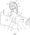
- Fig. 1
- einen Abschnitt eines erfindungsgemäßen Hilfsrahmens, der aus einer Unterschale und einer Oberschale zusammengesetzt ist, in einer Unteransicht, wobei der Abschnitt ein gegenüber der Oberseite der Oberschale nach oben vorstehendes turmförmiges Anbindungsglied aufweist;
- Fig. 2
- den Abschnitt des Hilfsrahmens aus
Fig. 1 in einer perspektivischen Darstellung, wobei die Oberschale entfernt ist; - Fig. 3
- den Abschnitt des Hilfsrahmens aus
Fig. 1 in einer perspektivischen Darstellung, wobei die Unterschale entfernt ist; - Fig. 4
- einen größeren Abschnitt des Hilfsrahmens aus
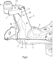
Fig. 1 mit Oberschale und Unterschale in einer perspektivischen Darstellung, die der Perspektive inFig. 3 entspricht; - Fig. 5
- den Abschnitt des Hilfsrahmens aus
Fig. 1 mit Oberschale und Unterschale in einer perspektivischen Darstellung, die der Perspektive inFig. 2 entspricht; und - Fig. 6
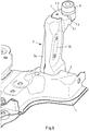
- den Abschnitt des Hilfsrahmens aus
Fig. 5 mit Oberschale und Unterschale in einer anderen perspektivischen Darstellung. - In der Zeichnung ist ein erfindungsgemäßer Hilfsrahmen für eine Kraftfahrzeug in Abschnitten und in verschiedenen Ansichten dargestellt. Der Hilfsrahmen weist Lageraufnahmen für Fahrwerkslenker auf, um als Vormontageeinheit den Einbau eines Vorder- oder Hinterachsmoduls zu ermöglichen. Der Hilfsrahmen ist aus dreidimensional geformten Metallblechen zusammengesetzt, die miteinander verschweißt sind. Die dreidimensional geformten Metallbleche umfassen unter anderem eine Unterschale 1 und eine Oberschale 2. Der Hilfsrahmen weist mindestens zwei voneinander beabstandete, gegenüber der Oberseite der Oberschale 2 nach oben vorstehende turmförmige Anbindungsglieder 3 auf. Die in der Zeichnung dargestellten Abschnitte des Hilfsrahmens zeigen allerdings nur ein von zwei turmförmigen Anbindungsglied 3. Die beiden turmförmigen Anbindungsglieder 3 sind im Wesentlichen spiegelbildlich zueinander ausgeführt.
- Das jeweilige turmförmige Anbindungsglied 3 ist mit der Unterschale 1 und der Oberschale 2 verschweißt. Es erstreckt sich durch eine Ausnehmung 2.1 der Oberschale 2 bis zu der Unterschale 1 und sitzt auf der Unterschale 1 auf, wo es an mindestens einer Aufsitzstelle, vorzugsweise an mindestens zwei Aufsitzstellen 1.1, 1.2 mit der Unterschale 1 verschweißt ist.
- Die Unterschale 1 weist einen relativ zu einem plattenförmigen Bodenabschnitt oder Grundabschnitt der Unterschale nach oben gebogenen Randabschnitt 1.3 auf, der mit einem unteren Kantenabschnitt 3.1 des turmförmigen Anbindungsgliedes 3 verschweißt ist. In den
Figuren 2 und5 ist zu erkennen, dass der untere Kantenabschnitt 3.1 des turmförmigen Anbindungsgliedes 3 mit dem Randabschnitt 1.3 der Unterschale 1 entlang eines im Wesentlichen gerade bzw. horizontal verlaufenden Fügestoßes 4 verschweißt ist. Der Fügestoß 4 ist dabei als Überlappstoß oder vorzugsweise als Stumpfstoß ausgeführt. - Das turmförmige Anbindungsglied 3 weist an seinem der Unterschale 1 zugewandten Ende einen abgekanteten Flansch 3.3 auf, der mit der Innenseite der Unterschale 1 verschweißt ist (vgl.
Fig. 3 ). Die Unterschale 1 ist hierzu im Bereich des Flansches 3.3 mit einer Ausnehmung 1.4 versehen, wobei der Flansch 3.3 zumindest mit einem durch die Ausnehmung 1.4 definierten Kantenabschnitt 1.5 der Unterschale 1 teilweise verschweißt ist. Die Ausnehmung 1.4 ist beispielsweise derart ausgeführt, dass sie mindestens zwei im Wesentlichen geradlinige Kantenabschnitte 1.5 aufweist, die schräg zueinander verlaufen. In dem inFig. 4 gezeigten Ausführungsbeispiel weist die Ausnehmung 1.4 eine im Wesentlichen dreieckige Form mit abgerundeten Ecken auf. Vorzugsweise ist die Schweißverbindung des Flansches 3.3 mit der durch die Ausnehmung 1.4 definierten Kante als umlaufende Kehlschweißnaht ausgeführt. - In
Fig. 3 ist gezeigt, dass sich an dem unteren Kantenabschnitt 3.1 des turmförmigen Anbindungsgliedes 3 einstückig ein zweiter unterer Kantenabschnitt 3.2 anschließt, der relativ zu dem Kantenabschnitt 3.1 abgewinkelt und in einem Hohlraum, der durch die Unterschale 1 und die Oberschale 2 begrenzt ist, angeordnet ist. Der Kantenabschnitt 3.2 ist durch einen abgekanteten Schenkel 3.5 des turmförmigen Anbindungsgliedes 3 definiert. Des Weiteren ist in dem durch die Unterschale 1 und die Oberschale 2 begrenzten Hohlraum ein Verstärkungsblech 6 angeordnet, das mit dem Schenkel 3.5 des turmförmigen Anbindungsgliedes 3, der Oberschale 2 und der Unterschale 1 verschweißt ist. Das Verstärkungsblech 6 weist an seinem der Unterschale 1 zugewandten Ende einen durch Abkanten gebildeten Flansch 6.1 auf, der mit der Innenseite der Unterschale 1 verschweißt ist. Die Unterschale 1 weist hierzu im Bereich des Flansches 6.1 eine Ausnehmung 1.7 auf, wobei der Flansch 6.1 des Verstärkungsblechs 6 mit einem durch die Ausnehmung 1.7 definierten Kantenabschnitt 1.8 der Unterschale 1 verschweißt ist. Im Unterschied zu der dem Flansch 3.3 zugeordneten Ausnehmung 1.4 ist die dem Flansch 6.1 des Verstärkungsblechs 6 zugeordnete Ausnehmung 1.7 schlitzförmig ausgebildet. Die Ausnehmung 1.7 weist parallel zueinander verlaufende Kantenabschnitte auf, die in halbrunden Enden ineinander übergehen. Der an dem turmförmigen Anbindungsglied 3 ausgebildete Flansch 3.3 und der an dem Verstärkungsblech 6 ausgebildete Flansch 6.1 sind aufeinander zu gerichtet, d.h. sie sind vorzugsweise einander zugewandt. - Zur gelenkigen Anbindung eines Fahrwerklenkers (nicht gezeigt) weist das turmförmige Anbindungsglied 3 ein Lagerauge 9 auf, welches zwischen einer Oberseite der Oberschale 2 und der Unterseite der Unterschale 1 angeordnet ist (vgl.
Fig. 3 ). Das Lagerauge 9 ist beispielsweise in Form einer Buchse ausgebildet, die ein Innengewinde aufweist. Die Buchse 9 steht in Richtung des unteren Kantenabschnitts 3.2 des turmförmigen Anbindungsgliedes 3, welcher in dem durch die Unterschale 1 und die Oberschale 2 begrenzten Hohlraum angeordnet ist, vor. Dem Lagerauge 9 ist ein damit fluchtendes Lagerauge 10 zugeordnet, welches in der Oberschale 2 ausgebildet ist. Das Lagerauge 10 ist beispielsweise als Bohrung oder Stanzloch in der Oberschale 2 ausgeführt. Das turmförmige Anbindungsglied 3 ist aus mehreren Metallblechschalen 3a, 3b zusammengesetzt, wobei die Metallblechschale 3b den Flansch 3.3 und das Lagerauge 9 aufweist. - An seinem der Unterschale 1 abgewandten Ende ist das turmförmige Anbindungsglied 3 mit einer separat gefertigten Metallblechschale 7 versehen, die einen Anbindungsabschnitt zur Aufnahme einer Lagerbuchse 8 aufweist. Die Metallblechschale 7 hat zwei Schenkel 7.1, 7.2, wobei einer der Schenkel 7.1 mit einer ersten Metallblechschale 3b und der zweite Schenkel 7.2 mit einer zweiten Metallblechschale 3a des turmförmigen Anbindungsgliedes 3 verschweißt ist. Der Anbindungsabschnitt zur Aufnahme einer Lagerbuchse 8 ist an einem plattenförmigen Mittelsteg 7.3 der Metallblechschale 7 ausgebildet. In dem Mittelsteg 7.3 ist eine halbkreisförmige Einbuchtung 7.4 ausgeschnitten, in welche die Lagerbuchse 8 formschlüssig eingesetzt und mit dem Mittelsteg 7.3 verschweißt ist.
- Die verschiedenen dreidimensional geformten Metallbleche, aus denen der erfindungsgemäße Hilfsrahmen zusammengesetzt ist, sind vorzugsweise aus Stahlblech gefertigt. Die Unterschale 1 und die Oberschale 2 können dabei aus Metallblechen bzw. Stahlblechen unterschiedlicher Blechdicke und/oder Werkstoffgüte, insbesondere unterschiedlicher Zugfestigkeit gefertigt sein. Auch liegt es Rahmen der Erfindung, dass die Metallblechschalen 3a, 3b des turmförmigen Anbindungsgliedes 3, das Verstärkungsblech 6 und die Metallblechschale 7 aus Stahlblechen unterschiedlicher Blechdicke und/oder Werkstoffgüte, insbesondere unterschiedlicher Zugfestigkeit gefertigt sind.
- Die Ausführung des erfindungsgemäßen Hilfsrahmens ist nicht auf das in der Zeichnung dargestellte Ausführungsbeispiel beschränkt. Vielmehr sind zahlreiche Varianten denkbar, die auch bei einer von dem gezeigten Beispiel abweichenden Ausgestaltung von der in den beigefügten Ansprüchen angegebenen Erfindung Gebrauch machen.
Claims (15)
- Hilfsrahmen für ein Kraftfahrzeug, mit einer Unterschale (1), einer Oberschale (2) und mindestens zwei voneinander beabstandeten, gegenüber der Oberseite der Oberschale (2) nach oben vorstehenden, turmförmigen Anbindungsgliedern (3), wobei die Unterschale (1), die Oberschale (2) und die turmförmigen Anbindungsglieder (3) aus Metallblech gefertigt und miteinander verschweißt sind, und wobei sich das jeweilige turmförmige Anbindungsglied (3) durch eine Ausnehmung (2.1) der Oberschale (2) erstreckt, dadurch gekennzeichnet, dass das jeweilige turmförmige Anbindungsglied (3) auf der Unterschale (1) aufsitzt und an einer oder mehreren Aufsitzstellen (1.1, 1.2) mit der Unterschale (1) verschweißt ist.
- Hilfsrahmen nach Anspruch 1, dadurch gekennzeichnet, dass die Unterschale (1) einen nach oben gebogenen Randabschnitt (1.3) aufweist, wobei ein unterer Kantenabschnitt (3.1) des turmförmigen Anbindungsgliedes (3) mit dem nach oben gebogenen Randabschnitt (1.3) der Unterschale (1) verschweißt ist.
- Hilfsrahmen nach Anspruch 2, dadurch gekennzeichnet, dass der untere Kantenabschnitt (3.1) des turmförmigen Anbindungsgliedes (3) mit dem nach oben gebogenen Randabschnitt (1.3) der Unterschale (1) entlang eines im Wesentlichen horizontal und/oder im Wesentlichen gerade verlaufenden Fügestoßes (4) verschweißt ist.
- Hilfsrahmen nach Anspruch 2 oder 3, dadurch gekennzeichnet, dass der untere Kantenabschnitt (3.1) des turmförmigen Anbindungsgliedes (3) mit dem nach oben gebogenen Randabschnitt (1.3) der Unterschale (1) im Stumpfstoß verschweißt ist.
- Hilfsrahmen nach einem der Ansprüche 2 bis 4, dadurch gekennzeichnet, dass sich an den unteren Kantenabschnitt (3.1) des turmförmigen Anbindungsgliedes (3), welcher mit dem nach oben gebogenen Randabschnitt (1.3) der Unterschale (1) verschweißt ist, ein zweiter unterer Kantenabschnitt (3.2) des turmförmigen Anbindungsgliedes (3) anschließt, der relativ zu dem mit dem nach oben gebogenen Randabschnitt (1.3) der Unterschale (1) verschweißten Kantenabschnitt (3.1) abgewinkelt und in dem durch die Unterschale (1) und die Oberschale (2) begrenzten Hohlraum angeordnet ist.
- Hilfsrahmen nach einem der Ansprüche 1 bis 5, dadurch gekennzeichnet, dass das turmförmige Anbindungsglied (3) an seinem der Unterschale (1) zugewandten Ende einen abgekanteten Flansch (3.3) aufweist, der mit der Innenseite der Unterschale (1) verschweißt ist.
- Hilfsrahmen nach Anspruch 6, dadurch gekennzeichnet, dass die Unterschale (1) im Bereich des Flansches (3.3) eine Ausnehmung (1.4) aufweist, wobei der Flansch (3.3) zumindest mit einem durch die Ausnehmung (1.4) definierten Kantenabschnitt (1.5) der Unterschale (1) verschweißt ist.
- Hilfsrahmen nach einem der Ansprüche 1 bis 7, dadurch gekennzeichnet, dass das turmförmige Anbindungsglied (3) ein Lagerauge (9) zur gelenkigen Anbindung eines Fahrwerklenkers aufweist, wobei das Lagerauge (9) zwischen einer Oberseite der Oberschale (2) und der Unterseite der Unterschale (1) angeordnet ist.
- Hilfsrahmen nach einem der Ansprüche 6 bis 8, dadurch gekennzeichnet, dass das turmförmige Anbindungsglied (3) aus mehreren Metallblechschalen (3a, 3b) zusammengesetzt ist, wobei eine seiner Metallblechschalen (3b) den Flansch (3.3) und/oder das Lagerauge (9) aufweist.
- Hilfsrahmen nach einem der Ansprüche 1 bis 9, dadurch gekennzeichnet, dass in dem durch die Unterschale (1) und die Oberschale (2) begrenzten Hohlraum ein Verstärkungsblech (6) angeordnet ist, das mit dem turmförmigen Anbindungsglied (3), der Oberschale (2) sowie der Unterschale (1) verschweißt ist.
- Hilfsrahmen nach Anspruch 10, dadurch gekennzeichnet, dass das Verstärkungsblech (6) an seinem der Unterschale (1) zugewandten Ende einen abgekanteten Flansch (6.1) aufweist, der mit der Innenseite der Unterschale (1) verschweißt ist.
- Hilfsrahmen nach Anspruch 11, dadurch gekennzeichnet, dass die Unterschale (1) im Bereich des Flansches (6.1) eine Ausnehmung (1.7) aufweist, wobei der Flansch (6.1) des Verstärkungsblechs (6) mit einem durch die Ausnehmung (1.7) definierten Kantenabschnitt (1.8) der Unterschale (1) verschweißt ist.
- Hilfsrahmen nach Anspruch 5 und einem der Ansprüche 10 bis 12, dadurch gekennzeichnet, dass der zweite untere Kantenabschnitt (3.2) durch einen Schenkel (3.5) des turmförmigen Anbindungsgliedes (3) definiert ist, wobei der Schenkel (3.5) mit dem Verstärkungsblech (6) verschweißt ist.
- Hilfsrahmen nach einem der Ansprüche 1 bis 13, dadurch gekennzeichnet, dass das turmförmige Anbindungsglied (3) an seinem der Unterschale (1) abgewandten Ende mit einer separat gefertigten Metallblechschale (7) versehen ist, wobei die Metallblechschale (7) einen Anbindungsabschnitt zur Aufnahme einer Lagerbuchse (8) aufweist.
- Hilfsrahmen nach Anspruch 14, dadurch gekennzeichnet, dass die Metallblechschale (7) mindestens zwei Schenkel (7.1, 7.2) aufweist, wobei einer der Schenkel (7.1) mit einer ersten Metallblechschale (3b) des turmförmigen Anbindungsgliedes (3) verschweißt ist, während der zweite Schenkel (7.2) mit einer zweiten Metallblechschale (3a) des turmförmigen Anbindungsgliedes (3) verschweißt ist.
Priority Applications (2)
| Application Number | Priority Date | Filing Date | Title |
|---|---|---|---|
| EP18188643.3A EP3611079B8 (de) | 2018-08-13 | 2018-08-13 | Hilfsrahmen für kraftfahrzeuge |
| ES18188643T ES2902781T3 (es) | 2018-08-13 | 2018-08-13 | Chasis auxiliar para automóviles |
Applications Claiming Priority (1)
| Application Number | Priority Date | Filing Date | Title |
|---|---|---|---|
| EP18188643.3A EP3611079B8 (de) | 2018-08-13 | 2018-08-13 | Hilfsrahmen für kraftfahrzeuge |
Publications (3)
| Publication Number | Publication Date |
|---|---|
| EP3611079A1 true EP3611079A1 (de) | 2020-02-19 |
| EP3611079B1 EP3611079B1 (de) | 2021-12-08 |
| EP3611079B8 EP3611079B8 (de) | 2023-05-03 |
Family
ID=63244449
Family Applications (1)
| Application Number | Title | Priority Date | Filing Date |
|---|---|---|---|
| EP18188643.3A Active EP3611079B8 (de) | 2018-08-13 | 2018-08-13 | Hilfsrahmen für kraftfahrzeuge |
Country Status (2)
| Country | Link |
|---|---|
| EP (1) | EP3611079B8 (de) |
| ES (1) | ES2902781T3 (de) |
Cited By (1)
| Publication number | Priority date | Publication date | Assignee | Title |
|---|---|---|---|---|
| CN120080914A (zh) * | 2025-04-10 | 2025-06-03 | 浙江吉利控股集团有限公司 | 副车架总成和具有其的车辆 |
Citations (4)
| Publication number | Priority date | Publication date | Assignee | Title |
|---|---|---|---|---|
| DE102014013908A1 (de) | 2013-09-20 | 2015-03-26 | Mazda Motor Corporation | Fahrzeugkarosserie-Frontstruktur und Verfahren zum Erhöhen der Steifigkeit eines Turmabschnittes |
| EP2990308A1 (de) * | 2014-08-25 | 2016-03-02 | Benteler Automobiltechnik GmbH | Achsträger für ein kraftfahrzeug sowie verfahren zur herstellung eines achsträgers |
| EP3020618A1 (de) * | 2013-07-11 | 2016-05-18 | F.Tech Incorporation | Aufbau für fahrzeug |
| WO2018065510A1 (de) * | 2016-10-06 | 2018-04-12 | Kirchhoff Automotive Deutschland Gmbh | Trägerkonstruktion für ein fahrzeug |
-
2018
- 2018-08-13 ES ES18188643T patent/ES2902781T3/es active Active
- 2018-08-13 EP EP18188643.3A patent/EP3611079B8/de active Active
Patent Citations (4)
| Publication number | Priority date | Publication date | Assignee | Title |
|---|---|---|---|---|
| EP3020618A1 (de) * | 2013-07-11 | 2016-05-18 | F.Tech Incorporation | Aufbau für fahrzeug |
| DE102014013908A1 (de) | 2013-09-20 | 2015-03-26 | Mazda Motor Corporation | Fahrzeugkarosserie-Frontstruktur und Verfahren zum Erhöhen der Steifigkeit eines Turmabschnittes |
| EP2990308A1 (de) * | 2014-08-25 | 2016-03-02 | Benteler Automobiltechnik GmbH | Achsträger für ein kraftfahrzeug sowie verfahren zur herstellung eines achsträgers |
| WO2018065510A1 (de) * | 2016-10-06 | 2018-04-12 | Kirchhoff Automotive Deutschland Gmbh | Trägerkonstruktion für ein fahrzeug |
Cited By (1)
| Publication number | Priority date | Publication date | Assignee | Title |
|---|---|---|---|---|
| CN120080914A (zh) * | 2025-04-10 | 2025-06-03 | 浙江吉利控股集团有限公司 | 副车架总成和具有其的车辆 |
Also Published As
| Publication number | Publication date |
|---|---|
| EP3611079B1 (de) | 2021-12-08 |
| EP3611079B8 (de) | 2023-05-03 |
| ES2902781T3 (es) | 2022-03-29 |
Similar Documents
| Publication | Publication Date | Title |
|---|---|---|
| DE102013108695B4 (de) | Hilfsrahmen für eine Kraftfahrzeugachse | |
| DE102006013548B4 (de) | Als Fahrschemel ausgebildeter Hilfsrahmen für Kraftfahrzeuge sowie Fahrzeugkarosserie | |
| DE102012005561B4 (de) | Hilfsrahmen für ein Kraftfahrzeug | |
| DE102007030929B4 (de) | Achsträger für Kraftfahrzeuge | |
| DE60312863T2 (de) | Fahrgestell | |
| DE102016000670B3 (de) | Hilfsrahmen für ein zweispuriges Kraftfahrzeug | |
| DE10232841A1 (de) | Bodenträgeranordnung an Kraftfahrzeugen | |
| EP2927029A1 (de) | Verfahren zum Herstellen eines Fahrwerklenkers | |
| DE10047880B4 (de) | Fahrschemelkonstruktion für ein Kraftfahrzeug | |
| DE19722646A1 (de) | Verbindungs- und Traganordnung für Fahrzeugrahmenanordnung | |
| DE102009042060A1 (de) | Strukturbauteil für Hinterrahmenstruktur eines Kraftfahrzeugs | |
| DE102009050058A1 (de) | Verbundlenkerachse und Verfahren zur Herstellung von Verbundlenkerachsen für Kraftfahrzeuge | |
| EP2141035A1 (de) | Mehrpunktlenkeranordnung für einen Fahrzeugrahmen eines Nutzfahrzeuges sowie Trägerkonsole und Querträger für eine Mehrpunktlenkeranordnung | |
| EP3611079B1 (de) | Hilfsrahmen für kraftfahrzeuge | |
| EP0940319A2 (de) | Fahrgestell eines schweren Nutzfahrzeuges | |
| DE10254693A1 (de) | Vorderwagenstruktur | |
| DE102006017225A1 (de) | Hilfsrahmen für Kraftfahrzeuge | |
| EP3870463B1 (de) | Federlenker in blechkonstruktion | |
| DE102021109912A1 (de) | Halbstarrachse für ein Fahrzeug | |
| DE19846399A1 (de) | Verbundlenker-Hinterachse | |
| DE102017202215A1 (de) | Hilfsrahmen für ein Kraftfahrzeug | |
| DE19809196A1 (de) | Fahrgestell eines schweren Nutzfahrzeuges | |
| EP3450041B1 (de) | Verfahren zur herstellung eines rohrförmigen hohlkörpers aus einer zugeschnittenen metallischen platine und fahrwerks- oder karosseriebauteil mit einem nach dem verfahren hergestellten hohlkörper | |
| EP0940322A1 (de) | Fahrgestell eines schweren Nutzfahrzeuges | |
| DE102016013301A1 (de) | Fahrzeugsäule für ein Kraftfahrzeug und Verfahren zum Herstellen einer Fahrzeugsäule für ein Kraftfahrzeug |
Legal Events
| Date | Code | Title | Description |
|---|---|---|---|
| PUAI | Public reference made under article 153(3) epc to a published international application that has entered the european phase |
Free format text: ORIGINAL CODE: 0009012 |
|
| STAA | Information on the status of an ep patent application or granted ep patent |
Free format text: STATUS: THE APPLICATION HAS BEEN PUBLISHED |
|
| AK | Designated contracting states |
Kind code of ref document: A1 Designated state(s): AL AT BE BG CH CY CZ DE DK EE ES FI FR GB GR HR HU IE IS IT LI LT LU LV MC MK MT NL NO PL PT RO RS SE SI SK SM TR |
|
| AX | Request for extension of the european patent |
Extension state: BA ME |
|
| STAA | Information on the status of an ep patent application or granted ep patent |
Free format text: STATUS: REQUEST FOR EXAMINATION WAS MADE |
|
| 17P | Request for examination filed |
Effective date: 20200416 |
|
| RBV | Designated contracting states (corrected) |
Designated state(s): AL AT BE BG CH CY CZ DE DK EE ES FI FR GB GR HR HU IE IS IT LI LT LU LV MC MK MT NL NO PL PT RO RS SE SI SK SM TR |
|
| GRAP | Despatch of communication of intention to grant a patent |
Free format text: ORIGINAL CODE: EPIDOSNIGR1 |
|
| STAA | Information on the status of an ep patent application or granted ep patent |
Free format text: STATUS: GRANT OF PATENT IS INTENDED |
|
| INTG | Intention to grant announced |
Effective date: 20210909 |
|
| GRAS | Grant fee paid |
Free format text: ORIGINAL CODE: EPIDOSNIGR3 |
|
| GRAA | (expected) grant |
Free format text: ORIGINAL CODE: 0009210 |
|
| STAA | Information on the status of an ep patent application or granted ep patent |
Free format text: STATUS: THE PATENT HAS BEEN GRANTED |
|
| RAP3 | Party data changed (applicant data changed or rights of an application transferred) |
Owner name: GESTAMP METALBAGES, S.A. Owner name: GESTAMP MANUFACTURING AUTOCHASSIS, S.L. Owner name: AUTOTECH ENGINEERING S.L. Owner name: AUTOTECH ENGINEERING DEUTSCHLAND GMBH |
|
| AK | Designated contracting states |
Kind code of ref document: B1 Designated state(s): AL AT BE BG CH CY CZ DE DK EE ES FI FR GB GR HR HU IE IS IT LI LT LU LV MC MK MT NL NO PL PT RO RS SE SI SK SM TR |
|
| REG | Reference to a national code |
Ref country code: GB Ref legal event code: FG4D Free format text: NOT ENGLISH |
|
| REG | Reference to a national code |
Ref country code: AT Ref legal event code: REF Ref document number: 1453567 Country of ref document: AT Kind code of ref document: T Effective date: 20211215 Ref country code: CH Ref legal event code: EP |
|
| REG | Reference to a national code |
Ref country code: DE Ref legal event code: R096 Ref document number: 502018008102 Country of ref document: DE |
|
| REG | Reference to a national code |
Ref country code: IE Ref legal event code: FG4D Free format text: LANGUAGE OF EP DOCUMENT: GERMAN |
|
| REG | Reference to a national code |
Ref country code: ES Ref legal event code: FG2A Ref document number: 2902781 Country of ref document: ES Kind code of ref document: T3 Effective date: 20220329 |
|
| REG | Reference to a national code |
Ref country code: LT Ref legal event code: MG9D |
|
| REG | Reference to a national code |
Ref country code: NL Ref legal event code: MP Effective date: 20211208 |
|
| PG25 | Lapsed in a contracting state [announced via postgrant information from national office to epo] |
Ref country code: RS Free format text: LAPSE BECAUSE OF FAILURE TO SUBMIT A TRANSLATION OF THE DESCRIPTION OR TO PAY THE FEE WITHIN THE PRESCRIBED TIME-LIMIT Effective date: 20211208 Ref country code: LT Free format text: LAPSE BECAUSE OF FAILURE TO SUBMIT A TRANSLATION OF THE DESCRIPTION OR TO PAY THE FEE WITHIN THE PRESCRIBED TIME-LIMIT Effective date: 20211208 Ref country code: FI Free format text: LAPSE BECAUSE OF FAILURE TO SUBMIT A TRANSLATION OF THE DESCRIPTION OR TO PAY THE FEE WITHIN THE PRESCRIBED TIME-LIMIT Effective date: 20211208 Ref country code: BG Free format text: LAPSE BECAUSE OF FAILURE TO SUBMIT A TRANSLATION OF THE DESCRIPTION OR TO PAY THE FEE WITHIN THE PRESCRIBED TIME-LIMIT Effective date: 20220308 |
|
| PG25 | Lapsed in a contracting state [announced via postgrant information from national office to epo] |
Ref country code: SE Free format text: LAPSE BECAUSE OF FAILURE TO SUBMIT A TRANSLATION OF THE DESCRIPTION OR TO PAY THE FEE WITHIN THE PRESCRIBED TIME-LIMIT Effective date: 20211208 Ref country code: NO Free format text: LAPSE BECAUSE OF FAILURE TO SUBMIT A TRANSLATION OF THE DESCRIPTION OR TO PAY THE FEE WITHIN THE PRESCRIBED TIME-LIMIT Effective date: 20220308 Ref country code: LV Free format text: LAPSE BECAUSE OF FAILURE TO SUBMIT A TRANSLATION OF THE DESCRIPTION OR TO PAY THE FEE WITHIN THE PRESCRIBED TIME-LIMIT Effective date: 20211208 Ref country code: HR Free format text: LAPSE BECAUSE OF FAILURE TO SUBMIT A TRANSLATION OF THE DESCRIPTION OR TO PAY THE FEE WITHIN THE PRESCRIBED TIME-LIMIT Effective date: 20211208 |
|
| PG25 | Lapsed in a contracting state [announced via postgrant information from national office to epo] |
Ref country code: NL Free format text: LAPSE BECAUSE OF FAILURE TO SUBMIT A TRANSLATION OF THE DESCRIPTION OR TO PAY THE FEE WITHIN THE PRESCRIBED TIME-LIMIT Effective date: 20211208 |
|
| PG25 | Lapsed in a contracting state [announced via postgrant information from national office to epo] |
Ref country code: SM Free format text: LAPSE BECAUSE OF FAILURE TO SUBMIT A TRANSLATION OF THE DESCRIPTION OR TO PAY THE FEE WITHIN THE PRESCRIBED TIME-LIMIT Effective date: 20211208 Ref country code: SK Free format text: LAPSE BECAUSE OF FAILURE TO SUBMIT A TRANSLATION OF THE DESCRIPTION OR TO PAY THE FEE WITHIN THE PRESCRIBED TIME-LIMIT Effective date: 20211208 Ref country code: RO Free format text: LAPSE BECAUSE OF FAILURE TO SUBMIT A TRANSLATION OF THE DESCRIPTION OR TO PAY THE FEE WITHIN THE PRESCRIBED TIME-LIMIT Effective date: 20211208 Ref country code: PT Free format text: LAPSE BECAUSE OF FAILURE TO SUBMIT A TRANSLATION OF THE DESCRIPTION OR TO PAY THE FEE WITHIN THE PRESCRIBED TIME-LIMIT Effective date: 20220408 Ref country code: EE Free format text: LAPSE BECAUSE OF FAILURE TO SUBMIT A TRANSLATION OF THE DESCRIPTION OR TO PAY THE FEE WITHIN THE PRESCRIBED TIME-LIMIT Effective date: 20211208 Ref country code: CZ Free format text: LAPSE BECAUSE OF FAILURE TO SUBMIT A TRANSLATION OF THE DESCRIPTION OR TO PAY THE FEE WITHIN THE PRESCRIBED TIME-LIMIT Effective date: 20211208 |
|
| PG25 | Lapsed in a contracting state [announced via postgrant information from national office to epo] |
Ref country code: PL Free format text: LAPSE BECAUSE OF FAILURE TO SUBMIT A TRANSLATION OF THE DESCRIPTION OR TO PAY THE FEE WITHIN THE PRESCRIBED TIME-LIMIT Effective date: 20211208 |
|
| REG | Reference to a national code |
Ref country code: DE Ref legal event code: R097 Ref document number: 502018008102 Country of ref document: DE |
|
| PG25 | Lapsed in a contracting state [announced via postgrant information from national office to epo] |
Ref country code: IS Free format text: LAPSE BECAUSE OF FAILURE TO SUBMIT A TRANSLATION OF THE DESCRIPTION OR TO PAY THE FEE WITHIN THE PRESCRIBED TIME-LIMIT Effective date: 20220408 |
|
| PLBE | No opposition filed within time limit |
Free format text: ORIGINAL CODE: 0009261 |
|
| STAA | Information on the status of an ep patent application or granted ep patent |
Free format text: STATUS: NO OPPOSITION FILED WITHIN TIME LIMIT |
|
| PG25 | Lapsed in a contracting state [announced via postgrant information from national office to epo] |
Ref country code: DK Free format text: LAPSE BECAUSE OF FAILURE TO SUBMIT A TRANSLATION OF THE DESCRIPTION OR TO PAY THE FEE WITHIN THE PRESCRIBED TIME-LIMIT Effective date: 20211208 Ref country code: AL Free format text: LAPSE BECAUSE OF FAILURE TO SUBMIT A TRANSLATION OF THE DESCRIPTION OR TO PAY THE FEE WITHIN THE PRESCRIBED TIME-LIMIT Effective date: 20211208 |
|
| 26N | No opposition filed |
Effective date: 20220909 |
|
| PG25 | Lapsed in a contracting state [announced via postgrant information from national office to epo] |
Ref country code: SI Free format text: LAPSE BECAUSE OF FAILURE TO SUBMIT A TRANSLATION OF THE DESCRIPTION OR TO PAY THE FEE WITHIN THE PRESCRIBED TIME-LIMIT Effective date: 20211208 |
|
| PG25 | Lapsed in a contracting state [announced via postgrant information from national office to epo] |
Ref country code: MC Free format text: LAPSE BECAUSE OF FAILURE TO SUBMIT A TRANSLATION OF THE DESCRIPTION OR TO PAY THE FEE WITHIN THE PRESCRIBED TIME-LIMIT Effective date: 20211208 |
|
| PLAA | Information modified related to event that no opposition was filed |
Free format text: ORIGINAL CODE: 0009299DELT |
|
| PLBE | No opposition filed within time limit |
Free format text: ORIGINAL CODE: 0009261 |
|
| REG | Reference to a national code |
Ref country code: CH Ref legal event code: PL |
|
| REG | Reference to a national code |
Ref country code: CH Ref legal event code: PK Free format text: BERICHTIGUNG B8 |
|
| GBPC | Gb: european patent ceased through non-payment of renewal fee |
Effective date: 20220813 |
|
| PG25 | Lapsed in a contracting state [announced via postgrant information from national office to epo] |
Ref country code: LU Free format text: LAPSE BECAUSE OF NON-PAYMENT OF DUE FEES Effective date: 20220813 Ref country code: LI Free format text: LAPSE BECAUSE OF NON-PAYMENT OF DUE FEES Effective date: 20220831 Ref country code: CH Free format text: LAPSE BECAUSE OF NON-PAYMENT OF DUE FEES Effective date: 20220831 |
|
| REG | Reference to a national code |
Ref country code: BE Ref legal event code: MM Effective date: 20220831 |
|
| R26N | No opposition filed (corrected) |
Effective date: 20220909 |
|
| RAP2 | Party data changed (patent owner data changed or rights of a patent transferred) |
Owner name: GESTAMP METALBAGES, S.A. Owner name: GESTAMP MANUFACTURING AUTOCHASIS, S.L. Owner name: AUTOTECH ENGINEERING S.L. Owner name: AUTOTECH ENGINEERING DEUTSCHLAND GMBH |
|
| PG25 | Lapsed in a contracting state [announced via postgrant information from national office to epo] |
Ref country code: IT Free format text: LAPSE BECAUSE OF FAILURE TO SUBMIT A TRANSLATION OF THE DESCRIPTION OR TO PAY THE FEE WITHIN THE PRESCRIBED TIME-LIMIT Effective date: 20211208 |
|
| PG25 | Lapsed in a contracting state [announced via postgrant information from national office to epo] |
Ref country code: IE Free format text: LAPSE BECAUSE OF NON-PAYMENT OF DUE FEES Effective date: 20220813 |
|
| PG25 | Lapsed in a contracting state [announced via postgrant information from national office to epo] |
Ref country code: BE Free format text: LAPSE BECAUSE OF NON-PAYMENT OF DUE FEES Effective date: 20220831 |
|
| PG25 | Lapsed in a contracting state [announced via postgrant information from national office to epo] |
Ref country code: GB Free format text: LAPSE BECAUSE OF NON-PAYMENT OF DUE FEES Effective date: 20220813 |
|
| PG25 | Lapsed in a contracting state [announced via postgrant information from national office to epo] |
Ref country code: HU Free format text: LAPSE BECAUSE OF FAILURE TO SUBMIT A TRANSLATION OF THE DESCRIPTION OR TO PAY THE FEE WITHIN THE PRESCRIBED TIME-LIMIT; INVALID AB INITIO Effective date: 20180813 |
|
| PG25 | Lapsed in a contracting state [announced via postgrant information from national office to epo] |
Ref country code: CY Free format text: LAPSE BECAUSE OF FAILURE TO SUBMIT A TRANSLATION OF THE DESCRIPTION OR TO PAY THE FEE WITHIN THE PRESCRIBED TIME-LIMIT Effective date: 20211208 |
|
| PG25 | Lapsed in a contracting state [announced via postgrant information from national office to epo] |
Ref country code: MK Free format text: LAPSE BECAUSE OF FAILURE TO SUBMIT A TRANSLATION OF THE DESCRIPTION OR TO PAY THE FEE WITHIN THE PRESCRIBED TIME-LIMIT Effective date: 20211208 |
|
| PG25 | Lapsed in a contracting state [announced via postgrant information from national office to epo] |
Ref country code: TR Free format text: LAPSE BECAUSE OF FAILURE TO SUBMIT A TRANSLATION OF THE DESCRIPTION OR TO PAY THE FEE WITHIN THE PRESCRIBED TIME-LIMIT Effective date: 20211208 |
|
| PG25 | Lapsed in a contracting state [announced via postgrant information from national office to epo] |
Ref country code: MT Free format text: LAPSE BECAUSE OF FAILURE TO SUBMIT A TRANSLATION OF THE DESCRIPTION OR TO PAY THE FEE WITHIN THE PRESCRIBED TIME-LIMIT Effective date: 20211208 |
|
| REG | Reference to a national code |
Ref country code: AT Ref legal event code: MM01 Ref document number: 1453567 Country of ref document: AT Kind code of ref document: T Effective date: 20230813 |
|
| PGFP | Annual fee paid to national office [announced via postgrant information from national office to epo] |
Ref country code: FR Payment date: 20240826 Year of fee payment: 7 |
|
| PG25 | Lapsed in a contracting state [announced via postgrant information from national office to epo] |
Ref country code: AT Free format text: LAPSE BECAUSE OF NON-PAYMENT OF DUE FEES Effective date: 20230813 |
|
| PG25 | Lapsed in a contracting state [announced via postgrant information from national office to epo] |
Ref country code: AT Free format text: LAPSE BECAUSE OF NON-PAYMENT OF DUE FEES Effective date: 20230813 |
|
| PG25 | Lapsed in a contracting state [announced via postgrant information from national office to epo] |
Ref country code: GR Free format text: LAPSE BECAUSE OF NON-PAYMENT OF DUE FEES Effective date: 20211208 |
|
| PG25 | Lapsed in a contracting state [announced via postgrant information from national office to epo] |
Ref country code: GR Free format text: LAPSE BECAUSE OF NON-PAYMENT OF DUE FEES Effective date: 20211208 |
|
| PGFP | Annual fee paid to national office [announced via postgrant information from national office to epo] |
Ref country code: ES Payment date: 20250901 Year of fee payment: 8 |
|
| PGFP | Annual fee paid to national office [announced via postgrant information from national office to epo] |
Ref country code: DE Payment date: 20250827 Year of fee payment: 8 |
|
| PGFP | Annual fee paid to national office [announced via postgrant information from national office to epo] |
Ref country code: AT Payment date: 20260410 Year of fee payment: 5 |